70/140H-8 Series (2310KB) - TAIYO
70/140H-8 Series (2310KB) - TAIYO
70/140H-8 Series (2310KB) - TAIYO

You also want an ePaper? Increase the reach of your titles
YUMPU automatically turns print PDFs into web optimized ePapers that Google loves.
17<br />
Selection materials<br />
~~~~~~~~~~~~~~~~~~~~~~~~~~~~~~~~~~~~~~~~~~~~~~~~~~~~~~~~~<br />
Selection<br />
materials<br />
1) Be sure to calculate the cylinder buckling.<br />
2) In the case of using a hydraulic cylinder, the stress<br />
and buckling must be considered depending on the<br />
cylinder stroke.<br />
The strength in the case that the piston rod is<br />
regarded as a long column, the buckling strength,<br />
cannot be enhanced by adopting highly tension-proof<br />
steel or heat treatment. The only way to improve the<br />
buckling strength of a cylinder is to widen the piston<br />
rod dia., and therefore, the selection of the piston<br />
rod is the very important point.<br />
The buckling chart shown in the next page, based<br />
on the Euler’s equation that is applicable to an<br />
upright long column, indicates the maximum safe L<br />
values against the piston rod dia. when the cylinder<br />
is used with the compressive load that is most<br />
frequently applied.<br />
3) When buckling occurs to a cylinder, the cylinder rod<br />
may be bent, causing malfunctions or serious<br />
accidents.<br />
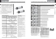
Magnetic proximity type (with contact)<br />
Calculation of cylinder buckling Calculation method of cylinder buckling (use of buckling chart)<br />
1. Find the L value (distance between the cylinder<br />
mounting position and load mounting position) with<br />
a cylinder fully extended.<br />
2. Select any buckling chart depending on the<br />
mounting style, and find the maximum working load.<br />
< Exercise ><br />
Find the maximum working load for the <strong>140H</strong>-8, φ50,<br />
rod B (rod dia. φ28), in case that the stroke is<br />
1000 mm, CA type with the rod end eye.<br />
< Answer ><br />
1. Find the L value with the cylinder fully extended.<br />
From the dimensional drawings in this catalogue, the<br />
L value can be calculated by the formula below.<br />
L = 230 + <strong>70</strong> + 1000 + 1000 = 2300 mm<br />
2. From the buckling chart of the both ends pin joints,<br />
the load can be found as below.<br />
W = 3 kN (=.<br />
. 306 kgf)<br />
~~~~~~~~~~~~~~~~~~~~~~~~~~~~~~~~~~~~~~~~~~~~~~~~~~~~~~~~~~~~~~~~~~~~~~~~~~~~~~~~~~~~~~~<br />
Notes on piston rod buckling<br />
Prior to the calculation of the piston rod buckling, consider the cylinder stopping method. The stopping<br />
methods of a cylinder include the cylinder stopping method, in which a cylinder is stopped at the stroke end,<br />
and the external stopping method, in which a cylinder is stopped with the external stopper. The definition of<br />
load differs depending on the selection of the stopping method as shown below.<br />
● Definition of a load when the cylinder stopping<br />
method is selected<br />
In the case<br />
of 1<br />
M<br />
M<br />
In the case of 2<br />
The state of stopping at the cylinder stroke<br />
end as shown in the figure.<br />
For the load required for the buckling<br />
calculation, apply the formula below.<br />
In the case of 1 : load = M • g<br />
In the case of 2 : load = µ M • g<br />
µ : frictional coefficient<br />
g : gravity acceleration<br />
9.8 m/s2 M : load weight (kg)<br />
● Definition of load when the external stopping<br />
method is selected<br />
The state of halfway stopping with<br />
the external stopper as shown in<br />
the figure.<br />
The load required for the buckling<br />
calculation in this case is not the<br />
M, but the cylinder theoretical<br />
output (relief set pressure MPa ×<br />
piston area mm 2 ).<br />
~~~~~~~~~~~~~~~~~~~~~~~~~~~~~~~~~~~~~~~~~~~~~~~~~~~~~~~~~~~~~~~~~~~~~~~~~~~~~~~~~~~~~~~<br />
M<br />
L<br />
Load<br />
3kN<br />
M<br />
L<br />
Rod dia. (φ28)<br />
2300<br />
φ50 (Rod B type)<br />
mm<br />
~~~~~~~~~~~~~~~~~~~~~~~~~~~~~~~~~~~~~~~~~~~~~~~~~~~~~~~~~