70/140H-8 Series (2310KB) - TAIYO
70/140H-8 Series (2310KB) - TAIYO
70/140H-8 Series (2310KB) - TAIYO

You also want an ePaper? Increase the reach of your titles
YUMPU automatically turns print PDFs into web optimized ePapers that Google loves.
51<br />
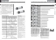
General purpose hydraulic cylinder<br />
<strong>70</strong>/<strong>140H</strong>-8<br />
MM<br />
LA<br />
<strong>70</strong>H-8 0 1 LA Bore B B Stroke – A B<br />
<strong>140H</strong>-8 1 LA Bore B B Stroke – A B<br />
● Bore φ32 - φ160<br />
KK<br />
A W FP<br />
ZB + stroke<br />
PJ + stroke<br />
E<br />
SL 2-EE<br />
A<br />
SY SU<br />
Cushion<br />
valve SU SY<br />
XS<br />
SS + stroke<br />
XB + stroke<br />
● For the dimensions other than in the diagram above,<br />
refer to the specification of the SD type (standard<br />
type).<br />
● For the mounting of switches, refer to the dimensional<br />
drawings of “Switch set”. All the contents other than<br />
“Switch mounting dimensions” are identical.<br />
With boots<br />
φWW<br />
Rod B • C<br />
Nylon tarpaulin<br />
Chloroprene<br />
Conex<br />
⎞ ⎟⎟⎟⎟⎠<br />
⎞ ⎟⎟⎟⎟⎟⎠<br />
W<br />
7/14 MPa double acting hydraulic cylinder<br />
Double acting single rod/double rod Unit: mm<br />
D<br />
C<br />
TS<br />
US<br />
φ32 1/ 3 Stroke + X<br />
φ40 • φ50 1/ 3.5 Stroke + X<br />
φ63 - φ100 1/4 Stroke + X<br />
φ125 - φ200 1/5 Stroke + X<br />
φ224 • φ250 1/6 Stroke + X<br />
φ32 1/2 Stroke + X<br />
φ40 • φ50 1/2.5 Stroke + X<br />
φ63 - φ100 1/3 Stroke + X<br />
φ125 • φ140 1/3.5 Stroke + X<br />
φ150 - φ200 1/4 Stroke + X<br />
φ224 • φ250 1/4.5 Stroke + X<br />
⎞<br />
⎟<br />
⎠<br />
⎞<br />
⎟<br />
⎠<br />
MM<br />
φ32 - φ100 :Max. 7<br />
φ125 - φ150 :Max. 11<br />
φ160 - φ250 :Max. 13<br />
B<br />
S<br />
LH<br />
ST<br />
KK<br />
VD<br />
B OF<br />
4-SB<br />
A<br />
<strong>70</strong>-<strong>140H</strong>-8/TH8 Bore A.C<br />
For the rod dia. of φ100 or<br />
more, a drill hole will be<br />
applied.<br />
2-DF<br />
EH<br />
W<br />
XS<br />
FP<br />
MM<br />
Material<br />
Resistible<br />
temperature<br />
KK<br />
A W FP<br />
XS<br />
2-EE<br />
ZB + stroke<br />
PJ + stroke<br />
Cushion<br />
SY SX valve SW SY<br />
SS + stroke<br />
XB + stroke<br />
PJ + stroke FP<br />
W +<br />
stroke A<br />
SV + stroke<br />
Standard<br />
Nylon tarpaulin<br />
80°C<br />
CAD/DATA is<br />
available.<br />
Rod<br />
dia.<br />
φ100<br />
φ112<br />
φ125<br />
φ140<br />
OF<br />
φ99.5<br />
φ111.5<br />
φ124.5<br />
φ139.5<br />
● Bore φ180 - φ250<br />
Double rod type (φ32 - φ160/rod B, C)<br />
For both ends loaded type<br />
XS + stroke<br />
● The switch set (φ32 - φ140) is also within the fabrication range.<br />
Chloroprene<br />
130°C<br />
KK<br />
<strong>70</strong>-<strong>140H</strong>-8/TH8 Bore K<br />
Semi-standard<br />
DF<br />
φ12<br />
φ15<br />
φ15<br />
φ15<br />
MM<br />
Conex<br />
200°C<br />
Notes) ● Remember that the resistible temperatures shown in the table above are for the<br />
boots, not for the cylinder.<br />
● Conex is the registered trademark of Teijin Ltd.<br />
● If decimals are included into the calculation results, raise them to the next whole<br />
number.<br />
● The boots have been mounted at our factory prior to delivery.<br />
Rod A<br />
Nylon tarpaulin<br />
Chloroprene<br />
Conex<br />
35<br />
φ40 1/ 3.5 Stroke + X<br />
φ50 - φ80 1/4 Stroke + X<br />
φ100 - φ160 1/5 Stroke + X<br />
φ40 1/2.5 Stroke + X<br />
φ50 - φ80 1/3 Stroke + X<br />
φ100 1/3.5 Stroke + X<br />
φ125 - φ160 1/4 Stroke + X<br />
⎞ ⎟⎟⎠<br />
⎞ ⎟⎟⎟⎠<br />
⎞<br />
⎟<br />
⎠<br />
⎞<br />
⎟<br />
⎠