70/140H-8 Series (2310KB) - TAIYO
70/140H-8 Series (2310KB) - TAIYO
70/140H-8 Series (2310KB) - TAIYO

You also want an ePaper? Increase the reach of your titles
YUMPU automatically turns print PDFs into web optimized ePapers that Google loves.
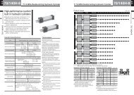
Standard built-in high-performance cushion <strong>70</strong>/<strong>140H</strong>-8 series<br />
Enhanced cushioning effect to keep up with high-speed machines.<br />
Identical mounting dimensions to those of <strong>70</strong>/<strong>140H</strong>-7 series that are<br />
field-proven for long years (conform to JIS standards)<br />
Enhanced cushioning function has reduced<br />
shocks occurring when actuator stops.<br />
Acceleration during deceleration<br />
(G-value)<br />
G-value after inrush into cushion (inrush speed 400 mm/s)<br />
1.5<br />
1.0<br />
0.5<br />
0<br />
0.5<br />
Inrush into cushion<br />
AX211 (2-wire, 2-LED type)<br />
The red LED (detecting range),<br />
and the green LED (optimum position) light up.<br />
AX101 (2-wire)<br />
The indicator lamp can be easily<br />
seen from rear side as well<br />
as from front side.<br />
Conventional<br />
product<br />
Time<br />
<strong>70</strong>/<strong>140H</strong>-8<br />
● The adoption of switches common to other series permits the substantial<br />
reduction of the kinds of maintenance switches.<br />
● The lighting status of the switch can be checked with wide range.<br />
■ Range of bore applicable to <strong>70</strong>/<strong>140H</strong>-8R with switch<br />
Single Rod<br />
Double Rod<br />
Rod A Rod B Rod C<br />
φ40~φ125 φ32~φ140 φ40~φ140<br />
φ32~φ140 φ40~φ140<br />
❇ The rod A with switch has been standardized.<br />
❇ The rods B and C of a φ140 bore have been standardized.<br />
Cushion ring<br />
● The optimization of the groove profile<br />
has improved cushioning performance<br />
(compared with <strong>70</strong>/<strong>140H</strong>-7).<br />
● The cushion ring with the U-shape groove<br />
which features little change in the<br />
performance of the cushion stroke<br />
regardless of fluctuation in oil temperature.<br />
Cushion valve<br />
● The improved structure that the cushion valve<br />
is hard to come off even when the screws<br />
are excessively slackened at adjustment for<br />
more reliable security.<br />
● The structure that is convenient for speed fine<br />
tuning during the cushion stroke<br />
● Added gaskets made of fluoric rubber<br />
(as well as the check plug)<br />
Time required for cushion stroke<br />
against cushion valve speed<br />
Cushion stroke time<br />
1.4<br />
1.2<br />
1.0<br />
0.8<br />
0.6<br />
0.4<br />
Conventional<br />
product<br />
0.2<br />
0<br />
0 1/2 1 1 1/2<br />
Cushion valve opening<br />
<strong>70</strong>/<strong>140H</strong>-8<br />
●Standard built-in high-performance cushion<br />
●Products conforming to JIS standards<br />
(with mounting dimensions identical to those of <strong>70</strong>/<strong>140H</strong>-7 series)<br />
Succeeded features of <strong>70</strong>/<strong>140H</strong>-7<br />
Applicable to highly frequent use<br />
To meet requests for the highly frequent use under<br />
high loads, the rods B and C have been<br />
specialized, and the weary strength of the piston<br />
rods has been improved.<br />
Simple structure<br />
●Common switches<br />
●Enhanced safety countermeasures<br />
The bush part and bush holder of the rod C type<br />
have been discontinued with production. The<br />
bush, of which structure has been simplified, has<br />
been specialized in the rod C.<br />
Easier disassembly and assembly<br />
The housing shape of the cylinder tube and cover<br />
seal part has been modified for easier disassembly<br />
and assembly.<br />
Improved sealing performance<br />
of air vent plug<br />
The sealing of the air vent part (also used as the<br />
check plug) has been changed to the canned<br />
hydrogenated nitrile rubber for more reliable<br />
sealing after air vent.<br />
Improved durability<br />
Superior abrasion-proof copper alloy is adopted as<br />
bush material to improve the bush durability.
Use of CAD/DATA<br />
<strong>TAIYO</strong> CAD/DATA reflects customers’ requests.<br />
<strong>TAIYO</strong> is currently supplying the third CAD/DATA that has been improved to reflect<br />
customers’ various requests.<br />
The improvement in the second CAD/DATA, comparing with the first CAD/DATA was<br />
centered on the operation performance, while the retrieving performance was stressed in<br />
the development of the third CAD/DATA, comparing with the second CAD/DATA.<br />
Features of <strong>TAIYO</strong> CAD/DATA<br />
1. Less number of the factors (data capacity)<br />
constructing the diagrams of products<br />
The diagrams of products comprise the minimum<br />
factors necessary for machine design. Therefore,<br />
the influences on the all diagrams (influences on<br />
the data capacity) have been reduced even if the<br />
products’ CAD/DATA are used on the diagram of<br />
the machine.<br />
The non-use of ellipses and spline curves limits the<br />
increase of the factors even when data conversion<br />
is performed.<br />
Application for CAD/DATA<br />
The CAD/DATA is available with no charge. If you request for the CAD/DATA, fill the application form below, and contact<br />
your nearest <strong>TAIYO</strong> sales office.<br />
Company name<br />
Department, section<br />
Official position<br />
Name<br />
Address<br />
E-mail<br />
Your CAD<br />
system<br />
CAD/DATA<br />
supplying<br />
Supplier of our<br />
products<br />
CAD system (software)<br />
Computer model (hardware)<br />
Required data<br />
Supplying medium<br />
Company name<br />
• “MICRO CADAM” is the registered trademark of which exclusive right for use is owned by CADAMSYSTEMS CO.<br />
“AUTO CAD” is the registered trademark of Autodesk, Inc. in the U.S.A.<br />
• “DXF File” is the public data format of Autodesk, Inc. in the U.S.A.<br />
2. Less number of diagrams (files)<br />
ZIP CODE TEL FAX<br />
The diagrams of products are classified into the<br />
models to reduce the number of files for easier file<br />
management and less labor in data conversion.<br />
Application Form of <strong>TAIYO</strong> <strong>Series</strong> CAD/DATA Date of entry:<br />
Charge sales office<br />
Sales office code<br />
Person in charge<br />
Name<br />
Ver. Manufacturer<br />
Name<br />
Manufacturer<br />
MICRO CADAM<br />
DXF<br />
Others<br />
CD-ROM<br />
Others<br />
AUTO CAD<br />
Our remarks
<strong>70</strong>/<strong>140H</strong>-8<br />
Catalogue<br />
For safe use<br />
Selection materials<br />
Precautions for use<br />
<strong>70</strong>/<strong>140H</strong>-8 series<br />
Switch specifications<br />
Sectional drawings/<br />
packing list<br />
P.6<br />
P.40<br />
P.106<br />
P.144
For safe use<br />
For safe use • • • • • • • • • • • • • • • • • • • • • • • • • • 7<br />
For safe use
7<br />
For safe use<br />
For safe use<br />
Inappropriate handling of the products may lead to the unreliable performance or serious<br />
accidents. In order to prevent any accident, be sure to read carefully this catalogue, and<br />
fully understand the contents for safe handling.<br />
Remember that your special attention must be paid to the messages with the words<br />
“DANGER”, “WARNING”, “CAUTION”, and “NOTES”. Non-observance of these messages<br />
may pose dangers to operators or machines. These are important safety messages and<br />
require your strict observance, adding to ISO4413, JIS B 8361 and other safety rules.<br />
Related laws and rules<br />
• ISO 4413 : Hydraulic fluid power-General rules for the application of equipment to transmission<br />
and control systems<br />
• JIS B 8361 : General rules for hydraulic system<br />
• JIS B 8354 : Double acting hydraulic cylinder<br />
• JIS B 8367 : Hydraulic cylinder, mounting dimensions<br />
• High-pressure gas preservation law<br />
• Labor safety and hygiene law<br />
• Fire laws<br />
• JIS B 8243 : Structure of pressure container<br />
• NAS 1638 : Classification of contamination particles levels<br />
Instructions in this catalogue<br />
The instructions in this catalogue are classified into “DANGER”, “WARNING”, “CAUTION”,<br />
and “NOTES”, according to the degree of risk and hindrance.<br />
DANGER<br />
WARNING<br />
CAUTION<br />
NOTES<br />
Imminent hazardous situation. Unless the situation is<br />
avoided, loss of life or serious injury may occur.<br />
Potential hazardous situation. Unless the situation is<br />
avoided, loss of life or serious injury may occur.<br />
Potential hazardous situation. Unless the situation is<br />
avoided, slight or medium injury, or physical damages<br />
may occur.<br />
Instructions which are required to be followed for<br />
appropriate use of the products.<br />
■ These products have been designed and manufactured as a general industrial machine<br />
component.
● Operators with sufficient knowledge and experiences<br />
should operate the equipment.<br />
The assembly, operation, and maintenance of<br />
machines and devices using hydraulic equipment<br />
must be performed by only the persons with<br />
sufficient knowledge and experiences.<br />
● Keep away from fire.<br />
Since highly ignitable working oil is used for<br />
hydraulic equipment, the possibility of fires is<br />
inevitable.<br />
● Do not handle the machines and devices or remove<br />
the hydraulic cylinder until safety is confirmed.<br />
● Prior to removal of hydraulic cylinders, ensure that<br />
safety countermeasures are provided, the<br />
hydraulic power supply is stopped, and the<br />
pressure in the hydraulic circuit is lost.<br />
● Ensure the safety of prevention against the drop<br />
of matters to be driven before maintenance and<br />
service of machines and devices.<br />
● The temperature of a cylinder is very high right<br />
after operation is stopped. Ensure that the<br />
temperature of the cylinder and oil is low before<br />
removing the cylinder.<br />
● When restarting the machines and devices,<br />
ensure that there is no abnormality in the bolts<br />
and other components, and slowly increase the<br />
pressure of the hydraulic source from low<br />
pressure to the set pressure.<br />
● Mount protect covers if any danger may occur to<br />
operator’s body.<br />
If there is any danger to operator’s body by matters<br />
to be driven or the movable part of the cylinder, try<br />
to consider the structure so that any part of<br />
operator’s body cannot touch them.<br />
● Deceleration circuit or shock absorber may be<br />
required.<br />
When the speed of matters to be driven is<br />
excessively high, or the weight of them is<br />
excessively heavy, shock absorption by only the<br />
cylinder cushion may be difficult. In such a case,<br />
the provision of the deceleration circuit in front of the<br />
cushion or the external shock absorber is required<br />
as countermeasures against shocks. Also, take the<br />
hardness of machines and devices into<br />
consideration.<br />
● Securely connect so that the fixed part and<br />
connecting part of the cylinder will not be loosened.<br />
● Use the bolts with the specified size and strength<br />
class for fixing the cylinder attachments, and<br />
clamp them with the specified clamping torque.<br />
For rotary attachments, use the pin of the<br />
specified size.<br />
If the connection is inappropriate or the bolts or<br />
the pin with the size other than the specified may<br />
lead to the slackened or damaged bolts due to<br />
the driving force and reaction force of the<br />
cylinder.<br />
● Use mounting components made of the material<br />
with sufficient hardness.<br />
Warning<br />
For safe use<br />
● DO NOT excessively loosen the air vent plug when<br />
venting air.<br />
The excessive loosening of the air vent plug may<br />
lead to coming-off or jumping of the plug from the<br />
cylinder, causing spouted oil, injury of operator, or<br />
misoperation of the cylinder.<br />
● Consider the movements at an emergency stop.<br />
Consider the design without a risk of injuries of the<br />
operator or damages on machines and devices due<br />
to the cylinder movement, preparing for the case<br />
that the safety device is actuated to stop the<br />
machines at the emergency stop or system<br />
abnormalities due to power suspension.<br />
● Check the specifications.<br />
● The products in this catalogue have been<br />
designed and manufactured as general industrial<br />
machine components or steel working machinery<br />
components. DO NOT use them under the<br />
pressure, temperature, or operating environment<br />
out of the specified range. Otherwise, the<br />
breakage or malfunctions of the machines may<br />
occur.<br />
● For electric components, such as switches,<br />
carefully check the specifications, including those<br />
of load current, temperature, and shocks.<br />
Otherwise, malfunction, breakage, or inflammable<br />
damages may occur.<br />
● DO NOT make any modification on the products.<br />
Otherwise, injury, electric shocks, fires due to<br />
malfunctions may occur.<br />
● Take safety countermeasures into consideration,<br />
and contact us before using the products under the<br />
conditions and environment shown below.<br />
● The use of the products under the environment or<br />
conditions other than specified and the use of<br />
them outdoors.<br />
● Applications related to public safety (Ex.:<br />
machines or devices used for atomic, railway,<br />
aeronautics, car, medical, and entertainment<br />
industries, emergency shutdown circuit, brake<br />
circuit, and machines and devices which contact<br />
drinks and foods)<br />
● Use in safety equipment.<br />
● Applications requiring reliable safety.<br />
For safe use<br />
8
9<br />
For safe use<br />
For safe use<br />
(General precautions)<br />
● When the weight of the cylinder exceeds 15 kg, use<br />
a lifting tool or a carrier.<br />
● Keep good arrangement and cleanliness of the<br />
working site. The slippage due to oil leak may lead<br />
to a turnover. Keep clean, and try to find oil leak<br />
soon.<br />
● When mounting a cylinder, be sure to perform<br />
centering. Otherwise, the rod and tube may be disordered,<br />
causing the wear and breakage of the tube<br />
inside, surfaces of bush or rod, and packings. The<br />
unsmooth movement of the rod may also occur.<br />
● When using the external guide, adjust it so that it is<br />
not disordered in any position of the stroke, or<br />
connect considering the connection of the rod end<br />
and loads.<br />
● Use the working oil applicable to the material of the<br />
packings for the cylinder, and DO NOT mix working<br />
oil of other types.<br />
The recommended cleanliness of working oil is the<br />
grade NAS 10 or higher.<br />
(Piping)<br />
● Perform flushing before piping to reduce chips,<br />
cutting oil, dusts in the pipes.<br />
Remove the cylinder before flushing to avoid the<br />
ingress of flushing fluid into the cylinder.<br />
● Application of sealing tape<br />
When connecting pipings with sealing tape, apply<br />
the tape with one or two threads on the thread tip<br />
left.<br />
When screwing pipings and fittings in, take care to<br />
avoid the ingress of chips or sealing material of the<br />
piping screw into the piping. When applying liquid<br />
packing to the fittings, similarly pay attention.<br />
Scraps of sealing tape or chips may cause oil leak<br />
or other malfunctions.<br />
● When piping, take care to avoid air accumulation.<br />
● When using steel pipe for piping, select proper size<br />
and avoid rusts and corrosion.<br />
● If welding is required for piping, ground in other<br />
safety location to avoid ground current in the<br />
cylinder. The ground current between the bush and<br />
rod, cylinder tube and piston may lead to a spark,<br />
causing the damages on surfaces and malfunctions.<br />
Caution<br />
(Adjustment of cushion and air vent)<br />
● The excessive loosening of the check plug when<br />
venting air may lead to coming-off or jumping of the<br />
check plug from the cylinder, causing spouted oil.<br />
● Feed the oil with a low pressure (the pressure<br />
with which the cylinder can move at the low<br />
speed of approx. 10 mm/s), and loosen the check<br />
plug by one or two turns (counterclockwise) to<br />
vent air in the oil from the check valve.<br />
● The initial increase of the piston speed during the<br />
cushion adjustment may lead to abnormal surge<br />
pressures, causing the damaged cylinder or<br />
machines.<br />
● Slowly increase the piston speed from the low<br />
speed of approx. 50 mm/s or lower to adjust the<br />
cushion.<br />
When adjusting the cushion, adjust depending on<br />
matters to be driven (loads).<br />
● If the cushioning is excessive, the cylinder may<br />
not reach the stroke end due to the contained oil<br />
in the cushion.<br />
(Notes on trial run and operation)<br />
● Ensure that the machines and devices are correctly<br />
mounted. DO NOT start without the confirmation of<br />
no oil leak.<br />
● Run with the minimum pressure to start the piston<br />
rod (the piston speed must be approx. 50 mm/s or<br />
lower), and ensure that it is worked smoothly.
(Maintenance and service)<br />
● Perform maintenance and service (daily and regular<br />
inspection) to use cylinders safely for a long period.<br />
● Prior to the maintenance and service, be sure to shut<br />
down the pressure source. Completely relieve the<br />
pressure in a cylinder.<br />
● When relieving the pressure in a cylinder after shutting<br />
down the pressure source, the rod may be actuated<br />
with a load. Pay attention to the unexpected movement,<br />
and try to provide reliable safety countermeasures<br />
against it.<br />
(Storage)<br />
● DO NOT pile up cylinders. If any vibration is applied to<br />
the piled cylinders, they may become unfastened,<br />
causing an extreme danger and the damaged parts.<br />
● DO NOT apply a vibration nor a shock to the stored<br />
cylinders, causing the damaged parts.<br />
● Provide rust preventive measures to avoid rust<br />
occurrence to the stored cylinders.<br />
(Wiring and connection)<br />
● Prior to wiring, be sure to shut down the power supply<br />
to the electric circuit of the connection side.<br />
Otherwise, the operator may get an electric shock<br />
during working, or the switches or load devices may be<br />
damaged.<br />
● Pay attention to avoid bending, pulling, twist of the<br />
switch cord, causing broken wires.<br />
Especially, provide appropriate measures to avoid any<br />
load applied to the end of the switch cord, including the<br />
fixing of the switch cord. When fixing the cord, do not<br />
clamp the cord excessively. Otherwise, the cord may<br />
be damaged, causing broken wires (of the cord).<br />
Any load applied to the end of the cord may lead to the<br />
damaged electric circuit boards in the switches.<br />
● The larger bending radius is better. If it is excessively<br />
small, the cord may be damaged. The recommended<br />
bending radius is twice of the cord dia. or larger.<br />
Caution<br />
(Wiring)<br />
● If the connection distance is long, fix the cord every 20<br />
cm to avoid a sag in the cord.<br />
● When laying the cord on the floor, protect it by covering<br />
with metallic tubes to avoid direct treading on it or a<br />
crush under machines. Otherwise, the coating of the<br />
cord may be damaged, leading to the broken wires or<br />
short-circuit.<br />
● The distance between the switches and load devices<br />
or power supply must be 10 m or shorter.<br />
Otherwise, inrush current may occur to the switches<br />
during operation, causing the damaged switches.<br />
● DO NOT bind the cord with high-voltage cables for<br />
other electric appliances, the power supply, nor with<br />
the power supply cord. NEVER perform wiring near<br />
these cables.<br />
Otherwise, noises may enter the switch cord from the<br />
high-voltage cables and power source or power supply<br />
cable, causing the malfunctioned switches or load<br />
devices. It is recommended that the cord is protected<br />
with a shield tube.<br />
(Connection)<br />
For safe use<br />
● DO NOT directly connect the switches to the power<br />
supply. Be sure to connect them with the specified<br />
load devices, such as small relays and programmable<br />
controllers. Otherwise, short-circuit may occur,<br />
causing the inflammable damage of the switches.<br />
● Carefully check the switches used, voltage of power<br />
supply and load devices, and current specifications.<br />
Inappropriate voltage or current specifications may<br />
lead to the malfunctioned or damaged switches.<br />
● Perform wiring correctly according to the colors of lead<br />
wires. Prior to wiring, be sure to shut down the power<br />
supply to the electric circuit of the connection side.<br />
Operation, wrong wiring, and short-circuit of load<br />
devices with electric current supplied may lead to the<br />
damaged switches and electric circuit in the load<br />
devices. Even if the short-circuit is momentary, it<br />
causes the inflammable damage of the main circuit or<br />
output circuit.<br />
10<br />
For safe use
Weight<br />
Force, load<br />
Pressure<br />
Torque,<br />
moment<br />
Work, energy<br />
Moment<br />
of inertia<br />
Power<br />
Stress<br />
Vacuum<br />
pressure<br />
Angle<br />
Angular speed<br />
Acceleration<br />
Viscosity<br />
Kinematic coefficient<br />
of viscosity<br />
SI unit conversion table<br />
SI units<br />
kg<br />
N<br />
MPa<br />
N·m<br />
J<br />
kg·m 2<br />
kW<br />
N/mm 2<br />
– kPa<br />
rad<br />
rad/s<br />
m/s 2<br />
Pa.s<br />
m 2 /s<br />
Conventional<br />
units<br />
Conversion rate<br />
The conversion values with ✽ -marks are the coefficients to convert the SI units into the<br />
conventional units .<br />
Ex.) 0.5MPa × 10.2 = 5.1kgf/cm 2<br />
kg<br />
kgf<br />
kgf/cm 2<br />
kgf·m<br />
kgf·m<br />
kgf·cm·sec 2<br />
kgf·m/sec<br />
PS<br />
kgf/mm 2<br />
– mmHg<br />
° (Degree)<br />
rad/sec<br />
G<br />
cP<br />
cSt<br />
1kg = 1kg<br />
1N = 0.102kgf<br />
1MPa = 10.2kgf/cm 2<br />
1N·m = 0.102kgf·m<br />
1J = 0.102kgf·m<br />
1kg·m 2 = 10.2kgf·cm·sec 2<br />
1kW = 102kgf·m/sec<br />
1kW = 1.36PS<br />
1N/mm 2 = 0.102kgf/mm 2<br />
– 1kPa = –7.52mmHg<br />
1rad = 57.3° (Degree)<br />
1rad/s = 1rad/sec<br />
1m/s 2 = 0.102G<br />
1Pa.s = 10 3 cP<br />
1m 2 /s = 10 6 cSt<br />
✽ Conversion<br />
values<br />
1<br />
× 0.102<br />
× 10.2<br />
× 0.102<br />
× 0.102<br />
× 10.2<br />
× 102<br />
× 1.36<br />
× 0.102<br />
× 7.52<br />
× 57.3<br />
1<br />
× 0.102<br />
× 10 3<br />
× 10 6
Selection materials<br />
Check of conditions when using hydraulic cylinders • • •<br />
Hydraulic cylinder selection procedures • • • • •<br />
Selection of cylinder bore • • • • • • • • • •<br />
Calculation of piston rod buckling (use of buckling chart) • • • • •<br />
Buckling chart by cylinder mounting style • • • • • • • •<br />
Selection of packing material • • • • •<br />
Relation between external oil leak amount and rod dia. • • •<br />
Selection of boots • • • • • • • • • • • • • • • • • • • •<br />
Check of port dia. depending on cylinder speed • • • • •<br />
Maximum energy absorbed of cylinder cushion • • •<br />
13<br />
13<br />
15<br />
17<br />
18<br />
22<br />
24<br />
24<br />
25<br />
26<br />
Selection materials
13<br />
Selection materials<br />
Selection<br />
materials<br />
Check of conditions when using hydraulic cylinders<br />
Items<br />
1. Set pressure (MPa)<br />
2. Load weight (kg)<br />
3. Load driving conditions<br />
4. Required cylinder stroke (mm)<br />
5. Working speed (mm/s)<br />
6. Working frequency (number of time/time)<br />
7. Working oil<br />
8. Environmental conditions Note)<br />
Magnetic proximity type (with contact)<br />
Contents<br />
Set pressure in hydraulic circuit<br />
Weight of objects to be moved, angle with gravity<br />
Load installation, moving condition, presence of offset load<br />
Cylinder stroke required for machines, cylinder excess stroke<br />
The maximum and working speed of cylinder inrush into cushion<br />
Working frequency<br />
Type of working oil used<br />
Temperature, dusts, vibration, cutting fluid splashing conditions, etc.<br />
Note) Be sure to contact us before using or storing cylinders in places where are splashed with water and sea water, or are highly<br />
humid, since countermeasures against rusts and corrosion are required.<br />
Hydraulic cylinder selection procedures<br />
When selecting a hydraulic cylinder, the items below need to be decided.<br />
Check Selection items Selection method References<br />
1<br />
2<br />
3<br />
4<br />
Selection of<br />
cylinder bore<br />
Selection of<br />
cylinder series<br />
Selection of<br />
mounting style<br />
Presence of boots and<br />
material selection<br />
(Selection of<br />
cylinder mounting<br />
length)<br />
Select the appropriate cylinder bore depending on the required cylinder output, referring to<br />
the selection materials of a cylinder bore. Remember that the selected bore may need to be<br />
modified depending on the buckling of the piston rod or judgment result of inertia force<br />
absorption. Select based on the items which will require the maximum bore.<br />
Ex. 1) If the cylinder stroke is long, select the cylinder bore based on the buckling of the<br />
piston rod.<br />
Ex. 2) If the cylinder is used for conveyance, and the load is stopped with the cylinder<br />
cushion, select the cylinder bore based on the judgment result of inertia force<br />
absorption.<br />
Select the series based on the set pressure, cylinder bore, etc., referring to the<br />
type outline.<br />
At the same time, consider the specifications items.<br />
Select the mounting style based on the machines conditions, referring to the<br />
dimensional drawings of each series.<br />
In the case of using cylinders in the places where are subjected to chips, sands,<br />
and dusts, boots need to be mounted to protect the piston rod. Select the<br />
material, referring to the selection materials of boots.<br />
Note 1) Since the boots have holes on their surfaces for expansion, the<br />
ingress of liquid, including cutting fluid (coolant), is inevitable. In such<br />
a case, use the cutting fluid proof type (<strong>70</strong>/<strong>140H</strong>W-8).<br />
Note 2) If the boots are equipped, the W (dimension WF) is long. Refer to the<br />
dimensional table.<br />
15 • 16<br />
Refer to the<br />
general<br />
catalogue<br />
of hydraulic<br />
equipment.<br />
Refer to<br />
each<br />
series.<br />
24
5<br />
6<br />
7<br />
8<br />
9<br />
10<br />
Magnetic proximity type (with contact)<br />
Judgment of piston<br />
rod buckling<br />
Maximum absorbed<br />
energy of cylinder<br />
cushion<br />
Selection of<br />
packing material<br />
Check of port dia.<br />
depending on<br />
cylinder speed<br />
Check of notices<br />
on other selection<br />
Selection of<br />
switches<br />
Judge the usability, referring to the piston rod buckling materials.<br />
As a result, if the cylinder is inapplicable, modify any conditions shown below, and then,<br />
judge again. If it is still inapplicable, return to the 1) of the selection procedures, etc.,<br />
and judge again.<br />
1. Modify the mounting conditions. For example, if the load has no guide, attach the<br />
guide.<br />
2. Decrease the set pressure.<br />
3. Modify the cylinder bore or series, and widen the rod dia.<br />
(For the <strong>70</strong>/<strong>140H</strong>-8 and <strong>70</strong>/<strong>140H</strong>W-8, modify the rod type, and widen the rod dia..)<br />
Judge the usability, referring to the chart of the maximum absorbed energy of cylinder<br />
cushion. If the cylinder is inapplicable, modify any conditions shown below, and then,<br />
judge again. If it is still inapplicable, return to the 1) of the selection procedures, etc.,<br />
and judge again.<br />
1. Decrease the set pressure.<br />
2. Widen the cylinder bore, or modify the series (for example, change from the 35H-3<br />
to the <strong>70</strong>/<strong>140H</strong>-8).<br />
3. Provide the deceleration circuit, and reduce the speed at the inrush into cushion<br />
until it is within the usable range.<br />
4. Install external shock absorbers.<br />
Note 1) When using the cylinder without a cushion, decelerate until metallic noises<br />
due to the interference of the piston with the cover cannot be heard (approx.<br />
50 mm/s or slower), or install the stopper outside.<br />
Note 2) If the cushioned cylinder is not used up to the stroke end, but it is stopped<br />
5 mm or more before the stroke end, the cushioning effect becomes weaker.<br />
Select the material, referring to the packing material selection materials.<br />
Check the cylinder port dia., referring to the relations diagrams of the cylinder<br />
speed, required oil amount, and pipe inside flow velocity.<br />
Check the notices on other selection.<br />
Select the switches, referring to the switch selection procedures (refer to the<br />
switch specifications).<br />
Selection<br />
materials 14<br />
17 ~ 21<br />
26 ~ 33<br />
22 ~ 24<br />
25<br />
35 ~ 39<br />
Refer to<br />
the switch<br />
specifications.<br />
Selection materials
15<br />
Selection materials<br />
Selection<br />
materials<br />
Selection of cylinder bore<br />
The bore of a hydraulic cylinder depends on the required<br />
cylinder force.<br />
W d<br />
Bore<br />
mm<br />
314<br />
491<br />
804<br />
1257<br />
1963<br />
3117<br />
5027<br />
7854<br />
12272<br />
15394<br />
17671<br />
20106<br />
25447<br />
31416<br />
39408<br />
49087<br />
Magnetic proximity type (with contact)<br />
A1 : push side piston pressurized area (mm2 ) A1 = D2 A2 : pull side piston pressurized area (mm2 ) A2 = (D2 – d2 π<br />
4<br />
π<br />
)<br />
4<br />
D : cylinder bore (mm) d: piston rod dia. (mm)<br />
P : set pressure (MPa)<br />
β : load rate<br />
When deciding the actual cylinder output, the resistance in the<br />
cylinder slipping part and the pressure loss in piping and machines<br />
must be considered.<br />
The load rate is the ratio of the actual force loaded onto the cylinder to<br />
the theoretical force (theoretical cylinder force) calculated from the<br />
circuit set pressure. The general set points are shown below.<br />
For low speed working ..... 60 to 80%<br />
For high speed working ..... 25 to 35%<br />
Pushed hydraulic cylinder theoretical output table (load rate 100%) Unit : kN (1kN =.<br />
. 102kgf)<br />
φ20<br />
φ25<br />
φ32<br />
φ40<br />
φ50<br />
φ63<br />
φ80<br />
φ100<br />
φ125<br />
φ140<br />
φ150<br />
φ160<br />
φ180<br />
φ200<br />
φ224<br />
φ250<br />
F1<br />
F2<br />
Set pressure MPa<br />
7.0 10.0<br />
2.20 3.14<br />
3.44 4.91<br />
5.63 8.04<br />
8.80 12.57<br />
13.74 19.63<br />
21.82 31.17<br />
35.19 50.27<br />
54.98 78.54<br />
85.90 122.72<br />
107.76 153.94<br />
123.<strong>70</strong> 176.71<br />
140.74 201.06<br />
178.13 254.47<br />
219.91 314.16<br />
275.86 394.08<br />
343.61 490.87<br />
Notes) ● When deciding the actual cylinder output, consider the resistance in the cylinder slipping part and the pressure loss in piping<br />
and machines.<br />
● Remember that the output at start may be decreased when the piston comes to a close contact status at the stroke end due<br />
to a load.<br />
A2<br />
D<br />
A1<br />
Supply<br />
● Push side cylinder<br />
force<br />
F1 = A1 × P × β (N)<br />
● Pull side cylinder<br />
force<br />
F2 = A2 × P × β (N)<br />
The hydraulic cylinder theoretical output table is<br />
based on the calculation results of the formula above.<br />
Pressurized<br />
area mm 2<br />
1.0<br />
0.31<br />
0.49<br />
0.80<br />
1.26<br />
1.96<br />
3.12<br />
5.03<br />
7.85<br />
12.27<br />
15.39<br />
17.67<br />
20.11<br />
25.45<br />
31.42<br />
39.41<br />
49.09<br />
3.5<br />
1.10<br />
1.72<br />
2.81<br />
4.40<br />
6.87<br />
10.91<br />
17.59<br />
27.49<br />
42.95<br />
53.88<br />
61.85<br />
<strong>70</strong>.37<br />
89.06<br />
109.96<br />
137.93<br />
171.81<br />
5.0<br />
1.57<br />
2.45<br />
4.02<br />
6.28<br />
9.82<br />
15.59<br />
25.13<br />
39.27<br />
61.36<br />
76.97<br />
88.36<br />
100.53<br />
127.23<br />
157.08<br />
197.04<br />
245.44<br />
14.0<br />
4.40<br />
6.87<br />
11.26<br />
17.59<br />
27.49<br />
43.64<br />
<strong>70</strong>.37<br />
109.96<br />
171.81<br />
215.51<br />
247.40<br />
281.49<br />
356.26<br />
439.82<br />
551.71<br />
687.22<br />
16.0<br />
5.02<br />
7.85<br />
12.86<br />
20.11<br />
31.40<br />
49.87<br />
80.43<br />
125.66<br />
196.35<br />
246.30<br />
282.73<br />
321.69<br />
407.15<br />
502.65<br />
630.52<br />
785.39<br />
21.0<br />
6.60<br />
10.31<br />
16.89<br />
26.39<br />
41.23<br />
65.46<br />
105.56<br />
164.93<br />
257.71<br />
323.27<br />
371.10<br />
422.23<br />
534.38<br />
659.73<br />
827.57<br />
1030.84
Magnetic proximity type (with contact)<br />
Selection<br />
materials 16<br />
Pulled hydraulic cylinder theoretical output table (load rate 100%) Unit : kN (1kN =.<br />
. 102kgf)<br />
<strong>Series</strong> type<br />
<strong>70</strong>/<strong>140H</strong>-8<br />
Rod B<br />
<strong>70</strong>/140P-8<br />
Rod B<br />
<strong>70</strong>/<strong>140H</strong>W-8<br />
Rod B<br />
<strong>70</strong>/<strong>140H</strong>-8<br />
Rod C<br />
<strong>70</strong>/140P-8<br />
Rod C<br />
<strong>70</strong>/<strong>140H</strong>-8<br />
Rod A<br />
Bore<br />
mm<br />
φ32<br />
φ40<br />
φ50<br />
φ63<br />
φ80<br />
φ100<br />
φ125<br />
φ140<br />
φ150<br />
φ160<br />
φ180<br />
φ200<br />
φ224<br />
φ250<br />
φ40<br />
φ50<br />
φ63<br />
φ80<br />
φ100<br />
φ125<br />
φ140<br />
φ150<br />
φ160<br />
φ180<br />
φ200<br />
φ224<br />
φ250<br />
φ40<br />
φ50<br />
φ63<br />
φ80<br />
φ100<br />
φ125<br />
φ140<br />
φ150<br />
φ160<br />
φ180<br />
φ200<br />
φ224<br />
φ250<br />
Rod dia.<br />
mm<br />
φ18<br />
φ22.4<br />
φ28<br />
φ35.5<br />
φ45<br />
φ56<br />
φ71<br />
φ80<br />
φ85<br />
φ90<br />
φ100<br />
φ112<br />
φ125<br />
φ140<br />
φ18<br />
φ22.4<br />
φ28<br />
φ35.5<br />
φ45<br />
φ56<br />
φ63<br />
φ67<br />
φ71<br />
φ80<br />
φ90<br />
φ100<br />
φ112<br />
φ28<br />
φ35.5<br />
φ45<br />
φ56<br />
φ71<br />
φ90<br />
φ100<br />
φ100<br />
φ112<br />
φ125<br />
φ140<br />
φ160<br />
φ180<br />
Pressurized<br />
area mm 2<br />
Set pressure MPa<br />
Notes) ● When deciding the actual cylinder output, consider the resistance in the cylinder slipping part and the pressure loss in piping<br />
and machines.<br />
● Remember that the output at start may be decreased when the piston comes to a close contact status at the stroke end due<br />
to a load.<br />
550<br />
863<br />
1348<br />
2127<br />
3436<br />
5391<br />
8313<br />
10367<br />
11997<br />
13744<br />
17593<br />
21564<br />
27136<br />
33694<br />
1002<br />
1569<br />
2501<br />
4037<br />
6264<br />
9809<br />
12277<br />
14146<br />
16147<br />
20420<br />
25054<br />
31554<br />
39235<br />
641<br />
974<br />
1527<br />
2564<br />
3895<br />
5910<br />
7540<br />
9817<br />
10254<br />
13175<br />
16022<br />
19302<br />
23640<br />
1.0<br />
0.55<br />
0.86<br />
1.35<br />
2.13<br />
3.44<br />
5.39<br />
8.31<br />
10.37<br />
12.00<br />
13.74<br />
17.59<br />
21.56<br />
27.14<br />
33.69<br />
1.00<br />
1.57<br />
2.50<br />
4.04<br />
6.26<br />
9.81<br />
12.28<br />
14.15<br />
16.15<br />
20.42<br />
25.05<br />
31.55<br />
39.24<br />
0.64<br />
0.97<br />
1.53<br />
2.56<br />
3.89<br />
5.91<br />
7.54<br />
9.82<br />
10.25<br />
13.18<br />
16.02<br />
19.30<br />
23.64<br />
3.5<br />
1.92<br />
3.02<br />
4.72<br />
7.45<br />
12.03<br />
18.87<br />
29.09<br />
36.29<br />
41.99<br />
48.11<br />
61.58<br />
75.47<br />
94.98<br />
117.93<br />
3.51<br />
5.49<br />
8.76<br />
14.13<br />
21.92<br />
34.33<br />
42.97<br />
49.51<br />
56.51<br />
71.47<br />
87.69<br />
110.44<br />
137.32<br />
2.24<br />
3.41<br />
5.34<br />
8.97<br />
13.63<br />
20.69<br />
26.39<br />
34.36<br />
35.89<br />
46.11<br />
56.08<br />
67.56<br />
82.74<br />
The hydraulic cylinder theoretical output table is based<br />
on the calculation results of the formula in page 15.<br />
5.0<br />
2.75<br />
4.31<br />
6.74<br />
10.64<br />
17.18<br />
26.95<br />
41.56<br />
51.84<br />
59.98<br />
68.72<br />
87.96<br />
107.82<br />
135.68<br />
168.47<br />
5.01<br />
7.85<br />
12.51<br />
20.18<br />
31.32<br />
49.04<br />
61.38<br />
<strong>70</strong>.73<br />
80.74<br />
102.10<br />
125.27<br />
157.77<br />
196.18<br />
3.20<br />
4.87<br />
7.63<br />
12.82<br />
19.47<br />
29.55<br />
37.<strong>70</strong><br />
49.09<br />
51.27<br />
65.88<br />
80.11<br />
96.51<br />
118.20<br />
7.0<br />
3.85<br />
6.04<br />
9.43<br />
14.89<br />
24.05<br />
37.74<br />
58.19<br />
72.57<br />
83.98<br />
96.21<br />
123.15<br />
150.95<br />
189.95<br />
235.86<br />
7.02<br />
10.99<br />
17.51<br />
28.26<br />
43.84<br />
68.66<br />
85.94<br />
99.02<br />
113.03<br />
142.94<br />
175.38<br />
220.88<br />
274.65<br />
4.49<br />
6.82<br />
10.69<br />
17.94<br />
27.26<br />
41.37<br />
52.78<br />
68.72<br />
71.78<br />
92.23<br />
112.15<br />
135.11<br />
165.48<br />
10.0<br />
5.50<br />
8.63<br />
13.48<br />
21.27<br />
34.36<br />
53.91<br />
83.13<br />
103.67<br />
119.97<br />
137.44<br />
175.93<br />
215.64<br />
271.36<br />
336.94<br />
10.02<br />
15.69<br />
25.01<br />
40.37<br />
62.64<br />
98.09<br />
122.77<br />
141.46<br />
161.47<br />
204.20<br />
250.54<br />
315.54<br />
392.35<br />
6.41<br />
9.74<br />
15.27<br />
25.64<br />
38.95<br />
59.10<br />
75.40<br />
98.17<br />
102.54<br />
131.75<br />
160.22<br />
193.02<br />
236.40<br />
14.0<br />
7.<strong>70</strong><br />
12.08<br />
18.87<br />
29.78<br />
48.11<br />
75.47<br />
116.38<br />
145.14<br />
167.96<br />
192.42<br />
246.30<br />
301.89<br />
379.91<br />
471.71<br />
14.03<br />
21.97<br />
35.02<br />
56.51<br />
87.69<br />
137.32<br />
171.87<br />
198.04<br />
226.06<br />
285.88<br />
350.76<br />
441.76<br />
549.29<br />
8.97<br />
13.63<br />
21.38<br />
35.89<br />
54.53<br />
82.74<br />
105.56<br />
137.44<br />
143.56<br />
184.45<br />
224.31<br />
2<strong>70</strong>.23<br />
330.97<br />
16.0<br />
–<br />
13.80<br />
21.56<br />
34.04<br />
54.98<br />
86.26<br />
133.00<br />
165.88<br />
–<br />
219.91<br />
–<br />
–<br />
–<br />
–<br />
–<br />
–<br />
–<br />
–<br />
–<br />
–<br />
–<br />
–<br />
–<br />
–<br />
–<br />
–<br />
–<br />
–<br />
–<br />
–<br />
–<br />
–<br />
––<br />
–<br />
–<br />
–<br />
–<br />
–<br />
–<br />
–<br />
21.0<br />
–<br />
18.11<br />
28.30<br />
44.68<br />
72.16<br />
113.21<br />
174.57<br />
217.71<br />
–<br />
288.63<br />
–<br />
–<br />
–<br />
–<br />
–<br />
–<br />
–<br />
–<br />
–<br />
–<br />
–<br />
–<br />
–<br />
–<br />
–<br />
–<br />
–<br />
–<br />
–<br />
–<br />
–<br />
–<br />
––<br />
–<br />
–<br />
–<br />
–<br />
–<br />
–<br />
–<br />
Selection materials
17<br />
Selection materials<br />
~~~~~~~~~~~~~~~~~~~~~~~~~~~~~~~~~~~~~~~~~~~~~~~~~~~~~~~~~<br />
Selection<br />
materials<br />
1) Be sure to calculate the cylinder buckling.<br />
2) In the case of using a hydraulic cylinder, the stress<br />
and buckling must be considered depending on the<br />
cylinder stroke.<br />
The strength in the case that the piston rod is<br />
regarded as a long column, the buckling strength,<br />
cannot be enhanced by adopting highly tension-proof<br />
steel or heat treatment. The only way to improve the<br />
buckling strength of a cylinder is to widen the piston<br />
rod dia., and therefore, the selection of the piston<br />
rod is the very important point.<br />
The buckling chart shown in the next page, based<br />
on the Euler’s equation that is applicable to an<br />
upright long column, indicates the maximum safe L<br />
values against the piston rod dia. when the cylinder<br />
is used with the compressive load that is most<br />
frequently applied.<br />
3) When buckling occurs to a cylinder, the cylinder rod<br />
may be bent, causing malfunctions or serious<br />
accidents.<br />
Magnetic proximity type (with contact)<br />
Calculation of cylinder buckling Calculation method of cylinder buckling (use of buckling chart)<br />
1. Find the L value (distance between the cylinder<br />
mounting position and load mounting position) with<br />
a cylinder fully extended.<br />
2. Select any buckling chart depending on the<br />
mounting style, and find the maximum working load.<br />
< Exercise ><br />
Find the maximum working load for the <strong>140H</strong>-8, φ50,<br />
rod B (rod dia. φ28), in case that the stroke is<br />
1000 mm, CA type with the rod end eye.<br />
< Answer ><br />
1. Find the L value with the cylinder fully extended.<br />
From the dimensional drawings in this catalogue, the<br />
L value can be calculated by the formula below.<br />
L = 230 + <strong>70</strong> + 1000 + 1000 = 2300 mm<br />
2. From the buckling chart of the both ends pin joints,<br />
the load can be found as below.<br />
W = 3 kN (=.<br />
. 306 kgf)<br />
~~~~~~~~~~~~~~~~~~~~~~~~~~~~~~~~~~~~~~~~~~~~~~~~~~~~~~~~~~~~~~~~~~~~~~~~~~~~~~~~~~~~~~~<br />
Notes on piston rod buckling<br />
Prior to the calculation of the piston rod buckling, consider the cylinder stopping method. The stopping<br />
methods of a cylinder include the cylinder stopping method, in which a cylinder is stopped at the stroke end,<br />
and the external stopping method, in which a cylinder is stopped with the external stopper. The definition of<br />
load differs depending on the selection of the stopping method as shown below.<br />
● Definition of a load when the cylinder stopping<br />
method is selected<br />
In the case<br />
of 1<br />
M<br />
M<br />
In the case of 2<br />
The state of stopping at the cylinder stroke<br />
end as shown in the figure.<br />
For the load required for the buckling<br />
calculation, apply the formula below.<br />
In the case of 1 : load = M • g<br />
In the case of 2 : load = µ M • g<br />
µ : frictional coefficient<br />
g : gravity acceleration<br />
9.8 m/s2 M : load weight (kg)<br />
● Definition of load when the external stopping<br />
method is selected<br />
The state of halfway stopping with<br />
the external stopper as shown in<br />
the figure.<br />
The load required for the buckling<br />
calculation in this case is not the<br />
M, but the cylinder theoretical<br />
output (relief set pressure MPa ×<br />
piston area mm 2 ).<br />
~~~~~~~~~~~~~~~~~~~~~~~~~~~~~~~~~~~~~~~~~~~~~~~~~~~~~~~~~~~~~~~~~~~~~~~~~~~~~~~~~~~~~~~<br />
M<br />
L<br />
Load<br />
3kN<br />
M<br />
L<br />
Rod dia. (φ28)<br />
2300<br />
φ50 (Rod B type)<br />
mm<br />
~~~~~~~~~~~~~~~~~~~~~~~~~~~~~~~~~~~~~~~~~~~~~~~~~~~~~~~~~
Magnetic proximity type (with contact)<br />
Buckling chart by cylinder mounting style Fixed cylinder, rod end free<br />
Buckling chart<br />
Load (kN)<br />
1000<br />
500<br />
100<br />
50<br />
10<br />
5<br />
1<br />
0.5<br />
L L<br />
Rod dia. φ12<br />
Rod dia. φ18<br />
Rod dia. φ16<br />
Rod dia. φ14<br />
Rod dia. φ28<br />
Rod dia. φ22 (22.4)<br />
Rod dia. φ45<br />
Rod dia. φ36 (35.5)<br />
Rod dia. φ56<br />
Selection<br />
materials 18<br />
0.1<br />
1 2 3 4 5 10 20 30 40 50 100<br />
L(×100mm)<br />
Rod dia. φ63<br />
Rod dia. φ85<br />
Rod dia. φ<strong>70</strong>•φ71<br />
L<br />
Rod dia. φ125<br />
Rod dia. φ112<br />
Rod dia. φ100<br />
Rod dia. φ67<br />
Rod dia. φ80<br />
Rod dia. φ140<br />
Rod dia. φ110<br />
Rod dia. φ90<br />
L<br />
Selection materials
19<br />
Selection materials<br />
Selection<br />
materials<br />
Magnetic proximity type (with contact)<br />
Buckling chart by cylinder mounting style Both ends pin joints<br />
Buckling chart<br />
Load (kN)<br />
1000<br />
500<br />
100<br />
50<br />
10<br />
5<br />
1<br />
0.5<br />
L<br />
L<br />
Rod dia. φ18<br />
Rod dia. φ16<br />
Rod dia. φ14<br />
Rod dia. φ12<br />
Rod dia. φ28<br />
Rod dia. φ22 (22.4)<br />
0.1<br />
1 2 3 4 5 10 20 30 40 50 100<br />
L(×100mm)<br />
L<br />
Rod dia. φ45<br />
Rod dia. φ36 (35.5)<br />
Rod dia. φ67<br />
Rod dia. φ56<br />
Rod dia. φ110<br />
Rod dia. φ90<br />
Rod dia. φ80<br />
Rod dia. φ125<br />
Rod dia. φ112<br />
Rod dia. φ85<br />
Rod dia. φ<strong>70</strong>•φ71<br />
Rod dia. φ63<br />
L<br />
Rod dia. φ140<br />
Rod dia. φ100
Magnetic proximity type (with contact)<br />
Buckling chart by cylinder mounting style Fixed cylinder, rod end pin joint<br />
Buckling chart<br />
Load (kN)<br />
1000<br />
500<br />
100<br />
50<br />
10<br />
5<br />
1<br />
0.5<br />
L<br />
L<br />
Rod dia. φ18<br />
Rod dia. φ16<br />
Rod dia. φ14<br />
Rod dia. φ12<br />
Selection<br />
materials 20<br />
0.1<br />
1 2 3 4 5 10 20 30 40 50 100<br />
L(×100mm)<br />
Rod dia. φ28<br />
Rod dia. φ22 (22.4)<br />
L<br />
Rod dia. φ45<br />
Rod dia. φ36 (35.5)<br />
Rod dia. φ85<br />
Rod dia. φ<strong>70</strong>•φ71<br />
Rod dia. φ63<br />
Rod dia. φ56<br />
Rod dia. φ100<br />
L<br />
Rod dia. φ140<br />
Rod dia. φ125<br />
Rod dia. φ112<br />
Rod dia. φ80<br />
Rod dia. φ67<br />
Rod dia. φ110<br />
Rod dia. φ90<br />
Selection materials
21<br />
Selection materials<br />
Selection<br />
materials<br />
Magnetic proximity type (with contact)<br />
Buckling chart by cylinder mounting style Fixed cylinder, rod end guide<br />
Buckling char<br />
Load (kN)<br />
1000<br />
500<br />
100<br />
50<br />
10<br />
5<br />
1<br />
0.5<br />
L<br />
L<br />
Rod dia. φ18<br />
Rod dia. φ16<br />
Rod dia. φ14<br />
Rod dia. φ12<br />
0.1<br />
1 2 3 4 5 10 20 30 40 50 100<br />
L(×100mm)<br />
Rod dia. φ28<br />
Rod dia. φ22 (22.4)<br />
L<br />
Rod dia. φ45<br />
Rod dia. φ36 (35.5)<br />
L<br />
Rod dia. φ140<br />
Rod dia. φ125<br />
Rod dia. φ112<br />
Rod dia. φ90<br />
Rod dia. φ100<br />
Rod dia. φ<strong>70</strong>•φ71<br />
Rod dia. φ71<br />
Rod dia. φ63<br />
Rod dia. φ56<br />
Rod dia. φ110<br />
Rod dia. φ85 Rod dia. φ80<br />
Rod dia. φ67
Magnetic proximity type (with contact)<br />
Selection of packing material<br />
Prior to the selection of packing material, check the<br />
conditions below.<br />
1. Oil temperature in a cylinder and ambient temperature<br />
2. Type of working oil<br />
3. In the case of use in the places where are splashed<br />
with cutting fluid (coolant), the type of cutting fluid<br />
4. Use frequency<br />
Selection<br />
materials 22<br />
Notes) ● Select the packing material suitable for the working oil used.<br />
The wrong material selection may lead to the inferiority of<br />
packing material, causing the damaged packings.<br />
● The recommended cleanliness level of the working oil used<br />
is the NAS grade 10 or higher.<br />
● DO NOT mix different types of working oil. Otherwise, the<br />
mixed working oil may be changed in quality, posing the<br />
inferiority of the packings.<br />
● In the case that working oil including water (water-glycol fluid,<br />
water in oil fluid, oil in water fluid, etc.) is used, and the<br />
cylinder tube is made of carbon steel for machine-structural<br />
use, it is recommended to plate the cylinder tube inside.<br />
When you request the plated cylinder tube, instruct us.<br />
Adaptability of packing material to working oil and working temperature range of packing material<br />
No.<br />
1<br />
2<br />
3<br />
6<br />
Packing<br />
material<br />
Nitrile rubber<br />
Urethane rubber<br />
Fluoric rubber<br />
Hydrogenated<br />
nitrile rubber<br />
Petroleumbased<br />
fluid<br />
<br />
<br />
<br />
<br />
Applicable working oil<br />
Waterglycol<br />
fluid<br />
<br />
✕<br />
✕<br />
<br />
Phosphate<br />
ester fluid<br />
✕<br />
✕<br />
<br />
✕<br />
W/O<br />
fluid<br />
<br />
<br />
<br />
<br />
W/O<br />
fluid<br />
<br />
<br />
<br />
<br />
Oil temperature and ambient temperature (°C)<br />
–50 –10 0 50 80 100 120 150<br />
Notes)<br />
Notes) ● The and -marked items are applicable, while the ✕-marked items are inapplicable. For the -marked items, contact us.<br />
● In case that the priority is given to the abrasion resistance, adopt the packing material of the -marked combinations.<br />
● In case that hydrogenated nitrile rubber is adopted for the use of water-glycol fluid, water in oil fluid, oil in water fluid, the oil temperature must be<br />
ranged from –10 to +100°C.<br />
● The temperature range in the table above indicates the working temperature range of packing material, and it is not the working temperature range of<br />
the cylinder. For the use of a cylinder at high temperature, contact us.<br />
Criteria for selection of urethane rubber and nitrile rubber<br />
The material of the packing for standard cylinders includes urethane rubber and nitrile rubber. When selecting the<br />
material, refer to the criteria for selection in the table below.<br />
● Characteristics of urethane rubber<br />
Urethane rubber, having 2.5 times pull strength of nitrile rubber as shown in the table below, features the superior resistance<br />
against pressure and abrasion.<br />
However, urethane rubber may be changed in quality due to heat and inferiority in working oil in a long run (and the multiplier effect<br />
of oil temperature), and therefore, disassembly and inspection are required every year.<br />
● Characteristics of nitrile rubber<br />
The influences of heat and inferiority in working oil on nitrile rubber is less than those on urethane rubber. Since the pull strength of<br />
nitrile rubber is less than that of urethane rubber, nitrile rubber is rather inferior to urethane rubber in the resistance against pressure<br />
and abrasion. Therefore, in case that the use frequency is low under low pressures and disassembly and inspection are not<br />
performed for two or three years, it is recommended to adopt nitrile rubber.<br />
● Characteristics of hydrogenated nitrile rubber<br />
When using in places where abrasion resistance more reliable than fluoric rubber is required at high temperature, and abrasion<br />
resistance more reliable than nitrile rubber is required at normal temperature, hydrogenated nitrile rubber is most suitable.<br />
Table of packing selection criteria<br />
Items<br />
Abrasion resistance<br />
Packing material<br />
Life against inferiority of working oil<br />
Nitrile rubber Urethane rubber<br />
Life with high oil temperature<br />
<br />
<br />
Oil leak from rod<br />
(JIS B type) (JIS A type)<br />
High use frequency under high pressure<br />
<br />
<br />
Low use frequency under low pressure<br />
<br />
<br />
Pull strength (reference value) (MPa)<br />
17<br />
47<br />
Note) , , and - marks indicate the priority of selection in this order.<br />
<br />
<br />
<br />
<br />
Fluoric rubber<br />
<br />
<br />
<br />
(JIS B type)<br />
<br />
<br />
15<br />
Hydrogenated<br />
nitrile rubber<br />
<br />
<br />
<br />
(JIS B type)<br />
<br />
<br />
30<br />
Selection materials
23<br />
Selection materials<br />
Selection<br />
materials<br />
Criteria for selection in case that cutting fluid is splashed<br />
Cutting fluid is in mist form or it<br />
is splashed several times a day.<br />
Cutting fluid is splashed always<br />
or frequently.<br />
Notes on selection of slipper seal<br />
● Outline This seal is a combination of fluoric resin of the slipping<br />
part and nitrile rubber of the back-up ring.<br />
● Merits Reliable working performance at a low speed compared<br />
to the U type packing.<br />
Ex.) The minimum speed of <strong>70</strong>-<strong>140H</strong>-8 series<br />
U type packing: 8 mm/s<br />
Slipper seal: 1 mm/s<br />
● Weak points More internal leakage compared to the U type packing.<br />
In case that the piston position must be held while an<br />
external force is applied as shown in the right figure, it is<br />
recommended to use the U type packing.<br />
Notes) ● For the applicable working oil temperature range and<br />
adaptability to working oil, refer to the materials related to<br />
nitrile rubber.<br />
● Slipper seal is the registered trademark of Nippon Valqua<br />
Industries, Ltd.<br />
Magnetic proximity type (with contact)<br />
Adaptability of cutting fluid (coolant) and packing material<br />
Cutting fluid type<br />
No.<br />
Chlorine in<br />
cutting oil<br />
Packing material<br />
If packing material is selected based on the adaptability of packing material<br />
to cutting fluid, normal cylinders are applicable.<br />
In a normal cylinder, cutting fluid may enter the cylinder from the ground<br />
section. Therefore, select cutting fluid resistance type (<strong>70</strong>/<strong>140H</strong>W-8).<br />
For the use of a cylinder in the places where are splashed with nonaqueous<br />
cutting fluid of the type 2, contact us.<br />
Nonaqueous cutting fluid Aqueous cutting fluid<br />
Not included<br />
(type 1)<br />
Included<br />
(type 2)<br />
1 Nitrile rubber<br />
✕<br />
✕<br />
<br />
✕<br />
2 Urethane rubber<br />
✕<br />
✕<br />
✕<br />
✕<br />
3 Fluoric rubber<br />
<br />
<br />
✕<br />
✕<br />
6 Hydrogenated nitrile rubber<br />
<br />
✕<br />
<br />
<br />
Note) The -marked combinations are applicable, while the ✕-marked combinations are inapplicable. For the -marked combinations,<br />
they are applicable at 50°C or under.<br />
Packing material for each series<br />
No.<br />
1<br />
2<br />
3<br />
6<br />
8<br />
Packing<br />
material<br />
Nitrile rubber<br />
Urethane rubber<br />
Fluoric-containing rubber<br />
Hydrogenated nitrile rubber<br />
Slipper seal<br />
Combined seal<br />
35Z-1<br />
<br />
×<br />
×<br />
×<br />
×<br />
×<br />
35H-3<br />
35P-3<br />
<br />
×<br />
<br />
<br />
<br />
×<br />
Piston<br />
Not included<br />
(W1, type 2, No.1, 3)<br />
<strong>70</strong>/<strong>140H</strong>-8 <strong>70</strong>/<strong>140H</strong>-8R<br />
<strong>70</strong>/<strong>140H</strong>-8<br />
100Z-1 100H-2 <strong>70</strong>/140P-8 <strong>70</strong>/140P-8R<br />
<strong>70</strong>/<strong>140H</strong>W-8<br />
(φ180~φ250)<br />
160H-1<br />
(φ32~φ160) (φ32~φ140)<br />
210C-1<br />
210H-3<br />
35S-1<br />
× (with BUR) ×<br />
× × × ×<br />
× × × × (with BUR) ×<br />
<br />
(with BUR)<br />
×<br />
× ×<br />
<br />
×<br />
<br />
×<br />
×<br />
-mark : standard<br />
-mark : semi-standard<br />
✕-mark : not available<br />
The “BUR” in the column of the 210H-3 series in the table above is the abbreviation of the back-up ring.<br />
<br />
×<br />
<br />
×<br />
×<br />
<br />
×<br />
×<br />
<br />
×<br />
×<br />
Gravity<br />
Nitrile rubber<br />
W<br />
<br />
×<br />
×<br />
Included<br />
(W1, type 2, No.2)<br />
HQS2<br />
100S-1<br />
160S-1<br />
210S-1<br />
×<br />
×<br />
<br />
<br />
×<br />
×<br />
Cylinder tube<br />
Fluoric resin<br />
HQSW2<br />
100SW-1 <strong>70</strong>/140M-3<br />
160SW-1<br />
×<br />
×<br />
×<br />
<br />
×<br />
×<br />
<br />
<br />
<br />
×<br />
×<br />
×
Magnetic proximity type (with contact)<br />
Relation between external oil leak amount and rod dia.<br />
Oil leak<br />
(cm 3 )<br />
0.5<br />
0.3<br />
0.2<br />
0.1<br />
0.05<br />
Selection<br />
materials 24<br />
The external oil leak is the total of oil leak from the wiper part of the piston rod with the piston moving distance of 100 m (according to<br />
JIS B8367).<br />
Selection of boots<br />
Less than<br />
0.05 cm 3<br />
Less than<br />
0.05 cm 3<br />
If hydraulic cylinders are used in the places under<br />
unfavorable conditions, where are subjected to wind,<br />
wind and rain, and dusts, the piston rod especially<br />
needs to be protected. When selecting the boots,<br />
consider the environment conditions and temperature.<br />
Rod dia. of more than 25 mm: less than (0.002 × rod dia. D) cm3 (for nitrile rubber,<br />
fluoric rubber, and hydrogenated nitrile rubber)<br />
20 25 40 50 60 80 100 120 140<br />
Rod dia.D (mm)<br />
Boots type and resistible temperature<br />
Symbols<br />
J<br />
JN<br />
JK<br />
Rod dia. of more than 50 mm: less than (0.001 × rod dia. D) cm3 (for urethane rubber)<br />
Name<br />
Nylon tarpaulin<br />
Chloroprene<br />
Conex<br />
Material<br />
Vinyl-coated nylon cloth<br />
Nylon cloth coated with<br />
chloroprene<br />
Silicon-coated Conex cloth<br />
Resistible<br />
temperature<br />
80°C<br />
130°C<br />
200°C<br />
Note) 1. If the boots are provided, the length of extended cylinder<br />
rod is changed.<br />
Note) 2. Remember that the resistible temperatures in the table<br />
above are for the boots, not for the cylinder.<br />
Note) 3. Conex is the registered trademark of Teijin Ltd.<br />
Note) 4. Neoprene, the older name of chloroprene, is the registered<br />
trademark of Du Pont-Showa Denko Co., Ltd. Thus, we<br />
have adopted general name, chloroprene.<br />
Selection materials
25<br />
Selection materials<br />
Selection<br />
materials<br />
Check of port dia. depending on cylinder speed<br />
Cylinder speed depends on the quantity of oil fed into a<br />
cylinder.<br />
The cylinder speed V can be obtained from the following<br />
formula:<br />
V = 1.67 × 10⁴ × Qc/A<br />
Qc : oil quantity supplied into cylinder (L/mm)<br />
A : pressurized area of piston (mm2 )<br />
The chart below shows the relation between the speed<br />
and the required flow rate for each size of standard<br />
hydraulic cylinders (cylinder inside) and that between<br />
the required flow rate and flow velocity in pipe for each<br />
port dia.<br />
15A<br />
40A<br />
32A<br />
25A<br />
20A<br />
50A<br />
Standard port dia.<br />
Bore<br />
(mm)<br />
<strong>Series</strong><br />
<strong>70</strong>/<strong>140H</strong>-8<br />
<strong>70</strong>/140P-8<br />
2B (Pipe bore) (φ49.5)<br />
1 B (φ38.4)<br />
1 B (φ32.9<br />
20<br />
—<br />
—<br />
1 /4<br />
1 /2<br />
1B (φ25)<br />
3 /4B (φ19.4)<br />
1 /2 B (φ14.3)<br />
3 /8 B (φ10.9)<br />
1 /4 B (φ7.8)<br />
1 /8 B (φ5.7)<br />
Appropriate<br />
range<br />
25<br />
—<br />
—<br />
32<br />
3/ 8<br />
—<br />
Oil quantity required<br />
40<br />
3/8<br />
3 /8<br />
400r/min<br />
200r/min<br />
100r/min<br />
50r/min<br />
40r/min<br />
30r/min<br />
20r/min<br />
10r/min<br />
5r/min<br />
50<br />
1/2<br />
1 /2<br />
Magnetic proximity type (with contact)<br />
10 7 5 3 2 1 0 50 <strong>70</strong> 100 200 300 500<br />
Flow velocity (m/s)<br />
Cylinder speed (mm/s)<br />
Chart of relation between cylinder speed, required flow rate, and flow velocity in pipe<br />
63<br />
1/2<br />
1 /2<br />
80<br />
3/4<br />
3 /4<br />
< Example ><br />
In the case of the <strong>70</strong>/<strong>140H</strong>-8 series with an 80 mm cylinder<br />
bore and 300 mm/s cylinder speed, is the standard<br />
port dia. applicable ? Also, find the flow velocity in pipe.<br />
< Answer ><br />
In the chart below, find the cross point of the straight<br />
line from the point of 300 mm/s cylinder speed and the<br />
slant line of 80 mm cylinder bore, and draw a straight<br />
line parallel with the lateral axis until it reaches the slant<br />
line of the port dia. 3/4 (the standard port dia. for the<br />
<strong>70</strong>/<strong>140H</strong>-8 series with a cylinder bore of 80 mm).<br />
From the cross point on the slant port dia. line, draw a<br />
straight line parallel with the longitudinal axis until it<br />
reaches the lateral axis. From the cross point, the<br />
corresponding flow velocity in pipe is 5.2 m/s.<br />
Since the cross point, which is found based on the port<br />
dia., cylinder speed, and bore, is within the applicable<br />
working range, the standard port dia. is applicable.<br />
φ250<br />
φ224<br />
φ200<br />
φ180<br />
φ160<br />
φ150<br />
φ140<br />
φ125<br />
φ<br />
φ100<br />
φ63<br />
φ50<br />
φ40<br />
φ32<br />
φ25<br />
φ20<br />
Port dia.<br />
100 125<br />
3/4 1<br />
—<br />
3 /4<br />
140<br />
1<br />
—<br />
150<br />
1<br />
—<br />
160<br />
1<br />
—<br />
Note)<br />
The appropriate flow velocity in<br />
pipe for the appropriate range is<br />
7 m/s or under. In general, if the<br />
flow velocity in pipe exceeds<br />
7 m/s, the piping resistance and<br />
pressure loss are increased,<br />
causing less output during<br />
cylinder work and lower speed.<br />
To reduce pressure loss, adopt<br />
piping with larger dia. of one<br />
grade to the cylinder port. The<br />
flow velocity is calculated with<br />
steel tube for piping S ch80.<br />
180<br />
1 1/4<br />
—<br />
200<br />
1 1/2<br />
—<br />
224<br />
1 1/2<br />
—<br />
250<br />
2<br />
—
Magnetic proximity type (with contact)<br />
Maximum energy absorbed of cylinder cushion<br />
Selection<br />
materials 26<br />
The conditions of absorbed energy allowable for the cylinder cushion can be obtained from the formula below.<br />
Inertia energy of load at<br />
the inrush into cushion<br />
E1<br />
+<br />
Energy generated by the external force applied<br />
to the cylinder at the inrush into cushion q<br />
The procedures to find each item above are shown below.<br />
E2<br />
Maximum energy absorbed of<br />
the cylinder cushion<br />
Find the inertia energy of load at the inrush into cushion, E1.<br />
In the case of linear movement:<br />
E1 = MV 2 /2 (J) M : load weight (kg)<br />
V : load speed at the inrush into cushion (m/s)<br />
In the case of rotation movement:<br />
E1 = !ω 2 /2 (J) !: inertia moment of load (kg • m 2 )<br />
ω : angular velocity of load at the inrush into cushion (rad/s)<br />
Notes: If the cylinder speed is less than 0.08 m/s (80 mm/s), the cushioning effect is weakened.<br />
Even if the cylinder speed is less than 0.08 m/s (80 mm/s), suppose it is 0.08 m/s to find the E1.<br />
In the case of rotation movement, even when the cylinder speed is 0.08 m/s or lower, similarly<br />
suppose it is 0.08 m/s, and calculate the angular velocity ω to find the E1.<br />
Find the energy generated by the external force applied to the cylinder at the inrush into cushion, E2.<br />
The forces acting in the direction of the cylinder axis at the inrush into cushion are shown below.<br />
• The force applied to the cylinder by the gravity of load<br />
• The force applied by other cylinders<br />
• The force applied to the cylinder by springs<br />
Find the external force F, which is applied to the cylinder at the inrush into cushion, and the energy E2 by using<br />
the “Chart of conversion of external force into energy at the inrush into cushion of <strong>70</strong>/<strong>140H</strong>-8”.<br />
In case that such an external force is not applied, the following condition is satisfied: E2 = 0.<br />
For the selection of cushion, suppose that the frictional resistance of load is 0.<br />
Find the maximum energy absorbed of the cylinder cushion, Et.<br />
Find it with the corresponding chart of the “Maximum energy absorbed”.<br />
Remember that the maximum energy absorbed of the cylinder moving forward (the ejected direction of the piston rod from the<br />
cylinder) and that of the cylinder moving backward are identical.<br />
Ensure that E1 + E2 is same as the maximum energy absorbed Et, or smaller.<br />
If the following condition is satisfied, the cylinder is applicable: E1 + E2 q Et.<br />
If the following condition is satisfied, the cylinder is inapplicable: E1 + E2 Q Et.<br />
In such a case, perform the steps below, and then, select again.<br />
• Decrease the inertia force of load.<br />
• Decrease the external force applied to the cylinder.<br />
• Lower the set pressure.<br />
• Widen the cylinder bore.<br />
• Install a shock absorber.<br />
When installing a shock absorber, refer to the “<strong>TAIYO</strong> Shock absorber general catalogue”.<br />
DO NOT use the cylinder cushion together with a shock absorber. Otherwise, the inertia force of load<br />
may be applied to either of them due to the difference of cushioning characteristics.<br />
CAUTION<br />
Be sure to use cylinders within the range of the maximum energy absorbed of the cylinder cushion.<br />
Otherwise, the cylinder or the peripheral devices may be damaged, leading to serious accidents.<br />
↓<br />
↓<br />
↓<br />
Et<br />
Selection materials
27<br />
Selection materials<br />
Selection<br />
materials<br />
Example of calculation for selection<br />
< Answer ><br />
1. Find the inertia energy of load at the inrush into cushion, E1.<br />
Inertia energy in the case of linear movement, E1<br />
E1 = MV2 /2 = 500 × 0.32 < Example 1 ><br />
Cylinder <strong>70</strong>H-8 φ63<br />
Set pressure P1 = 5 MPa<br />
Load weight M = 500 kg<br />
Load speed V = 0.3 m/s (the speed at the inrush into<br />
cushion is 300 mm/s)<br />
Load moving direction<br />
Downward θ =30° (there is no external force applied<br />
to the cylinder other than gravity)<br />
Working direction<br />
Forward (the direction of the piston rod ejected from the<br />
cylinder)<br />
Gravitational acceleration g = 9.8 m/s<br />
/2 = 22.5J<br />
2<br />
Magnetic proximity type (with contact)<br />
2. Find the E2, energy generated by the external force F, applied to the cylinder at the inrush into cushion.<br />
2.1 Find the external force F, applied in the direction of the cylinder axis at the inrush into cushion.<br />
F = Mgsin θ = 500 × 9.8 × sin30° = 2450N<br />
2.2 Convert the external force F, found in the step 2.1, into the energy E2.<br />
In the “Chart of conversion of external force into energy at the inrush into cushion of <strong>70</strong>/<strong>140H</strong>-8”, find the<br />
cross point of the straight line from the point of 2450 N on the<br />
lateral axis F and the slant line shown in the chart. Then, draw a<br />
straight line from the cross point on the slant line parallel with the<br />
lateral axis until it reaches the longitudinal axis of the chart. The<br />
cross point 8.7 J, indicates the energy applied by the external force.<br />
E2 = 8.7J<br />
3. Find the maximum energy absorbed of the cylinder, Et.<br />
In the right chart, find the cross point of the straight line from the point<br />
of 5 MPa on the lateral axis, the set pressure of the “Maximum<br />
energy absorbed of cushion” of the <strong>70</strong>H-8 and the curve of φ63. Then,<br />
draw a straight line from the cross point on the curve parallel with the<br />
lateral axis until it reaches the longitudinal axis of the chart. The<br />
cross point, 44 J, indicates the maximum energy absorbed.<br />
Et = 44J<br />
4. Ensure that E1 + E2 is same as the maximum energy absorbed Et,<br />
or smaller.<br />
E1 + E2 = 22.5 + 8.7 = 31.2 J<br />
where, Et = 44J<br />
Therefore, the following condition is satisfied: E1 + E2 q Et.<br />
As a result, the cylinder is applicable.<br />
< Reference ><br />
In case that the load moving direction is horizontal and there is no external force applied (E2 = 0), from the set<br />
pressure, first find the maximum energy absorbed, Et. Then, the allowable load weight and allowable load<br />
speed can be found.<br />
To find the allowable load weight, M: M = 2Et/V2 To find the allowable load speed, V : V = √2Et/M<br />
Mg sinq<br />
q<br />
Energy E2<br />
Mg<br />
Maximum energy<br />
absorbed Et<br />
8.7<br />
J<br />
44<br />
J<br />
q=30°<br />
2450 N<br />
External force F applied during<br />
cushion stroke<br />
5MPa<br />
Set pressure P1<br />
φ63
Magnetic proximity type (with contact)<br />
< Example 2 ><br />
Cylinder <strong>70</strong>H-8 φ63<br />
Set pressure P1 = 5 MPa<br />
Load weight M = 500 kg<br />
Load dia. D = 0.7 m<br />
Angular velocity of load<br />
ω = 1.5 rad/s (angular speed at the<br />
inrush into cushion)<br />
Load moving direction<br />
Horizontal (without external force applied to the<br />
cylinder)<br />
Working direction<br />
D<br />
Forward (the direction of the piston rod ejected from the cylinder)<br />
The weight of the rack and pinion is so light that it can be ignored.<br />
< Answer ><br />
1. Find the inertia energy of a load at the inrush into cushion, E1.<br />
1.1 Find the inertia moment of a load,!.<br />
From the inertia moment calculation table, the!can be calculated as below.<br />
! = MD 2 /8 = 500 × 0.7 2 /8 = 30.6 (kg • m 2 )<br />
1.2 Find the inertia energy of a load, E1.<br />
E1 = !ω 2 /2 = 30.6 × 1.5 2 /2 = 34.4J<br />
Selection<br />
materials<br />
2. Find the energy generated by the external force applied to the cylinder at the inrush into cushion, E2.<br />
E2 = 0, since there is no external force generated from the gravity of a load.<br />
3. Find the maximum energy absorbed of the cylinder, Et.<br />
In the right chart, find the cross point of the straight line from the<br />
point of 5 MPa on the lateral axis, the supply pressure of the<br />
“maximum energy absorbed of cushion” of the <strong>70</strong>H-8 and the curve<br />
of φ63 bore. Then, draw a straight line from the cross point on the<br />
curve parallel with the lateral axis until it reaches the longitudinal<br />
axis of the chart. The cross point 44 J, indicates the maximum<br />
energy absorbed.<br />
Et = 44J<br />
4. Ensure that E1 + E2 is same as the maximum energy absorbed, Et,<br />
or smaller.<br />
E1 + E2 = 34.4 + 0 = 34.4 J<br />
where, Et = 44J<br />
Therefore, the following condition is satisfied: E1 + E2 q Et.<br />
As a result, the cylinder is applicable.<br />
Rack and pinion<br />
Note: Even if the cylinder speed is less than 0.08 m/s (80 mm/s), suppose it is 0.08 m/s, and find the angular<br />
velocity for calculation.<br />
< Reference ><br />
In case of the rotation movement, of which load moving direction is horizontal, without an external force (E2 = 0),<br />
from the set pressure, first find the maximum energy absorbed, Et. Then, the allowable inertia moment and<br />
allowable load angular velocity can be found.<br />
To find the allowable load inertia moment, ! :!= 2Et/ω 2<br />
To find the allowable load angular velocity, ω :ω = √ 2Et/!<br />
Maximum energy<br />
absorbed Et<br />
44<br />
J<br />
5MPa<br />
Set pressure P1<br />
φ63<br />
28<br />
Selection materials
29<br />
Selection materials<br />
Selection<br />
materials<br />
Inertia moment calculation table<br />
Magnetic proximity type (with contact)<br />
Inertia<br />
Outline !: moment Outline<br />
● In the case of the axis at rod end<br />
● In the case of a cylinder (including<br />
a disk)<br />
q<br />
Note) The axis passes through<br />
the center of gravity.<br />
● In the case of an arm<br />
(rotated around the axis A)<br />
R1<br />
M2<br />
R2<br />
Axis A<br />
D<br />
M1<br />
Axis B<br />
R<br />
M<br />
M1 :<br />
M2 :<br />
R1 :<br />
R2 :<br />
Weight of a weight<br />
Weight of an arm<br />
Distance from the<br />
axis A to the center<br />
of a weight<br />
Arm length<br />
!= Mr2<br />
3<br />
!= MD2<br />
8<br />
!= M1R1 2 +!1<br />
!1 :<br />
+ M2R22<br />
3<br />
The inertia moment<br />
of a weight when the<br />
axis passing through<br />
the center of the<br />
gravity of the weight<br />
(axis B) is the center.<br />
● In the case of the axis in the<br />
middle of rod<br />
Note) The axis passes through<br />
the center of gravity.<br />
Note) The axis passes through<br />
the center of gravity.<br />
: Inertia moment kg • m 2<br />
!(!1)<br />
M (M1, M2) : Weight kg<br />
R, a, b : Length m<br />
D : Diameter m<br />
Inertia<br />
!: moment<br />
!= Mr2<br />
12<br />
!= (a2 +b2 M<br />
)<br />
12<br />
Chart of conversion of external force into energy at inrush into cushion of <strong>70</strong>/<strong>140H</strong>-8<br />
Energy E2 (J)<br />
5000<br />
1000<br />
100<br />
10<br />
1<br />
0.1<br />
10 100 1000<br />
R<br />
● In the case of a rectangular<br />
parallelepiped<br />
b<br />
a<br />
10000<br />
External force at inrush into cushion F (N)<br />
100000 1000000
Magnetic proximity type (with contact)<br />
<strong>70</strong>H-8 Maximum energy absorbed common to rod A, B, C<br />
Bore φ32 - φ100<br />
Maximum energy absorbed Et (J)<br />
100<br />
10<br />
1000<br />
100<br />
φ100<br />
φ80<br />
φ63<br />
φ50<br />
φ40<br />
φ32<br />
1<br />
2 3 4 5<br />
Set pressure P1 (MPa)<br />
6 7<br />
Bore φ125 - φ250<br />
Maximum energy absorbed Et (J)<br />
φ250<br />
φ224<br />
φ200<br />
φ180<br />
φ160<br />
φ150<br />
φ140<br />
φ125<br />
50<br />
2 3 4 5 6 7<br />
Set pressure P1 (MPa)<br />
Selection<br />
materials 30<br />
Selection materials
31<br />
Selection materials<br />
Selection<br />
materials<br />
<strong>140H</strong>-8 Maximum energy absorbed of rod B<br />
Bore φ32 - φ100<br />
Maximum energy absorbed Et (J)<br />
100<br />
10<br />
1<br />
Bore φ125 - φ250<br />
Maximum energy absorbed Et (J)<br />
1000<br />
100<br />
50<br />
Magnetic proximity type (with contact)<br />
φ100<br />
φ80<br />
φ63<br />
φ50<br />
φ40<br />
φ32<br />
2 4 6 8<br />
Set pressure P1 (MPa)<br />
10 12<br />
14<br />
φ250<br />
φ224<br />
φ200<br />
φ180<br />
φ160<br />
φ150<br />
φ140<br />
φ125<br />
2 4 6 8 10 12<br />
14<br />
Set pressure P1 (MPa)
Magnetic proximity type (with contact)<br />
<strong>140H</strong>-8 Maximum energy absorbed of rod C<br />
Bore φ40 - φ100<br />
Maximum energy absorbed Et (J)<br />
100<br />
10<br />
1<br />
2 4 6 8 10 12 14<br />
Bore φ125 - φ250<br />
Maximum energy absorbed Et (J)<br />
1000<br />
100<br />
φ100<br />
φ80<br />
φ63<br />
φ50<br />
φ40<br />
φ250<br />
φ224<br />
φ200<br />
φ180<br />
φ160<br />
φ150<br />
φ140<br />
φ125<br />
Set pressure P1 (MPa)<br />
2 4 6 8<br />
Set pressure P1 (MPa)<br />
10 12 14<br />
Selection<br />
materials 32<br />
Selection materials
33<br />
Selection materials<br />
Selection<br />
materials<br />
<strong>140H</strong>-8 Maximum energy absorbed of rod A<br />
Bore φ40 - φ100<br />
Maximum energy absorbed Et (J)<br />
100<br />
10<br />
Bore φ125 - φ160<br />
Maximum energy absorbed Et (J)<br />
1000<br />
Magnetic proximity type (with contact)<br />
φ100<br />
φ80<br />
φ63<br />
φ50<br />
φ40<br />
1<br />
2 4 6 8 10<br />
100<br />
φ160<br />
φ150<br />
φ140<br />
φ125<br />
Set pressure P1 (MPa)<br />
2 4 6 8 10<br />
Set pressure P1 (MPa)
Magnetic proximity type (with contact)<br />
Precautions for use<br />
Pressure • • • • • • • • • • • • • • • • • • • • • • • • • • • • • • • •<br />
Speed • • • • • • • • • • • • • • • • • • • • • • • • • • • • • • • • • • • •<br />
Environmental conditions • • • • • • • • •<br />
Mounting • • • • • • • • • • • • • • • • • • • • • • • • • • • • • • • •<br />
Piping • • • • • • • • • • • • • • • • • • • • • • • • • • • • • • • • • • • •<br />
Other notes • • • • • • • • • • • • • • • • • • • • • • • • • • • •<br />
Operation • • • • • • • • • • • • • • • • • • • • • • • • • • • • • • •<br />
Maintenance • • • • • • • • • • • • • • • • • • • • • • • • • • •<br />
Storage • • • • • • • • • • • • • • • • • • • • • • • • • • • • • • • • • •<br />
Disposal • • • • • • • • • • • • • • • • • • • • • • • • • • • • • • • •<br />
35<br />
35<br />
35<br />
36<br />
37<br />
37<br />
37<br />
39<br />
39<br />
39<br />
Selection<br />
materials 10<br />
Precautions for use<br />
Selection materials
35<br />
Precautions for use<br />
Precautions<br />
for use<br />
Use cylinders only under the operating conditions within<br />
the allowable range specified for each series. Otherwise,<br />
the performance may become unreliable as<br />
described below, or accidents may occur.<br />
1. Pressure<br />
The pressure supplied to cylinders, including surge pressure,<br />
must be lower than the maximum allowable level.<br />
The use with the pressure exceeding the maximum<br />
allowable level may lead to galling in the slipping part or<br />
the damaged cylinder.<br />
2. Speed<br />
Use cylinders within the allowable working speed range.<br />
Otherwise, troubles below may occur.<br />
When cylinders are used with the speed slower than<br />
the lower limit of the working speed range:<br />
● Stick slip (cracks)<br />
● Unsmooth speed control<br />
When cylinders are used with the speed faster than the<br />
upper limit of the working speed range:<br />
● Damaged cylinder due to increased kinetic energy<br />
● Damaged packings due to slipping heat<br />
● Increased internal or external oil leak due to<br />
thickened oil film<br />
● Higher flow velocity in the piping part, causing the<br />
lowered energy efficiency due to increased pressure<br />
loss<br />
3. Environmental conditions<br />
3-1) Temperature<br />
Use cylinders only within the allowable working temperature<br />
range. Otherwise, troubles below may occur.<br />
When cylinders are used at the temperature lower than<br />
the lower limit of the working temperature range:<br />
● Brittle fracture due to lowered stretch of cylinder<br />
material<br />
● Oil leak due to lowered elasticity of packings<br />
When cylinders are used at the temperature higher than<br />
the upper limit of the working temperature range:<br />
● Damage due to lowered strength of cylinder<br />
material<br />
● Damaged packings<br />
● Galling due to thermal expansion in the slipping part<br />
Prior to the use of cylinders, be sure to read<br />
carefully the precautions below.<br />
For the use of the items below, use them at the<br />
temperature lower than the upper limits shown below.<br />
Switch set cylinder<br />
Cylinder with position<br />
detector<br />
Items<br />
WR • WS types<br />
Other switches<br />
Cylinder with primary components for which<br />
aluminum alloy is used<br />
(35S-1 • 100S(W)-1 • 35SY-1)<br />
35P-3<br />
<strong>70</strong>/140P-8<br />
<strong>70</strong> • 140MT-3<br />
60°C or lower<br />
<strong>70</strong>°C or lower<br />
50°C or lower<br />
65°C or lower<br />
<strong>70</strong>°C or lower<br />
If several items with different upper limits of oil temperature<br />
are used, adopt the lowest temperature limit, and<br />
use the items at the temperature lower than the adopted<br />
upper limit.<br />
Ex.) When using 100SW-1R with the WR type switch,<br />
use it at 60°C or lower.<br />
3-2) Rust-proof measures<br />
The use and storage of cylinders in the places where<br />
are highly humid, or are splashed with water or sea water<br />
require the consideration of rust-proof and anticorrosion<br />
measures. In such a case, contact us.<br />
3-3) Installing location<br />
(1) Use cylinders only indoors.<br />
(2) Avoid the use in the places where are subjected to<br />
dusts and vibrations.<br />
DO NOT use them under the environmental conditions<br />
shown below. The use under these conditions requires<br />
the protection of the rod part, rust-proof measures,<br />
review of part material, magnetic shield, and vibrationproof<br />
measures. If any countermeasure required for<br />
the cylinder side, contact us.<br />
Working environmental conditions<br />
Sands, dusts, soil, chips, welder spatter, etc.<br />
Rain, water, sea water, oil, chemicals, etc.<br />
Direct sunlight (ozone), humidity, etc.<br />
High temperature, low temperature, freezing, etc.<br />
Highly magnetic field<br />
Vibrations<br />
Upper<br />
limit oil<br />
temperature
4. Mounting<br />
Article<br />
Article<br />
Rod<br />
Prior to the use of cylinders, be sure to read<br />
carefully the precautions below.<br />
Rod<br />
CAUTION<br />
● For the mounting of cylinders, use bolts of the<br />
specified size, and fix with the bolts of the strength<br />
class (refer to JIS B8367).<br />
In the case of the rotary type, use pins of the<br />
specified size. Otherwise, screws may be<br />
loosened or damaged due to cylinder driving force<br />
or its reaction force.<br />
● When a cylinder is mounted with fixed, the<br />
performance of the cylinder largely depends on<br />
the hardness of the mounting material. Therefore,<br />
insufficient hardness of mounting material may lead<br />
to a warp in mounting material due to the driving<br />
force of the cylinder and the disordered piston rod<br />
and bush, causing premature wear and the<br />
damaged thread of the piston rod. Use the<br />
mounting material with sufficient hardness.<br />
4-1) Mounting of rod end in the case of fixed type<br />
(SD, EA, EB, LA, LB, FA, FB, FY, FE, FZ, FC, FD types)<br />
The movement direction of articles moved by a cylinder<br />
must be always aligned with the axis center of the<br />
piston rod movement. If the axis center is runout,<br />
premature wear of the bush, baking or galling of the<br />
cylinder tube may occur. To check the runout of the<br />
axis center, be sure to measure the core deviation of<br />
mounting part of the article at the position where the<br />
piston rod is fully ejected, and align the core. Then,<br />
connect the cylinder with the article.<br />
4-2) Mounting of cylinder<br />
When mounting cylinders, consider the following points.<br />
We cannot take responsibility for malfunctions due to<br />
wrong cylinder mounting.<br />
(1) In the case of fixed type<br />
➀ SD type<br />
Precautions<br />
for use 36<br />
● Thread accuracy of tie rod : JIS 6h (equivalent to<br />
JIS grade 2)<br />
● Clamping torque : tie rod clamping specified<br />
torque value<br />
(Refer to the clamping torque<br />
for each series.)<br />
➁ LA, LB and LC types<br />
To mount LA and LB types, fix the attachments with<br />
clamping bolts. However, remember that this<br />
procedure is not perfect for the move in the axial<br />
direction when a load is applied. Therefore, install<br />
the stopper to the mounting base, as shown in the<br />
figures below.<br />
Stopper<br />
Stopper<br />
Stopper<br />
➂ EA, EB, FA, FB, FY, FE, FZ, FC, and FD types<br />
Fix cylinders as shown in the figures below.<br />
EA • FA • FC • FY • FE types<br />
EB • FB • FD • FZ types<br />
Use with push<br />
Use with pull<br />
Use with push and pull<br />
Stopper<br />
Use with push Use with pull<br />
Use with push Use with pull<br />
Precautions for use
37<br />
Precautions for use<br />
Precautions<br />
for use<br />
(2) Rotary type<br />
● For the cylinder of which mounting part moves inside<br />
a plane, be sure to connect the connection fittings of<br />
the rod end with pins, so that the mounting part can<br />
move inside the plane. For the plane and rectangular<br />
direction, perform centering similarly to the fixed type.<br />
● Be sure to apply lubricant to the bearing part of the<br />
connection fittings.<br />
● DO NOT use floating joints for rod end attachments.<br />
➀ CA, CB, TA, and TC type attachments<br />
● Use pins of the size specified in this catalogue.<br />
● In the case of a long stroke (1000 mm or longer),<br />
avoid horizontal mounting. Otherwise, a lateral<br />
load is applied to the bush part due to the weight<br />
of the cylinder, causing uneven abrasion, substantially<br />
shorter service life, or galling.<br />
➁ TA, TC type attachments<br />
Mount counterpart attachments so that they are<br />
vertical with the trunnion boss. If they are mounted<br />
slantingly, uneven abrasion may occur in the boss<br />
bearing area, causing a substantially shorter service<br />
life.<br />
5. Piping<br />
● Take sufficient care to avoid dusts and chips of pipes<br />
in the piping.<br />
● When piping, avoid any air accumulation in pipes.<br />
● When connecting with a rubber hose, do not bend it<br />
with the bending radius smaller than the specified level.<br />
● Be sure to perform piping flushing. After flushing is<br />
complete, connect to the cylinder. Otherwise, the<br />
cylinder may be malfunctioned or oil leak may occur<br />
due to dusts in the piping.<br />
6. Other notes<br />
● When welding near a cylinder, it may be subjected<br />
with spatters. Protect the cylinder rod to avoid<br />
spatters.<br />
● When welding during mounting, take sufficient care to<br />
avoid an electric current in the cylinder. Any electric<br />
current in the cylinder may lead to arcs between the<br />
rod and bush or between the piston and tube, causing<br />
the damaged cylinder parts.<br />
● After mounting is complete, be sure to perform air vent<br />
and cushion adjustment. For the adjustment<br />
methods, follow the descriptions in “7. Operation”.<br />
Prior to the use of cylinders, be sure to read<br />
carefully the precautions below.<br />
7. Operation<br />
● Trial run (before operation)<br />
7-1) Air vent<br />
(1) Feed oil of low pressure (the pressure that the<br />
cylinder moves at a low speed, approx. 10 mm/s) to<br />
the cylinder, and vent air in oil from the check valve<br />
or air vent plug.<br />
● At this time, if the check valve is excessively<br />
loosened, it may be come off from the cylinder,<br />
causing spouted oil and serious accidents.<br />
● Repeat the step above until no air remains in the<br />
pipe.<br />
● Exhaust air in the piping, as well as that in the<br />
cylinder. Any air remained may cause malfunctions<br />
below.<br />
[Symptoms]<br />
a) Stick slip<br />
b) Unsmooth speed control<br />
c) Damaged packings due to increased temperature<br />
caused by adiabatic compression<br />
d) Shock or vibration occurs to outside<br />
e) Impossibility of set output<br />
● When a cylinder<br />
moves forward<br />
Loosen the check valve<br />
on the rod side<br />
ON<br />
CAUTION<br />
● If the piston speed is fast from the beginning,<br />
abnormal surge pressure may occur, causing the<br />
damaged cylinder or machine.<br />
CAUTION<br />
Overloosening of the check valve during the air vent<br />
may lead to the coming-off of the check valve from<br />
the cylinder, causing spouted oil and serious<br />
accidents.<br />
● When a cylinder<br />
moves backward<br />
Loosen the check valve<br />
on the head side<br />
OFF
Prior to the use of cylinders, be sure to read<br />
carefully the precautions below.<br />
(2) After air vent procedure is complete, clamp the check<br />
valve or air vent valve (clamping torque: 8 to 10<br />
N •m), and check for oil leak.<br />
7-2) Adjustment of cushion valve<br />
CAUTION<br />
Even if the cushion valve is loosened during the<br />
cushion adjustment, it touches the cushion plug to<br />
prevent it from being removed. However, if it is<br />
forcibly turned, it may be loosened and oil may be<br />
spouted, causing serious accidents.<br />
(Cylinder with cushion)<br />
Increase the piston speed gradually from a low speed,<br />
50 mm/s or lower, and adjust the cushion.<br />
● The cushion must be adjusted, since it has not been<br />
adjusted at our factory.<br />
● If the piston speed is fast from the beginning,<br />
abnormal surge pressure may occur, causing the<br />
damaged cylinder or machine.<br />
● Even if the cushion valve is loosened during the<br />
cushion adjustment, it touches the cushion plug to<br />
prevent it from being removed. However, if it is<br />
further loosened, oil may be spouted, causing serious<br />
accidents.<br />
Diagram of cushion valve structure<br />
● Bore φ32 ~ φ100<br />
Cushion<br />
valve seal<br />
Cushion valve<br />
Cushion lock nut<br />
Cushion valve seal<br />
Cushion plug<br />
Cushion valve<br />
● Bore φ125 ~ φ250<br />
Cushion<br />
lock nut<br />
Precautions<br />
for use 38<br />
(1) Perform the adjustment of the cushion valve by<br />
following the sequences below.<br />
➀ Loosen the cushion lock nut with a spanner.<br />
Note) DO NOT loosen the cushion plug.<br />
➁ Turn the cushion valve only with an allen wrench.<br />
a) Turn clockwise: the cushion stroke speed<br />
decreases.<br />
b) Turn counterclockwise: the cushion stroke speed<br />
increases.<br />
● The structure of cushioning, built in the<br />
cylinder, is equipped to prevent it from being<br />
damaged. For the inertia force that cannot be<br />
absorbed with the structure of cushioning,<br />
install the inertia force absorber or measurers<br />
in the hydraulic circuit.<br />
➂ After the adjustment of the cushion valve is<br />
complete, fix the cushion valve with an allen wrench,<br />
and clamp the cushion lock nut.<br />
(clamping torque: 7 to 8 N •m)<br />
Note) ● Cushion lock nut must not be fasten to excess.<br />
Otherwise cushion valve will be damaged.<br />
Precautions for use
39<br />
Precautions for use<br />
Precautions<br />
for use<br />
8. Maintenance (maintenance and inspection)<br />
To use cylinders without an accident for a long time,<br />
daily and regular inspections are required.<br />
1) Daily inspection<br />
For the daily inspection, check the points described<br />
below.<br />
(1) Check that the cylinder set bolts and nuts are not<br />
loosened.<br />
(2) Check that the working conditions are normal.<br />
(3) Check that there is no external leakage.<br />
(4) Check that there is no abnormality in other parts of<br />
the cylinder (tie rod , flange, etc.)<br />
2) Regular inspection (disassembly inspection)<br />
Decide the interval of the regular inspection depending<br />
on the working conditions and requirement, and<br />
perform according to the decided schedule. It is recommended<br />
to perform it once a year.<br />
● Replace packings and gaskets with fresh ones at<br />
regular inspections.<br />
● Do not use packings which have been stored for two<br />
years or more.<br />
● Notes on fitting of valve seals<br />
Valve seals must be fit in the specified direction and<br />
sequence. Wrong fitting direction and sequence will<br />
lead to the damaged packings, causing oil leak.<br />
Fitting sequences<br />
➀ Check the direction of a valve seal.<br />
The marked side must be faced inside (refer to Fig.1).<br />
➁ Fit the valve seal to the shaft of the cushion valve<br />
and the shaft of the check plug in the correct fitting<br />
direction (refer to Fig.2).<br />
➂ Take care to prevent the valve seal from being<br />
dropped, and screw it in (refer to Fig.3).<br />
Fig.1<br />
(Identification mark)<br />
Hydrogenated nitrile rubber = orange<br />
Fluoric rubber = white<br />
Fit with the marked side facing inside of the cylinder.<br />
Fig.2 Fig.3<br />
Check plug<br />
Cushion valve<br />
Valve seal<br />
Mark<br />
Mark<br />
(Valve seal fitting sequence)<br />
Prior to the use of cylinders, be sure to read<br />
carefully the precautions below.<br />
Mark side<br />
Mark side<br />
Note If the seal is first fit in the cover hole, and then, it is screwed in, it may<br />
be damaged.<br />
9. Storage<br />
1) Notes on storage<br />
When storing cylinders, take countermeasures against<br />
the followings:<br />
(1) Rusts<br />
(2) Permanent warp and inferiority of packings<br />
2) Storage location<br />
(1) Store cylinders in cool and dark place (max.<br />
temperature: 37°C), and protect them from direct<br />
sunlight and humidity. Place them higher than<br />
30 cm from the floor.<br />
(2) DO NOT apply vibrations or shocks to the stored<br />
cylinders. The cylinder parts may be damaged.<br />
3) Control and inspection during storage<br />
(1) Pack working oil (including rust preventive oil) in<br />
cylinders, and plug the port part.<br />
● If the port part is unplugged during storage, change<br />
working oil with fresh one, and plug again. Failure<br />
to perform this step may cause rusts on tube<br />
inside.<br />
(2) It is recommended to turn the stored cylinder 90°C<br />
every three months to let packed oil flow and<br />
reduce permanent warp of packings.<br />
● If there is any abnormality in the working condition<br />
of the cylinder that has been stored for a long time,<br />
replace packings.<br />
● If the storage period is a year or longer, it is<br />
recommended to perform the internal inspection<br />
of the stored cylinder.<br />
(3) Repeat of rust preventive treatment<br />
After the purchase of cylinders, repeat rust preventive<br />
treatment every year.<br />
● Internal rust-proof measures (rust-proof measures for<br />
cylinder inside)<br />
Change working oil (including rust preventive oil) in<br />
the cylinder.<br />
● External rust-proof measures (for machined face,<br />
exposed part)<br />
Apply rust preventive oil to mounting faces to machines<br />
and machined faces, such as a rod end screw part.<br />
Also, apply grease to the rod slipping part and the dust<br />
seal part, and protect with oil paper.<br />
10. Disposal<br />
1) Disassemble cylinders, sort the disassembled components<br />
by material (iron, copper, aluminum, resin,<br />
rubber, waste oil, etc.) , and then, dispose them.<br />
2) Piston rods are hard chrome plated. When disposing<br />
them, consult with a disposal company.<br />
3) Dispose resin base and rubber base components<br />
as nonflammable wastes.<br />
4) When disposing waste oil, conform to related laws<br />
and rules.
<strong>70</strong>/<strong>140H</strong>-8 General purpose hydraulic cylinder
41<br />
General purpose hydraulic cylinder<br />
<strong>70</strong>/<strong>140H</strong>-8 7/14 MPa double acting hydraulic cylinder<br />
Standard built-in highperformance<br />
cushion in hydraulic<br />
cylinders<br />
● Double acting hydraulic cylinders for 7/14 MPa with a<br />
bore from φ32 to φ250.<br />
● The adoption of high-performance cushion has<br />
reduced a shock at stopping.<br />
● The adoption of newly designed cushion valve allows<br />
easy cushion adjustment.<br />
● The anti-coming-off structure and loosenesspreventive<br />
lock nut have been adopted as safety<br />
measures for the cushion valve.<br />
● Standardized new-type small switch in varieties with<br />
the improved maintenance.<br />
Standard specifications<br />
Types<br />
Nominal pressure<br />
Maximum allowable<br />
pressure<br />
Proof test pressure<br />
Minimum working<br />
pressure<br />
Operating speed range<br />
Temperature range<br />
(Ambient temperature<br />
and oil temperature)<br />
Structure of cushioning<br />
Adaptable working oil<br />
Tolerance of thread<br />
Tolerance of stroke<br />
Tube material<br />
Mounting type<br />
Accessories<br />
Specifications of general purpose<br />
and cutting fluid proof types<br />
7MPa 14MPa<br />
Head side: 9MPa<br />
Rod side : (A)15MPa<br />
(B)13.5MPa<br />
(C)11MPa<br />
10.5MPa 21MPa<br />
Head side: 0.3MPa or less<br />
Rod side : (A)0.6MPa or less<br />
(B)0.45MPa or less<br />
(C)0.4MPa or less<br />
φ32-φ63:8-400mm/s φ80-φ125:8-300mm/s φ140-φ250:8-200mm/s<br />
Standard type .............................. –10 - +80°C<br />
Switch set AX type .................... –10 - +<strong>70</strong>°C<br />
WR•WS type ............ –10 - +60°C<br />
(at non-freezing condition)<br />
Metal fitting type<br />
Head side: 18MPa<br />
Rod side : (A)18MPa<br />
(B)18MPa<br />
(C)14MPa<br />
(Notes)<br />
Petroleum-based fluid<br />
(For other working oil, refer to the table of working oil adaptability)<br />
JIS 6g/6H (JIS grade 2 or equivalence)<br />
100mm or lower +0.8<br />
0 0101-0250mm +1.0<br />
0 0251-0630mm+1.25<br />
0<br />
631-1000mm +1.4<br />
0 1001-1600mm<br />
+1.6<br />
0 1601-2000mm+1.8<br />
0<br />
Standard type ............ ● carbon steel for machine structural use<br />
Switch set .................. ● stainless<br />
SD•LA•LB•LC•FA•FB•FC•FD•FK•<br />
FE•FY•FZ•CA•CB•CS•TA•TC<br />
SD•LA•LC•FC•FD•FE•FK•<br />
FY•FZ•CA•CB•CS•TA•TC<br />
● Rod end eye (T-end), Eye joint with spherical bearing (S-end) ,<br />
rod end clevis (Y-end) with pin, lock nut<br />
● Floating joint (F-end) : only 7 MPa type<br />
● Boots : only general purpose type<br />
Standard: nylon tarpaulin<br />
Semi-standard: chloroprene, Conex<br />
Terminologies<br />
Nominal pressure<br />
The maximum set pressure of a relief valve<br />
in a hydraulic circuit in which a cylinder is<br />
used.<br />
Maximum allowable pressure<br />
The maximum allowable pressure generated<br />
in a cylinder (surge pressure, etc.)<br />
Proof test pressure<br />
Test pressure against which a cylinder can<br />
withstand without unreliability performance<br />
at the return to nominal pressure.<br />
Minimum working pressure<br />
The minimum pressure that the cylinder<br />
placed horizontally without a load can work.<br />
Notes)<br />
● The hydraulic pressure generated in a<br />
cylinder due to the inertia of load must be<br />
lower than the maximum allowable<br />
pressure.<br />
● The working temperature range depends<br />
on the material of packings. For details,<br />
refer to the selection materials in the<br />
beginning of this catalogue.<br />
● In case that the lock nut is attached to the<br />
piston rod end thread part, lengthen the<br />
thread length (dimension A).<br />
● The cylinder with a bore of φ150 mm does<br />
not conform to JIS standards.<br />
● The types in ( ) marks in the mounting<br />
style column are applicable to the nominal<br />
pressure of 7MPa. It is basically impossible<br />
to use them with the pressure<br />
exceeding 7 MPa. For using method,<br />
contact us. The FE type is applicable only<br />
to the rod A.<br />
● For the internal structure, refer to the<br />
sectional drawings in the end of this<br />
catalogue.<br />
● Conex, material of the boots, is the trademark<br />
of Teijin, Ltd.<br />
● LB mounting and A rod is limited at the bore<br />
125mm.
Lines<br />
Cutting fluid proof type General purpose type<br />
7/14 MPa double acting hydraulic cylinder<br />
Structure Typeia.<br />
Double<br />
Acting<br />
Single<br />
Rod<br />
Stroke fabrication range Unit: mm<br />
Bore<br />
φ32 - φ50<br />
φ63•φ80<br />
Double<br />
Acting<br />
Single<br />
Rod<br />
Double<br />
Acting<br />
Double<br />
Rod<br />
Double<br />
Acting<br />
Double<br />
Rod<br />
Double<br />
Acting<br />
Single<br />
Rod<br />
Double<br />
Acting<br />
Single<br />
Rod<br />
φ100 - φ140<br />
φ150 - φ250<br />
Standard type<br />
<strong>70</strong>/<strong>140H</strong>-8<br />
Switch set<br />
<strong>70</strong>/<strong>140H</strong>-8R<br />
Standard type<br />
<strong>70</strong>/<strong>140H</strong>-8D<br />
Switch set<br />
<strong>70</strong>/<strong>140H</strong>-8RD<br />
Standard type<br />
<strong>70</strong>/<strong>140H</strong>W-8<br />
Switch set<br />
<strong>70</strong>/<strong>140H</strong>W-8R<br />
- 1200<br />
- 1600<br />
- 2000<br />
- 2000<br />
- 1200<br />
- 1600<br />
- 2000<br />
–<br />
Rod dia.<br />
Rod B<br />
Rod C<br />
Rod A<br />
Rod B<br />
Rod C<br />
Rod A<br />
Rod B<br />
Rod C<br />
Rod B<br />
Rod C<br />
Rod B<br />
Rod C<br />
Rod B<br />
Rod C<br />
Notes) ● You are requested to select “Switch set” cylinder when you would like to use switches.<br />
● Switches can’t be mounted on Standard type.<br />
Standard type Switch set<br />
● The above strokes indicate the maximum<br />
available strokes for the standard type.<br />
● For the rod buckling, check with the buckling chart<br />
of the selection materials. If you request the<br />
strokes other than in the table above, contact us.<br />
φ32<br />
Cushion stroke length Unit: mm<br />
φ32<br />
Bore<br />
φ40 - φ63<br />
R side<br />
H side<br />
φ80 - φ125<br />
φ140 - φ160<br />
φ180 - φ224<br />
φ250<br />
Cushion ring<br />
length L<br />
25<br />
23<br />
25<br />
25<br />
30<br />
40<br />
45<br />
● The cushion stroke lengths in case of cylinders<br />
used up to the stroke end.<br />
● In case that cylinders are not used up to the stroke<br />
end, and they are stopped 5 mm or more before<br />
the stroke end, the cushioning effect will be<br />
weakened. In such a case, contact us.<br />
<strong>70</strong>/<strong>140H</strong>-8<br />
Unit: mm<br />
φ40 φ50 φ63 φ80 φ100 φ125 φ140 φ150 φ160 φ180 φ200 φ224 φ250<br />
Cushion ring<br />
parallel part<br />
length l<br />
7<br />
7<br />
7<br />
8<br />
12<br />
20<br />
25<br />
L<br />
R<br />
L<br />
R<br />
42<br />
General purpose hydraulic cylinder
43<br />
General purpose hydraulic cylinder<br />
<strong>70</strong>/<strong>140H</strong>-8 7/14 MPa double acting hydraulic cylinder<br />
The items in broken lines in the codes below need not to be entered, if unnecessary. Semi-standard specification<br />
General purpose type<br />
• Standard type<br />
• Switch set<br />
Double Acting Single-Rod<br />
• For 7MPa<br />
<strong>70</strong>H-8 : Standard type<br />
<strong>70</strong>H-8R<br />
• For 14MPa<br />
: Switch set<br />
<strong>140H</strong>-8 : Standard type<br />
<strong>140H</strong>-8R : Switch set<br />
Double Acting Double-Rod<br />
• For 7MPa<br />
<strong>70</strong>H-8D : Standard type<br />
<strong>70</strong>H-8RD<br />
• For 14MPa<br />
: Switch set<br />
<strong>140H</strong>-8D : Standard type<br />
<strong>140H</strong>-8RD : Switch set<br />
Note) The packing material of the<br />
slipper seal, other than the<br />
piston packing, is nitrile rubber.<br />
Rod A<br />
Standard type: (φ40 - φ160)<br />
Switch set: (φ40 - φ125)<br />
Rod B, C<br />
Standard type: (φ32 - φ250)<br />
Switch set: (φ32 - φ140)<br />
Cutting fluid proof type<br />
• Standard type<br />
• Switch set<br />
Double Acting Single-Rod<br />
• For 7MPa<br />
<strong>70</strong>HW-8 : Standard type<br />
<strong>70</strong>HW-8R : Switch set<br />
• For 14MPa<br />
<strong>140H</strong>W-8 : Standard type<br />
<strong>140H</strong>W-8R : Switch set<br />
<strong>Series</strong> 1<br />
1 Nitrile rubber (φ32 - φ250)<br />
2 Urethane rubber (φ32 - φ160)<br />
3 Fluoric rubber (φ32 - φ250)<br />
6 Hydrogenated nitrile rubber (φ32 - φ160)<br />
8 Slipper seal (φ32 - φ100)<br />
Note) The available minimum dia. of<br />
the rod C is φ40.<br />
Packing material 2<br />
<strong>140H</strong>-8 2 LA 80 B B 200 – G A B – T<br />
<strong>140H</strong>-8R<br />
<strong>140H</strong>W-8<br />
Mounting type<br />
Mounting type 3<br />
A Rod A<br />
B Rod B<br />
C Rod C<br />
B with cushions on both ends<br />
R with cushion on the rod side<br />
H with cushion on the head side<br />
N without cushion<br />
Cylinder bore 4<br />
Rod type 5<br />
Cushion type 6<br />
Cylinder bore (mm)<br />
φ32 - φ125<br />
Hydrogenated nitrile rubber<br />
Stroke 7<br />
Cylinder stroke (mm)<br />
Contact<br />
No contact<br />
Port position 8<br />
Port position 9<br />
Cushion valve position 10<br />
Switch symbol 11<br />
Switch quantity 12<br />
L with lock nut<br />
Switch quantity (1, 2, to n)<br />
Swtich symbol<br />
Note) Select applicable switches out of<br />
the Switch List<br />
Notes on order for switch sets<br />
• If a switch is unnecessary, enter the<br />
switch symbol 11 and the switch quantity<br />
12 of 0.<br />
• Switches are not mounted to cylinders<br />
at delivery.<br />
Cushion valve position (A, B, C, D, 0)<br />
Port position (A, B, C, D)<br />
5 WR 505 (with 5 m cord)<br />
7 WR 505F (with 5 m cord/flex tube attached)<br />
6 WR515 (with 5 m cord/cable type)<br />
2 WS215 (with 5 m cord)<br />
Rod end attachment 13<br />
Lock nut 14<br />
L – J<br />
2 LA 80 B B 200 – G A B AH 2 – T L – J<br />
6<br />
None Rc thread<br />
G G thread (Made-to-order)<br />
N NPT thread (Made-to-order)<br />
LA 80 B B 200 – G A B –<br />
<strong>140H</strong>W-8R 6 LA 80 B B 200 –<br />
G A B 5 2 –<br />
4 WS215F (with 5 m cord/flex tube attached)<br />
3 WS225 (with 5 m cord/cord type)<br />
Boots 15<br />
T T-end (rod end eye)<br />
S S-end (Eye joint with spherical bearing)<br />
Y Y-end (rod end clevis)<br />
F F-end (F-joint) (for 7 MPa)<br />
Note) For the rod A, contact us.<br />
T L<br />
T L<br />
NJN Nylon tarpaulin<br />
JN Chloroprene<br />
JK Conex<br />
Note) For the details of types other than the above, refer<br />
to the specifications of the general purpose type.
Switch List<br />
Kind<br />
Contact<br />
No contact<br />
7/14 MPa double acting hydraulic cylinder<br />
Switch<br />
symbol<br />
AF AX101<br />
AG AX105<br />
AH AX111<br />
AJ AX115<br />
AE AX125<br />
AK AX11A<br />
AL AX11B<br />
5 WR505<br />
7 WR505F<br />
6 WR515<br />
● General purpose type<br />
AX type switch<br />
Cord type Connector type<br />
Mounting type<br />
Load voltage<br />
range<br />
DC5-30V<br />
AC5-120V<br />
AC5-120V<br />
DC5-30V<br />
DC5-50V<br />
AC5-120V<br />
Load current<br />
range<br />
DC: 5-40mA<br />
AC: 5-20mA<br />
5-20mA<br />
5-40mA<br />
DC3-40mA<br />
AC3-20mA<br />
Maximum open/<br />
close capacity<br />
DC: 1.5W<br />
AC: 2VA<br />
2VA<br />
1.5W<br />
DC: 1.5W<br />
AC: 2VA<br />
● Cutting fluid proof type<br />
WR • WS type switch<br />
Protective<br />
circuit<br />
None<br />
Present<br />
Indicating<br />
lamp<br />
LED<br />
(red light lights<br />
up during ON)<br />
None None<br />
Present<br />
None<br />
LED<br />
(red light lights<br />
up during ON)<br />
LED<br />
(red light lights<br />
up during ON)<br />
<strong>70</strong>/<strong>140H</strong>-8<br />
•For the switch symbol 11 , pay attention to the points below when<br />
ordering the cutting fluid proof type switches, WR and WS types.<br />
5 WR505<br />
2 WS215<br />
7 WR505F<br />
4 WS215F<br />
Wiring method<br />
0.3mm 2 2-core,<br />
outside diameter φ4mm<br />
Rear wiring<br />
4-pin connector type<br />
Rear wiring<br />
0.3mm 2 2-core,<br />
outside diameter φ4mm<br />
Rear wiring<br />
Code<br />
length<br />
1.5m<br />
5m<br />
1.5m<br />
5m<br />
5m<br />
0.5m<br />
0.5m<br />
5m<br />
5m<br />
5m<br />
Applicable<br />
load device<br />
Small<br />
relay<br />
programmable<br />
controller<br />
S SR405<br />
5m<br />
BE AX201<br />
1.5m<br />
BF AX205<br />
CE AX211<br />
CF AX215<br />
–<br />
0.3mm<br />
5m<br />
1.5m<br />
5m<br />
Small<br />
relay<br />
program-<br />
2<br />
4<br />
WS215<br />
WS215F<br />
LED<br />
(2-lamp type in<br />
red/green)<br />
5m<br />
5m<br />
mable<br />
controller<br />
3 WS225<br />
5m<br />
Notes) ● For the switches without a protective circuit, be sure to provide the protective circuit (SK-100) with load devices when using induction load devices (relay, etc.).<br />
● For the handling of switches, be sure to refer to the switch specifications in the end of this catalogue.<br />
● All the AX type switches can be mounted. For the types other than the above, refer to the switch specifications in the end of this catalogue.<br />
● The WR and WS type switches are cutting fluid proof type.<br />
● SR405 switch can be used for only bore size φ32~φ125.<br />
● We have developed CE conformed switches. Please refer to the end of a book for detailed information.<br />
● We recommend AND UNIT (AU series) for multiple switches connected in series.<br />
2 Neon lamp 0.5mm<br />
AC80-220V 2-300mA 30VA Present (lamp lights up<br />
during OFF)<br />
LED<br />
DC5-30V 5-40mA<br />
Present<br />
(red light lights<br />
up during ON)<br />
LED<br />
(2-lamp type in<br />
red/green)<br />
2-core,<br />
outside diameter φ4mm<br />
DC10-30V 6-<strong>70</strong>mA –<br />
Present<br />
Rear wiring<br />
2 2-core,<br />
outside diameter φ6mm<br />
Rear wiring<br />
SD SD type (Basic type)<br />
DC30V or less<br />
AC120V or less<br />
LA LA type (Side lugs mounting)<br />
LB LB type (End angles mounting)<br />
(for 7MPa)<br />
DC40mA or less<br />
AC20mA or less<br />
FA FA type (head rectangular flange mounting)<br />
(for 7MPa) (for Rod B•C)<br />
FB FB type (cap rectangular flange mounting)<br />
(for 7MPa) (for Rod B•C)<br />
FY FY type (head rectangular flange mounting)<br />
FE FE type (for Rod A)<br />
FC FC type (head square flange mounting)<br />
(for Rod B•C)<br />
FD FD type (cap square flange mounting)<br />
(for Rod B•C)<br />
FK FK type (Intermidiate flange mounting)<br />
The switch and straight box connector (F-SB)<br />
are combined [the flex tube (F-05: 4.8 m) is required].<br />
The flex tube (F-05: 4.8 m) is attached to the<br />
switch and straight box connector (F-SB).<br />
CS CS type (With spherical bearing)<br />
CB CB type (Clevis mounting)<br />
Clevis mounting in old JIS standards<br />
TA TA type (head trunnion mounting)<br />
LC LC type (End angles mounting) FZ FZ type (cap rectangular flange mounting) CA CA type (Eye mounting)<br />
Cap eye mounting in old JIS standards<br />
TC TC type (intermediate trunnion mounting)<br />
Note) The mounting type of the 7 MPa type cannot be used basically with the pressure exceeding 7 MPa. For the using method, contact us.<br />
44<br />
General purpose hydraulic cylinder
45<br />
General purpose hydraulic cylinder<br />
<strong>70</strong>/<strong>140H</strong>-8 7/14 MPa double acting hydraulic cylinder<br />
Cushion valve position and air vent position<br />
depending on cylinder bore (for rod A only)<br />
Bore φ40 • φ50 • φ100• φ140• φ150<br />
Air vent Cushion valve Cushion valve Air vent<br />
Bore φ63 • φ80 • φ125• φ160<br />
Stroke fabrication range<br />
Bore<br />
φ32 - φ50<br />
φ63 •φ80<br />
φ100 - φ140<br />
φ150 - φ250<br />
Standard type Switch set<br />
- 1200<br />
- 1600<br />
- 2000<br />
- 2000<br />
- 1200<br />
- 1600<br />
- 2000<br />
–<br />
● The above strokes indicate the maximum available strokes for<br />
the standard type. For the rod buckling, check with the buckling<br />
chart of the selection materials. If you request the strokes<br />
other than in the table above, contact us.<br />
● Please refer to the 140L-1 series beyond above mentioned<br />
strokes. (140L-1, bore:63mm to 160mm, Maximum:3000mm<br />
stroke)<br />
*140L-1 series is specilly designed for long stroke, so not interchangeable<br />
with H-8 series.<br />
Port G or NPT<br />
Please specify the model as following<br />
(ex.) <strong>70</strong>H-8 2LA50BB100-G A B<br />
Port G or NPT<br />
Port position<br />
Cushion valve position<br />
AE<br />
Port G<br />
DE<br />
FF<br />
The locations of port, cushion and check in<br />
case of LA mounting<br />
Port position A surface Port position B surface<br />
Port position C surface Port position D surface<br />
Adaptability of working oil to packing material<br />
Packing<br />
material<br />
1 Nitrile rubber<br />
A<br />
D B D<br />
B<br />
D B D<br />
B<br />
2 Urethane rubber<br />
3 Fluoric rubber<br />
6 Hydrogenated nitrile rubber<br />
Petroleumbased<br />
fluid<br />
<br />
<br />
<br />
<br />
Adaptable working oil<br />
Waterglycol<br />
fluid<br />
<br />
✕<br />
✕<br />
<br />
Phosphate<br />
ester<br />
fluid<br />
W/O<br />
Water in<br />
oil fluid<br />
O/W<br />
Oil in<br />
water fluid<br />
Notes) 1. The and -marked items are applicable, while the<br />
✕-marked items are inapplicable. For the use of the<br />
-marked items, contact us.<br />
2. The -marked items are the recommended packing materials<br />
in case of giving the first priority to abrasion resistance.<br />
Cutting fluid proof type/adaptability of cutting fluid to packing material<br />
Packing<br />
material<br />
6 Hydrogenated nitrile rubber<br />
C C<br />
A A<br />
C C<br />
Nonaqueous cutting fluid<br />
Type 1 Type 2<br />
<br />
: applicable ✕ : inapplicable<br />
✕<br />
✕<br />
<br />
✕<br />
<br />
<br />
<br />
<br />
<br />
<br />
<br />
<br />
Aqueous<br />
cutting fluid<br />
✕ <br />
For the working temperature range of packing materials, refer to<br />
the selection materials in the beginning of this catalogue.<br />
Thread dimension table Unit : mm<br />
Bore<br />
AE<br />
G thread<br />
DE FF<br />
NPT thread<br />
φ32 12 φ25.5 G3/8 NPT3/8<br />
φ40 12 φ25.5 G3/8 NPT3/8<br />
φ50 14 φ30 G1/2 NPT1/2<br />
φ63 14 φ30 G1/2 NPT1/2<br />
φ80 16 φ36.9 G3/4 NPT3/4<br />
φ100 16 φ36.9 G3/4 NPT3/4<br />
φ125 18 φ46.1 G1 NPT1<br />
φ140 18 φ46.1 G1 NPT1<br />
φ150 18 φ46.1 G1 NPT1<br />
φ160 18 φ46.1 G1 NPT1<br />
A
D<br />
7/14 MPa double acting hydraulic cylinder<br />
Switch mounting minimum possible stroke<br />
Bore<br />
mm<br />
Notes)<br />
Mounting<br />
style<br />
Switch<br />
quantity<br />
Switch<br />
type<br />
φ32<br />
φ40<br />
φ50<br />
φ63<br />
φ80<br />
φ100<br />
φ125<br />
φ140<br />
● For the TC type (with a switch), the cylinder strokes in<br />
case that the TC type attachment shown in the right<br />
figures are positioned in the place other than the<br />
center are shown in the table above.<br />
● For the minimum PH dimension at the switch mounting,<br />
refer to the dimensional drawings of the TC type.<br />
● The dimensions in the ( ) marks of the WR and WS types<br />
are the minimum strokes at the mounting of the WR505<br />
and WS225.<br />
Standard specifications<br />
A<br />
C<br />
Types other than TC type<br />
with a switch with two switches<br />
AX type WR type WS type AX type WR type WS type<br />
B<br />
20<br />
20<br />
20<br />
20<br />
20<br />
20<br />
20<br />
20<br />
45(35)<br />
45(35)<br />
40 45<br />
(30) (35)<br />
35<br />
(25)<br />
35<br />
(25)<br />
40(30)<br />
40(30)<br />
40<br />
(30)<br />
40<br />
(25)<br />
● With both ends cushions<br />
● Port position A , cushion valve position B<br />
Modification of port position and cushion valve position<br />
The standard port position is A , and the standard cushion valve position is B .<br />
When modifying the positions, enter the symbols shown in the dimensional drawings.<br />
Ex.) <strong>70</strong>H-8R 2SD80BB100 – B C AH2<br />
Port position (A, B, C, D)<br />
Cushion valve position (A, B, C, D, 0)<br />
<strong>70</strong>/<strong>140H</strong>-8<br />
● For the TA type, the standard port position and cushion valve position on the rod side are A and C , and those on<br />
the head side are A and B .<br />
● In case that the cushion is not equipped, the cushion valve position is O .<br />
Semi-standard Fabrication range<br />
● With boots<br />
● Magnetic proximity switch WR and WS types<br />
Note) The WR and WS types are the standard cutting fluid proof types.<br />
● Modification of TC attachment (dimensional symbol: PH)<br />
● Modification of FK dimension<br />
● Plated cylinder tube (hard chrome plated 2/100 mm)<br />
● Modification of piston rod end (dimensional symbol: W, A, KK)<br />
Refer to page 95.<br />
25<br />
25<br />
25<br />
25<br />
25<br />
25<br />
25<br />
45(35)<br />
45(35)<br />
40 45<br />
(30) (35)<br />
35<br />
(25)<br />
35<br />
(25)<br />
40(30)<br />
40(30)<br />
40<br />
(30)<br />
40<br />
(25)<br />
Unit: mm<br />
with a switch<br />
TC type<br />
with two switches<br />
AX type WR type WS type AX type WR type WS type<br />
50<br />
<strong>70</strong><br />
(60)<br />
75<br />
(65) 110<br />
155<br />
(135)<br />
165<br />
(145)<br />
50<br />
<strong>70</strong><br />
(60)<br />
75<br />
(65) 110<br />
155<br />
(135)<br />
165<br />
(145)<br />
50<br />
<strong>70</strong><br />
(60)<br />
75<br />
(65) 110<br />
155<br />
(135)<br />
165<br />
(145)<br />
60 85(75) 120<br />
1<strong>70</strong><br />
(150)<br />
175<br />
(155)<br />
60 85(75) 120<br />
1<strong>70</strong><br />
(150)<br />
175<br />
(155)<br />
65<br />
85<br />
(75)<br />
95<br />
(85) 135<br />
175<br />
(150)<br />
190<br />
(1<strong>70</strong>)<br />
<strong>70</strong><br />
90<br />
(80)<br />
95<br />
(85) 150<br />
185<br />
(160)<br />
195<br />
(1<strong>70</strong>)<br />
– – 25 – –<br />
95 – – 175 – –<br />
46<br />
General purpose hydraulic cylinder
47<br />
General purpose hydraulic cylinder<br />
<strong>70</strong>/<strong>140H</strong>-8 7/14 MPa double acting hydraulic cylinder<br />
Weight table/general purpose type, cutting fluid proof type Unit: kg<br />
Bore<br />
mm<br />
φ32<br />
φ40<br />
φ50<br />
φ63<br />
φ80<br />
φ100<br />
φ125<br />
φ140<br />
φ150<br />
φ160<br />
φ180<br />
φ200<br />
φ224<br />
φ250<br />
Basic weight<br />
Rod (SD type)<br />
type Standard<br />
type Double<br />
switch<br />
set<br />
B<br />
A<br />
B<br />
C<br />
A<br />
B<br />
C<br />
A<br />
B<br />
C<br />
A<br />
B<br />
C<br />
A<br />
B<br />
C<br />
A<br />
B<br />
C<br />
A<br />
B<br />
C<br />
A<br />
B<br />
C<br />
A<br />
B<br />
C<br />
B<br />
C<br />
B<br />
C<br />
B<br />
C<br />
B<br />
C<br />
Switch additional weight Unit: kg<br />
Switch<br />
3.3<br />
3.8<br />
3.5<br />
3.4<br />
5.5<br />
5.0<br />
4.9<br />
9.1<br />
7.9<br />
7.6<br />
18.0<br />
16.2<br />
15.5<br />
29.6<br />
26.0<br />
24.9<br />
49.2<br />
42.9<br />
42.5<br />
67.5<br />
59.6<br />
56.0<br />
77.9<br />
69.6<br />
67.9<br />
93.0<br />
84.3<br />
79.9<br />
115.1<br />
108.5<br />
155.2<br />
147.3<br />
203.8<br />
190.9<br />
283.7<br />
264.1<br />
4.1<br />
–<br />
4.4<br />
4.3<br />
–<br />
6.4<br />
6.2<br />
–<br />
10.2<br />
9.8<br />
–<br />
20.3<br />
19.4<br />
–<br />
32.7<br />
31.1<br />
–<br />
53.6<br />
52.7<br />
–<br />
73.9<br />
69.6<br />
–<br />
86.5<br />
83.6<br />
–<br />
114.6<br />
99.1<br />
Bore (mm) Cord length 1.5 m<br />
φ32 - φ50<br />
0.05<br />
φ63<br />
0.07<br />
φ80 • φ100<br />
0.07<br />
φ125<br />
0.09<br />
φ140<br />
0.09<br />
–<br />
–<br />
–<br />
–<br />
Additional<br />
weight per<br />
1 mm stroke<br />
rod type<br />
Standard<br />
type<br />
switch<br />
set<br />
Double<br />
rod type<br />
LA LB LC FA FB FC FD FK FE FY FZ CA CS CB TA TC<br />
0.3 0.3 0.1 0.6 0.6 0.9 1.1 – 0.2 0.7 0.4 – 0.5 0.1 0.5<br />
– – –<br />
– 0.9<br />
0.5 0.5<br />
0.63 0.2 0.7<br />
0.7 1.1<br />
1.2 –<br />
0.3 0.8 0.5 0.6 0.6 0.1 0.6<br />
0.006<br />
0.013<br />
0.011<br />
0.010<br />
0.017<br />
0.014<br />
0.012<br />
0.024<br />
0.019<br />
0.017<br />
0.039<br />
0.032<br />
0.027<br />
0.060<br />
0.048<br />
0.042<br />
0.096<br />
0.077<br />
0.065<br />
0.122<br />
0.100<br />
0.085<br />
0.148<br />
0.118<br />
0.101<br />
0.148<br />
0.121<br />
0.102<br />
0.179<br />
0.157<br />
0.220<br />
0.192<br />
0.268<br />
0.234<br />
0.333<br />
0.290<br />
0.008<br />
–<br />
0.014<br />
0.012<br />
–<br />
0.019<br />
0.014<br />
–<br />
0.027<br />
0.022<br />
–<br />
0.045<br />
0.035<br />
–<br />
0.067<br />
0.055<br />
–<br />
0.107<br />
0.084<br />
–<br />
0.140<br />
0.111<br />
–<br />
0.162<br />
0.127<br />
–<br />
0.171<br />
0.132<br />
–<br />
–<br />
–<br />
–<br />
AX type<br />
SR type<br />
Cord length 5 m Connector type Cord length 5m<br />
0.13<br />
0.14<br />
0.15<br />
0.16<br />
0.16<br />
0.04<br />
0.06<br />
0.06<br />
0.07<br />
0.08<br />
Calculation formula cylinder weight (kg) = basic weight + (cylinder stroke mm × additional weight per 1 mm stroke) + (switch<br />
additional weight × switch quantity) + mounting accessories weight + rod end attachment weight<br />
0.22<br />
0.22<br />
0.22<br />
0.22<br />
–<br />
Calculation example <strong>140H</strong>-8R, bore φ80, rod B, cylinder stroke 200 mm, 2 pcs. of AX215, LA type<br />
16.2 + (0.032 × 200) + (0.15 × 2) + 1.8 = 24.7 kg<br />
0.9<br />
1.0<br />
1.8<br />
2.1<br />
3.2<br />
3.8<br />
4.8<br />
5.4<br />
7.9<br />
11.4<br />
12.7<br />
18.3<br />
0.7<br />
1.2<br />
2.0<br />
2.9<br />
5.5<br />
7.7<br />
9.6<br />
10.0<br />
13.8<br />
21.0<br />
32.0<br />
46.7<br />
–<br />
0.88<br />
–<br />
1.5<br />
–<br />
2.5<br />
–<br />
3.63<br />
–<br />
6.88<br />
–<br />
9.63<br />
–<br />
12.0<br />
–<br />
13.0<br />
–<br />
–<br />
–<br />
–<br />
–<br />
0.7<br />
–<br />
1.0<br />
–<br />
1.1<br />
–<br />
1.8<br />
–<br />
2.9<br />
–<br />
3.2<br />
–<br />
4.9<br />
–<br />
5.3<br />
7.7<br />
10.6<br />
11.6<br />
17.5<br />
–<br />
1.2<br />
–<br />
1.8<br />
–<br />
3.0<br />
–<br />
4.8<br />
–<br />
8.4<br />
–<br />
11.1<br />
–<br />
13.7<br />
–<br />
16.5<br />
22.7<br />
31.6<br />
41.5<br />
55.1<br />
Mounting accessories weight<br />
1.5<br />
2.2<br />
2.8<br />
4.6<br />
8.0<br />
9.2<br />
16.6<br />
19.0<br />
25.0<br />
28.8<br />
33.2<br />
48.2<br />
2.0<br />
3.0<br />
4.7<br />
7.4<br />
13.0<br />
17.1<br />
22.4<br />
33.6<br />
48.7<br />
63.1<br />
88.3<br />
–<br />
2.2<br />
–<br />
3.6<br />
–<br />
4.7<br />
–<br />
8.9<br />
–<br />
12.6<br />
1.5<br />
–<br />
2.3<br />
–<br />
3.9<br />
–<br />
6.6<br />
–<br />
11.4<br />
–<br />
– 14.9<br />
20.4 –<br />
–<br />
22.9<br />
17.9<br />
–<br />
–<br />
–<br />
–<br />
–<br />
1.1<br />
1.6<br />
2.1<br />
3.9<br />
6.2<br />
8.2<br />
10.7<br />
17.5<br />
22.6<br />
30.6<br />
42.5<br />
1.6<br />
2.4<br />
4.0<br />
6.9<br />
12.1<br />
16.1<br />
19.5<br />
32.5<br />
43.6<br />
60.5<br />
80.1<br />
WR, WS types<br />
0.5<br />
1.0<br />
2.0<br />
3.0<br />
5.5<br />
9.9<br />
16.7<br />
18.2<br />
– 21.5<br />
25.2<br />
31.2 –<br />
11.3 22.5 22.9<br />
–<br />
–<br />
–<br />
–<br />
33.8<br />
51.4<br />
65.6<br />
74.5<br />
1.1<br />
1.9<br />
3.6<br />
6.7<br />
1.2<br />
2.6<br />
3.6<br />
6.7<br />
12.8 12.1<br />
–<br />
–<br />
–<br />
–<br />
–<br />
–<br />
–<br />
21.0<br />
26.8<br />
28.4<br />
42.9<br />
65.4<br />
82.7<br />
91.6<br />
0.4<br />
0.6<br />
0.6<br />
1.0<br />
2.1<br />
4.1<br />
4.6<br />
5.2<br />
–<br />
–<br />
–<br />
–<br />
1.0<br />
1.2<br />
2.1<br />
3.8<br />
6.2<br />
11.1<br />
10.9<br />
14.8<br />
19.4<br />
27.2<br />
36.5<br />
43.3
<strong>70</strong>/<strong>140H</strong>-8<br />
7/14 MPa double acting hydraulic cylinder<br />
General purpose hydraulic cylinder<br />
0.7<br />
–<br />
–<br />
–<br />
–<br />
–<br />
–<br />
–<br />
28.8<br />
–<br />
28.3<br />
–<br />
34.2<br />
53.7<br />
87.4<br />
128.3<br />
123.9<br />
0.5<br />
–<br />
–<br />
–<br />
–<br />
–<br />
–<br />
–<br />
19.0<br />
–<br />
18.9<br />
–<br />
22.7<br />
37.6<br />
53.9<br />
77.2<br />
74.4<br />
48<br />
0.7<br />
1.2<br />
3.9<br />
3.7<br />
7.7<br />
14.6<br />
B<br />
A<br />
B<br />
C<br />
A<br />
B<br />
C<br />
A<br />
B<br />
C<br />
A<br />
B<br />
C<br />
A<br />
B<br />
C<br />
A<br />
B<br />
C<br />
A<br />
B<br />
C<br />
A<br />
B<br />
C<br />
A<br />
B<br />
C<br />
B<br />
C<br />
B<br />
C<br />
B<br />
C<br />
B<br />
C<br />
φ32<br />
φ40<br />
φ50<br />
φ63<br />
φ80<br />
φ100<br />
φ125<br />
φ140<br />
φ150<br />
φ160<br />
φ180<br />
φ200<br />
φ224<br />
φ250<br />
Bore<br />
mm<br />
Rod<br />
type<br />
Rod end attachment weight<br />
Rod<br />
end eye<br />
(T-end)<br />
0.5<br />
1.0<br />
2.7<br />
2.2<br />
4.2<br />
8.0<br />
–<br />
–<br />
0.7<br />
0.7<br />
–<br />
1.1<br />
1.2<br />
–<br />
2.1<br />
2.3<br />
–<br />
3.2<br />
3.6<br />
–<br />
6.7<br />
7.3<br />
–<br />
12.4<br />
13.7<br />
–<br />
–<br />
–<br />
–<br />
–<br />
–<br />
–<br />
–<br />
–<br />
–<br />
–<br />
–<br />
–<br />
–<br />
–<br />
–<br />
–<br />
Rod end<br />
clevis<br />
(Y-end<br />
w/ pin)<br />
Floating<br />
joint<br />
(F-end)<br />
Lock<br />
nut<br />
0.39<br />
–<br />
0.75<br />
0.39<br />
–<br />
1.41<br />
0.75<br />
–<br />
2.68<br />
1.41<br />
–<br />
–<br />
2.68<br />
–<br />
–<br />
–<br />
–<br />
–<br />
–<br />
–<br />
–<br />
–<br />
–<br />
–<br />
–<br />
–<br />
–<br />
–<br />
–<br />
–<br />
–<br />
–<br />
–<br />
–<br />
–<br />
–<br />
0.02<br />
0.05<br />
0.03<br />
0.02<br />
0.11<br />
0.05<br />
0.03<br />
0.24<br />
0.11<br />
0.05<br />
0.52<br />
0.24<br />
0.11<br />
1.10<br />
0.52<br />
0.24<br />
1.93<br />
1.10<br />
0.52<br />
2.90<br />
1.44<br />
0.77<br />
3.24<br />
1.65<br />
0.94<br />
3.24<br />
1.93<br />
1.10<br />
2.90<br />
1.44<br />
3.24<br />
1.93<br />
5.97<br />
2.90<br />
7.77<br />
3.24<br />
Rod end<br />
eye<br />
(S-end)<br />
Separate<br />
flange<br />
joint (M<br />
type joint)<br />
0.3<br />
0.6<br />
0.4<br />
–<br />
0.8<br />
0.6<br />
–<br />
1.4<br />
0.8<br />
–<br />
3.0<br />
1.4<br />
–<br />
5.3<br />
3.0<br />
–<br />
10.6<br />
5.3<br />
–<br />
–<br />
7.0<br />
–<br />
–<br />
9.3<br />
–<br />
–<br />
10.6<br />
–<br />
–<br />
–<br />
–<br />
–<br />
–<br />
–<br />
–<br />
–<br />
Unit: kg
49<br />
General purpose hydraulic cylinder<br />
<strong>70</strong>/<strong>140H</strong>-8<br />
SD<br />
<strong>70</strong>H-8 0 1 SD Bore B B Stroke – A B<br />
<strong>140H</strong>-8 1 SD Bore B B Stroke – A B<br />
D<br />
A<br />
C<br />
TG<br />
E<br />
● For the use of the SD type, be sure to refer to the<br />
“Precautions for use, 4. Mounting” in the beginning<br />
of this catalogue.<br />
● For the screw length (dimension A) in the case of<br />
using the lock nut, refer to “Accessories”.<br />
● For the mounting of switches, refer to the dimensional<br />
drawings of “Switch set”. All the contents<br />
other than “switch mounting dimensions” are<br />
identical.<br />
With boots<br />
φWW<br />
Rod B • C<br />
Nylon tarpaulin<br />
Chloroprene<br />
Conex<br />
⎞ ⎟⎟⎟⎟⎠<br />
⎞ ⎟⎟⎟⎟⎟⎠<br />
B<br />
MM<br />
KK<br />
φ32 - φ100 :Max. 7<br />
φ125 - φ150 :Max. 11<br />
φ160 - φ250 :Max. 13<br />
W<br />
7/14 MPa double acting hydraulic cylinder<br />
Double acting single rod/double rod Unit: mm<br />
A<br />
SL<br />
Y<br />
W FP PJ + stroke<br />
PL<br />
MM<br />
φ32 1/ 3 Stroke + X<br />
φ40 • φ50 1/ 3.5 Stroke + X<br />
φ63 - φ100 1/4 Stroke + X<br />
φ125 - φ200 1/5 Stroke + X<br />
φ224 • φ250 1/6 Stroke + X<br />
φ32 1/2 Stroke + X<br />
φ40 • φ50 1/2.5 Stroke + X<br />
φ63 - φ100 1/3 Stroke + X<br />
φ125 • φ140 1/3.5 Stroke + X<br />
φ150 - φ200 1/4 Stroke + X<br />
φ224 • φ250 1/4.5 Stroke + X<br />
B OF<br />
F<br />
KK<br />
⎞<br />
⎟<br />
⎠<br />
⎞<br />
⎟<br />
⎠<br />
2-EE<br />
ZJ + stroke<br />
Cushion valve<br />
Double rod type (φ32 - φ160/rod B, C)<br />
For both ends loaded type<br />
A<br />
S<br />
VD<br />
<strong>70</strong>-<strong>140H</strong>-8/TH8 Bore A.C<br />
For the rod dia. of φ100 or<br />
more, a drill hole will be<br />
applied.<br />
2-DF<br />
4-DD<br />
G H + stroke<br />
J<br />
HL + stroke BB<br />
Y PJ + stroke<br />
FP<br />
2-EE<br />
35<br />
ZM + stroke × 2<br />
ZK + stroke<br />
LZ + stroke<br />
Rod<br />
dia.<br />
φ100<br />
φ112<br />
φ125<br />
φ140<br />
W +<br />
stroke<br />
● The switch set (φ32 - φ140) is also within the fabrication range.<br />
Material<br />
Resistible<br />
temperature<br />
Standard<br />
Nylon tarpaulin<br />
80°C<br />
CAD/DATA is<br />
available.<br />
OF<br />
φ99.5<br />
φ111.5<br />
φ124.5<br />
φ139.5<br />
<strong>70</strong>-<strong>140H</strong>-8/TH8 Bore K<br />
Chloroprene<br />
130°C<br />
A<br />
Semi-standard<br />
DF<br />
φ12<br />
φ15<br />
φ15<br />
φ15<br />
Conex<br />
200°C<br />
MM<br />
Notes) ● Remember that the resistible temperatures shown in the table above are for the<br />
boots, not for the cylinder.<br />
● Conex is the registered trademark of Teijin Ltd.<br />
● If decimals are included into the calculation results, raise them to the next whole<br />
number.<br />
● The boots have been mounted at our factory prior to delivery.<br />
Rod A<br />
Nylon tarpaulin<br />
Chloroprene<br />
Conex<br />
⎞ ⎟⎟⎠<br />
φ40 1/ 3.5 Stroke + X<br />
φ50 - φ80 1/4 Stroke + X<br />
φ100 - φ160 1/5 Stroke + X<br />
⎞ ⎟⎟⎟⎠<br />
φ40 1/2.5 Stroke + X<br />
φ50 - φ80 1/3 Stroke + X<br />
φ100 1/3.5 Stroke + X<br />
φ125 - φ160 1/4 Stroke + X<br />
⎞<br />
⎟<br />
⎠<br />
⎞<br />
⎟<br />
⎠<br />
KK
<strong>70</strong>/<strong>140H</strong>-8<br />
General purpose hydraulic cylinder<br />
7/14 MPa double acting hydraulic cylinder<br />
Double acting single rod/double rod<br />
Unit: mm<br />
ZK<br />
196<br />
196<br />
212<br />
229<br />
257<br />
272<br />
309<br />
326<br />
338<br />
359<br />
–<br />
–<br />
–<br />
–<br />
Symbol<br />
Bore<br />
φ32<br />
φ40<br />
φ50<br />
φ63<br />
φ80<br />
φ100<br />
φ125<br />
φ140<br />
φ150<br />
φ160<br />
φ180<br />
φ200<br />
φ224<br />
φ250<br />
BB<br />
11<br />
11<br />
11<br />
13<br />
16<br />
18<br />
21<br />
22<br />
25<br />
25<br />
27<br />
29<br />
34<br />
37<br />
F<br />
11<br />
11<br />
13<br />
15<br />
18<br />
20<br />
24<br />
26<br />
28<br />
31<br />
33<br />
37<br />
41<br />
46<br />
DD<br />
M10×1.25<br />
M10×1.25<br />
M10×1.25<br />
M12×1.5<br />
M16×1.5<br />
M18×1.5<br />
M22×1.5<br />
M24×1.5<br />
M27×1.5<br />
M27×1.5<br />
M30×1.5<br />
M33×1.5<br />
M39×1.5<br />
M42×1.5<br />
E<br />
58<br />
65<br />
76<br />
90<br />
110<br />
135<br />
165<br />
185<br />
196<br />
210<br />
235<br />
262<br />
292<br />
325<br />
EE<br />
Rc 3/8<br />
Rc 3/8<br />
Rc 1/2<br />
Rc 1/2<br />
Rc 3/4<br />
Rc 3/4<br />
Rc 1<br />
Rc 1<br />
Rc 1<br />
Rc 1<br />
Rc 1 1 /4<br />
Rc 1 1 /2<br />
Rc 1 1/2<br />
Rc 2<br />
FP<br />
38<br />
38<br />
42<br />
46<br />
56<br />
58<br />
67<br />
69<br />
71<br />
74<br />
75<br />
85<br />
89<br />
106<br />
G<br />
50<br />
50<br />
54<br />
56<br />
66<br />
66<br />
76<br />
76<br />
76<br />
81<br />
85<br />
95<br />
95<br />
115<br />
LZ<br />
166<br />
166<br />
182<br />
194<br />
222<br />
232<br />
264<br />
276<br />
288<br />
304<br />
–<br />
–<br />
–<br />
–<br />
PJ<br />
90<br />
90<br />
98<br />
102<br />
110<br />
116<br />
130<br />
138<br />
146<br />
156<br />
172<br />
184<br />
184<br />
200<br />
PL<br />
13<br />
13<br />
15<br />
15<br />
18<br />
18<br />
23<br />
23<br />
23<br />
23<br />
28<br />
32<br />
32<br />
40<br />
TG<br />
38<br />
45<br />
52<br />
63<br />
80<br />
102<br />
122<br />
138<br />
148<br />
160<br />
182<br />
200<br />
225<br />
250<br />
B•C<br />
30<br />
30<br />
30<br />
35<br />
35<br />
40<br />
45<br />
50<br />
50<br />
55<br />
55<br />
55<br />
60<br />
65<br />
A<br />
–<br />
35<br />
41<br />
48<br />
51<br />
57<br />
57<br />
57<br />
57<br />
57<br />
–<br />
–<br />
–<br />
–<br />
B•C<br />
68<br />
68<br />
72<br />
81<br />
91<br />
98<br />
112<br />
119<br />
121<br />
129<br />
130<br />
140<br />
149<br />
171<br />
A<br />
–<br />
73<br />
83<br />
94<br />
107<br />
115<br />
124<br />
126<br />
128<br />
131<br />
–<br />
–<br />
–<br />
–<br />
B•C<br />
171<br />
171<br />
185<br />
198<br />
219<br />
232<br />
265<br />
280<br />
290<br />
308<br />
330<br />
356<br />
365<br />
411<br />
A<br />
–<br />
176<br />
196<br />
211<br />
235<br />
249<br />
277<br />
287<br />
297<br />
310<br />
–<br />
–<br />
–<br />
–<br />
H<br />
44<br />
44<br />
48<br />
52<br />
54<br />
60<br />
64<br />
72<br />
80<br />
80<br />
86<br />
90<br />
90<br />
90<br />
W<br />
HL<br />
141<br />
141<br />
155<br />
163<br />
184<br />
192<br />
220<br />
230<br />
240<br />
253<br />
275<br />
301<br />
305<br />
346<br />
J<br />
36<br />
36<br />
40<br />
40<br />
46<br />
46<br />
56<br />
56<br />
56<br />
61<br />
71<br />
79<br />
79<br />
95<br />
Y ZJ<br />
ZM<br />
226<br />
226<br />
242<br />
264<br />
292<br />
312<br />
354<br />
376<br />
388<br />
414<br />
–<br />
–<br />
–<br />
–<br />
Dimensional table<br />
Symbol<br />
Bore<br />
φ32<br />
φ40<br />
φ50<br />
φ63<br />
φ80<br />
φ100<br />
φ125<br />
φ140<br />
φ150<br />
φ160<br />
φ180<br />
φ200<br />
φ224<br />
φ250<br />
A<br />
25<br />
30<br />
35<br />
45<br />
60<br />
75<br />
95<br />
110<br />
115<br />
120<br />
140<br />
150<br />
180<br />
195<br />
B<br />
φ34<br />
φ40<br />
φ46<br />
φ55<br />
φ65<br />
φ80<br />
φ95<br />
φ105<br />
φ110<br />
φ115<br />
φ125<br />
φ140<br />
φ150<br />
φ1<strong>70</strong><br />
KK<br />
M16×1.5<br />
M20×1.5<br />
M24×1.5<br />
M30×1.5<br />
M39×1.5<br />
M48×1.5<br />
M64×2<br />
M72×2<br />
M76×2<br />
M80×2<br />
M95×2<br />
M100×2<br />
M120×2<br />
M130×2<br />
MM<br />
φ18<br />
φ22.4<br />
φ28<br />
φ35.5<br />
φ45<br />
φ56<br />
φ71<br />
φ80<br />
φ85<br />
φ90<br />
φ100<br />
φ112<br />
φ125<br />
φ140<br />
S<br />
14<br />
19<br />
24<br />
30<br />
41<br />
50<br />
65<br />
75<br />
80<br />
85<br />
–<br />
–<br />
–<br />
–<br />
VD<br />
10<br />
10<br />
10<br />
10<br />
10<br />
10<br />
10<br />
10<br />
10<br />
10<br />
10<br />
10<br />
10<br />
10<br />
A<br />
–<br />
25<br />
30<br />
35<br />
45<br />
60<br />
75<br />
80<br />
85<br />
95<br />
110<br />
120<br />
140<br />
150<br />
B<br />
–<br />
φ36<br />
φ40<br />
φ46<br />
φ55<br />
φ65<br />
φ80<br />
φ85<br />
φ90<br />
φ95<br />
φ105<br />
φ115<br />
φ125<br />
φ140<br />
KK<br />
–<br />
M16×1.5<br />
M20×1.5<br />
M24×1.5<br />
M30×1.5<br />
M39×1.5<br />
M48×1.5<br />
M56×2<br />
M60×2<br />
M64×2<br />
M72×2<br />
M80×2<br />
M95×2<br />
M100×2<br />
MM<br />
–<br />
φ18<br />
φ22.4<br />
φ28<br />
φ35.5<br />
φ45<br />
φ56<br />
φ63<br />
φ67<br />
φ71<br />
φ80<br />
φ90<br />
φ100<br />
φ112<br />
S<br />
–<br />
14<br />
19<br />
24<br />
30<br />
41<br />
50<br />
55<br />
60<br />
65<br />
75<br />
85<br />
–<br />
–<br />
VD<br />
–<br />
10<br />
10<br />
10<br />
9<br />
10<br />
10<br />
10<br />
10<br />
10<br />
10<br />
10<br />
10<br />
10<br />
A<br />
–<br />
35<br />
45<br />
60<br />
75<br />
95<br />
120<br />
140<br />
140<br />
150<br />
–<br />
–<br />
–<br />
–<br />
B<br />
–<br />
φ43<br />
φ50<br />
φ65<br />
φ80<br />
φ95<br />
φ115<br />
φ125<br />
φ125<br />
φ140<br />
–<br />
–<br />
–<br />
–<br />
KK<br />
–<br />
M24×1.5<br />
M30×1.5<br />
M39×1.5<br />
M48×1.5<br />
M64×2<br />
M80×2<br />
M95×2<br />
M95×2<br />
M100×2<br />
–<br />
–<br />
–<br />
–<br />
MM<br />
–<br />
φ28<br />
φ35.5<br />
φ45<br />
φ56<br />
φ71<br />
φ90<br />
φ100<br />
φ100<br />
φ112<br />
–<br />
–<br />
–<br />
–<br />
S<br />
–<br />
24<br />
30<br />
41<br />
50<br />
65<br />
85<br />
–<br />
–<br />
–<br />
–<br />
–<br />
–<br />
–<br />
VD<br />
–<br />
17<br />
17<br />
19<br />
20<br />
23<br />
17<br />
17<br />
15<br />
16<br />
–<br />
–<br />
–<br />
–<br />
Rod C Rod A<br />
Rod B<br />
With boots<br />
Bore<br />
Symbol<br />
φ32<br />
40<br />
–<br />
–<br />
45<br />
–<br />
–<br />
φ50<br />
63<br />
50<br />
71<br />
45<br />
45<br />
55<br />
φ63<br />
71<br />
63<br />
80<br />
55<br />
55<br />
55<br />
φ80<br />
80<br />
71<br />
100<br />
55<br />
55<br />
55<br />
φ100<br />
100<br />
80<br />
125<br />
55<br />
55<br />
65<br />
φ125<br />
125<br />
100<br />
140<br />
65<br />
65<br />
65<br />
φ140<br />
125<br />
125<br />
160<br />
65<br />
65<br />
65<br />
φ150<br />
140<br />
125<br />
160<br />
65<br />
65<br />
65<br />
φ160<br />
140<br />
125<br />
180<br />
65<br />
65<br />
65<br />
φ180<br />
160<br />
125<br />
–<br />
65<br />
65<br />
–<br />
φ200<br />
180<br />
140<br />
–<br />
65<br />
65<br />
–<br />
φ224<br />
180<br />
160<br />
–<br />
80<br />
80<br />
–<br />
φ250<br />
200<br />
180<br />
–<br />
80<br />
80<br />
–<br />
WW<br />
X<br />
Rod B<br />
Rod C<br />
Rod A<br />
Rod B<br />
Rod C<br />
Rod A<br />
50<br />
φ40<br />
50<br />
50<br />
63<br />
45<br />
45<br />
45<br />
SL<br />
10<br />
11<br />
14<br />
16<br />
20<br />
23<br />
27<br />
31<br />
33<br />
33<br />
SL<br />
–<br />
10<br />
11<br />
14<br />
16<br />
20<br />
23<br />
24<br />
30<br />
27<br />
31<br />
33<br />
SL<br />
–<br />
14<br />
16<br />
20<br />
23<br />
27<br />
33<br />
–<br />
–<br />
–<br />
–<br />
Drill<br />
hole<br />
Drill<br />
hole<br />
Drill<br />
hole<br />
Drill<br />
hole<br />
Drill<br />
hole<br />
Drill<br />
hole<br />
Drill<br />
hole<br />
Drill<br />
hole<br />
Drill<br />
hole<br />
● Allowance of B is h8, allowance of MM is f8.
51<br />
General purpose hydraulic cylinder<br />
<strong>70</strong>/<strong>140H</strong>-8<br />
MM<br />
LA<br />
<strong>70</strong>H-8 0 1 LA Bore B B Stroke – A B<br />
<strong>140H</strong>-8 1 LA Bore B B Stroke – A B<br />
● Bore φ32 - φ160<br />
KK<br />
A W FP<br />
ZB + stroke<br />
PJ + stroke<br />
E<br />
SL 2-EE<br />
A<br />
SY SU<br />
Cushion<br />
valve SU SY<br />
XS<br />
SS + stroke<br />
XB + stroke<br />
● For the dimensions other than in the diagram above,<br />
refer to the specification of the SD type (standard<br />
type).<br />
● For the mounting of switches, refer to the dimensional<br />
drawings of “Switch set”. All the contents other than<br />
“Switch mounting dimensions” are identical.<br />
With boots<br />
φWW<br />
Rod B • C<br />
Nylon tarpaulin<br />
Chloroprene<br />
Conex<br />
⎞ ⎟⎟⎟⎟⎠<br />
⎞ ⎟⎟⎟⎟⎟⎠<br />
W<br />
7/14 MPa double acting hydraulic cylinder<br />
Double acting single rod/double rod Unit: mm<br />
D<br />
C<br />
TS<br />
US<br />
φ32 1/ 3 Stroke + X<br />
φ40 • φ50 1/ 3.5 Stroke + X<br />
φ63 - φ100 1/4 Stroke + X<br />
φ125 - φ200 1/5 Stroke + X<br />
φ224 • φ250 1/6 Stroke + X<br />
φ32 1/2 Stroke + X<br />
φ40 • φ50 1/2.5 Stroke + X<br />
φ63 - φ100 1/3 Stroke + X<br />
φ125 • φ140 1/3.5 Stroke + X<br />
φ150 - φ200 1/4 Stroke + X<br />
φ224 • φ250 1/4.5 Stroke + X<br />
⎞<br />
⎟<br />
⎠<br />
⎞<br />
⎟<br />
⎠<br />
MM<br />
φ32 - φ100 :Max. 7<br />
φ125 - φ150 :Max. 11<br />
φ160 - φ250 :Max. 13<br />
B<br />
S<br />
LH<br />
ST<br />
KK<br />
VD<br />
B OF<br />
4-SB<br />
A<br />
<strong>70</strong>-<strong>140H</strong>-8/TH8 Bore A.C<br />
For the rod dia. of φ100 or<br />
more, a drill hole will be<br />
applied.<br />
2-DF<br />
EH<br />
W<br />
XS<br />
FP<br />
MM<br />
Material<br />
Resistible<br />
temperature<br />
KK<br />
A W FP<br />
XS<br />
2-EE<br />
ZB + stroke<br />
PJ + stroke<br />
Cushion<br />
SY SX valve SW SY<br />
SS + stroke<br />
XB + stroke<br />
PJ + stroke FP<br />
W +<br />
stroke A<br />
SV + stroke<br />
Standard<br />
Nylon tarpaulin<br />
80°C<br />
CAD/DATA is<br />
available.<br />
Rod<br />
dia.<br />
φ100<br />
φ112<br />
φ125<br />
φ140<br />
OF<br />
φ99.5<br />
φ111.5<br />
φ124.5<br />
φ139.5<br />
● Bore φ180 - φ250<br />
Double rod type (φ32 - φ160/rod B, C)<br />
For both ends loaded type<br />
XS + stroke<br />
● The switch set (φ32 - φ140) is also within the fabrication range.<br />
Chloroprene<br />
130°C<br />
KK<br />
<strong>70</strong>-<strong>140H</strong>-8/TH8 Bore K<br />
Semi-standard<br />
DF<br />
φ12<br />
φ15<br />
φ15<br />
φ15<br />
MM<br />
Conex<br />
200°C<br />
Notes) ● Remember that the resistible temperatures shown in the table above are for the<br />
boots, not for the cylinder.<br />
● Conex is the registered trademark of Teijin Ltd.<br />
● If decimals are included into the calculation results, raise them to the next whole<br />
number.<br />
● The boots have been mounted at our factory prior to delivery.<br />
Rod A<br />
Nylon tarpaulin<br />
Chloroprene<br />
Conex<br />
35<br />
φ40 1/ 3.5 Stroke + X<br />
φ50 - φ80 1/4 Stroke + X<br />
φ100 - φ160 1/5 Stroke + X<br />
φ40 1/2.5 Stroke + X<br />
φ50 - φ80 1/3 Stroke + X<br />
φ100 1/3.5 Stroke + X<br />
φ125 - φ160 1/4 Stroke + X<br />
⎞ ⎟⎟⎠<br />
⎞ ⎟⎟⎟⎠<br />
⎞<br />
⎟<br />
⎠<br />
⎞<br />
⎟<br />
⎠
<strong>70</strong>/<strong>140H</strong>-8<br />
General purpose hydraulic cylinder<br />
7/14 MPa double acting hydraulic cylinder<br />
Double acting single rod/double rod<br />
Unit: mm<br />
φ32<br />
φ40<br />
φ50<br />
φ63<br />
φ80<br />
φ100<br />
φ125<br />
φ140<br />
φ150<br />
φ160<br />
φ180<br />
φ200<br />
φ224<br />
φ250<br />
A<br />
25<br />
30<br />
35<br />
45<br />
60<br />
75<br />
95<br />
110<br />
115<br />
120<br />
140<br />
150<br />
180<br />
195<br />
B<br />
φ34<br />
φ40<br />
φ46<br />
φ55<br />
φ65<br />
φ80<br />
φ95<br />
φ105<br />
φ110<br />
φ115<br />
φ125<br />
φ140<br />
φ150<br />
φ1<strong>70</strong><br />
KK<br />
M16×1.5<br />
M20×1.5<br />
M24×1.5<br />
M30×1.5<br />
M39×1.5<br />
M48×1.5<br />
M64×2<br />
M72×2<br />
M76×2<br />
M80×2<br />
M95×2<br />
M100×2<br />
M120×2<br />
M130×2<br />
MM<br />
φ18<br />
φ22.4<br />
φ28<br />
φ35.5<br />
φ45<br />
φ56<br />
φ71<br />
φ80<br />
φ85<br />
φ90<br />
φ100<br />
φ112<br />
φ125<br />
φ140<br />
S<br />
14<br />
19<br />
24<br />
30<br />
41<br />
50<br />
65<br />
75<br />
80<br />
85<br />
–<br />
–<br />
–<br />
–<br />
VD<br />
10<br />
10<br />
10<br />
10<br />
10<br />
10<br />
10<br />
10<br />
10<br />
10<br />
10<br />
10<br />
10<br />
10<br />
A<br />
–<br />
25<br />
30<br />
35<br />
45<br />
60<br />
75<br />
80<br />
85<br />
95<br />
110<br />
120<br />
140<br />
150<br />
B<br />
–<br />
φ36<br />
φ40<br />
φ46<br />
φ55<br />
φ65<br />
φ80<br />
φ85<br />
φ90<br />
φ95<br />
φ105<br />
φ115<br />
φ125<br />
φ140<br />
KK<br />
–<br />
M16×1.5<br />
M20×1.5<br />
M24×1.5<br />
M30×1.5<br />
M39×1.5<br />
M48×1.5<br />
M56×2<br />
M60×2<br />
M64×2<br />
M72×2<br />
M80×2<br />
M95×2<br />
M100×2<br />
MM<br />
–<br />
φ18<br />
φ22.4<br />
φ28<br />
φ35.5<br />
φ45<br />
φ56<br />
φ63<br />
φ67<br />
φ71<br />
φ80<br />
φ90<br />
φ100<br />
φ112<br />
S<br />
–<br />
14<br />
19<br />
24<br />
30<br />
41<br />
50<br />
55<br />
60<br />
65<br />
75<br />
85<br />
–<br />
–<br />
VD<br />
–<br />
10<br />
10<br />
10<br />
9<br />
10<br />
10<br />
10<br />
10<br />
10<br />
10<br />
10<br />
10<br />
10<br />
A<br />
–<br />
35<br />
45<br />
60<br />
75<br />
95<br />
120<br />
140<br />
140<br />
150<br />
–<br />
–<br />
–<br />
–<br />
B<br />
–<br />
φ43<br />
φ50<br />
φ65<br />
φ80<br />
φ95<br />
φ115<br />
φ125<br />
φ125<br />
φ140<br />
–<br />
–<br />
–<br />
–<br />
KK<br />
–<br />
M24×1.5<br />
M30×1.5<br />
M39×1.5<br />
M48×1.5<br />
M64×2<br />
M80×2<br />
M95×2<br />
M95×2<br />
M100×2<br />
–<br />
–<br />
–<br />
–<br />
MM<br />
–<br />
φ28<br />
φ35.5<br />
φ45<br />
φ56<br />
φ71<br />
φ90<br />
φ100<br />
φ100<br />
φ112<br />
–<br />
–<br />
–<br />
–<br />
S<br />
–<br />
24<br />
30<br />
41<br />
50<br />
65<br />
85<br />
–<br />
–<br />
–<br />
–<br />
–<br />
–<br />
–<br />
VD<br />
–<br />
17<br />
17<br />
19<br />
20<br />
23<br />
17<br />
17<br />
15<br />
16<br />
–<br />
–<br />
–<br />
–<br />
B•C<br />
182<br />
182<br />
196<br />
211<br />
235<br />
250<br />
286<br />
302<br />
315<br />
333<br />
357<br />
385<br />
399<br />
448<br />
φ32<br />
φ40<br />
φ50<br />
φ63<br />
φ80<br />
φ100<br />
φ125<br />
φ140<br />
φ150<br />
φ160<br />
φ180<br />
φ200<br />
φ224<br />
φ250<br />
B•C<br />
30<br />
30<br />
30<br />
35<br />
35<br />
40<br />
45<br />
50<br />
50<br />
55<br />
55<br />
55<br />
60<br />
65<br />
A<br />
–<br />
35<br />
41<br />
48<br />
51<br />
57<br />
57<br />
57<br />
57<br />
57<br />
–<br />
–<br />
–<br />
–<br />
B•C<br />
155<br />
155<br />
168<br />
177<br />
198<br />
207<br />
235<br />
250<br />
257<br />
272<br />
295<br />
317<br />
326<br />
364<br />
A<br />
–<br />
160<br />
179<br />
190<br />
214<br />
224<br />
247<br />
257<br />
264<br />
274<br />
–<br />
–<br />
–<br />
–<br />
B•C<br />
57<br />
57<br />
60<br />
71<br />
74<br />
85<br />
99<br />
106<br />
111<br />
122<br />
123<br />
131<br />
140<br />
158<br />
A<br />
–<br />
62<br />
71<br />
84<br />
90<br />
102<br />
111<br />
113<br />
118<br />
124<br />
–<br />
–<br />
–<br />
–<br />
W XB XS<br />
A<br />
–<br />
187<br />
207<br />
224<br />
251<br />
267<br />
298<br />
309<br />
322<br />
335<br />
–<br />
–<br />
–<br />
–<br />
EE<br />
Rc 3/8<br />
Rc 3/8<br />
Rc 1/2<br />
Rc 1/2<br />
Rc 3/4<br />
Rc 3/4<br />
Rc 1<br />
Rc 1<br />
Rc 1<br />
Rc 1<br />
Rc 1 1 /4<br />
Rc 1 1/2<br />
Rc 1 1/2<br />
Rc 2<br />
EH<br />
64<br />
<strong>70</strong><br />
83<br />
95<br />
115<br />
138.5<br />
167.5<br />
187.5<br />
204<br />
217<br />
242.5<br />
271<br />
296<br />
332.5<br />
FP<br />
38<br />
38<br />
42<br />
46<br />
56<br />
58<br />
67<br />
69<br />
71<br />
74<br />
75<br />
85<br />
89<br />
106<br />
LH<br />
35±0.15<br />
37.5±0.15<br />
45±0.15<br />
50±0.15<br />
60±0.25<br />
71±0.25<br />
85±0.25<br />
95±0.25<br />
106±0.25<br />
112±0.25<br />
125±0.25<br />
140±0.25<br />
150±0.25<br />
1<strong>70</strong>±0.25<br />
PJ<br />
90<br />
90<br />
98<br />
102<br />
110<br />
116<br />
130<br />
138<br />
146<br />
156<br />
172<br />
184<br />
184<br />
200<br />
SB<br />
φ11<br />
φ11<br />
φ14<br />
φ18<br />
φ18<br />
φ22<br />
φ26<br />
φ26<br />
φ30<br />
φ33<br />
φ33<br />
φ36<br />
φ42<br />
φ45<br />
SS<br />
98<br />
98<br />
108<br />
106<br />
124<br />
122<br />
136<br />
144<br />
146<br />
150<br />
172<br />
186<br />
186<br />
206<br />
ST<br />
12<br />
14<br />
17<br />
19<br />
25<br />
27<br />
32<br />
35<br />
37<br />
42<br />
47<br />
52<br />
52<br />
57<br />
SU<br />
31<br />
31<br />
34<br />
32<br />
42<br />
38<br />
41<br />
41<br />
38<br />
40<br />
–<br />
–<br />
–<br />
–<br />
SV<br />
112<br />
112<br />
122<br />
122<br />
144<br />
142<br />
156<br />
164<br />
166<br />
1<strong>70</strong><br />
–<br />
–<br />
–<br />
–<br />
SW<br />
–<br />
–<br />
–<br />
–<br />
–<br />
–<br />
–<br />
–<br />
–<br />
–<br />
36<br />
40<br />
40<br />
48<br />
SX<br />
–<br />
–<br />
–<br />
–<br />
–<br />
–<br />
–<br />
–<br />
–<br />
–<br />
50<br />
56<br />
56<br />
68<br />
SY<br />
13<br />
13<br />
14<br />
18<br />
18<br />
22<br />
25<br />
25<br />
28<br />
31<br />
35<br />
39<br />
39<br />
47<br />
TS<br />
88<br />
95<br />
115<br />
132<br />
155<br />
190<br />
224<br />
250<br />
2<strong>70</strong><br />
285<br />
315<br />
355<br />
395<br />
425<br />
US<br />
109<br />
118<br />
145<br />
165<br />
190<br />
230<br />
272<br />
300<br />
320<br />
345<br />
375<br />
425<br />
475<br />
515<br />
ZB<br />
φ32<br />
40<br />
–<br />
–<br />
45<br />
–<br />
–<br />
φ40<br />
50<br />
50<br />
63<br />
45<br />
45<br />
45<br />
φ50<br />
63<br />
50<br />
71<br />
45<br />
45<br />
55<br />
φ63<br />
71<br />
63<br />
80<br />
55<br />
55<br />
55<br />
φ80<br />
80<br />
71<br />
100<br />
55<br />
55<br />
55<br />
φ100<br />
100<br />
80<br />
125<br />
55<br />
55<br />
65<br />
φ125<br />
125<br />
100<br />
140<br />
65<br />
65<br />
65<br />
φ140<br />
125<br />
125<br />
160<br />
65<br />
65<br />
65<br />
φ150<br />
140<br />
125<br />
160<br />
65<br />
65<br />
65<br />
φ160<br />
140<br />
125<br />
180<br />
65<br />
65<br />
65<br />
φ180<br />
160<br />
125<br />
–<br />
65<br />
65<br />
–<br />
φ200<br />
180<br />
140<br />
–<br />
65<br />
65<br />
–<br />
φ224<br />
180<br />
160<br />
–<br />
80<br />
80<br />
–<br />
φ250<br />
200<br />
180<br />
–<br />
80<br />
80<br />
–<br />
WW<br />
X<br />
52<br />
SL<br />
10<br />
11<br />
14<br />
16<br />
20<br />
23<br />
27<br />
31<br />
33<br />
33<br />
SL<br />
–<br />
10<br />
11<br />
14<br />
16<br />
20<br />
23<br />
24<br />
30<br />
27<br />
31<br />
33<br />
SL<br />
–<br />
14<br />
16<br />
20<br />
23<br />
27<br />
30<br />
–<br />
–<br />
–<br />
–<br />
Dimensional table<br />
Symbol<br />
Bore<br />
Rod C Rod A<br />
Rod B<br />
Drill<br />
hole<br />
Drill<br />
hole<br />
Drill<br />
hole<br />
Drill<br />
hole<br />
Drill<br />
hole<br />
Drill<br />
hole<br />
With boots<br />
Bore<br />
Symbol<br />
Rod B<br />
Rod C<br />
Rod A<br />
Rod B<br />
Rod C<br />
Rod A<br />
Symbol<br />
Bore<br />
E<br />
58<br />
65<br />
76<br />
90<br />
110<br />
135<br />
165<br />
185<br />
196<br />
210<br />
235<br />
262<br />
292<br />
325<br />
● Allowance of B is h8, allowance of MM is f8.<br />
Drill<br />
hole<br />
Drill<br />
hole<br />
Drill<br />
hole
53<br />
General purpose hydraulic cylinder<br />
<strong>70</strong>/<strong>140H</strong>-8<br />
LB For 7 MPa<br />
D<br />
<strong>70</strong>H-80 1 LB Bore B B Stroke – A B<br />
E<br />
A<br />
C<br />
TR<br />
UA<br />
φ32 - φ100 :Max. 7<br />
φ125 - φ150 :Max. 11<br />
φ160 - φ250 :Max. 13<br />
B<br />
AT<br />
AH<br />
4-AB<br />
● For the dimensions other than in the diagram above,<br />
refer to the specification of the SD type (standard<br />
type).<br />
● For the mounting of switches, refer to the dimensional<br />
drawings of “Switch set”. All the contents other than<br />
“Switch mounting dimensions” are identical.<br />
With boots<br />
φWW<br />
LB accessory working face<br />
(φ32 - φ80)<br />
Rod B • C<br />
Nylon tarpaulin<br />
Chloroprene<br />
Conex<br />
⎞ ⎟⎟⎟⎟⎠<br />
⎞ ⎟⎟⎟⎟⎟⎠<br />
AE<br />
W<br />
MM<br />
KK<br />
7/14 MPa double acting hydraulic cylinder<br />
Double acting single rod/double rod Unit: mm<br />
A W<br />
SL<br />
FP<br />
2-EE<br />
ZA + stroke<br />
XA + stroke<br />
PJ + stroke<br />
Cushion valve<br />
AU HL + stroke<br />
AU<br />
AO SA + stroke<br />
AO<br />
MM<br />
φ32 1/ 3 Stroke + X<br />
φ40 • φ50 1/ 3.5 Stroke + X<br />
φ63 - φ100 1/4 Stroke + X<br />
φ125 - φ200 1/5 Stroke + X<br />
φ224 - φ250 1/6 Stroke + X<br />
φ32 1/2 Stroke + X<br />
φ40 • φ50 1/2.5 Stroke + X<br />
φ63 - φ100 1/3 Stroke + X<br />
φ125 • φ140 1/3.5 Stroke + X<br />
φ150 - φ200 1/4 Stroke + X<br />
φ224 • φ250 1/4.5 Stroke + X<br />
⎞<br />
⎟<br />
⎠<br />
⎞<br />
⎟<br />
⎠<br />
KK<br />
S<br />
A<br />
VD<br />
B OF<br />
W<br />
<strong>70</strong>-<strong>140H</strong>-8/TH8 Bore A.C<br />
For the rod dia. of φ100 or<br />
more, a drill hole will be<br />
applied.<br />
2-DF<br />
FP<br />
Material<br />
Resistible<br />
temperature<br />
35<br />
PJ + stroke FP<br />
W +<br />
stroke A<br />
XM + stroke<br />
SM + stroke<br />
CAD/DATA is<br />
available.<br />
Rod<br />
dia.<br />
φ100<br />
φ112<br />
φ125<br />
φ140<br />
Double rod type (φ32 - φ160/rod B, C)<br />
For both ends loaded type<br />
Standard<br />
Nylon tarpaulin<br />
80°C<br />
OF<br />
φ99.5<br />
φ111.5<br />
φ124.5<br />
φ139.5<br />
● The switch set (φ32 - φ140) is also within the fabrication range.<br />
KK<br />
<strong>70</strong>-<strong>140H</strong>-8/TH8 Bore K<br />
Semi-standard<br />
Chloroprene<br />
130°C<br />
DF<br />
φ12<br />
φ15<br />
φ15<br />
φ15<br />
MM<br />
Conex<br />
200°C<br />
Notes) ● Remember that the resistible temperatures shown in the table above are for the<br />
boots, not for the cylinder.<br />
● Conex is the registered trademark of Teijin Ltd.<br />
● If decimals are included into the calculation results, raise them to the next whole<br />
number.<br />
● The boots have been mounted at our factory prior to delivery.
<strong>70</strong>/<strong>140H</strong>-8<br />
General purpose hydraulic cylinder<br />
7/14 MPa double acting hydraulic cylinder<br />
Double acting single rod/double rod<br />
Unit: mm<br />
XM<br />
228<br />
228<br />
247<br />
271<br />
307<br />
327<br />
375<br />
396<br />
413<br />
434<br />
–<br />
–<br />
–<br />
–<br />
φ32<br />
φ40<br />
φ50<br />
φ63<br />
φ80<br />
φ100<br />
φ125<br />
φ140<br />
φ150<br />
φ160<br />
φ180<br />
φ200<br />
φ224<br />
φ250<br />
AB<br />
φ11<br />
φ11<br />
φ14<br />
φ18<br />
φ18<br />
φ22<br />
φ26<br />
φ26<br />
φ30<br />
φ33<br />
φ33<br />
φ36<br />
φ42<br />
φ45<br />
AO<br />
13<br />
13<br />
15<br />
18<br />
20<br />
23<br />
29<br />
30<br />
30<br />
35<br />
40<br />
40<br />
45<br />
50<br />
AH<br />
40±0.15<br />
43±0.15<br />
50±0.15<br />
60±0.15<br />
72±0.25<br />
85±0.25<br />
105±0.25<br />
115±0.25<br />
123±0.25<br />
132±0.25<br />
148±0.25<br />
165±0.25<br />
185±0.25<br />
208±0.25<br />
AE<br />
69<br />
75.5<br />
88<br />
105<br />
127<br />
152.5<br />
187.5<br />
207.5<br />
221<br />
237<br />
265.5<br />
296<br />
331<br />
3<strong>70</strong>.5<br />
EE<br />
Rc 3/8<br />
Rc 3/8<br />
Rc 1/2<br />
Rc 1/2<br />
Rc 3/4<br />
Rc 3/4<br />
Rc 1<br />
Rc 1<br />
Rc 1<br />
Rc 1<br />
Rc 1 1 /4<br />
Rc 1 1/2<br />
Rc 1 1/2<br />
Rc 2<br />
AT<br />
8<br />
8<br />
8<br />
10<br />
12<br />
12<br />
15<br />
18<br />
18<br />
18<br />
20<br />
25<br />
30<br />
35<br />
AU<br />
32<br />
32<br />
35<br />
42<br />
50<br />
55<br />
66<br />
<strong>70</strong><br />
75<br />
75<br />
85<br />
98<br />
115<br />
130<br />
PJ<br />
90<br />
90<br />
98<br />
102<br />
110<br />
116<br />
130<br />
138<br />
146<br />
156<br />
172<br />
184<br />
184<br />
200<br />
SA<br />
205<br />
205<br />
225<br />
247<br />
284<br />
302<br />
352<br />
3<strong>70</strong><br />
390<br />
403<br />
445<br />
497<br />
535<br />
606<br />
SM<br />
230<br />
230<br />
252<br />
278<br />
322<br />
342<br />
396<br />
416<br />
438<br />
454<br />
–<br />
–<br />
–<br />
–<br />
B•C<br />
30<br />
30<br />
30<br />
35<br />
35<br />
40<br />
45<br />
50<br />
50<br />
55<br />
55<br />
55<br />
60<br />
65<br />
A<br />
–<br />
35<br />
41<br />
48<br />
51<br />
57<br />
57<br />
–<br />
–<br />
–<br />
–<br />
–<br />
–<br />
–<br />
B•C<br />
203<br />
203<br />
220<br />
240<br />
269<br />
287<br />
331<br />
350<br />
365<br />
383<br />
415<br />
454<br />
480<br />
541<br />
A<br />
–<br />
208<br />
231<br />
253<br />
285<br />
304<br />
343<br />
–<br />
–<br />
–<br />
–<br />
–<br />
–<br />
–<br />
B•C<br />
216<br />
216<br />
235<br />
258<br />
289<br />
310<br />
360<br />
380<br />
395<br />
418<br />
455<br />
494<br />
525<br />
591<br />
A<br />
–<br />
221<br />
246<br />
271<br />
305<br />
327<br />
372<br />
–<br />
–<br />
–<br />
–<br />
–<br />
–<br />
–<br />
E<br />
58<br />
65<br />
76<br />
90<br />
110<br />
135<br />
165<br />
185<br />
196<br />
210<br />
235<br />
262<br />
292<br />
325<br />
W<br />
FP<br />
38<br />
38<br />
42<br />
46<br />
56<br />
58<br />
67<br />
69<br />
71<br />
74<br />
75<br />
85<br />
89<br />
106<br />
HL<br />
141<br />
141<br />
155<br />
163<br />
184<br />
192<br />
220<br />
230<br />
240<br />
253<br />
275<br />
301<br />
305<br />
346<br />
XA ZA<br />
TR<br />
40<br />
46<br />
58<br />
65<br />
87<br />
109<br />
130<br />
145<br />
155<br />
1<strong>70</strong><br />
185<br />
206<br />
230<br />
250<br />
UA<br />
62<br />
69<br />
85<br />
98<br />
118<br />
150<br />
175<br />
195<br />
210<br />
225<br />
243<br />
272<br />
310<br />
335<br />
φ32<br />
φ40<br />
φ50<br />
φ63<br />
φ80<br />
φ100<br />
φ125<br />
φ140<br />
φ150<br />
φ160<br />
φ180<br />
φ200<br />
φ224<br />
φ250<br />
A<br />
25<br />
30<br />
35<br />
45<br />
60<br />
75<br />
95<br />
110<br />
115<br />
120<br />
140<br />
150<br />
180<br />
195<br />
B<br />
φ34<br />
φ40<br />
φ46<br />
φ55<br />
φ65<br />
φ80<br />
φ95<br />
φ105<br />
φ110<br />
φ115<br />
φ125<br />
φ140<br />
φ150<br />
φ1<strong>70</strong><br />
KK<br />
M16×1.5<br />
M20×1.5<br />
M24×1.5<br />
M30×1.5<br />
M39×1.5<br />
M48×1.5<br />
M64×2<br />
M72×2<br />
M76×2<br />
M80×2<br />
M95×2<br />
M100×2<br />
M120×2<br />
M130×2<br />
MM<br />
φ18<br />
φ22.4<br />
φ28<br />
φ35.5<br />
φ45<br />
φ56<br />
φ71<br />
φ80<br />
φ85<br />
φ90<br />
φ100<br />
φ112<br />
φ125<br />
φ140<br />
S<br />
14<br />
19<br />
24<br />
30<br />
41<br />
50<br />
65<br />
75<br />
80<br />
85<br />
–<br />
–<br />
–<br />
–<br />
VD<br />
10<br />
10<br />
10<br />
10<br />
10<br />
10<br />
10<br />
10<br />
10<br />
10<br />
10<br />
10<br />
10<br />
10<br />
A<br />
–<br />
25<br />
30<br />
35<br />
45<br />
60<br />
75<br />
80<br />
85<br />
95<br />
110<br />
120<br />
140<br />
150<br />
B<br />
–<br />
φ36<br />
φ40<br />
φ46<br />
φ55<br />
φ65<br />
φ80<br />
φ85<br />
φ90<br />
φ95<br />
φ105<br />
φ115<br />
φ125<br />
φ140<br />
KK<br />
–<br />
M16×1.5<br />
M20×1.5<br />
M24×1.5<br />
M30×1.5<br />
M39×1.5<br />
M48×1.5<br />
M56×2<br />
M60×2<br />
M64×2<br />
M72×2<br />
M80×2<br />
M95×2<br />
M100×2<br />
MM<br />
–<br />
φ18<br />
φ22.4<br />
φ28<br />
φ35.5<br />
φ45<br />
φ56<br />
φ63<br />
φ67<br />
φ71<br />
φ80<br />
φ90<br />
φ100<br />
φ112<br />
S<br />
–<br />
14<br />
19<br />
24<br />
30<br />
41<br />
50<br />
55<br />
60<br />
65<br />
75<br />
85<br />
–<br />
–<br />
VD<br />
–<br />
10<br />
10<br />
10<br />
9<br />
10<br />
10<br />
10<br />
10<br />
10<br />
10<br />
10<br />
10<br />
10<br />
A<br />
–<br />
35<br />
45<br />
60<br />
75<br />
95<br />
120<br />
–<br />
–<br />
–<br />
–<br />
–<br />
–<br />
–<br />
B<br />
–<br />
φ43<br />
φ50<br />
φ65<br />
φ80<br />
φ95<br />
φ115<br />
–<br />
–<br />
–<br />
–<br />
–<br />
–<br />
–<br />
KK<br />
–<br />
M24×1.5<br />
M30×1.5<br />
M39×1.5<br />
M48×1.5<br />
M64×2<br />
M80×2<br />
–<br />
–<br />
–<br />
–<br />
–<br />
–<br />
–<br />
MM<br />
–<br />
φ28<br />
φ35.5<br />
φ45<br />
φ56<br />
φ71<br />
φ90<br />
–<br />
–<br />
–<br />
–<br />
–<br />
–<br />
–<br />
S<br />
–<br />
24<br />
30<br />
41<br />
50<br />
65<br />
85<br />
–<br />
–<br />
–<br />
–<br />
–<br />
–<br />
–<br />
VD<br />
–<br />
17<br />
17<br />
19<br />
20<br />
23<br />
17<br />
–<br />
–<br />
–<br />
–<br />
–<br />
–<br />
–<br />
φ32<br />
40<br />
–<br />
45<br />
–<br />
φ40<br />
50<br />
50<br />
45<br />
45<br />
φ50<br />
63<br />
50<br />
45<br />
45<br />
φ63<br />
71<br />
63<br />
55<br />
55<br />
φ80<br />
80<br />
71<br />
55<br />
55<br />
φ100<br />
100<br />
80<br />
55<br />
55<br />
φ125<br />
125<br />
100<br />
65<br />
65<br />
φ140<br />
125<br />
125<br />
65<br />
65<br />
φ150<br />
140<br />
125<br />
65<br />
65<br />
φ160<br />
140<br />
125<br />
65<br />
65<br />
φ180<br />
160<br />
125<br />
65<br />
65<br />
φ200<br />
180<br />
140<br />
65<br />
65<br />
φ224<br />
180<br />
160<br />
80<br />
80<br />
φ250<br />
200<br />
180<br />
80<br />
80<br />
WW<br />
X<br />
54<br />
SL<br />
10<br />
11<br />
14<br />
16<br />
20<br />
23<br />
27<br />
31<br />
33<br />
33<br />
SL<br />
–<br />
10<br />
11<br />
14<br />
16<br />
20<br />
23<br />
24<br />
30<br />
27<br />
31<br />
33<br />
SL<br />
–<br />
14<br />
16<br />
20<br />
23<br />
27<br />
30<br />
–<br />
–<br />
–<br />
–<br />
–<br />
–<br />
–<br />
Dimensional table<br />
Symbol<br />
Bore<br />
Rod C Rod A<br />
Rod B<br />
Symbol<br />
Bore<br />
Drill<br />
hole<br />
Drill<br />
hole<br />
Drill<br />
hole<br />
Drill<br />
hole<br />
Drill<br />
hole<br />
Drill<br />
hole<br />
With boots<br />
Bore<br />
Symbol<br />
Rod B<br />
Rod C<br />
Rod B<br />
Rod C<br />
● Allowance of B is h8, allowance of MM is f8.
55<br />
General purpose hydraulic cylinder<br />
<strong>70</strong>/<strong>140H</strong>-8<br />
D<br />
LC<br />
<strong>70</strong>H-8 0 1 LC Bore B B Stroke – A B<br />
<strong>140H</strong>-80 1 LC Bore B B Stroke – A B<br />
E<br />
A<br />
C<br />
TR<br />
UA<br />
● For the dimensions other than in the diagram above,<br />
refer to the specification of the SD type (standard<br />
type).<br />
● For the mounting of switches, refer to the dimensional<br />
drawings of “Switch set”. All the contents other than<br />
“Switch mounting dimensions” are identical.<br />
● The reinforcing plate is not being attached to the LC<br />
mounting bracket in case of under 63mm bore.<br />
With boots<br />
Rod B • C<br />
Nylon tarpaulin<br />
Chloroprene<br />
Conex<br />
fWW<br />
φ32 - φ100 :Max. 7<br />
φ125 - φ150 :Max. 11<br />
φ160 :Max. 13<br />
B<br />
AT<br />
4-AB<br />
⎞ ⎟⎟⎟⎠<br />
AH<br />
⎞ ⎟⎟⎟⎟⎠<br />
AE<br />
W<br />
MM<br />
KK<br />
LIB<br />
φ32 1/ 3 Stroke + X<br />
φ40 • φ50 1/ 3.5 Stroke + X<br />
φ63 - φ100 1/4 Stroke + X<br />
φ125 - φ160 1/5 Stroke + X<br />
φ32 1/2 Stroke + X<br />
φ40 • φ50 1/2.5 Stroke + X<br />
φ63 - φ100 1/3 Stroke + X<br />
φ125 • φ140 1/3.5 Stroke + X<br />
φ150 - φ160 1/4 Stroke + X<br />
7/14 MPa double acting hydraulic cylinder<br />
Double acting single rod/double rod Unit: mm<br />
S<br />
⎞<br />
⎟<br />
⎠<br />
⎞<br />
⎟<br />
⎠<br />
VD<br />
B<br />
A W FP<br />
AO<br />
SL<br />
MM<br />
AM<br />
KK<br />
LIB<br />
2-EE<br />
Double rod type (φ32 - φ160/rod B, C)<br />
For both ends loaded type<br />
A W FP<br />
Material<br />
Resistible<br />
temperature<br />
XA + stroke<br />
PJ + stroke<br />
Cushion valve<br />
HL + stroke<br />
SA + stroke<br />
PJ + stroke<br />
XM + stroke<br />
SM + stroke<br />
Standard<br />
Nylon tarpaulin<br />
80°C<br />
Detail of LC mounting working face<br />
(φ32 - φ80)<br />
● The switch set (φ32 - φ140) is also within the fabrication range.<br />
FP<br />
W +<br />
stroke<br />
Semi-standard<br />
Chloroprene<br />
130°C<br />
Conex<br />
200°C<br />
Notes) ● Remember that the resistible temperatures shown in the table above are for the<br />
boots, not for the cylinder.<br />
● Conex is the registered trademark of Teijin Ltd.<br />
● If decimals are included into the calculation results, raise them to the next whole<br />
number.<br />
● The boots have been mounted at our factory prior to delivery.<br />
LIB<br />
AL<br />
A<br />
AO<br />
KK<br />
MM
<strong>70</strong>/<strong>140H</strong>-8<br />
General purpose hydraulic cylinder<br />
7/14 MPa double acting hydraulic cylinder<br />
Double acting single rod/double rod<br />
Unit: mm<br />
Symbol<br />
Bore<br />
f32<br />
f40<br />
f50<br />
f63<br />
f80<br />
f100<br />
f125<br />
f140<br />
f150<br />
f160<br />
AB<br />
f11<br />
f11<br />
f14<br />
f18<br />
f18<br />
f22<br />
f26<br />
f26<br />
f30<br />
f33<br />
Dimensional table<br />
Symbol<br />
Bore<br />
f32<br />
f40<br />
f50<br />
f63<br />
f80<br />
f100<br />
f125<br />
f140<br />
f150<br />
f160<br />
A<br />
25<br />
30<br />
35<br />
45<br />
60<br />
75<br />
95<br />
110<br />
115<br />
120<br />
Rod B<br />
B<br />
f34<br />
f40<br />
f46<br />
f55<br />
f65<br />
f80<br />
f95<br />
f105<br />
f110<br />
f115<br />
KK<br />
M16×1.5<br />
M20×1.5<br />
M24×1.5<br />
M30×1.5<br />
M39×1.5<br />
M48×1.5<br />
M64×2<br />
M72×2<br />
M76×2<br />
M80×2<br />
MM<br />
f18<br />
f22.4<br />
f28<br />
f35.5<br />
f45<br />
f56<br />
f71<br />
f80<br />
f85<br />
f90<br />
S<br />
14<br />
19<br />
24<br />
30<br />
41<br />
50<br />
65<br />
75<br />
80<br />
85<br />
VD<br />
10<br />
10<br />
10<br />
10<br />
10<br />
10<br />
10<br />
10<br />
10<br />
10<br />
A<br />
–<br />
25<br />
30<br />
35<br />
45<br />
60<br />
75<br />
80<br />
85<br />
95<br />
B<br />
–<br />
f36<br />
f40<br />
f46<br />
f55<br />
f65<br />
f80<br />
f85<br />
f90<br />
f95<br />
KK<br />
–<br />
M16×1.5<br />
M20×1.5<br />
M24×1.5<br />
M30×1.5<br />
M39×1.5<br />
M48×1.5<br />
M56×2<br />
M60×2<br />
M64×2<br />
MM<br />
–<br />
f18<br />
f22.4<br />
f28<br />
f35.5<br />
f45<br />
f56<br />
f63<br />
f67<br />
f71<br />
S<br />
–<br />
14<br />
19<br />
24<br />
30<br />
41<br />
50<br />
55<br />
60<br />
65<br />
VD<br />
–<br />
10<br />
10<br />
10<br />
9<br />
10<br />
10<br />
10<br />
10<br />
10<br />
Rod C<br />
Bore<br />
Symbol<br />
f32<br />
40<br />
–<br />
45<br />
–<br />
f40<br />
50<br />
50<br />
45<br />
45<br />
f50<br />
63<br />
50<br />
45<br />
45<br />
f63<br />
71<br />
63<br />
55<br />
55<br />
f80<br />
80<br />
71<br />
55<br />
55<br />
f100<br />
100<br />
80<br />
55<br />
55<br />
f125<br />
125<br />
100<br />
65<br />
65<br />
f140<br />
125<br />
125<br />
65<br />
65<br />
f150<br />
140<br />
125<br />
65<br />
65<br />
f160<br />
140<br />
125<br />
65<br />
65<br />
WW<br />
X<br />
Rod B<br />
Rod C<br />
Rod B<br />
Rod C<br />
With boots<br />
SL<br />
10<br />
11<br />
14<br />
16<br />
20<br />
23<br />
27<br />
31<br />
33<br />
33<br />
SL<br />
–<br />
10<br />
11<br />
14<br />
16<br />
20<br />
23<br />
24<br />
30<br />
27<br />
AE<br />
69<br />
75.5<br />
88<br />
105<br />
127<br />
152.5<br />
187.5<br />
207.5<br />
221<br />
237<br />
AH<br />
40±0.15<br />
43±0.15<br />
50±0.15<br />
60±0.15<br />
72±0.25<br />
85±0.25<br />
105±0.25<br />
115±0.25<br />
123±0.25<br />
132±0.25<br />
AL<br />
32<br />
32<br />
35<br />
42<br />
50<br />
55<br />
66<br />
<strong>70</strong><br />
75<br />
75<br />
AM<br />
43<br />
43<br />
48<br />
57<br />
68<br />
75<br />
90<br />
96<br />
103<br />
106<br />
AO<br />
13<br />
13<br />
15<br />
18<br />
20<br />
23<br />
29<br />
30<br />
30<br />
35<br />
AT<br />
8<br />
8<br />
8<br />
10<br />
12<br />
12<br />
15<br />
18<br />
18<br />
18<br />
E<br />
58<br />
65<br />
76<br />
90<br />
110<br />
135<br />
165<br />
185<br />
196<br />
210<br />
EE<br />
Rc3/8<br />
Rc3/8<br />
Rc1/2<br />
Rc1/2<br />
Rc3/4<br />
Rc3/4<br />
Rc1<br />
Rc1<br />
Rc1<br />
Rc1<br />
FP<br />
38<br />
38<br />
42<br />
46<br />
56<br />
58<br />
67<br />
69<br />
71<br />
74<br />
HL<br />
130<br />
130<br />
142<br />
148<br />
166<br />
172<br />
196<br />
204<br />
212<br />
222<br />
PJ<br />
90<br />
90<br />
98<br />
102<br />
110<br />
116<br />
130<br />
138<br />
146<br />
156<br />
SA<br />
205<br />
205<br />
225<br />
247<br />
284<br />
302<br />
352<br />
3<strong>70</strong><br />
390<br />
403<br />
TR<br />
40<br />
46<br />
58<br />
65<br />
87<br />
109<br />
130<br />
145<br />
155<br />
1<strong>70</strong><br />
UA<br />
62<br />
69<br />
85<br />
98<br />
118<br />
150<br />
175<br />
195<br />
210<br />
225<br />
W<br />
30<br />
30<br />
30<br />
35<br />
35<br />
40<br />
45<br />
50<br />
50<br />
55<br />
XA<br />
203<br />
203<br />
220<br />
240<br />
269<br />
287<br />
331<br />
350<br />
365<br />
383<br />
XM<br />
228<br />
228<br />
247<br />
271<br />
307<br />
327<br />
375<br />
396<br />
413<br />
434<br />
SM<br />
230<br />
230<br />
252<br />
278<br />
322<br />
342<br />
396<br />
416<br />
438<br />
454<br />
● Allowance of B is h8, allowance of MM is f8.<br />
56
57<br />
General purpose hydraulic cylinder<br />
<strong>70</strong>/<strong>140H</strong>-8<br />
FA For 7 MPa<br />
0<strong>70</strong>H-80 1 FA Bore B B Stroke – A B<br />
FE<br />
R<br />
D<br />
E<br />
TF<br />
UF<br />
4-FB<br />
● For the dimensions other than in the diagram above,<br />
refer to the specification of the SD type (standard<br />
type).<br />
● For the mounting of switches, refer to the dimensional<br />
drawings of “Switch set”. All the contents other than<br />
“Switch mounting dimensions” are identical.<br />
With boots<br />
φWW<br />
Nylon tarpaulin<br />
Chloroprene<br />
Conex<br />
A<br />
C<br />
⎞ ⎟⎟⎟⎠<br />
⎞ ⎟⎟⎟⎟⎠<br />
φ32 - φ100 :Max. 7<br />
φ125 - φ150 :Max. 11<br />
φ160 - φ250 :Max. 13<br />
B<br />
W<br />
7/14 MPa double acting hydraulic cylinder<br />
Double acting single rod/double rod Unit: mm<br />
B MM<br />
φ32 1/ 3 Stroke + X<br />
φ40 • φ50 1/ 3.5 Stroke + X<br />
φ63 - φ100 1/4 Stroke + X<br />
φ125 - φ160 1/5 Stroke + X<br />
φ32 1/2 Stroke + X<br />
φ40 • φ50 1/2.5 Stroke + X<br />
φ63 - φ100 1/3 Stroke + X<br />
φ125 • φ140 1/3.5 Stroke + X<br />
φ150 - φ160 1/4 Stroke + X<br />
B OF<br />
KK<br />
⎞<br />
⎟<br />
⎠<br />
⎞<br />
⎟<br />
⎠<br />
A SL YP<br />
PJ + stroke<br />
MM<br />
KK<br />
S<br />
VD<br />
A W<br />
F<br />
<strong>70</strong>-<strong>140H</strong>-8/TH8 Bore B<br />
For the rod dia. of φ100 or<br />
more, a drill hole will be<br />
applied.<br />
2-DF<br />
YP<br />
2-EE<br />
35<br />
LZ + stroke<br />
PJ + stroke<br />
Cushion valve<br />
VD F<br />
LL + stroke<br />
W HL + stroke<br />
BB<br />
ZR + stroke × 2<br />
CAD/DATA is<br />
available.<br />
Rod<br />
dia.<br />
φ100<br />
φ112<br />
φ125<br />
φ140<br />
Double rod type (φ32 - φ160/rod B, C)<br />
For both ends loaded type<br />
Material<br />
Resistible<br />
temperature<br />
Standard<br />
Nylon tarpaulin<br />
80°C<br />
OF<br />
φ99.5<br />
φ111.5<br />
φ124.5<br />
φ139.5<br />
W +<br />
stroke<br />
Chloroprene<br />
130°C<br />
A<br />
KK<br />
Semi-standard<br />
DF<br />
φ12<br />
φ15<br />
φ15<br />
φ15<br />
● The switch set (φ32 - φ140) is also within the fabrication range.<br />
<strong>70</strong>-<strong>140H</strong>-8/TH8 Bore K<br />
MM<br />
Conex<br />
200°C<br />
Notes) ● Remember that the resistible temperatures shown<br />
in the table above are for the boots, not for the<br />
cylinder.<br />
● Conex is the registered trademark of Teijin Ltd.<br />
● If decimals are included into the calculation results,<br />
raise them to the next whole number.<br />
● The boots have been mounted at our factory prior<br />
to delivery.
<strong>70</strong>/<strong>140H</strong>-8<br />
General purpose hydraulic cylinder<br />
7/14 MPa double acting hydraulic cylinder<br />
Double acting single rod/double rod<br />
Unit: mm<br />
φ32<br />
φ40<br />
φ50<br />
φ63<br />
φ80<br />
φ100<br />
φ125<br />
φ140<br />
φ150<br />
φ160<br />
φ180<br />
φ200<br />
φ224<br />
φ250<br />
BB<br />
11<br />
11<br />
11<br />
13<br />
16<br />
18<br />
21<br />
22<br />
25<br />
25<br />
27<br />
29<br />
34<br />
37<br />
E<br />
58<br />
65<br />
76<br />
90<br />
110<br />
135<br />
165<br />
185<br />
196<br />
210<br />
235<br />
262<br />
292<br />
325<br />
EE<br />
Rc 3/8<br />
Rc 3/8<br />
Rc 1/2<br />
Rc 1/2<br />
Rc 3/4<br />
Rc 3/4<br />
Rc 1<br />
Rc 1<br />
Rc 1<br />
Rc 1<br />
Rc 1 1 /4<br />
Rc 1 1 /2<br />
Rc 1 1 /2<br />
Rc 2<br />
F<br />
11<br />
11<br />
13<br />
15<br />
18<br />
20<br />
24<br />
26<br />
28<br />
31<br />
33<br />
37<br />
41<br />
46<br />
FB<br />
φ11<br />
φ11<br />
φ14<br />
φ18<br />
φ18<br />
φ22<br />
φ26<br />
φ26<br />
φ30<br />
φ33<br />
φ33<br />
φ36<br />
φ42<br />
φ45<br />
FE<br />
62<br />
69<br />
85<br />
98<br />
118<br />
150<br />
175<br />
195<br />
210<br />
225<br />
243<br />
272<br />
310<br />
335<br />
HL<br />
141<br />
141<br />
155<br />
163<br />
184<br />
192<br />
220<br />
230<br />
240<br />
253<br />
275<br />
301<br />
305<br />
346<br />
LL<br />
130<br />
130<br />
142<br />
148<br />
166<br />
172<br />
196<br />
204<br />
212<br />
222<br />
242<br />
264<br />
264<br />
300<br />
LZ<br />
166<br />
166<br />
182<br />
194<br />
222<br />
232<br />
264<br />
276<br />
288<br />
304<br />
–<br />
–<br />
–<br />
–<br />
PJ<br />
90<br />
90<br />
98<br />
102<br />
110<br />
116<br />
130<br />
138<br />
146<br />
156<br />
172<br />
184<br />
184<br />
200<br />
R<br />
40<br />
46<br />
58<br />
65<br />
87<br />
109<br />
130<br />
145<br />
155<br />
1<strong>70</strong><br />
185<br />
206<br />
230<br />
250<br />
TF<br />
88<br />
95<br />
115<br />
132<br />
155<br />
190<br />
224<br />
250<br />
2<strong>70</strong><br />
285<br />
315<br />
355<br />
395<br />
425<br />
UF<br />
109<br />
118<br />
145<br />
165<br />
190<br />
230<br />
272<br />
300<br />
320<br />
345<br />
375<br />
425<br />
475<br />
515<br />
W<br />
30<br />
30<br />
30<br />
35<br />
35<br />
40<br />
45<br />
50<br />
50<br />
55<br />
55<br />
55<br />
60<br />
65<br />
YP<br />
27<br />
27<br />
29<br />
31<br />
38<br />
38<br />
43<br />
43<br />
43<br />
43<br />
42<br />
48<br />
48<br />
60<br />
ZR<br />
196<br />
196<br />
212<br />
229<br />
257<br />
272<br />
309<br />
326<br />
338<br />
359<br />
–<br />
–<br />
–<br />
–<br />
φ32<br />
φ40<br />
φ50<br />
φ63<br />
φ80<br />
φ100<br />
φ125<br />
φ140<br />
φ150<br />
φ160<br />
φ180<br />
φ200<br />
φ224<br />
φ250<br />
A<br />
25<br />
30<br />
35<br />
45<br />
60<br />
75<br />
95<br />
110<br />
115<br />
120<br />
140<br />
150<br />
180<br />
195<br />
B<br />
φ34<br />
φ40<br />
φ46<br />
φ55<br />
φ65<br />
φ80<br />
φ95<br />
φ105<br />
φ110<br />
φ115<br />
φ125<br />
φ140<br />
φ150<br />
φ1<strong>70</strong><br />
KK<br />
M16×1.5<br />
M20×1.5<br />
M24×1.5<br />
M30×1.5<br />
M39×1.5<br />
M48×1.5<br />
M64×2<br />
M72×2<br />
M76×2<br />
M80×2<br />
M95×2<br />
M100×2<br />
M120×2<br />
M130×2<br />
MM<br />
φ18<br />
φ22.4<br />
φ28<br />
φ35.5<br />
φ45<br />
φ56<br />
φ71<br />
φ80<br />
φ85<br />
φ90<br />
φ100<br />
φ112<br />
φ125<br />
φ140<br />
S<br />
14<br />
19<br />
24<br />
30<br />
41<br />
50<br />
65<br />
75<br />
80<br />
85<br />
–<br />
–<br />
–<br />
–<br />
VD<br />
10<br />
10<br />
10<br />
10<br />
10<br />
10<br />
10<br />
10<br />
10<br />
10<br />
10<br />
10<br />
10<br />
10<br />
A<br />
–<br />
25<br />
30<br />
35<br />
45<br />
60<br />
75<br />
80<br />
85<br />
95<br />
110<br />
120<br />
140<br />
150<br />
B<br />
–<br />
φ36<br />
φ40<br />
φ46<br />
φ55<br />
φ65<br />
φ80<br />
φ85<br />
φ90<br />
φ95<br />
φ105<br />
φ115<br />
φ125<br />
φ140<br />
KK<br />
–<br />
M16×1.5<br />
M20×1.5<br />
M24×1.5<br />
M30×1.5<br />
M39×1.5<br />
M48×1.5<br />
M56×2<br />
M60×2<br />
M64×2<br />
M72×2<br />
M80×2<br />
M95×2<br />
M100×2<br />
MM<br />
–<br />
φ18<br />
φ22.4<br />
φ28<br />
φ35.5<br />
φ45<br />
φ56<br />
φ63<br />
φ67<br />
φ71<br />
φ80<br />
φ90<br />
φ100<br />
φ112<br />
S<br />
–<br />
14<br />
19<br />
24<br />
30<br />
41<br />
50<br />
55<br />
60<br />
65<br />
75<br />
85<br />
–<br />
–<br />
VD<br />
–<br />
10<br />
10<br />
10<br />
9<br />
10<br />
10<br />
10<br />
10<br />
10<br />
10<br />
10<br />
10<br />
10<br />
φ32<br />
40<br />
–<br />
45<br />
–<br />
φ40<br />
50<br />
50<br />
45<br />
45<br />
φ50<br />
63<br />
50<br />
45<br />
45<br />
φ63<br />
71<br />
63<br />
55<br />
55<br />
φ80<br />
80<br />
71<br />
55<br />
55<br />
φ100<br />
100<br />
80<br />
55<br />
55<br />
φ125<br />
125<br />
100<br />
65<br />
65<br />
φ140<br />
125<br />
125<br />
65<br />
65<br />
φ150<br />
140<br />
125<br />
65<br />
65<br />
φ160<br />
140<br />
125<br />
65<br />
65<br />
φ180<br />
160<br />
125<br />
65<br />
65<br />
φ200<br />
180<br />
140<br />
65<br />
65<br />
φ224<br />
180<br />
160<br />
80<br />
80<br />
φ250<br />
200<br />
180<br />
80<br />
80<br />
WW<br />
X<br />
58<br />
SL<br />
10<br />
11<br />
14<br />
16<br />
20<br />
23<br />
27<br />
31<br />
33<br />
33<br />
SL<br />
–<br />
10<br />
11<br />
14<br />
16<br />
20<br />
23<br />
24<br />
30<br />
27<br />
31<br />
33<br />
Drill<br />
hole<br />
Drill<br />
hole<br />
Drill<br />
hole<br />
Drill<br />
hole<br />
Drill<br />
hole<br />
Drill<br />
hole<br />
With boots<br />
Bore<br />
Symbol<br />
Rod B<br />
Rod C<br />
Rod B<br />
Rod C<br />
Dimensional table<br />
Symbol<br />
Bore<br />
Rod C<br />
Rod B<br />
Symbol<br />
Bore<br />
● Allowance of B is h8, allowance of MM is f8.
59<br />
General purpose hydraulic cylinder<br />
<strong>70</strong>/<strong>140H</strong>-8<br />
FK<br />
<strong>70</strong>H-8 0 1 FK Bore B B Stroke – A B<br />
<strong>140H</strong>-80 1 FK Bore B B Stroke – A B<br />
FE<br />
R<br />
7/14 MPa double acting hydraulic cylinder<br />
Double acting single rod/double rod Unit: mm<br />
● For the dimensions other than in the diagram above, refer to the specification of the SD type (standard type).<br />
● For the mounting of switches, refer to the dimensional drawings of “Switch set”. All the contents other than<br />
“Switch mounting dimensions” are identical.<br />
With boots<br />
fWW<br />
Nylon tarpaulin<br />
Chloroprene<br />
Conex<br />
D<br />
⎞ ⎟⎟⎟⎠<br />
⎞ ⎟⎟⎟⎟⎠<br />
E<br />
A<br />
C<br />
TF<br />
UF<br />
W<br />
φ32 - φ100 :Max. 7<br />
φ125 - φ150 :Max. 11<br />
φ160 :Max. 13<br />
B<br />
4-FB<br />
MM<br />
KK<br />
φ32 1/ 3 Stroke + X<br />
φ40 • φ50 1/ 3.5 Stroke + X<br />
φ63 - φ100 1/4 Stroke + X<br />
φ125 - φ160 1/5 Stroke + X<br />
φ32 1/2 Stroke + X<br />
φ40 • φ50 1/2.5 Stroke + X<br />
φ63 - φ100 1/3 Stroke + X<br />
φ125 • φ140 1/3.5 Stroke + X<br />
φ150 - φ160 1/4 Stroke + X<br />
⎞<br />
⎟<br />
⎠<br />
⎞<br />
⎟<br />
⎠<br />
S<br />
VD<br />
A W FP<br />
SL<br />
Material<br />
Resistible<br />
temperature<br />
Standard<br />
Nylon tarpaulin<br />
80°C<br />
Semi-standard<br />
Chloroprene<br />
130°C<br />
Conex<br />
200°C<br />
Notes) ● Remember that the resistible temperatures shown in the table above are for the<br />
boots, not for the cylinder.<br />
● Conex is the registered trademark of Teijin Ltd.<br />
● If decimals are included into the calculation results, raise them to the next whole<br />
number.<br />
● The boots have been mounted at our factory prior to delivery.<br />
Rod A<br />
Nylon tarpaulin<br />
Chloroprene<br />
Conex<br />
B<br />
2-EE<br />
XY + 1/2 stroke = PN<br />
ZJ + stroke<br />
⎞ ⎟⎟⎠<br />
⎞ ⎟⎟⎟⎠<br />
PJ + stroke<br />
φ40 1/3.5 Stroke + X<br />
φ50 - φ80 1/4 Stroke + X<br />
φ100 - φ160 1/5 Stroke + X<br />
φ40 1/2.5 Stroke + X<br />
φ50 - φ80 1/3 Stroke + X<br />
φ100 1/3.5 Stroke + X<br />
φ125 - φ160 1/4 Stroke + X<br />
NF<br />
Cushion valve<br />
HL + stroke<br />
BB<br />
⎞<br />
⎟<br />
⎠<br />
⎞<br />
⎟<br />
⎠
<strong>70</strong>/<strong>140H</strong>-8<br />
General purpose hydraulic cylinder<br />
7/14 MPa double acting hydraulic cylinder<br />
Double acting single rod/double rod<br />
Unit: mm<br />
60<br />
With boots<br />
Bore<br />
Symbol<br />
f32<br />
40<br />
–<br />
–<br />
45<br />
–<br />
–<br />
WW<br />
X<br />
Rod B<br />
Rod C<br />
Rod A<br />
Rod B<br />
Rod C<br />
Rod A<br />
Dimensional table<br />
● Allowance of B is h8, allowance of MM is f8.<br />
Symbol<br />
Bore<br />
f32<br />
f40<br />
f50<br />
f63<br />
f80<br />
f100<br />
f125<br />
f140<br />
f150<br />
f160<br />
A<br />
25<br />
30<br />
35<br />
45<br />
60<br />
75<br />
95<br />
110<br />
115<br />
120<br />
B<br />
f34<br />
f40<br />
f46<br />
f55<br />
f65<br />
f80<br />
f95<br />
f105<br />
f110<br />
f115<br />
KK<br />
M16×1.5<br />
M20×1.5<br />
M24×1.5<br />
M30×1.5<br />
M39×1.5<br />
M48×1.5<br />
M64×2<br />
M72×2<br />
M76×2<br />
M80×2<br />
MM<br />
f18<br />
f22.4<br />
f28<br />
f35.5<br />
f45<br />
f56<br />
f71<br />
f80<br />
f85<br />
f90<br />
S<br />
14<br />
19<br />
24<br />
30<br />
41<br />
50<br />
65<br />
75<br />
80<br />
85<br />
VD<br />
10<br />
10<br />
10<br />
10<br />
10<br />
10<br />
10<br />
10<br />
10<br />
10<br />
A<br />
–<br />
25<br />
30<br />
35<br />
45<br />
60<br />
75<br />
80<br />
85<br />
95<br />
B<br />
–<br />
f36<br />
f40<br />
f46<br />
f55<br />
f65<br />
f80<br />
f85<br />
f90<br />
f95<br />
KK<br />
–<br />
M16×1.5<br />
M20×1.5<br />
M24×1.5<br />
M30×1.5<br />
M39×1.5<br />
M48×1.5<br />
M56×2<br />
M60×2<br />
M64×2<br />
MM<br />
–<br />
f18<br />
f22.4<br />
f28<br />
f35.5<br />
f45<br />
f56<br />
f63<br />
f67<br />
f71<br />
S<br />
–<br />
14<br />
19<br />
24<br />
30<br />
41<br />
50<br />
55<br />
60<br />
65<br />
VD<br />
–<br />
10<br />
10<br />
10<br />
9<br />
10<br />
10<br />
10<br />
10<br />
10<br />
A<br />
–<br />
35<br />
45<br />
60<br />
75<br />
95<br />
120<br />
140<br />
140<br />
150<br />
B<br />
–<br />
f43<br />
f50<br />
f65<br />
f80<br />
f95<br />
f115<br />
f125<br />
f125<br />
f140<br />
KK<br />
–<br />
M24×1.5<br />
M30×1.5<br />
M39×1.5<br />
M48×1.5<br />
M64×2<br />
M80×2<br />
M95×2<br />
M95×2<br />
M100×2<br />
MM<br />
–<br />
f28<br />
f35.5<br />
f45<br />
f56<br />
f71<br />
f90<br />
f100<br />
f100<br />
f112<br />
S<br />
–<br />
24<br />
30<br />
41<br />
50<br />
65<br />
85<br />
–<br />
–<br />
–<br />
VD<br />
–<br />
17<br />
17<br />
19<br />
20<br />
23<br />
17<br />
17<br />
15<br />
16<br />
Rod C Rod A<br />
Rod B<br />
SL<br />
10<br />
11<br />
14<br />
16<br />
20<br />
23<br />
27<br />
31<br />
33<br />
33<br />
SL<br />
–<br />
10<br />
11<br />
14<br />
16<br />
20<br />
23<br />
24<br />
30<br />
27<br />
SL<br />
–<br />
14<br />
16<br />
20<br />
23<br />
27<br />
33<br />
f40<br />
50<br />
50<br />
63<br />
45<br />
45<br />
45<br />
f50<br />
63<br />
50<br />
71<br />
45<br />
45<br />
55<br />
f63<br />
71<br />
63<br />
80<br />
55<br />
55<br />
55<br />
f80<br />
80<br />
71<br />
100<br />
55<br />
55<br />
55<br />
f100<br />
100<br />
80<br />
125<br />
55<br />
55<br />
65<br />
f125<br />
125<br />
100<br />
140<br />
65<br />
65<br />
65<br />
f140<br />
125<br />
125<br />
160<br />
65<br />
65<br />
65<br />
f150<br />
140<br />
125<br />
160<br />
65<br />
65<br />
65<br />
f160<br />
140<br />
125<br />
180<br />
65<br />
65<br />
65<br />
Drill<br />
hole<br />
Drill<br />
hole<br />
Drill<br />
hole<br />
Symbol<br />
Bore<br />
f32<br />
f40<br />
f50<br />
f63<br />
f80<br />
f100<br />
f125<br />
f140<br />
f150<br />
f160<br />
E<br />
58<br />
65<br />
76<br />
90<br />
110<br />
135<br />
165<br />
185<br />
196<br />
210<br />
EE<br />
Rc3/8<br />
Rc3/8<br />
Rc1/2<br />
Rc1/2<br />
Rc3/4<br />
Rc3/4<br />
Rc1<br />
Rc1<br />
Rc1<br />
Rc1<br />
FB<br />
f11<br />
f11<br />
f14<br />
f18<br />
f18<br />
f22<br />
f26<br />
f26<br />
f30<br />
f33<br />
BB<br />
11<br />
11<br />
11<br />
13<br />
16<br />
18<br />
21<br />
22<br />
25<br />
25<br />
FE<br />
62<br />
69<br />
85<br />
98<br />
118<br />
150<br />
175<br />
195<br />
210<br />
225<br />
FP<br />
38<br />
38<br />
42<br />
46<br />
56<br />
58<br />
67<br />
69<br />
71<br />
74<br />
HL<br />
141<br />
141<br />
155<br />
163<br />
184<br />
192<br />
220<br />
230<br />
240<br />
253<br />
NF<br />
28<br />
28<br />
33<br />
43<br />
43<br />
53<br />
58<br />
78<br />
78<br />
88<br />
PJ<br />
90<br />
90<br />
98<br />
102<br />
110<br />
116<br />
130<br />
138<br />
146<br />
156<br />
91<br />
91<br />
97<br />
106<br />
119<br />
126<br />
145<br />
152<br />
154<br />
167<br />
R<br />
40<br />
46<br />
58<br />
65<br />
87<br />
109<br />
130<br />
145<br />
155<br />
1<strong>70</strong><br />
TF<br />
88<br />
95<br />
115<br />
132<br />
155<br />
190<br />
224<br />
250<br />
2<strong>70</strong><br />
285<br />
UF<br />
109<br />
118<br />
145<br />
165<br />
190<br />
230<br />
272<br />
300<br />
320<br />
345<br />
B•C<br />
30<br />
30<br />
30<br />
35<br />
35<br />
40<br />
45<br />
50<br />
50<br />
55<br />
A<br />
–<br />
35<br />
41<br />
48<br />
51<br />
57<br />
57<br />
57<br />
57<br />
57<br />
Minimum<br />
PN<br />
W<br />
B•C<br />
99<br />
99<br />
104.5<br />
110.5<br />
124.5<br />
129.5<br />
148<br />
149<br />
155<br />
163<br />
A<br />
–<br />
104<br />
115.5<br />
123.5<br />
140.5<br />
146.5<br />
160<br />
156<br />
162<br />
165<br />
XY<br />
B•C<br />
171<br />
171<br />
185<br />
198<br />
219<br />
232<br />
265<br />
280<br />
290<br />
308<br />
A<br />
–<br />
176<br />
196<br />
211<br />
235<br />
249<br />
277<br />
287<br />
297<br />
310<br />
ZJ
61<br />
General purpose hydraulic cylinder<br />
<strong>70</strong>/<strong>140H</strong>-8<br />
FB For 7 MPa<br />
0<strong>70</strong>H-80 1 FB Bore B B Stroke – A B<br />
MM<br />
KK<br />
A W FP<br />
PJ + stroke<br />
SL<br />
2-EE<br />
● For the dimensions other than in the diagram above,<br />
refer to the specification of the SD type (standard<br />
type).<br />
● For the mounting of switches, refer to the dimensional<br />
drawings of “Switch set”. All the contents other than<br />
“Switch mounting dimensions” are identical.<br />
With boots<br />
φWW<br />
Nylon tarpaulin<br />
Chloroprene<br />
Conex<br />
⎞ ⎟⎟⎟⎟⎠<br />
⎞ ⎟⎟⎟⎟⎟⎠<br />
W<br />
7/14 MPa double acting hydraulic cylinder<br />
Double acting single rod/double rod Unit: mm<br />
Cushion valve<br />
S<br />
VD<br />
B OF<br />
HL + stroke F<br />
ZF + stroke<br />
φ32 1/ 3 Stroke + X<br />
φ40 • φ50 1/ 3.5 Stroke + X<br />
φ63 - φ100 1/4 Stroke + X<br />
φ125 - φ200 1/5 Stroke + X<br />
φ224 • φ250 1/6 Stroke + X<br />
φ32 1/2 Stroke + X<br />
φ40 • φ50 1/2.5 Stroke + X<br />
φ63 - φ100 1/3 Stroke + X<br />
φ125 • φ140 1/3.5 Stroke + X<br />
φ150 - φ200 1/4 Stroke + X<br />
φ224 • φ250 1/4.5 Stroke + X<br />
⎞<br />
⎟<br />
⎠<br />
⎞<br />
⎟<br />
⎠<br />
MM<br />
KK<br />
A<br />
35<br />
φ32 - φ100 :Max. 7<br />
φ125 - φ150 :Max. 11<br />
φ160 - φ250 :Max. 13<br />
W<br />
<strong>70</strong>-<strong>140H</strong>-8/TH8 Bore B<br />
For the rod dia. of φ100 or<br />
more, a drill hole will be<br />
applied.<br />
2-DF<br />
E<br />
A<br />
B D<br />
LZ + stroke<br />
C<br />
TF<br />
UF<br />
Double rod type (φ32 - φ160/rod B, C)<br />
For both ends loaded type<br />
FP PJ + stroke FP<br />
Material<br />
Resistible<br />
temperature<br />
YR + stroke × 2<br />
Standard<br />
Nylon tarpaulin<br />
80°C<br />
CAD/DATA is<br />
available.<br />
Rod<br />
dia.<br />
φ100<br />
φ112<br />
φ125<br />
φ140<br />
W +<br />
stroke<br />
Chloroprene<br />
130°C<br />
4-FB<br />
R FE<br />
● The switch set (φ32 - φ140) is also within the fabrication range.<br />
OF<br />
φ99.5<br />
φ111.5<br />
φ124.5<br />
φ139.5<br />
A<br />
KK<br />
<strong>70</strong>-<strong>140H</strong>-8/TH8 Bore K<br />
Semi-standard<br />
DF<br />
φ12<br />
φ15<br />
φ15<br />
φ15<br />
MM<br />
Conex<br />
200°C<br />
Notes) ● Remember that the resistible temperatures shown<br />
in the table above are for the boots, not for the<br />
cylinder.<br />
● Conex is the registered trademark of Teijin Ltd.<br />
● If decimals are included into the calculation results,<br />
raise them to the next whole number.<br />
● The boots have been mounted at our factory prior<br />
to delivery.
<strong>70</strong>/<strong>140H</strong>-8<br />
General purpose hydraulic cylinder<br />
7/14 MPa double acting hydraulic cylinder<br />
Double acting single rod/double rod<br />
Unit: mm<br />
φ32<br />
φ40<br />
φ50<br />
φ63<br />
φ80<br />
φ100<br />
φ125<br />
φ140<br />
φ150<br />
φ160<br />
φ180<br />
φ200<br />
φ224<br />
φ250<br />
E<br />
58<br />
65<br />
76<br />
90<br />
110<br />
135<br />
165<br />
185<br />
196<br />
210<br />
235<br />
262<br />
292<br />
325<br />
EE<br />
Rc 3/8<br />
Rc 3/8<br />
Rc 1/2<br />
Rc 1/2<br />
Rc 3/4<br />
Rc 3/4<br />
Rc 1<br />
Rc 1<br />
Rc 1<br />
Rc 1<br />
Rc 11/4<br />
Rc 1 1 /2<br />
Rc 1 1 /2<br />
Rc 2<br />
F<br />
11<br />
11<br />
13<br />
15<br />
18<br />
20<br />
24<br />
26<br />
28<br />
31<br />
33<br />
37<br />
41<br />
46<br />
FB<br />
φ11<br />
φ11<br />
φ14<br />
φ18<br />
φ18<br />
φ22<br />
φ26<br />
φ26<br />
φ30<br />
φ33<br />
φ33<br />
φ36<br />
φ42<br />
φ45<br />
FE<br />
62<br />
69<br />
85<br />
98<br />
118<br />
150<br />
175<br />
195<br />
210<br />
225<br />
243<br />
272<br />
310<br />
335<br />
FP<br />
38<br />
38<br />
42<br />
46<br />
56<br />
58<br />
67<br />
69<br />
71<br />
74<br />
75<br />
85<br />
89<br />
106<br />
HL<br />
141<br />
141<br />
155<br />
163<br />
184<br />
192<br />
220<br />
230<br />
240<br />
253<br />
275<br />
301<br />
305<br />
346<br />
LZ<br />
166<br />
166<br />
182<br />
194<br />
222<br />
232<br />
264<br />
276<br />
288<br />
304<br />
–<br />
–<br />
–<br />
–<br />
PJ<br />
90<br />
90<br />
98<br />
102<br />
110<br />
116<br />
130<br />
138<br />
146<br />
156<br />
172<br />
184<br />
184<br />
200<br />
R<br />
40<br />
46<br />
58<br />
65<br />
87<br />
109<br />
130<br />
145<br />
155<br />
1<strong>70</strong><br />
185<br />
206<br />
230<br />
250<br />
TF<br />
88<br />
95<br />
115<br />
132<br />
155<br />
190<br />
224<br />
250<br />
2<strong>70</strong><br />
285<br />
315<br />
355<br />
395<br />
425<br />
UF<br />
109<br />
118<br />
145<br />
165<br />
190<br />
230<br />
272<br />
300<br />
320<br />
345<br />
375<br />
425<br />
475<br />
515<br />
W<br />
30<br />
30<br />
30<br />
35<br />
35<br />
40<br />
45<br />
50<br />
50<br />
55<br />
55<br />
55<br />
60<br />
65<br />
YR<br />
226<br />
226<br />
242<br />
264<br />
292<br />
312<br />
354<br />
376<br />
388<br />
414<br />
–<br />
–<br />
–<br />
–<br />
ZF<br />
182<br />
182<br />
198<br />
213<br />
237<br />
252<br />
289<br />
306<br />
318<br />
339<br />
363<br />
393<br />
406<br />
457<br />
φ32<br />
φ40<br />
φ50<br />
φ63<br />
φ80<br />
φ100<br />
φ125<br />
φ140<br />
φ150<br />
φ160<br />
φ180<br />
φ200<br />
φ224<br />
φ250<br />
A<br />
25<br />
30<br />
35<br />
45<br />
60<br />
75<br />
95<br />
110<br />
115<br />
120<br />
140<br />
150<br />
180<br />
195<br />
B<br />
φ34<br />
φ40<br />
φ46<br />
φ55<br />
φ65<br />
φ80<br />
φ95<br />
φ105<br />
φ110<br />
φ115<br />
φ125<br />
φ140<br />
φ150<br />
φ1<strong>70</strong><br />
KK<br />
M16×1.5<br />
M20×1.5<br />
M24×1.5<br />
M30×1.5<br />
M39×1.5<br />
M48×1.5<br />
M64×2<br />
M72×2<br />
M76×2<br />
M80×2<br />
M95×2<br />
M100×2<br />
M120×2<br />
M130×2<br />
MM<br />
φ18<br />
φ22.4<br />
φ28<br />
φ35.5<br />
φ45<br />
φ56<br />
φ71<br />
φ80<br />
φ85<br />
φ90<br />
φ100<br />
φ112<br />
φ125<br />
φ140<br />
S<br />
14<br />
19<br />
24<br />
30<br />
41<br />
50<br />
65<br />
75<br />
80<br />
85<br />
–<br />
–<br />
–<br />
–<br />
VD<br />
10<br />
10<br />
10<br />
10<br />
10<br />
10<br />
10<br />
10<br />
10<br />
10<br />
10<br />
10<br />
10<br />
10<br />
A<br />
–<br />
25<br />
30<br />
35<br />
45<br />
60<br />
75<br />
80<br />
85<br />
95<br />
110<br />
120<br />
140<br />
150<br />
B<br />
–<br />
φ36<br />
φ40<br />
φ46<br />
φ55<br />
φ65<br />
φ80<br />
φ85<br />
φ90<br />
φ95<br />
φ105<br />
φ115<br />
φ125<br />
φ140<br />
KK<br />
–<br />
M16×1.5<br />
M20×1.5<br />
M24×1.5<br />
M30×1.5<br />
M39×1.5<br />
M48×1.5<br />
M56×2<br />
M60×2<br />
M64×2<br />
M72×2<br />
M80×2<br />
M95×2<br />
M100×2<br />
MM<br />
–<br />
φ18<br />
φ22.4<br />
φ28<br />
φ35.5<br />
φ45<br />
φ56<br />
φ63<br />
φ67<br />
φ71<br />
φ80<br />
φ90<br />
φ100<br />
φ112<br />
S<br />
–<br />
14<br />
19<br />
24<br />
30<br />
41<br />
50<br />
55<br />
60<br />
65<br />
75<br />
85<br />
–<br />
–<br />
VD<br />
–<br />
10<br />
10<br />
10<br />
9<br />
10<br />
10<br />
10<br />
10<br />
10<br />
10<br />
10<br />
10<br />
10<br />
φ32<br />
40<br />
–<br />
45<br />
–<br />
φ40<br />
50<br />
50<br />
45<br />
45<br />
φ50<br />
63<br />
50<br />
45<br />
45<br />
φ63<br />
71<br />
63<br />
55<br />
55<br />
φ80<br />
80<br />
71<br />
55<br />
55<br />
φ100<br />
100<br />
80<br />
55<br />
55<br />
φ125<br />
125<br />
100<br />
65<br />
65<br />
φ140<br />
125<br />
125<br />
65<br />
65<br />
φ150<br />
140<br />
125<br />
65<br />
65<br />
φ160<br />
140<br />
125<br />
65<br />
65<br />
φ180<br />
160<br />
125<br />
65<br />
65<br />
φ200<br />
180<br />
140<br />
65<br />
65<br />
φ224<br />
180<br />
160<br />
80<br />
80<br />
φ250<br />
200<br />
180<br />
80<br />
80<br />
WW<br />
X<br />
62<br />
SL<br />
10<br />
11<br />
14<br />
16<br />
20<br />
23<br />
27<br />
31<br />
33<br />
33<br />
SL<br />
–<br />
10<br />
11<br />
14<br />
16<br />
20<br />
23<br />
24<br />
30<br />
27<br />
31<br />
33<br />
Drill<br />
hole<br />
Drill<br />
hole<br />
Drill<br />
hole<br />
Drill<br />
hole<br />
Drill<br />
hole<br />
Drill<br />
hole<br />
With boots<br />
Bore<br />
Symbol<br />
Rod B<br />
Rod C<br />
Rod B<br />
Rod C<br />
Dimensional table<br />
Symbol<br />
Bore<br />
Rod C<br />
Rod B<br />
Symbol<br />
Bore<br />
● Allowance of B is h8, allowance of MM is f8.
63<br />
General purpose hydraulic cylinder<br />
<strong>70</strong>/<strong>140H</strong>-8<br />
FE For rod A<br />
<strong>70</strong>H-8 0 1 FE Bore A B Stroke – A B<br />
<strong>140H</strong>-8 1 FE Bore A B Stroke – A B<br />
FE R<br />
7/14 MPa double acting hydraulic cylinder<br />
Double acting single rod/double rod Unit: mm<br />
<strong>70</strong>-<strong>140H</strong>-8/TH8 Bore C<br />
● For the dimensions other than in the diagram above, refer to the specification of the SD type (standard type).<br />
With boots<br />
φWW<br />
Nylon tarpaulin<br />
Chloroprene<br />
Conex<br />
D<br />
E<br />
A<br />
C<br />
TF<br />
UF<br />
⎞ ⎟⎟⎟⎠<br />
⎞ ⎟⎟⎟⎟⎠<br />
W<br />
φ40 - φ100 :Max. 7<br />
φ125 :Max. 11<br />
4-FB<br />
B<br />
Rod A<br />
φ40 1/ 3.5 Stroke + X<br />
φ50 - φ80 1/4 Stroke + X<br />
φ100 • φ160 1/5 Stroke + X<br />
Rod A<br />
φ40 1/2.5 Stroke + X<br />
φ50 - φ80 1/3 Stroke + X<br />
φ100 1/3.5 Stroke + X<br />
φ125 - φ160 1/4 Stroke + X<br />
B<br />
MM<br />
⎞<br />
⎟<br />
⎠<br />
⎞<br />
⎟<br />
⎠<br />
VD<br />
B S OF<br />
KK<br />
A<br />
SL<br />
VD<br />
W<br />
For the rod dia. of<br />
φ100 or more, a drill<br />
hole will be applied.<br />
Material<br />
Resistible<br />
temperature<br />
2-EE<br />
35<br />
2-DF<br />
WY YP PJ + stroke<br />
FY<br />
Standard<br />
Cushion valve<br />
LL+ stroke<br />
Nylon tarpaulin<br />
80°C<br />
CAD/DATA is<br />
available.<br />
Rod<br />
dia.<br />
φ100<br />
φ112<br />
<strong>70</strong>-<strong>140H</strong>-8/TH8 Bore K<br />
Semi-standard<br />
Chloroprene<br />
130°C<br />
OF<br />
φ99.5<br />
φ111.5<br />
Conex<br />
200°C<br />
DF<br />
φ12<br />
φ15<br />
LY + stroke BB<br />
Notes) ● Remember that the resistible temperatures shown<br />
in the table above are for the boots, not for the<br />
cylinder.<br />
● Conex is the registered trademark of Teijin Ltd.<br />
● If decimals are included into the calculation results,<br />
raise them to the next whole number.<br />
● The boots have been mounted at our factory prior<br />
to delivery.
7/14 MPa double acting hydraulic cylinder<br />
Double acting single rod/double rod<br />
Unit: mm<br />
Dimensional table<br />
<strong>70</strong>/<strong>140H</strong>-8<br />
Symbol<br />
Bore A B<br />
Rod A<br />
KK MM S SL VD<br />
BB E EE FB FE FY LL LY PJ R TF UF<br />
φ40 35 φ43 M24×1.5 φ28 24 14 10 11 65 Rc 3/8 φ11 69 18 130 148 90 46 95 118<br />
φ50 45 φ50 M30×1.5 φ35.5 30 16 10 11 76 Rc 1/2 φ14 85 20 142 162 98 58 115 145<br />
φ63 60 φ65 M39×1.5 φ45 41 20 10 13 90 Rc 1/2 φ18 98 24 148 172 102 65 132 165<br />
φ80 75 φ80 M48×1.5 φ56 50 23 8 16 110 Rc 3/4 φ18 118 30 166 196 110 87 155 190<br />
φ100 95 φ95 M64×2 φ71 65 27 11 18 135 Rc 3/4 φ22 150 32 172 204 116 109 190 230<br />
φ125 120 φ115 M80×2 φ90 85 30 10 21 165 Rc1 φ26 175 41 196 237 130 130 224 272<br />
φ140 140 φ125 M95×2 φ100 –<br />
Drill<br />
hole 13 22 185 Rc1 φ26 195 43 204 247 138 145 250 300<br />
φ150 140 φ125 M95×2 φ100 –<br />
Drill<br />
hole 13 25 196 Rc1 φ30 210 43 212 255 146 155 2<strong>70</strong> 320<br />
φ160 150 φ140 M100×2 φ112 –<br />
Drill<br />
hole 15 25 210 Rc1 φ33 225 46 222 268 156 1<strong>70</strong> 285 345<br />
● Allowance of B is h8, allowance of MM is f8.<br />
With boots<br />
Symbol<br />
WW<br />
X<br />
Bore<br />
Rod A<br />
Rod A<br />
φ40<br />
63<br />
45<br />
φ50<br />
71<br />
55<br />
φ63<br />
80<br />
55<br />
φ80<br />
100<br />
55<br />
φ100<br />
125<br />
65<br />
φ125<br />
140<br />
65<br />
φ140<br />
160<br />
65<br />
φ150<br />
160<br />
65<br />
W<br />
35<br />
41<br />
48<br />
51<br />
57<br />
57<br />
57<br />
57<br />
57<br />
WY<br />
53<br />
61<br />
72<br />
81<br />
89<br />
98<br />
100<br />
100<br />
103<br />
φ160<br />
180<br />
65<br />
YP<br />
27<br />
29<br />
31<br />
38<br />
38<br />
43<br />
43<br />
43<br />
43<br />
64<br />
General purpose hydraulic cylinder
65<br />
General purpose hydraulic cylinder<br />
<strong>70</strong>/<strong>140H</strong>-8<br />
FY<br />
FE R<br />
<strong>70</strong>H-8 0 1 FY Bore B B Stroke – A B<br />
<strong>140H</strong>-8 1 FY Bore B B Stroke – A B<br />
● For the dimensions other than in the diagram above,<br />
refer to the specification of the SD type (standard<br />
type).<br />
● For the mounting of switches, refer to the dimensional<br />
drawings of “Switch set”. All the contents other than<br />
“Switch mounting dimensions” are identical.<br />
With boots<br />
φWW<br />
Nylon tarpaulin<br />
Chloroprene<br />
Conex<br />
D<br />
E<br />
A<br />
C<br />
TF<br />
UF<br />
⎞ ⎟⎟⎟⎟⎠<br />
⎞ ⎟⎟⎟⎟⎟⎠<br />
W<br />
φ32 - φ100 :Max. 7<br />
φ125 - φ150 :Max. 11<br />
φ160 - φ250 :Max. 13<br />
4-FB<br />
B<br />
7/14 MPa double acting hydraulic cylinder<br />
Double acting single rod/double rod Unit: mm<br />
B MM<br />
S<br />
VD<br />
B OF<br />
MM<br />
φ32 1/ 3 Stroke + X<br />
φ40 • φ50 1/ 3.5 Stroke + X<br />
φ63 - φ100 1/4 Stroke + X<br />
φ125 - φ200 1/5 Stroke + X<br />
φ224 • φ250 1/6 Stroke + X<br />
φ32 1/2 Stroke + X<br />
φ40 • φ50 1/2.5 Stroke + X<br />
φ63 - φ100 1/3 Stroke + X<br />
φ125 • φ140 1/3.5 Stroke + X<br />
φ150 - φ200 1/4 Stroke + X<br />
φ224 • φ250 1/4.5 Stroke + X<br />
KK<br />
⎞<br />
⎟<br />
⎠<br />
⎞<br />
⎟<br />
⎠<br />
KK<br />
A W<br />
VD FY<br />
<strong>70</strong>-<strong>140H</strong>-8/TH8 Bore B<br />
For the rod dia. of<br />
φ100 or more, a drill<br />
hole will be applied.<br />
35<br />
YP PJ + stroke<br />
2-DF<br />
A SL YP PJ + stroke<br />
VD<br />
W<br />
FY<br />
CAD/DATA is<br />
available.<br />
Rod<br />
dia.<br />
φ100<br />
φ112<br />
φ125<br />
φ140<br />
Double rod type (φ32 - φ160/rod B, C)<br />
For both ends loaded type<br />
LX + stroke<br />
W +<br />
stroke A<br />
● The switch set (φ32 - φ140) is also within the fabrication range.<br />
Material<br />
Resistible<br />
temperature<br />
2-EE<br />
Standard<br />
Cushion valve<br />
Nylon tarpaulin<br />
80°C<br />
OF<br />
φ99.5<br />
φ111.5<br />
φ124.5<br />
φ139.5<br />
<strong>70</strong>-<strong>140H</strong>-8/TH8 Bore K<br />
Semi-standard<br />
Chloroprene<br />
130°C<br />
DF<br />
φ12<br />
φ15<br />
φ15<br />
φ15<br />
LL + stroke<br />
LY + stroke BB<br />
KK<br />
Conex<br />
200°C<br />
MM<br />
Notes) ● Remember that the resistible temperatures shown<br />
in the table above are for the boots, not for the<br />
cylinder.<br />
● Conex is the registered trademark of Teijin Ltd.<br />
● If decimals are included into the calculation results,<br />
raise them to the next whole number.<br />
● The boots have been mounted at our factory prior<br />
to delivery.
<strong>70</strong>/<strong>140H</strong>-8<br />
General purpose hydraulic cylinder<br />
7/14 MPa double acting hydraulic cylinder<br />
Double acting single rod/double rod<br />
Unit: mm<br />
φ32<br />
φ40<br />
φ50<br />
φ63<br />
φ80<br />
φ100<br />
φ125<br />
φ140<br />
φ150<br />
φ160<br />
φ180<br />
φ200<br />
φ224<br />
φ250<br />
E<br />
58<br />
65<br />
76<br />
90<br />
110<br />
135<br />
165<br />
185<br />
196<br />
210<br />
235<br />
262<br />
292<br />
325<br />
EE<br />
Rc 3/8<br />
Rc 3/8<br />
Rc 1/2<br />
Rc 1/2<br />
Rc 3/4<br />
Rc 3/4<br />
Rc 1<br />
Rc 1<br />
Rc 1<br />
Rc 1<br />
Rc 1 1/4<br />
Rc 1 1 /2<br />
Rc 1 1 /2<br />
Rc 2<br />
FB<br />
φ11<br />
φ11<br />
φ14<br />
φ18<br />
φ18<br />
φ22<br />
φ26<br />
φ26<br />
φ30<br />
φ33<br />
φ33<br />
φ36<br />
φ42<br />
φ45<br />
FE<br />
62<br />
69<br />
85<br />
98<br />
118<br />
150<br />
175<br />
195<br />
210<br />
225<br />
243<br />
272<br />
310<br />
335<br />
FY<br />
13<br />
13<br />
18<br />
20<br />
24<br />
28<br />
33<br />
37<br />
39<br />
41<br />
46<br />
51<br />
58<br />
65<br />
LL<br />
130<br />
130<br />
142<br />
148<br />
166<br />
172<br />
196<br />
204<br />
212<br />
222<br />
242<br />
264<br />
264<br />
300<br />
LX<br />
168<br />
168<br />
187<br />
199<br />
228<br />
240<br />
273<br />
287<br />
299<br />
314<br />
–<br />
–<br />
–<br />
–<br />
LY<br />
143<br />
143<br />
160<br />
168<br />
190<br />
200<br />
229<br />
241<br />
251<br />
263<br />
288<br />
315<br />
322<br />
365<br />
PJ<br />
90<br />
90<br />
98<br />
102<br />
110<br />
116<br />
130<br />
138<br />
146<br />
156<br />
172<br />
184<br />
184<br />
200<br />
R<br />
40<br />
46<br />
58<br />
65<br />
87<br />
109<br />
130<br />
145<br />
155<br />
1<strong>70</strong><br />
185<br />
206<br />
230<br />
250<br />
TF<br />
88<br />
95<br />
115<br />
132<br />
155<br />
190<br />
224<br />
250<br />
2<strong>70</strong><br />
285<br />
315<br />
355<br />
395<br />
425<br />
UF<br />
109<br />
118<br />
145<br />
165<br />
190<br />
230<br />
272<br />
300<br />
320<br />
345<br />
375<br />
425<br />
475<br />
515<br />
W<br />
30<br />
30<br />
30<br />
35<br />
35<br />
40<br />
45<br />
50<br />
50<br />
55<br />
55<br />
55<br />
60<br />
65<br />
BB<br />
11<br />
11<br />
11<br />
13<br />
16<br />
18<br />
21<br />
22<br />
25<br />
25<br />
27<br />
29<br />
34<br />
37<br />
YP<br />
27<br />
27<br />
29<br />
31<br />
38<br />
38<br />
43<br />
43<br />
43<br />
43<br />
42<br />
48<br />
48<br />
60<br />
φ32<br />
φ40<br />
φ50<br />
φ63<br />
φ80<br />
φ100<br />
φ125<br />
φ140<br />
φ150<br />
φ160<br />
φ180<br />
φ200<br />
φ224<br />
φ250<br />
A<br />
25<br />
30<br />
35<br />
45<br />
60<br />
75<br />
95<br />
110<br />
115<br />
120<br />
140<br />
150<br />
180<br />
195<br />
B<br />
φ34<br />
φ40<br />
φ46<br />
φ55<br />
φ65<br />
φ80<br />
φ95<br />
φ105<br />
φ110<br />
φ115<br />
φ125<br />
φ140<br />
φ150<br />
φ1<strong>70</strong><br />
KK<br />
M16×1.5<br />
M20×1.5<br />
M24×1.5<br />
M30×1.5<br />
M39×1.5<br />
M48×1.5<br />
M64×2<br />
M72×2<br />
M76×2<br />
M80×2<br />
M95×2<br />
M100×2<br />
M120×2<br />
M130×2<br />
MM<br />
φ18<br />
φ22.4<br />
φ28<br />
φ35.5<br />
φ45<br />
φ56<br />
φ71<br />
φ80<br />
φ85<br />
φ90<br />
φ100<br />
φ112<br />
φ125<br />
φ140<br />
S<br />
14<br />
19<br />
24<br />
30<br />
41<br />
50<br />
65<br />
75<br />
80<br />
85<br />
–<br />
–<br />
–<br />
–<br />
VD<br />
10<br />
10<br />
10<br />
10<br />
10<br />
10<br />
10<br />
10<br />
10<br />
10<br />
10<br />
10<br />
10<br />
10<br />
A<br />
–<br />
25<br />
30<br />
35<br />
45<br />
60<br />
75<br />
80<br />
85<br />
95<br />
110<br />
120<br />
140<br />
150<br />
B<br />
–<br />
φ36<br />
φ40<br />
φ46<br />
φ55<br />
φ65<br />
φ80<br />
φ85<br />
φ90<br />
φ95<br />
φ105<br />
φ115<br />
φ125<br />
φ140<br />
KK<br />
–<br />
M16×1.5<br />
M20×1.5<br />
M24×1.5<br />
M30×1.5<br />
M39×1.5<br />
M48×1.5<br />
M56×2<br />
M60×2<br />
M64×2<br />
M72×2<br />
M80×2<br />
M95×2<br />
M100×2<br />
MM<br />
–<br />
φ18<br />
φ22.4<br />
φ28<br />
φ35.5<br />
φ45<br />
φ56<br />
φ63<br />
φ67<br />
φ71<br />
φ80<br />
φ90<br />
φ100<br />
φ112<br />
S<br />
–<br />
14<br />
19<br />
24<br />
30<br />
41<br />
50<br />
55<br />
60<br />
65<br />
75<br />
85<br />
–<br />
–<br />
VD<br />
–<br />
10<br />
10<br />
10<br />
10<br />
10<br />
10<br />
10<br />
10<br />
10<br />
10<br />
10<br />
10<br />
10<br />
φ32<br />
40<br />
–<br />
45<br />
–<br />
φ40<br />
50<br />
50<br />
45<br />
45<br />
φ50<br />
63<br />
50<br />
45<br />
45<br />
φ63<br />
71<br />
63<br />
55<br />
55<br />
φ80<br />
80<br />
71<br />
55<br />
55<br />
φ100<br />
100<br />
80<br />
55<br />
55<br />
φ125<br />
125<br />
100<br />
65<br />
65<br />
φ140<br />
125<br />
125<br />
65<br />
65<br />
φ150<br />
140<br />
125<br />
65<br />
65<br />
φ160<br />
140<br />
125<br />
65<br />
65<br />
φ180<br />
160<br />
125<br />
65<br />
65<br />
φ200<br />
180<br />
140<br />
65<br />
65<br />
φ224<br />
180<br />
160<br />
80<br />
80<br />
φ250<br />
200<br />
180<br />
80<br />
80<br />
WW<br />
X<br />
66<br />
SL<br />
10<br />
11<br />
14<br />
16<br />
20<br />
23<br />
27<br />
31<br />
33<br />
33<br />
SL<br />
–<br />
10<br />
11<br />
14<br />
16<br />
20<br />
23<br />
24<br />
30<br />
27<br />
31<br />
33<br />
With boots<br />
Bore<br />
Symbol<br />
Rod B<br />
Rod C<br />
Rod B<br />
Rod C<br />
Drill<br />
hole<br />
Drill<br />
hole<br />
Drill<br />
hole<br />
Drill<br />
hole<br />
Drill<br />
hole<br />
Drill<br />
hole<br />
Dimensional table<br />
Symbol<br />
Bore<br />
Rod C<br />
Rod B<br />
Symbol<br />
Bore<br />
● Allowance of B is h8, allowance of MM is f8.
67<br />
General purpose hydraulic cylinder<br />
<strong>70</strong>/<strong>140H</strong>-8<br />
FZ<br />
MM<br />
<strong>70</strong>H-8 0 1 FZ Bore B B Stroke – A B<br />
<strong>140H</strong>-8 1 FZ Bore B B Stroke – A B<br />
KK<br />
SL<br />
2-EE<br />
Cushion valve<br />
HL + stroke<br />
ZY + stroke<br />
7/14 MPa double acting hydraulic cylinder<br />
Double acting single rod/double rod Unit: mm<br />
S<br />
VD<br />
B OF<br />
FY<br />
For the rod dia. of<br />
φ100 or more, a drill<br />
hole will be applied.<br />
A W FP<br />
PJ + stroke<br />
φ32 - φ100 :Max. 7<br />
φ125 - φ150 :Max. 11<br />
φ160 - φ250 :Max. 13<br />
E<br />
4-FB<br />
● For the dimensions other than in the diagram above,<br />
refer to the specification of the SD type (standard<br />
type).<br />
● For the mounting of switches, refer to the dimensional<br />
drawings of “Switch set”. All the contents other than<br />
“Switch mounting dimensions” are identical.<br />
With boots<br />
φWW<br />
Rod B • C<br />
Nylon tarpaulin<br />
Chloroprene<br />
Conex<br />
⎞ ⎟⎟⎟⎟⎠<br />
⎞ ⎟⎟⎟⎟⎟⎠<br />
W<br />
φ32 1/ 3 Stroke + X<br />
φ40 • φ50 1/ 3.5 Stroke + X<br />
φ63 - φ100 1/4 Stroke + X<br />
φ125 - φ200 1/5 Stroke + X<br />
φ224 • φ250 1/6 Stroke + X<br />
φ32 1/2 Stroke + X<br />
φ40 • φ50 1/2.5 Stroke + X<br />
φ63 - φ100 1/3 Stroke + X<br />
φ125 • φ140 1/3.5 Stroke + X<br />
φ150 - φ200 1/4 Stroke + X<br />
φ224 • φ250 1/4.5 Stroke + X<br />
⎞<br />
⎟<br />
⎠<br />
⎞<br />
⎟<br />
⎠<br />
MM<br />
KK<br />
<strong>70</strong>-<strong>140H</strong>-8/TH8 Bore B.C<br />
35<br />
2-DF<br />
A<br />
B D<br />
LX + stroke<br />
C<br />
TF<br />
UF<br />
Rod<br />
dia.<br />
φ100<br />
φ112<br />
φ125<br />
φ140<br />
Double rod type (φ32 - φ160/rod B, C)<br />
For both ends loaded type<br />
A W FP PJ + stroke FR<br />
W +<br />
stroke<br />
R FE<br />
● The switch set (φ32 - φ140) is also within the fabrication range.<br />
Material<br />
Resistible<br />
temperature<br />
Standard<br />
Nylon tarpaulin<br />
80°C<br />
CAD/DATA is<br />
available.<br />
OF<br />
φ99.5<br />
φ111.5<br />
φ124.5<br />
φ139.5<br />
A<br />
KK<br />
<strong>70</strong>-<strong>140H</strong>-8/TH8 Bore K<br />
Semi-standard<br />
Chloroprene<br />
130°C<br />
DF<br />
φ12<br />
φ15<br />
φ15<br />
φ15<br />
MM<br />
Conex<br />
200°C<br />
Notes) ● Remember that the resistible temperatures shown in the table above are for the<br />
boots, not for the cylinder.<br />
● Conex is the registered trademark of Teijin Ltd.<br />
● If decimals are included into the calculation results, raise them to the next whole<br />
number.<br />
● The boots have been mounted at our factory prior to delivery.<br />
Rod A<br />
Nylon tarpaulin<br />
Chloroprene<br />
Conex<br />
⎞ ⎟⎟⎠<br />
φ40 1/ 3.5 Stroke + X<br />
φ50 - φ80 1/4 Stroke + X<br />
φ100 - φ160 1/5 Stroke + X<br />
φ40 1/2.5 Stroke + X<br />
φ50 - φ80 1/3 Stroke + X<br />
φ100 1/3.5 Stroke + X<br />
φ125 -. φ160 1/4 Stroke + X<br />
⎞ ⎟⎟⎟⎠<br />
⎞<br />
⎟<br />
⎠<br />
⎞<br />
⎟<br />
⎠
<strong>70</strong>/<strong>140H</strong>-8<br />
General purpose hydraulic cylinder<br />
7/14 MPa double acting hydraulic cylinder<br />
Double acting single rod/double rod<br />
Unit: mm<br />
φ32<br />
φ40<br />
φ50<br />
φ63<br />
φ80<br />
φ100<br />
φ125<br />
φ140<br />
φ150<br />
φ160<br />
φ180<br />
φ200<br />
φ224<br />
φ250<br />
A<br />
25<br />
30<br />
35<br />
45<br />
60<br />
75<br />
95<br />
110<br />
115<br />
120<br />
140<br />
150<br />
180<br />
195<br />
B<br />
φ34<br />
φ40<br />
φ46<br />
φ55<br />
φ65<br />
φ80<br />
φ95<br />
φ105<br />
φ110<br />
φ115<br />
φ125<br />
φ140<br />
φ150<br />
φ1<strong>70</strong><br />
KK<br />
M16×1.5<br />
M20×1.5<br />
M24×1.5<br />
M30×1.5<br />
M39×1.5<br />
M48×1.5<br />
M64×2<br />
M72×2<br />
M76×2<br />
M80×2<br />
M95×2<br />
M100×2<br />
M120×2<br />
M130×2<br />
MM<br />
φ18<br />
φ22.4<br />
φ28<br />
φ35.5<br />
φ45<br />
φ56<br />
φ71<br />
φ80<br />
φ85<br />
φ90<br />
φ100<br />
φ112<br />
φ125<br />
φ140<br />
S<br />
14<br />
19<br />
24<br />
30<br />
41<br />
50<br />
65<br />
75<br />
80<br />
85<br />
–<br />
–<br />
–<br />
–<br />
VD<br />
10<br />
10<br />
10<br />
10<br />
10<br />
10<br />
10<br />
10<br />
10<br />
10<br />
10<br />
10<br />
10<br />
10<br />
A<br />
–<br />
25<br />
30<br />
35<br />
45<br />
60<br />
75<br />
80<br />
85<br />
95<br />
110<br />
120<br />
140<br />
150<br />
B<br />
–<br />
φ36<br />
φ40<br />
φ46<br />
φ55<br />
φ65<br />
φ80<br />
φ85<br />
φ90<br />
φ95<br />
φ105<br />
φ115<br />
φ125<br />
φ140<br />
KK<br />
–<br />
M16×1.5<br />
M20×1.5<br />
M24×1.5<br />
M30×1.5<br />
M39×1.5<br />
M48×1.5<br />
M56×2<br />
M60×2<br />
M64×2<br />
M72×2<br />
M80×2<br />
M95×2<br />
M100×2<br />
MM<br />
–<br />
φ18<br />
φ22.4<br />
φ28<br />
φ35.5<br />
φ45<br />
φ56<br />
φ63<br />
φ67<br />
φ71<br />
φ80<br />
φ90<br />
φ100<br />
φ112<br />
S<br />
–<br />
14<br />
19<br />
24<br />
30<br />
41<br />
50<br />
55<br />
60<br />
65<br />
75<br />
85<br />
–<br />
–<br />
VD<br />
–<br />
10<br />
10<br />
10<br />
9<br />
10<br />
10<br />
10<br />
10<br />
10<br />
10<br />
10<br />
10<br />
10<br />
A<br />
–<br />
35<br />
45<br />
60<br />
75<br />
95<br />
120<br />
140<br />
140<br />
150<br />
–<br />
–<br />
–<br />
–<br />
B<br />
–<br />
φ43<br />
φ50<br />
φ65<br />
φ80<br />
φ95<br />
φ115<br />
φ125<br />
φ125<br />
φ140<br />
–<br />
–<br />
–<br />
–<br />
KK<br />
–<br />
M24×1.5<br />
M30×1.5<br />
M39×1.5<br />
M48×1.5<br />
M64×2<br />
M80×2<br />
M95×2<br />
M95×2<br />
M100×2<br />
–<br />
–<br />
–<br />
–<br />
MM<br />
–<br />
φ28<br />
φ35.5<br />
φ45<br />
φ56<br />
φ71<br />
φ90<br />
φ100<br />
φ100<br />
φ112<br />
–<br />
–<br />
–<br />
–<br />
S<br />
–<br />
24<br />
30<br />
41<br />
50<br />
65<br />
85<br />
–<br />
–<br />
–<br />
–<br />
–<br />
–<br />
–<br />
VD<br />
–<br />
17<br />
17<br />
19<br />
20<br />
23<br />
17<br />
17<br />
15<br />
16<br />
–<br />
–<br />
–<br />
–<br />
68<br />
SL<br />
10<br />
11<br />
14<br />
16<br />
20<br />
23<br />
27<br />
31<br />
33<br />
33<br />
SL<br />
–<br />
10<br />
11<br />
14<br />
16<br />
20<br />
23<br />
24<br />
30<br />
27<br />
31<br />
33<br />
SL<br />
–<br />
14<br />
16<br />
20<br />
23<br />
27<br />
30<br />
–<br />
–<br />
–<br />
–<br />
φ32<br />
φ40<br />
φ50<br />
φ63<br />
φ80<br />
φ100<br />
φ125<br />
φ140<br />
φ150<br />
φ160<br />
φ180<br />
φ200<br />
φ224<br />
φ250<br />
EE<br />
Rc 3/8<br />
Rc 3/8<br />
Rc 1/2<br />
Rc 1/2<br />
Rc 3/4<br />
Rc 3/4<br />
Rc 1<br />
Rc 1<br />
Rc 1<br />
Rc 1<br />
Rc 1 1/4<br />
Rc 1 1 /2<br />
Rc 1 1 /2<br />
Rc 2<br />
FB<br />
φ11<br />
φ11<br />
φ14<br />
φ18<br />
φ18<br />
φ22<br />
φ26<br />
φ26<br />
φ30<br />
φ33<br />
φ33<br />
φ36<br />
φ42<br />
φ45<br />
FE<br />
62<br />
69<br />
85<br />
98<br />
118<br />
150<br />
175<br />
195<br />
210<br />
225<br />
243<br />
272<br />
310<br />
335<br />
FP<br />
38<br />
38<br />
42<br />
46<br />
56<br />
58<br />
67<br />
69<br />
71<br />
74<br />
75<br />
85<br />
89<br />
106<br />
FR<br />
40<br />
40<br />
47<br />
51<br />
62<br />
66<br />
76<br />
80<br />
82<br />
84<br />
–<br />
–<br />
–<br />
–<br />
FY<br />
13<br />
13<br />
18<br />
20<br />
24<br />
28<br />
33<br />
37<br />
39<br />
41<br />
46<br />
51<br />
58<br />
65<br />
HL<br />
141<br />
141<br />
155<br />
163<br />
184<br />
192<br />
220<br />
230<br />
240<br />
253<br />
275<br />
301<br />
305<br />
346<br />
LX<br />
168<br />
168<br />
187<br />
199<br />
228<br />
240<br />
273<br />
287<br />
299<br />
314<br />
–<br />
–<br />
–<br />
–<br />
PJ<br />
90<br />
90<br />
98<br />
102<br />
110<br />
116<br />
130<br />
138<br />
146<br />
156<br />
172<br />
184<br />
184<br />
200<br />
R<br />
40<br />
46<br />
58<br />
65<br />
87<br />
109<br />
130<br />
145<br />
155<br />
1<strong>70</strong><br />
185<br />
206<br />
230<br />
250<br />
TF<br />
88<br />
95<br />
115<br />
132<br />
155<br />
190<br />
224<br />
250<br />
2<strong>70</strong><br />
285<br />
315<br />
355<br />
395<br />
425<br />
B•C<br />
30<br />
30<br />
30<br />
35<br />
35<br />
40<br />
45<br />
50<br />
50<br />
55<br />
55<br />
55<br />
60<br />
65<br />
A<br />
—<br />
35<br />
41<br />
48<br />
51<br />
57<br />
57<br />
57<br />
57<br />
57<br />
–<br />
–<br />
–<br />
–<br />
E<br />
58<br />
65<br />
76<br />
90<br />
110<br />
135<br />
165<br />
185<br />
196<br />
210<br />
235<br />
262<br />
292<br />
325<br />
B•C<br />
184<br />
184<br />
203<br />
218<br />
243<br />
260<br />
298<br />
317<br />
329<br />
349<br />
376<br />
407<br />
423<br />
476<br />
A<br />
—<br />
189<br />
214<br />
231<br />
259<br />
277<br />
310<br />
324<br />
336<br />
351<br />
–<br />
–<br />
–<br />
–<br />
W ZY<br />
With boots<br />
Bore<br />
Symbol<br />
φ32<br />
40<br />
–<br />
–<br />
45<br />
–<br />
–<br />
φ50<br />
63<br />
50<br />
71<br />
45<br />
45<br />
55<br />
φ63<br />
71<br />
63<br />
80<br />
55<br />
55<br />
55<br />
φ80<br />
80<br />
71<br />
100<br />
55<br />
55<br />
55<br />
φ100<br />
100<br />
80<br />
125<br />
55<br />
55<br />
65<br />
φ125<br />
125<br />
100<br />
140<br />
65<br />
65<br />
65<br />
φ140<br />
125<br />
125<br />
160<br />
65<br />
65<br />
65<br />
φ150<br />
140<br />
125<br />
160<br />
65<br />
65<br />
65<br />
φ160<br />
140<br />
125<br />
180<br />
65<br />
65<br />
65<br />
φ180<br />
160<br />
125<br />
–<br />
65<br />
65<br />
–<br />
φ200<br />
180<br />
140<br />
–<br />
65<br />
65<br />
–<br />
φ224<br />
180<br />
160<br />
–<br />
80<br />
80<br />
–<br />
φ250<br />
200<br />
180<br />
–<br />
80<br />
80<br />
–<br />
WW<br />
X<br />
Rod B<br />
Rod C<br />
Rod A<br />
Rod B<br />
Rod C<br />
Rod A<br />
φ40<br />
50<br />
50<br />
63<br />
45<br />
45<br />
45<br />
Drill<br />
hole<br />
Drill<br />
hole<br />
Drill<br />
hole<br />
Drill<br />
hole<br />
Drill<br />
hole<br />
Drill<br />
hole<br />
Symbol<br />
Bore<br />
Dimensional table<br />
Symbol<br />
Bore<br />
Rod C<br />
Rod B Rod A<br />
● Allowance of B is h8, allowance of MM is f8.<br />
Drill<br />
hole<br />
Drill<br />
hole<br />
Drill<br />
hole<br />
UF<br />
109<br />
118<br />
145<br />
165<br />
190<br />
230<br />
272<br />
300<br />
320<br />
345<br />
375<br />
425<br />
475<br />
515
69<br />
General purpose hydraulic cylinder<br />
<strong>70</strong>/<strong>140H</strong>-8<br />
FC<br />
<strong>70</strong>H-8 0 1 FC Bore B B Stroke – A B<br />
<strong>140H</strong>-8 1 FC Bore B B Stroke – A B<br />
8-FB E<br />
D<br />
R<br />
A<br />
C<br />
TF<br />
UF<br />
φ32 - φ100 :Max. 7<br />
φ125 - φ150 :Max. 11<br />
φ160 - φ250 :Max. 13<br />
B<br />
RTFUF B MM<br />
● For the dimensions other than in the diagram above,<br />
refer to the specification of the SD type (standard<br />
type).<br />
● For the mounting of switches, refer to the dimensional<br />
drawings of “Switch set”. All the contents other than<br />
“Switch mounting dimensions” are identical.<br />
With boots<br />
φWW<br />
Nylon tarpaulin<br />
Chloroprene<br />
Conex<br />
⎞ ⎟⎟⎟⎟⎠<br />
⎞ ⎟⎟⎟⎟⎟⎠<br />
W<br />
φ32 1/ 3 Stroke + X<br />
φ40 • φ50 1/ 3.5 Stroke + X<br />
φ63 - φ100 1/4 Stroke + X<br />
φ125 - φ200 1/5 Stroke + X<br />
φ224 • φ250 1/6 Stroke + X<br />
φ32 1/2 Stroke + X<br />
φ40 • φ50 1/2.5 Stroke + X<br />
φ63 - φ100 1/3 Stroke + X<br />
φ125 • φ140 1/3.5 Stroke + X<br />
φ150 - φ200 1/4 Stroke + X<br />
φ224 • φ250 1/4.5 Stroke + X<br />
7/14 MPa double acting hydraulic cylinder<br />
Double acting single rod/double rod Unit: mm<br />
S<br />
VD<br />
B OF<br />
⎞<br />
⎟<br />
⎠<br />
⎞<br />
⎟<br />
⎠<br />
KK<br />
A SL YP<br />
MM<br />
KK<br />
VD<br />
W<br />
A<br />
<strong>70</strong>-<strong>140H</strong>-8/TH8 Bore B<br />
For the rod dia. of<br />
φ100 or more, a drill<br />
hole will be applied.<br />
F<br />
F<br />
W<br />
YP<br />
35<br />
2-EE<br />
2-DF<br />
Double rod type (φ32 - φ160)<br />
For both ends loaded type<br />
LZ + stroke<br />
PJ + stroke<br />
Rod<br />
dia.<br />
φ100<br />
φ112<br />
φ125<br />
φ140<br />
PJ + stroke<br />
Cushion valve<br />
LL + stroke<br />
HL + stroke BB<br />
W +<br />
stroke<br />
● The switch set (φ32 - φ140) is also within the fabrication range.<br />
Material<br />
Resistible<br />
temperature<br />
Standard<br />
Nylon tarpaulin<br />
80°C<br />
CAD/DATA is<br />
available.<br />
OF<br />
φ99.5<br />
φ111.5<br />
φ124.5<br />
φ139.5<br />
A<br />
KK<br />
<strong>70</strong>-<strong>140H</strong>-8/TH8 Bore K<br />
Semi-standard<br />
Chloroprene<br />
130°C<br />
DF<br />
φ12<br />
φ15<br />
φ15<br />
φ15<br />
Conex<br />
200°C<br />
MM<br />
Notes) ● Remember that the resistible temperatures shown<br />
in the table above are for the boots, not for the<br />
cylinder.<br />
● Conex is the registered trademark of Teijin Ltd.<br />
● If decimals are included into the calculation results,<br />
raise them to the next whole number.<br />
● The boots have been mounted at our factory prior<br />
to delivery.
<strong>70</strong>/<strong>140H</strong>-8<br />
General purpose hydraulic cylinder<br />
7/14 MPa double acting hydraulic cylinder<br />
Double acting single rod/double rod<br />
Unit: mm<br />
φ32<br />
φ40<br />
φ50<br />
φ63<br />
φ80<br />
φ100<br />
φ125<br />
φ140<br />
φ150<br />
φ160<br />
φ180<br />
φ200<br />
φ224<br />
φ250<br />
BB<br />
11<br />
11<br />
11<br />
13<br />
16<br />
18<br />
21<br />
22<br />
25<br />
25<br />
27<br />
29<br />
34<br />
37<br />
E<br />
58<br />
65<br />
76<br />
90<br />
110<br />
135<br />
165<br />
185<br />
196<br />
210<br />
235<br />
262<br />
292<br />
325<br />
EE<br />
Rc 3/8<br />
Rc 3/8<br />
Rc 1/2<br />
Rc 1/2<br />
Rc 3/4<br />
Rc 3/4<br />
Rc 1<br />
Rc 1<br />
Rc 1<br />
Rc 1<br />
Rc 1 1 /4<br />
Rc 1 1 /2<br />
Rc 1 1 /2<br />
Rc 2<br />
F<br />
11<br />
11<br />
13<br />
15<br />
18<br />
20<br />
24<br />
26<br />
28<br />
31<br />
33<br />
37<br />
41<br />
46<br />
FB<br />
φ11<br />
φ11<br />
φ14<br />
φ18<br />
φ18<br />
φ22<br />
φ26<br />
φ26<br />
φ30<br />
φ33<br />
φ33<br />
φ36<br />
φ42<br />
φ45<br />
HL<br />
141<br />
141<br />
155<br />
163<br />
184<br />
192<br />
220<br />
230<br />
240<br />
253<br />
275<br />
301<br />
305<br />
346<br />
LL<br />
130<br />
130<br />
142<br />
148<br />
166<br />
172<br />
196<br />
204<br />
212<br />
222<br />
242<br />
264<br />
264<br />
300<br />
LZ<br />
166<br />
166<br />
182<br />
194<br />
222<br />
232<br />
264<br />
276<br />
288<br />
304<br />
–<br />
–<br />
–<br />
–<br />
PJ<br />
90<br />
90<br />
98<br />
102<br />
110<br />
116<br />
130<br />
138<br />
146<br />
156<br />
172<br />
184<br />
184<br />
200<br />
R<br />
40<br />
46<br />
58<br />
65<br />
87<br />
109<br />
130<br />
145<br />
155<br />
1<strong>70</strong><br />
185<br />
206<br />
230<br />
250<br />
TF<br />
88<br />
95<br />
115<br />
132<br />
155<br />
190<br />
224<br />
250<br />
2<strong>70</strong><br />
285<br />
315<br />
355<br />
395<br />
425<br />
UF<br />
109<br />
118<br />
145<br />
165<br />
190<br />
230<br />
272<br />
300<br />
320<br />
345<br />
375<br />
425<br />
475<br />
515<br />
W<br />
30<br />
30<br />
30<br />
35<br />
35<br />
40<br />
45<br />
50<br />
50<br />
55<br />
55<br />
55<br />
60<br />
65<br />
YP<br />
27<br />
27<br />
29<br />
31<br />
38<br />
38<br />
43<br />
43<br />
43<br />
43<br />
42<br />
48<br />
48<br />
60<br />
φ32<br />
φ40<br />
φ50<br />
φ63<br />
φ80<br />
φ100<br />
φ125<br />
φ140<br />
φ150<br />
φ160<br />
φ180<br />
φ200<br />
φ224<br />
φ250<br />
A<br />
25<br />
30<br />
35<br />
45<br />
60<br />
75<br />
95<br />
110<br />
115<br />
120<br />
140<br />
150<br />
180<br />
195<br />
B<br />
φ34<br />
φ40<br />
φ46<br />
φ55<br />
φ65<br />
φ80<br />
φ95<br />
φ105<br />
φ110<br />
φ115<br />
φ125<br />
φ140<br />
φ150<br />
φ1<strong>70</strong><br />
KK<br />
M16×1.5<br />
M20×1.5<br />
M24×1.5<br />
M30×1.5<br />
M39×1.5<br />
M48×1.5<br />
M64×2<br />
M72×2<br />
M76×2<br />
M80×2<br />
M95×2<br />
M100×2<br />
M120×2<br />
M130×2<br />
MM<br />
φ18<br />
φ22.4<br />
φ28<br />
φ35.5<br />
φ45<br />
φ56<br />
φ71<br />
φ80<br />
φ85<br />
φ90<br />
φ100<br />
φ112<br />
φ125<br />
φ140<br />
S<br />
14<br />
19<br />
24<br />
30<br />
41<br />
50<br />
65<br />
75<br />
80<br />
85<br />
–<br />
–<br />
–<br />
–<br />
VD<br />
10<br />
10<br />
10<br />
10<br />
10<br />
10<br />
10<br />
10<br />
10<br />
10<br />
10<br />
10<br />
10<br />
10<br />
A<br />
–<br />
25<br />
30<br />
35<br />
45<br />
60<br />
75<br />
80<br />
85<br />
95<br />
110<br />
120<br />
140<br />
150<br />
B<br />
–<br />
φ36<br />
φ40<br />
φ46<br />
φ55<br />
φ65<br />
φ80<br />
φ85<br />
φ90<br />
φ95<br />
φ105<br />
φ115<br />
φ125<br />
φ140<br />
KK<br />
–<br />
M16×1.5<br />
M20×1.5<br />
M24×1.5<br />
M30×1.5<br />
M39×1.5<br />
M48×1.5<br />
M56×2<br />
M60×2<br />
M64×2<br />
M72×2<br />
M80×2<br />
M95×2<br />
M100×2<br />
MM<br />
–<br />
φ18<br />
φ22.4<br />
φ28<br />
φ35.5<br />
φ45<br />
φ56<br />
φ63<br />
φ67<br />
φ71<br />
φ80<br />
φ90<br />
φ100<br />
φ112<br />
S<br />
–<br />
14<br />
19<br />
24<br />
30<br />
41<br />
50<br />
55<br />
60<br />
65<br />
75<br />
85<br />
–<br />
–<br />
VD<br />
–<br />
10<br />
10<br />
10<br />
9<br />
10<br />
10<br />
10<br />
10<br />
10<br />
10<br />
10<br />
10<br />
10<br />
<strong>70</strong><br />
SL<br />
10<br />
11<br />
14<br />
16<br />
20<br />
23<br />
27<br />
31<br />
33<br />
33<br />
SL<br />
–<br />
10<br />
11<br />
14<br />
16<br />
20<br />
23<br />
24<br />
30<br />
27<br />
31<br />
33<br />
With boots<br />
Bore<br />
Symbol<br />
φ32<br />
40<br />
–<br />
45<br />
–<br />
φ50<br />
63<br />
50<br />
45<br />
45<br />
φ63<br />
71<br />
63<br />
55<br />
55<br />
φ80<br />
80<br />
71<br />
55<br />
55<br />
φ100<br />
100<br />
80<br />
55<br />
55<br />
φ125<br />
125<br />
100<br />
65<br />
65<br />
φ140<br />
125<br />
125<br />
65<br />
65<br />
φ150<br />
140<br />
125<br />
65<br />
65<br />
φ160<br />
140<br />
125<br />
65<br />
65<br />
φ180<br />
160<br />
125<br />
65<br />
65<br />
φ200<br />
180<br />
140<br />
65<br />
65<br />
φ224<br />
180<br />
160<br />
80<br />
80<br />
φ250<br />
200<br />
180<br />
80<br />
80<br />
WW<br />
X<br />
Rod B<br />
Rod C<br />
Rod B<br />
Rod C<br />
φ40<br />
50<br />
50<br />
45<br />
45<br />
Drill<br />
hole<br />
Drill<br />
hole<br />
Drill<br />
hole<br />
Drill<br />
hole<br />
Drill<br />
hole<br />
Drill<br />
hole<br />
Dimensional table<br />
Symbol<br />
Bore<br />
Rod C<br />
Rod B<br />
Symbol<br />
Bore<br />
● Allowance of B is h8, allowance of MM is f8.
71<br />
General purpose hydraulic cylinder<br />
<strong>70</strong>/<strong>140H</strong>-8<br />
FD<br />
MM<br />
<strong>70</strong>H-8 0 1 FD Bore B B Stroke – A B<br />
<strong>140H</strong>-8 1 FD Bore B B Stroke – A B<br />
KK<br />
A<br />
SL<br />
W<br />
FP<br />
2-EE<br />
PJ + stroke<br />
Cushion valve<br />
HL + stroke<br />
ZH + stroke<br />
● For the dimensions other than in the diagram above,<br />
refer to the specification of the SD type (standard<br />
type).<br />
● For the mounting of switches, refer to the dimensional<br />
drawings of “Switch set”. All the contents other than<br />
“Switch mounting dimensions” are identical.<br />
With boots<br />
φWW<br />
Nylon tarpaulin<br />
Chloroprene<br />
Conex<br />
⎞ ⎟⎟⎟⎟⎠<br />
⎞ ⎟⎟⎟⎟⎟⎠<br />
W<br />
φ32 1/ 3 Stroke + X<br />
φ40 • φ50 1/ 3.5 Stroke + X<br />
φ63 - φ100 1/4 Stroke + X<br />
φ125 - φ200 1/5 Stroke + X<br />
φ224 • φ250 1/6 Stroke + X<br />
φ32 1/2 Stroke + X<br />
φ40 • φ50 1/2.5 Stroke + X<br />
φ63 - φ100 1/3 Stroke + X<br />
φ125 • φ140 1/3.5 Stroke + X<br />
φ150 - φ200 1/4 Stroke + X<br />
φ224 • φ250 1/4.5 Stroke + X<br />
7/14 MPa double acting hydraulic cylinder<br />
Double acting single rod/double rod Unit: mm<br />
S<br />
VD<br />
B OF<br />
⎞<br />
⎟<br />
⎠<br />
⎞<br />
⎟<br />
⎠<br />
MM<br />
F<br />
KK<br />
<strong>70</strong>-<strong>140H</strong>-8/TH8 Bore B<br />
For the rod dia. of<br />
φ100 or more, a drill<br />
hole will be applied.<br />
35<br />
φ32 - φ100 :Max. 7<br />
φ125 - φ150 :Max. 11<br />
φ160 - φ250 :Max. 13<br />
2-DF<br />
E<br />
B D<br />
LZ + stroke<br />
R<br />
A<br />
C<br />
TF<br />
UF<br />
Rod<br />
dia.<br />
φ100<br />
φ112<br />
φ125<br />
φ140<br />
Double rod type (φ32 - φ160/rod B, C)<br />
For both ends loaded type<br />
A W FP PJ + stroke YP F<br />
W +<br />
stroke<br />
8-FB<br />
R TF UF<br />
● The switch set (φ32 - φ140) is also within the fabrication range.<br />
Material<br />
Resistible<br />
temperature<br />
Standard<br />
Nylon tarpaulin<br />
80°C<br />
CAD/DATA is<br />
available.<br />
OF<br />
φ99.5<br />
φ111.5<br />
φ124.5<br />
φ139.5<br />
A<br />
KK<br />
<strong>70</strong>-<strong>140H</strong>-8/TH8 Bore K<br />
Semi-standard<br />
Chloroprene<br />
130°C<br />
DF<br />
φ12<br />
φ15<br />
φ15<br />
φ15<br />
Conex<br />
200°C<br />
MM<br />
Notes) ● Remember that the resistible temperatures shown<br />
in the table above are for the boots, not for the<br />
cylinder.<br />
● Conex is the registered trademark of Teijin Ltd.<br />
● If decimals are included into the calculation results,<br />
raise them to the next whole number.<br />
● The boots have been mounted at our factory prior<br />
to delivery.
<strong>70</strong>/<strong>140H</strong>-8<br />
General purpose hydraulic cylinder<br />
7/14 MPa double acting hydraulic cylinder<br />
Double acting single rod/double rod<br />
Unit: mm<br />
φ32<br />
φ40<br />
φ50<br />
φ63<br />
φ80<br />
φ100<br />
φ125<br />
φ140<br />
φ150<br />
φ160<br />
φ180<br />
φ200<br />
φ224<br />
φ250<br />
ZH<br />
182<br />
182<br />
198<br />
213<br />
237<br />
252<br />
289<br />
306<br />
318<br />
339<br />
363<br />
393<br />
406<br />
457<br />
E<br />
58<br />
65<br />
76<br />
90<br />
110<br />
135<br />
165<br />
185<br />
196<br />
210<br />
235<br />
262<br />
292<br />
325<br />
EE<br />
Rc 3/8<br />
Rc 3/8<br />
Rc 1/2<br />
Rc 1/2<br />
Rc 3/4<br />
Rc 3/4<br />
Rc 1<br />
Rc 1<br />
Rc 1<br />
Rc 1<br />
Rc 1 1 /4<br />
Rc 1 1 /2<br />
Rc 1 1 /2<br />
Rc 2<br />
F<br />
11<br />
11<br />
13<br />
15<br />
18<br />
20<br />
24<br />
26<br />
28<br />
31<br />
33<br />
37<br />
41<br />
46<br />
FB<br />
φ11<br />
φ11<br />
φ14<br />
φ18<br />
φ18<br />
φ22<br />
φ26<br />
φ26<br />
φ30<br />
φ33<br />
φ33<br />
φ36<br />
φ42<br />
φ45<br />
FP<br />
38<br />
38<br />
42<br />
46<br />
56<br />
58<br />
67<br />
69<br />
71<br />
74<br />
75<br />
85<br />
89<br />
106<br />
HL<br />
141<br />
141<br />
155<br />
163<br />
184<br />
192<br />
220<br />
230<br />
240<br />
253<br />
275<br />
301<br />
305<br />
346<br />
LZ<br />
166<br />
166<br />
182<br />
194<br />
222<br />
232<br />
264<br />
276<br />
288<br />
304<br />
–<br />
–<br />
–<br />
–<br />
PJ<br />
90<br />
90<br />
98<br />
102<br />
110<br />
116<br />
130<br />
138<br />
146<br />
156<br />
172<br />
184<br />
184<br />
200<br />
R<br />
40<br />
46<br />
58<br />
65<br />
87<br />
109<br />
130<br />
145<br />
155<br />
1<strong>70</strong><br />
185<br />
206<br />
230<br />
250<br />
TF<br />
88<br />
95<br />
115<br />
132<br />
155<br />
190<br />
224<br />
250<br />
2<strong>70</strong><br />
285<br />
315<br />
355<br />
395<br />
425<br />
UF<br />
109<br />
118<br />
145<br />
165<br />
190<br />
230<br />
272<br />
300<br />
320<br />
345<br />
375<br />
425<br />
475<br />
515<br />
W<br />
30<br />
30<br />
30<br />
35<br />
35<br />
40<br />
45<br />
50<br />
50<br />
55<br />
55<br />
55<br />
60<br />
65<br />
YP<br />
27<br />
27<br />
29<br />
31<br />
38<br />
38<br />
43<br />
43<br />
43<br />
43<br />
42<br />
48<br />
48<br />
60<br />
φ32<br />
φ40<br />
φ50<br />
φ63<br />
φ80<br />
φ100<br />
φ125<br />
φ140<br />
φ150<br />
φ160<br />
φ180<br />
φ200<br />
φ224<br />
φ250<br />
A<br />
25<br />
30<br />
35<br />
45<br />
60<br />
75<br />
95<br />
110<br />
115<br />
120<br />
140<br />
150<br />
180<br />
195<br />
B<br />
φ34<br />
φ40<br />
φ46<br />
φ55<br />
φ65<br />
φ80<br />
φ95<br />
φ105<br />
φ110<br />
φ115<br />
φ125<br />
φ140<br />
φ150<br />
φ1<strong>70</strong><br />
KK<br />
M16×1.5<br />
M20×1.5<br />
M24×1.5<br />
M30×1.5<br />
M39×1.5<br />
M48×1.5<br />
M64×2<br />
M72×2<br />
M76×2<br />
M80×2<br />
M95×2<br />
M100×2<br />
M120×2<br />
M130×2<br />
MM<br />
φ18<br />
φ22.4<br />
φ28<br />
φ35.5<br />
φ45<br />
φ56<br />
φ71<br />
φ80<br />
φ85<br />
φ90<br />
φ100<br />
φ112<br />
φ125<br />
φ140<br />
S<br />
14<br />
19<br />
24<br />
30<br />
41<br />
50<br />
65<br />
75<br />
80<br />
85<br />
–<br />
–<br />
–<br />
–<br />
VD<br />
10<br />
10<br />
10<br />
10<br />
10<br />
10<br />
10<br />
10<br />
10<br />
10<br />
10<br />
10<br />
10<br />
10<br />
A<br />
–<br />
25<br />
30<br />
35<br />
45<br />
60<br />
75<br />
80<br />
85<br />
95<br />
110<br />
120<br />
140<br />
150<br />
B<br />
–<br />
φ36<br />
φ40<br />
φ46<br />
φ55<br />
φ65<br />
φ80<br />
φ85<br />
φ90<br />
φ95<br />
φ105<br />
φ115<br />
φ125<br />
φ140<br />
KK<br />
–<br />
M16×1.5<br />
M20×1.5<br />
M24×1.5<br />
M30×1.5<br />
M39×1.5<br />
M48×1.5<br />
M56×2<br />
M60×2<br />
M64×2<br />
M72×2<br />
M80×2<br />
M95×2<br />
M100×2<br />
MM<br />
–<br />
φ18<br />
φ22.4<br />
φ28<br />
φ35.5<br />
φ45<br />
φ56<br />
φ63<br />
φ67<br />
φ71<br />
φ80<br />
φ90<br />
φ100<br />
φ112<br />
S<br />
–<br />
14<br />
19<br />
24<br />
30<br />
41<br />
50<br />
55<br />
60<br />
65<br />
75<br />
85<br />
–<br />
–<br />
VD<br />
–<br />
10<br />
10<br />
10<br />
9<br />
10<br />
10<br />
10<br />
10<br />
10<br />
10<br />
10<br />
10<br />
10<br />
72<br />
SL<br />
10<br />
11<br />
14<br />
16<br />
20<br />
23<br />
27<br />
31<br />
33<br />
33<br />
SL<br />
–<br />
10<br />
11<br />
14<br />
16<br />
20<br />
23<br />
24<br />
30<br />
27<br />
31<br />
33<br />
With boots<br />
Bore<br />
Symbol<br />
φ32<br />
40<br />
–<br />
45<br />
–<br />
φ50<br />
63<br />
50<br />
45<br />
45<br />
φ63<br />
71<br />
63<br />
55<br />
55<br />
φ80<br />
80<br />
71<br />
55<br />
55<br />
φ100<br />
100<br />
80<br />
55<br />
55<br />
φ125<br />
125<br />
100<br />
65<br />
65<br />
φ140<br />
125<br />
125<br />
65<br />
65<br />
φ150<br />
140<br />
125<br />
65<br />
65<br />
φ160<br />
140<br />
125<br />
65<br />
65<br />
φ180<br />
160<br />
125<br />
65<br />
65<br />
φ200<br />
180<br />
140<br />
65<br />
65<br />
φ224<br />
180<br />
160<br />
80<br />
80<br />
φ250<br />
200<br />
180<br />
80<br />
80<br />
WW<br />
X<br />
Rod B<br />
Rod C<br />
Rod B<br />
Rod C<br />
φ40<br />
50<br />
50<br />
45<br />
45<br />
Dimensional table<br />
Symbol<br />
Bore<br />
Rod C<br />
Rod B<br />
Drill<br />
hole<br />
Drill<br />
hole<br />
Drill<br />
hole<br />
Drill<br />
hole<br />
Drill<br />
hole<br />
Drill<br />
hole<br />
Symbol<br />
Bore<br />
● Allowance of B is h8, allowance of MM is f8.
73<br />
General purpose hydraulic cylinder<br />
MM<br />
<strong>70</strong>/<strong>140H</strong>-8<br />
CA<br />
<strong>70</strong>H-8 0 1 CA Bore B B Stroke – A B<br />
<strong>140H</strong>-8 1 CA Bore B B Stroke – A B<br />
KK<br />
A<br />
SL<br />
W<br />
FP<br />
2-EE<br />
7/14 MPa double acting hydraulic cylinder<br />
Double acting single rod/double rod Unit: mm<br />
PJ + stroke<br />
Cushion valve<br />
HL + stroke<br />
XD + stroke<br />
ZC + stroke<br />
S<br />
VD<br />
B OF<br />
For the rod dia. of<br />
φ100 or more, a drill<br />
hole will be applied.<br />
FL<br />
L<br />
35<br />
2-DF<br />
φ32 - φ100 :Max. 7<br />
φ125 - φ150 :Max. 11<br />
φ160 - φ250 :Max. 13<br />
● For the dimensions other than in the diagram above, refer to the specification of the SD type (standard<br />
type).<br />
● For the mounting of switches, refer to the dimensional drawings of “Switch set”. All the contents other than<br />
“Switch mounting dimensions” are identical.<br />
● For the type with a bore of φ180 or more, the CA accessory is equipped with the gray cast iron bush.<br />
● The CA accessory, which is attached to the type with a bore of φ180 or more, is made of structural rolled<br />
steel (welding type), and is equipped with the gray cast iron bush.<br />
With boots<br />
φWW<br />
Rod B • C<br />
Nylon tarpaulin<br />
Chloroprene<br />
Conex<br />
⎞ ⎟⎟⎟⎟⎠<br />
⎞ ⎟⎟⎟⎟⎟⎠<br />
W<br />
φ32 1/ 3 Stroke + X<br />
φ40 • φ50 1/ 3.5 Stroke + X<br />
φ63 - φ100 1/4 Stroke + X<br />
φ125 - φ200 1/5 Stroke + X<br />
φ224 • φ250 1/6 Stroke + X<br />
φ32 1/2 Stroke + X<br />
φ40 • φ50 1/2.5 Stroke + X<br />
φ63 - φ100 1/3 Stroke + X<br />
φ125 • φ140 1/3.5 Stroke + X<br />
φ150 - φ200 1/4 Stroke + X<br />
φ224 • φ250 1/4.5 Stroke + X<br />
⎞<br />
⎟<br />
⎠<br />
⎞<br />
⎟<br />
⎠<br />
<strong>70</strong>-<strong>140H</strong>-8/TH8 Bore A.C<br />
Material<br />
Resistible<br />
temperature<br />
CD<br />
Standard<br />
MR<br />
Nylon tarpaulin<br />
80°C<br />
CAD/DATA is<br />
available.<br />
Rod<br />
dia.<br />
φ100<br />
φ112<br />
φ125<br />
φ140<br />
OF<br />
φ99.5<br />
φ111.5<br />
φ124.5<br />
φ139.5<br />
E<br />
A<br />
B D<br />
C<br />
EW<br />
<strong>70</strong>-<strong>140H</strong>-8/TH8 Bore K<br />
Semi-standard<br />
Chloroprene<br />
130°C<br />
DF<br />
φ12<br />
φ15<br />
φ15<br />
φ15<br />
Conex<br />
200°C<br />
Notes) ● Remember that the resistible temperatures shown in the table above are for the<br />
boots, not for the cylinder.<br />
● Conex is the registered trademark of Teijin Ltd.<br />
● If decimals are included into the calculation results, raise them to the next whole<br />
number.<br />
● The boots have been mounted at our factory prior to delivery.<br />
Rod A<br />
Nylon tarpaulin<br />
Chloroprene<br />
Conex<br />
φ40 1/ 3.5 Stroke + X<br />
φ50 - φ80 1/4 Stroke + X<br />
φ100 - φ125 1/5 Stroke + X<br />
⎞ ⎟⎟⎠<br />
⎞ ⎟⎟⎟⎠<br />
φ40 1/2.5 Stroke + X<br />
φ50 - φ80 1/3 Stroke + X<br />
φ100 1/3.5 Stroke + X<br />
φ125 - φ160 1/4 Stroke + X<br />
⎞<br />
⎟<br />
⎠<br />
⎞<br />
⎟<br />
⎠
<strong>70</strong>/<strong>140H</strong>-8<br />
General purpose hydraulic cylinder<br />
7/14 MPa double acting hydraulic cylinder<br />
Double acting single rod/double rod<br />
Unit: mm<br />
φ32<br />
φ40<br />
φ50<br />
φ63<br />
φ80<br />
φ100<br />
φ125<br />
φ140<br />
φ150<br />
φ160<br />
φ180<br />
φ200<br />
φ224<br />
φ250<br />
CD<br />
φ16H9<br />
φ16H9<br />
φ20H9<br />
φ31.5H9<br />
φ31.5H9<br />
φ40H9<br />
φ50H9<br />
φ63H9<br />
φ63H9<br />
φ71H9<br />
φ80H9<br />
φ90H9<br />
φ100H9<br />
φ100H9<br />
W<br />
E<br />
58<br />
65<br />
76<br />
90<br />
110<br />
135<br />
165<br />
185<br />
196<br />
210<br />
235<br />
262<br />
292<br />
325<br />
EE<br />
Rc 3/8<br />
Rc 3/8<br />
Rc 1/2<br />
Rc 1/2<br />
Rc 3/4<br />
Rc 3/4<br />
Rc 1<br />
Rc 1<br />
Rc 1<br />
Rc 1<br />
Rc 1 1 /4<br />
Rc 1 1/2<br />
Rc 1 1/2<br />
Rc 2<br />
EW<br />
25<br />
25<br />
31.5<br />
40<br />
40<br />
50<br />
63<br />
80<br />
80<br />
80<br />
100<br />
125<br />
125<br />
125<br />
FL<br />
38<br />
38<br />
45<br />
63<br />
72<br />
84<br />
100<br />
120<br />
122<br />
137<br />
150<br />
1<strong>70</strong><br />
185<br />
185<br />
FP<br />
38<br />
38<br />
42<br />
46<br />
56<br />
58<br />
67<br />
69<br />
71<br />
74<br />
75<br />
85<br />
89<br />
106<br />
HL<br />
141<br />
141<br />
155<br />
163<br />
184<br />
192<br />
220<br />
230<br />
240<br />
253<br />
275<br />
301<br />
305<br />
346<br />
L<br />
R20<br />
R20<br />
R25<br />
R46<br />
R52<br />
R62<br />
R73<br />
R91<br />
R91<br />
R103<br />
R100<br />
R115<br />
R125<br />
R125<br />
MR<br />
R16<br />
R16<br />
R20<br />
R31.5<br />
R31.5<br />
R40<br />
R50<br />
R63<br />
R63<br />
R71<br />
R80<br />
R90<br />
R100<br />
R100<br />
PJ<br />
90<br />
90<br />
98<br />
102<br />
110<br />
116<br />
130<br />
138<br />
146<br />
156<br />
172<br />
184<br />
184<br />
200<br />
B•C<br />
30<br />
30<br />
30<br />
35<br />
35<br />
40<br />
45<br />
50<br />
50<br />
55<br />
55<br />
55<br />
60<br />
65<br />
A<br />
–<br />
35<br />
41<br />
48<br />
51<br />
57<br />
57<br />
57<br />
57<br />
57<br />
–<br />
–<br />
–<br />
–<br />
B•C<br />
209<br />
209<br />
230<br />
261<br />
291<br />
316<br />
365<br />
400<br />
412<br />
445<br />
480<br />
526<br />
550<br />
596<br />
A<br />
–<br />
214<br />
241<br />
274<br />
307<br />
333<br />
377<br />
407<br />
419<br />
447<br />
–<br />
–<br />
–<br />
–<br />
B•C<br />
225<br />
225<br />
250<br />
292.5<br />
322.5<br />
356<br />
415<br />
463<br />
475<br />
516<br />
560<br />
616<br />
650<br />
696<br />
A<br />
–<br />
230<br />
261<br />
305.5<br />
338.5<br />
373<br />
427<br />
4<strong>70</strong><br />
482<br />
518<br />
–<br />
–<br />
–<br />
–<br />
XD ZC<br />
–0.1<br />
–0.4<br />
–0.1<br />
–0.4<br />
–0.1<br />
–0.4<br />
–0.1<br />
–0.4<br />
–0.1<br />
–0.4<br />
–0.1<br />
–0.4<br />
–0.1<br />
–0.4<br />
–0.1<br />
–0.6<br />
–0.1<br />
–0.6<br />
–0.1<br />
–0.6<br />
–0.1<br />
–0.6<br />
–0.1<br />
–0.6<br />
–0.1<br />
–0.6<br />
–0.1<br />
–0.6<br />
φ32<br />
φ40<br />
φ50<br />
φ63<br />
φ80<br />
φ100<br />
φ125<br />
φ140<br />
φ150<br />
φ160<br />
φ180<br />
φ200<br />
φ224<br />
φ250<br />
A<br />
25<br />
30<br />
35<br />
45<br />
60<br />
75<br />
95<br />
110<br />
115<br />
120<br />
140<br />
150<br />
180<br />
195<br />
B<br />
φ34<br />
φ40<br />
φ46<br />
φ55<br />
φ65<br />
φ80<br />
φ95<br />
φ105<br />
φ110<br />
φ115<br />
φ125<br />
φ140<br />
φ150<br />
φ1<strong>70</strong><br />
KK<br />
M16×1.5<br />
M20×1.5<br />
M24×1.5<br />
M30×1.5<br />
M39×1.5<br />
M48×1.5<br />
M64×2<br />
M72×2<br />
M76×2<br />
M80×2<br />
M95×2<br />
M100×2<br />
M120×2<br />
M130×2<br />
MM<br />
φ18<br />
φ22.4<br />
φ28<br />
φ35.5<br />
φ45<br />
φ56<br />
φ71<br />
φ80<br />
φ85<br />
φ90<br />
φ100<br />
φ112<br />
φ125<br />
φ140<br />
S<br />
14<br />
19<br />
24<br />
30<br />
41<br />
50<br />
65<br />
75<br />
80<br />
85<br />
–<br />
–<br />
–<br />
–<br />
VD<br />
10<br />
10<br />
10<br />
10<br />
10<br />
10<br />
10<br />
10<br />
10<br />
10<br />
10<br />
10<br />
10<br />
10<br />
A<br />
–<br />
25<br />
30<br />
35<br />
45<br />
60<br />
75<br />
80<br />
85<br />
95<br />
110<br />
120<br />
140<br />
150<br />
B<br />
–<br />
φ36<br />
φ40<br />
φ46<br />
φ55<br />
φ65<br />
φ80<br />
φ85<br />
φ90<br />
φ95<br />
φ105<br />
φ115<br />
φ125<br />
φ140<br />
KK<br />
–<br />
M16×1.5<br />
M20×1.5<br />
M24×1.5<br />
M30×1.5<br />
M39×1.5<br />
M48×1.5<br />
M56×2<br />
M60×2<br />
M64×2<br />
M72×2<br />
M80×2<br />
M95×2<br />
M100×2<br />
MM<br />
–<br />
φ18<br />
φ22.4<br />
φ28<br />
φ35.5<br />
φ45<br />
φ56<br />
φ63<br />
φ67<br />
φ71<br />
φ80<br />
φ90<br />
φ100<br />
φ112<br />
S<br />
–<br />
14<br />
19<br />
24<br />
30<br />
41<br />
50<br />
55<br />
60<br />
65<br />
75<br />
85<br />
–<br />
–<br />
VD<br />
–<br />
10<br />
10<br />
10<br />
9<br />
10<br />
10<br />
10<br />
10<br />
10<br />
10<br />
10<br />
10<br />
10<br />
A<br />
–<br />
35<br />
45<br />
60<br />
75<br />
95<br />
120<br />
140<br />
140<br />
150<br />
–<br />
–<br />
–<br />
–<br />
B<br />
–<br />
φ43<br />
φ50<br />
φ65<br />
φ80<br />
φ95<br />
φ115<br />
φ125<br />
φ125<br />
φ140<br />
–<br />
–<br />
–<br />
–<br />
KK<br />
–<br />
M24×1.5<br />
M30×1.5<br />
M39×1.5<br />
M48×1.5<br />
M64×2<br />
M80×2<br />
M95×2<br />
M95×2<br />
M100×2<br />
–<br />
–<br />
–<br />
–<br />
MM<br />
–<br />
φ28<br />
φ35.5<br />
φ45<br />
φ56<br />
φ71<br />
φ90<br />
φ100<br />
φ100<br />
φ112<br />
–<br />
–<br />
–<br />
–<br />
S<br />
–<br />
24<br />
30<br />
41<br />
50<br />
65<br />
85<br />
–<br />
–<br />
–<br />
–<br />
–<br />
–<br />
–<br />
VD<br />
–<br />
17<br />
17<br />
19<br />
20<br />
23<br />
17<br />
17<br />
15<br />
16<br />
–<br />
–<br />
–<br />
–<br />
74<br />
SL<br />
10<br />
11<br />
14<br />
16<br />
20<br />
23<br />
27<br />
31<br />
33<br />
33<br />
SL<br />
–<br />
10<br />
11<br />
14<br />
16<br />
20<br />
23<br />
24<br />
30<br />
27<br />
31<br />
33<br />
SL<br />
–<br />
14<br />
16<br />
20<br />
23<br />
27<br />
30<br />
–<br />
–<br />
–<br />
–<br />
With boots<br />
Bore<br />
Symbol<br />
φ32<br />
40<br />
–<br />
–<br />
45<br />
–<br />
–<br />
φ50<br />
63<br />
50<br />
71<br />
45<br />
45<br />
55<br />
φ63<br />
71<br />
63<br />
80<br />
55<br />
55<br />
55<br />
φ80<br />
80<br />
71<br />
100<br />
55<br />
55<br />
55<br />
φ100<br />
100<br />
80<br />
125<br />
55<br />
55<br />
65<br />
φ125<br />
125<br />
100<br />
140<br />
65<br />
65<br />
65<br />
φ140<br />
125<br />
125<br />
160<br />
65<br />
65<br />
65<br />
φ150<br />
140<br />
125<br />
160<br />
65<br />
65<br />
65<br />
φ160<br />
140<br />
125<br />
180<br />
65<br />
65<br />
65<br />
φ180<br />
160<br />
125<br />
–<br />
65<br />
65<br />
–<br />
φ200<br />
180<br />
140<br />
–<br />
65<br />
65<br />
–<br />
φ224<br />
180<br />
160<br />
–<br />
80<br />
80<br />
–<br />
φ250<br />
200<br />
180<br />
–<br />
80<br />
80<br />
–<br />
WW<br />
X<br />
Rod B<br />
Rod C<br />
Rod A<br />
Rod B<br />
Rod C<br />
Rod A<br />
φ40<br />
50<br />
50<br />
63<br />
45<br />
45<br />
45<br />
Dimensional table<br />
Symbol<br />
Bore<br />
Rod C Rod A<br />
Rod B<br />
Symbol<br />
Bore<br />
Drill<br />
hole<br />
Drill<br />
hole<br />
Drill<br />
hole<br />
Drill<br />
hole<br />
Drill<br />
hole<br />
Drill<br />
hole<br />
● Allowance of B is h8, allowance of MM is f8.<br />
Drill<br />
hole<br />
Drill<br />
hole<br />
Drill<br />
hole
75<br />
General purpose hydraulic cylinder<br />
<strong>70</strong>/<strong>140H</strong>-8<br />
MM<br />
CS<br />
<strong>70</strong>H-8 0 1 CS Bore B B Stroke – A B<br />
<strong>140H</strong>-8 1 CS Bore B B Stroke – A B<br />
B<br />
KK<br />
S<br />
With boots<br />
φWW<br />
Rod B • C<br />
Nylon tarpaulin<br />
Chloroprene<br />
Conex<br />
VD<br />
A W FP PJ + stroke<br />
SL<br />
2-EE<br />
● The grease is not sealed at the shipment.<br />
⎞ ⎟⎟⎠<br />
W<br />
φ40 • φ50 1/ 3.5 Stroke + X<br />
φ63 - φ100 1/4 Stroke + X<br />
φ200 1/5 Stroke + X<br />
⎞ ⎟⎟⎠<br />
φ40 • φ50 1/2.5 Stroke + X<br />
φ63 - φ100 1/3 Stroke + X<br />
φ125 1/3.5 Stroke + X<br />
7/14 MPa double acting hydraulic cylinder<br />
Double acting single rod/double rod Unit: mm<br />
Cushion valve<br />
HL + stroke<br />
XD + stroke<br />
ZC + stroke<br />
⎞<br />
⎟<br />
⎠<br />
⎞<br />
⎟<br />
⎠<br />
Material<br />
Resistible<br />
temperature<br />
Standard<br />
Nylon tarpaulin<br />
80°C<br />
<strong>70</strong>-<strong>140H</strong>-8/TH8 Bore K<br />
Semi-standard<br />
Chloroprene<br />
130°C<br />
Conex<br />
200°C<br />
Notes) ● Remember that the resistible temperatures shown in the table above are for the<br />
boots, not for the cylinder.<br />
● Conex is the registered trademark of Teijin Ltd.<br />
● If decimals are included into the calculation results, raise them to the next whole<br />
number.<br />
● The boots have been mounted at our factory prior to delivery.<br />
Rod A<br />
Nylon tarpaulin<br />
Chloroprene<br />
Conex<br />
φ40 - φ100 :Max. 7<br />
φ125 :Max. 11<br />
grease nipple<br />
● Inner diameter and installation width of bearing are conformed to JIS B8367-2 MP5 type regulation. (Same<br />
standard with 160H-1 series.)<br />
● For the dimensions other than in the diagram above, refer to the specification of the SD type (standard<br />
type).<br />
● For the mounting of switches, refer to the dimensional drawings of “Switch set”. All the contents other than<br />
“Switch mounting dimensions” are identical.<br />
L<br />
FL<br />
EL<br />
⎞ ⎟⎟⎠<br />
φ40 1/ 3.5 Stroke + X<br />
φ50 - φ80 1/4 Stroke + X<br />
φ100 • φ125 1/5 Stroke + X<br />
φ40 1/2.5 Stroke + X<br />
φ50 - φ80 1/3 Stroke + X<br />
φ100 1/3.5 Stroke + X<br />
φ125 1/4 Stroke + X<br />
⎞ ⎟⎟⎟⎠<br />
CD<br />
MR<br />
E<br />
EN<br />
EM<br />
⎞<br />
⎟<br />
⎠<br />
⎞<br />
⎟<br />
⎠<br />
3˚<br />
3˚<br />
MAX.HG
7/14 MPa double acting hydraulic cylinder<br />
Double acting single rod/double rod<br />
Unit: mm<br />
Dimensional table<br />
Symbol<br />
Rod B<br />
Bore A B KK MM S<br />
f40 30 f40 M20×1.5 f22.4 19<br />
f50 35 f46 M24×1.5 f28 24<br />
f63 45 f55 M30×1.5 f35.5 30<br />
f80 60 f65 M39×1.5 f45 41<br />
f100 75 f80 M48×1.5 f56 50<br />
f125 95 f95 M64×2 f71 65<br />
Symbol<br />
WW<br />
X<br />
Bore<br />
Rod B<br />
Rod C<br />
Rod A<br />
Rod B<br />
Rod C<br />
Rod A<br />
f40<br />
50<br />
50<br />
63<br />
45<br />
45<br />
45<br />
f50<br />
63<br />
50<br />
71<br />
45<br />
45<br />
55<br />
f63<br />
71<br />
63<br />
80<br />
55<br />
55<br />
55<br />
SL VD A B KK MM S<br />
11 10 25 f36 M16×1.5 f18 14<br />
14 10 30 f40 M20×1.5 f22.4 19<br />
16 10 35 f46 M24×1.5 f28 24<br />
20 10 45 f55 M30×1.5 f35.5 30<br />
23 10 60 f65 M39×1.5 f45 41<br />
27 10 75 f80 M48×1.5 f56 50<br />
f80<br />
80<br />
71<br />
100<br />
55<br />
55<br />
55<br />
f100<br />
100<br />
80<br />
125<br />
55<br />
55<br />
65<br />
f125<br />
125<br />
100<br />
140<br />
65<br />
65<br />
65<br />
<strong>70</strong>/<strong>140H</strong>-8<br />
Rod C Rod A<br />
SL VD A B KK MM S<br />
10 10 35 f43 M24×1.5 f28 24<br />
11 10 45 f50 M30×1.5 f35.5 30<br />
14 10 60 f65 M39×1.5 f45 41<br />
16 9 75 f80 M48×1.5 f56 50<br />
20 10 95 f95 M64×2 f71 65<br />
23 10 120 f115 M80×2 f90 85<br />
Symbol<br />
Bore<br />
CD E EE EN EM FL FP HL L MR PJ<br />
W<br />
B•C A<br />
XD<br />
B•C A<br />
ZC<br />
B•C A<br />
grease nipple<br />
Code EL<br />
f40<br />
0<br />
20–0.012<br />
65 Rc3/8<br />
0<br />
16–0.12<br />
13 44 38 141 25 R27.5 90 30 35 215 220 242.5 247.5 JIS A type MT6×1 11<br />
f50<br />
0<br />
25–0.012<br />
76 Rc1/2<br />
0<br />
20–0.12<br />
17 53 42 155 31 R32.5 98 30 41 238 249 2<strong>70</strong>.5 281.5 JIS A type MT6×1 14<br />
f63<br />
0<br />
30–0.012<br />
90 Rc1/2<br />
0<br />
22–0.12<br />
19 64 46 163 38 R40 102 35 48 262 275 302 315 JIS A type Rc1/8 15<br />
f80<br />
0<br />
40–0.012<br />
110 Rc3/4<br />
0<br />
28–0.12<br />
23 81 56 184 48 R50 110 35 51 300 316 350 366 JIS A type Rc1/8 20<br />
f100<br />
0<br />
50–0.012<br />
135 Rc3/4<br />
0<br />
35–0.12<br />
30 96 58 192 58 R60 116 40 57 328 345 388 405 JIS A type Rc1/8 24<br />
f125<br />
0<br />
60–0.015<br />
165 Rc1<br />
0<br />
44–0.15<br />
38 117 67 220 72 R75 130 45 57 382 394 457 469 JIS A type Rc1/8 28<br />
● Allowance of B is h8, allowance of MM is f8.<br />
With boots<br />
SL VD<br />
14 17<br />
16 17<br />
20 19<br />
23 20<br />
27<br />
33<br />
23<br />
17<br />
HG<br />
11<br />
11<br />
15<br />
15<br />
15<br />
15<br />
76<br />
General purpose hydraulic cylinder
77<br />
General purpose hydraulic cylinder<br />
<strong>70</strong>/<strong>140H</strong>-8<br />
CB<br />
<strong>70</strong>H-8 0 1 CB Bore B B Stroke – A B<br />
<strong>140H</strong>-8 1 CB Bore B B Stroke – A B<br />
● Bore φ32 - φ80<br />
MM<br />
KK<br />
● Bore φ100 - φ250<br />
MM<br />
KK<br />
A<br />
SL<br />
A<br />
SL<br />
W FP PJ + stroke<br />
2-EE<br />
7/14 MPa double acting hydraulic cylinder<br />
Double acting single rod/double rod Unit: mm<br />
Cushion valve<br />
HL + stroke<br />
XD + stroke<br />
ZC + stroke<br />
W FP PJ + stroke<br />
2-EE<br />
Cushion valve<br />
HL + stroke<br />
XD + stroke<br />
ZC + stroke<br />
S<br />
VD<br />
B OF<br />
FL<br />
FL<br />
<strong>70</strong>-<strong>140H</strong>-8/TH8 Bore A.C<br />
L<br />
For the rod dia. of<br />
φ100 or more, a drill<br />
hole will be applied.<br />
L<br />
CD<br />
MR<br />
CD<br />
MR<br />
35<br />
2-DF<br />
Max. 6<br />
φ100 :Max. 7<br />
φ125 - φ150 :Max. 11<br />
φ160 - φ250 :Max. 13<br />
A<br />
CB<br />
UB<br />
E<br />
CAD/DATA is<br />
available.<br />
with pin<br />
B D<br />
C<br />
Rod<br />
dia.<br />
φ100<br />
φ112<br />
φ125<br />
φ140<br />
A<br />
C<br />
CB<br />
UB<br />
E<br />
OF<br />
φ99.5<br />
φ111.5<br />
φ124.5<br />
φ139.5<br />
with pin<br />
B D<br />
● For the dimensions other than in the diagram above, refer to the specification of the SD type (standard<br />
type).<br />
● For the mounting of switches, refer to the dimensional drawings of “Switch set”. All the contents other than<br />
“Switch mounting dimensions” are identical.<br />
● Material of CB accessory for type with a bore of φ32 to φ160: nodular graphite cast iron<br />
● Material of CB accessory for type with a bore of φ180 or more: structural rolled steel<br />
With boots<br />
φWW<br />
Rod B • C<br />
Nylon tarpaulin<br />
Chloroprene<br />
Conex<br />
⎞ ⎟⎟⎟⎟⎠<br />
⎞ ⎟⎟⎟⎟⎟⎠<br />
W<br />
φ32 1/ 3 Stroke + X<br />
φ40 • φ50 1/ 3.5 Stroke + X<br />
φ63 - φ100 1/4 Stroke + X<br />
φ125 - φ200 1/5 Stroke + X<br />
φ224 • φ250 1/6 Stroke + X<br />
φ32 1/2 Stroke + X<br />
φ40 • φ50 1/2.5 Stroke + X<br />
φ63 - φ100 1/3 Stroke + X<br />
φ125 • φ140 1/3.5 Stroke + X<br />
φ150 - φ200 1/4 Stroke + X<br />
φ224 • φ250 1/4.5 Stroke + X<br />
⎞<br />
⎟<br />
⎠<br />
⎞<br />
⎟<br />
⎠<br />
Material<br />
Resistible<br />
temperature<br />
Standard<br />
Nylon tarpaulin<br />
80°C<br />
<strong>70</strong>-<strong>140H</strong>-8/TH8 Bore K<br />
Semi-standard<br />
Chloroprene<br />
130°C<br />
DF<br />
φ12<br />
φ15<br />
φ15<br />
φ15<br />
Conex<br />
200°C<br />
Notes) ● Remember that the resistible temperatures shown in the table above are for the<br />
boots, not for the cylinder.<br />
● Conex is the registered trademark of Teijin Ltd.<br />
● If decimals are included into the calculation results, raise them to the next whole<br />
number.<br />
● The boots have been mounted at our factory prior to delivery.<br />
Rod A<br />
Nylon tarpaulin<br />
Chloroprene<br />
Conex<br />
⎞ ⎟⎟⎠<br />
φ40 1/ 3.5 Stroke + X<br />
φ50 - φ80 1/4 Stroke + X<br />
φ100 - φ125 1/5 Stroke + X<br />
φ40 1/2.5 Stroke + X<br />
φ50 - φ80 1/3 Stroke + X<br />
φ100 1/3.5 Stroke + X<br />
φ125 1/4 Stroke + X<br />
⎞ ⎟⎟⎟⎠<br />
⎞<br />
⎟<br />
⎠<br />
⎞<br />
⎟<br />
⎠
<strong>70</strong>/<strong>140H</strong>-8<br />
General purpose hydraulic cylinder<br />
7/14 MPa double acting hydraulic cylinder<br />
Double acting single rod/double rod<br />
Unit: mm<br />
φ32<br />
φ40<br />
φ50<br />
φ63<br />
φ80<br />
φ100<br />
φ125<br />
φ140<br />
φ150<br />
φ160<br />
φ180<br />
φ200<br />
φ224<br />
φ250<br />
CD<br />
f16<br />
f16<br />
f20<br />
f31.5<br />
f31.5<br />
f40<br />
f50<br />
f63<br />
f63<br />
f71<br />
f80<br />
f90<br />
f100<br />
f100<br />
E<br />
58<br />
65<br />
76<br />
90<br />
110<br />
135<br />
165<br />
185<br />
196<br />
210<br />
235<br />
262<br />
292<br />
325<br />
EE<br />
Rc 3/8<br />
Rc 3/8<br />
Rc 1/2<br />
Rc 1/2<br />
Rc 3/4<br />
Rc 3/4<br />
Rc 1<br />
Rc 1<br />
Rc 1<br />
Rc 1<br />
Rc 1 1/4<br />
Rc 1 1 /2<br />
Rc 1 1 /2<br />
Rc 2<br />
FL<br />
38<br />
38<br />
45<br />
63<br />
72<br />
84<br />
100<br />
120<br />
122<br />
137<br />
150<br />
1<strong>70</strong><br />
185<br />
185<br />
FP<br />
38<br />
38<br />
42<br />
46<br />
56<br />
58<br />
67<br />
69<br />
71<br />
74<br />
75<br />
85<br />
89<br />
106<br />
HL<br />
141<br />
141<br />
155<br />
163<br />
184<br />
192<br />
220<br />
230<br />
240<br />
253<br />
275<br />
301<br />
305<br />
346<br />
L<br />
R20<br />
R20<br />
R25<br />
R40<br />
R40<br />
R50<br />
R62<br />
R79<br />
R82<br />
R89<br />
R100<br />
R115<br />
R125<br />
R125<br />
MR<br />
R16<br />
R16<br />
R20<br />
R31.5<br />
R31.5<br />
R40<br />
R50<br />
R63<br />
R63<br />
R71<br />
R80<br />
R90<br />
R100<br />
R100<br />
PJ<br />
90<br />
90<br />
98<br />
102<br />
110<br />
116<br />
130<br />
138<br />
146<br />
156<br />
172<br />
184<br />
184<br />
200<br />
UB<br />
50<br />
50<br />
63.5<br />
80<br />
80<br />
100<br />
126<br />
160<br />
160<br />
160<br />
200<br />
251<br />
251<br />
251<br />
B•C<br />
30<br />
30<br />
30<br />
35<br />
35<br />
40<br />
45<br />
50<br />
50<br />
55<br />
55<br />
55<br />
60<br />
65<br />
A<br />
–<br />
35<br />
41<br />
48<br />
51<br />
57<br />
57<br />
57<br />
57<br />
57<br />
–<br />
–<br />
–<br />
–<br />
B•C<br />
209<br />
209<br />
230<br />
261<br />
291<br />
316<br />
365<br />
400<br />
412<br />
445<br />
480<br />
526<br />
550<br />
596<br />
A<br />
–<br />
214<br />
241<br />
274<br />
307<br />
333<br />
377<br />
407<br />
419<br />
447<br />
–<br />
–<br />
–<br />
–<br />
B•C<br />
225<br />
225<br />
250<br />
292.5<br />
322.5<br />
356<br />
415<br />
463<br />
475<br />
516<br />
560<br />
616<br />
650<br />
696<br />
A<br />
–<br />
230<br />
261<br />
305.5<br />
338.5<br />
373<br />
427<br />
4<strong>70</strong><br />
482<br />
518<br />
–<br />
–<br />
–<br />
–<br />
CB<br />
25<br />
25<br />
31.5<br />
40<br />
40<br />
50<br />
63<br />
80<br />
80<br />
80<br />
100<br />
125<br />
125<br />
125<br />
+0.4<br />
+0.1<br />
+0.4<br />
+0.1<br />
+0.4<br />
+0.1<br />
+0.4<br />
+0.1<br />
+0.4<br />
+0.1<br />
+0.4<br />
+0.1<br />
+0.4<br />
+0.1<br />
+0.6<br />
+0.1<br />
+0.6<br />
+0.1<br />
+0.6<br />
+0.1<br />
+0.6<br />
+0.1<br />
+0.6<br />
+0.1<br />
+0.6<br />
+0.1<br />
+0.6<br />
+0.1<br />
H9<br />
f8<br />
H9<br />
f8<br />
H9<br />
f8<br />
H9<br />
f8<br />
H9<br />
f8<br />
H9<br />
f8<br />
H9<br />
f8<br />
H9<br />
f8<br />
H9<br />
f8<br />
H9<br />
f8<br />
H9<br />
f8<br />
H9<br />
f8<br />
H9<br />
f8<br />
H9<br />
f8<br />
φ32<br />
φ40<br />
φ50<br />
φ63<br />
φ80<br />
φ100<br />
φ125<br />
φ140<br />
φ150<br />
φ160<br />
φ180<br />
φ200<br />
φ224<br />
φ250<br />
A<br />
25<br />
30<br />
35<br />
45<br />
60<br />
75<br />
95<br />
110<br />
115<br />
120<br />
140<br />
150<br />
180<br />
195<br />
B<br />
φ34<br />
φ40<br />
φ46<br />
φ55<br />
φ65<br />
φ80<br />
φ95<br />
φ105<br />
φ110<br />
φ115<br />
φ125<br />
φ140<br />
φ150<br />
φ1<strong>70</strong><br />
KK<br />
M16×1.5<br />
M20×1.5<br />
M24×1.5<br />
M30×1.5<br />
M39×1.5<br />
M48×1.5<br />
M64×2<br />
M72×2<br />
M76×2<br />
M80×2<br />
M95×2<br />
M100×2<br />
M120×2<br />
M130×2<br />
MM<br />
φ18<br />
φ22.4<br />
φ28<br />
φ35.5<br />
φ45<br />
φ56<br />
φ71<br />
φ80<br />
φ85<br />
φ90<br />
φ100<br />
φ112<br />
φ125<br />
φ140<br />
S<br />
14<br />
19<br />
24<br />
30<br />
41<br />
50<br />
65<br />
75<br />
80<br />
85<br />
–<br />
–<br />
–<br />
–<br />
VD<br />
10<br />
10<br />
10<br />
10<br />
10<br />
10<br />
10<br />
10<br />
10<br />
10<br />
10<br />
10<br />
10<br />
10<br />
A<br />
–<br />
25<br />
30<br />
35<br />
45<br />
60<br />
75<br />
80<br />
85<br />
95<br />
110<br />
120<br />
140<br />
150<br />
B<br />
–<br />
φ36<br />
φ40<br />
φ46<br />
φ55<br />
φ65<br />
φ80<br />
φ85<br />
φ90<br />
φ95<br />
φ105<br />
φ115<br />
φ125<br />
φ140<br />
KK<br />
–<br />
M16×1.5<br />
M20×1.5<br />
M24×1.5<br />
M30×1.5<br />
M39×1.5<br />
M48×1.5<br />
M56×2<br />
M60×2<br />
M64×2<br />
M72×2<br />
M80×2<br />
M95×2<br />
M100×2<br />
MM<br />
–<br />
φ18<br />
φ22.4<br />
φ28<br />
φ35.5<br />
φ45<br />
φ56<br />
φ63<br />
φ67<br />
φ71<br />
φ80<br />
φ90<br />
φ100<br />
φ112<br />
S<br />
–<br />
14<br />
19<br />
24<br />
30<br />
41<br />
50<br />
55<br />
60<br />
65<br />
75<br />
85<br />
–<br />
–<br />
VD<br />
–<br />
10<br />
10<br />
10<br />
9<br />
10<br />
10<br />
10<br />
10<br />
10<br />
10<br />
10<br />
10<br />
10<br />
A<br />
–<br />
35<br />
45<br />
60<br />
75<br />
95<br />
120<br />
140<br />
140<br />
150<br />
–<br />
–<br />
–<br />
–<br />
B<br />
–<br />
φ43<br />
φ50<br />
φ65<br />
φ80<br />
φ95<br />
φ115<br />
φ125<br />
φ125<br />
φ140<br />
–<br />
–<br />
–<br />
–<br />
KK<br />
–<br />
M24×1.5<br />
M30×1.5<br />
M39×1.5<br />
M48×1.5<br />
M64×2<br />
M80×2<br />
M95×2<br />
M95×2<br />
M100×2<br />
–<br />
–<br />
–<br />
–<br />
MM<br />
–<br />
φ28<br />
φ35.5<br />
φ45<br />
φ56<br />
φ71<br />
φ90<br />
φ100<br />
φ100<br />
φ112<br />
–<br />
–<br />
–<br />
–<br />
S<br />
–<br />
24<br />
30<br />
41<br />
50<br />
65<br />
85<br />
–<br />
–<br />
–<br />
–<br />
–<br />
–<br />
–<br />
VD<br />
–<br />
17<br />
17<br />
19<br />
20<br />
23<br />
17<br />
17<br />
15<br />
16<br />
–<br />
–<br />
–<br />
–<br />
78<br />
SL<br />
–<br />
10<br />
11<br />
14<br />
16<br />
20<br />
23<br />
24<br />
30<br />
27<br />
31<br />
33<br />
SL<br />
–<br />
14<br />
16<br />
20<br />
23<br />
27<br />
30<br />
–<br />
–<br />
–<br />
–<br />
With boots<br />
Bore<br />
Symbol<br />
φ32<br />
40<br />
–<br />
–<br />
45<br />
–<br />
–<br />
φ50<br />
63<br />
50<br />
71<br />
45<br />
45<br />
55<br />
φ63<br />
71<br />
63<br />
80<br />
55<br />
55<br />
55<br />
φ80<br />
80<br />
71<br />
100<br />
55<br />
55<br />
55<br />
φ100<br />
100<br />
80<br />
125<br />
55<br />
55<br />
65<br />
φ125<br />
125<br />
100<br />
140<br />
65<br />
65<br />
65<br />
φ140<br />
125<br />
125<br />
160<br />
65<br />
65<br />
65<br />
φ150<br />
140<br />
125<br />
160<br />
65<br />
65<br />
65<br />
φ160<br />
140<br />
125<br />
180<br />
65<br />
65<br />
65<br />
φ180<br />
160<br />
125<br />
–<br />
65<br />
65<br />
–<br />
φ200<br />
180<br />
140<br />
–<br />
65<br />
65<br />
–<br />
φ224<br />
180<br />
160<br />
–<br />
80<br />
80<br />
–<br />
φ250<br />
200<br />
180<br />
–<br />
80<br />
80<br />
–<br />
WW<br />
X<br />
Rod B<br />
Rod C<br />
Rod A<br />
Rod B<br />
Rod C<br />
Rod A<br />
φ40<br />
50<br />
50<br />
63<br />
45<br />
45<br />
45<br />
Symbol<br />
Bore<br />
Drill<br />
hole<br />
Drill<br />
hole<br />
Drill<br />
hole<br />
Drill<br />
hole<br />
Drill<br />
hole<br />
Drill<br />
hole<br />
Dimensional table<br />
Symbol<br />
Bore<br />
Rod C Rod A<br />
Rod B<br />
Drill<br />
hole<br />
Drill<br />
hole<br />
Drill<br />
hole<br />
● Allowance of B is h8, allowance of MM is f8.<br />
SL<br />
10<br />
11<br />
14<br />
16<br />
20<br />
23<br />
27<br />
31<br />
33<br />
33<br />
W XD ZC
79<br />
General purpose hydraulic cylinder<br />
<strong>70</strong>/<strong>140H</strong>-8<br />
TA<br />
<strong>70</strong>H-8 0 1 TA Bore B B Stroke – AC<br />
<strong>140H</strong>-8 1 TA Bore B B Stroke – AC<br />
A<br />
D B<br />
TL<br />
C<br />
TC<br />
UT<br />
TL<br />
JR<br />
TD E MM<br />
7/14 MPa double acting hydraulic cylinder<br />
Double acting single rod/double rod Unit: mm<br />
KK<br />
φ32 - φ80 :Max. 7<br />
φ100 - φ150 :Max. 11<br />
φ160 :Max. 13<br />
● For the dimensions other than in the diagram above,<br />
refer to the specification of the SD type (standard<br />
type).<br />
● For the mounting of switches, refer to the dimensional<br />
drawings of “Switch set”. All the contents other than<br />
“Switch mounting dimensions” are identical.<br />
● The cushion valve and air vent positions of the TA<br />
type are C , on account of the structural conditions<br />
(rod cover side).<br />
MM<br />
With boots<br />
φWW<br />
Rod B • C<br />
Nylon tarpaulin<br />
Chloroprene<br />
Conex<br />
⎞ ⎟⎟⎟⎠<br />
⎞ ⎟⎟⎟⎟⎠<br />
W<br />
φ32 1/ 3 Stroke + X<br />
φ40 • φ50 1/ 3.5 Stroke + X<br />
φ63 - φ100 1/4 Stroke + X<br />
φ125 - φ160 1/5 Stroke + X<br />
φ32 1/2 Stroke + X<br />
φ40 • φ50 1/2.5 Stroke + X<br />
φ63 - φ100 1/3 Stroke + X<br />
φ125 • φ140 1/3.5 Stroke + X<br />
φ150 - φ160 1/4 Stroke + X<br />
B<br />
A<br />
SL<br />
KK<br />
⎞<br />
⎟<br />
⎠<br />
⎞<br />
⎟<br />
⎠<br />
S<br />
VD<br />
W FP PJ + stroke<br />
2-EE<br />
XG<br />
<strong>70</strong>-<strong>140H</strong>-8/TH8 Bore A.C<br />
For the rod dia. of<br />
φ100 or more, a drill<br />
hole will be applied.<br />
OF<br />
Cushion valve<br />
HL + stroke<br />
ZJ + stroke<br />
Double rod type (rod B, C)<br />
For both ends loaded type<br />
LZ + stroke<br />
A W FP PJ + stroke<br />
FP<br />
CAD/DATA is<br />
available.<br />
W +<br />
stroke<br />
● The switch set (φ32 - φ140) is also within the fabrication range.<br />
Material<br />
Resistible<br />
temperature<br />
Standard<br />
Nylon tarpaulin<br />
80°C<br />
<strong>70</strong>-<strong>140H</strong>-8/TH8 Bore K<br />
Chloroprene<br />
130°C<br />
A<br />
Semi-standard<br />
KK<br />
Conex<br />
200°C<br />
BB<br />
MM<br />
Notes) ● Remember that the resistible temperatures shown in the table above are for the<br />
boots, not for the cylinder.<br />
● Conex is the registered trademark of Teijin Ltd.<br />
● If decimals are included into the calculation results, raise them to the next whole<br />
number.<br />
● The boots have been mounted at our factory prior to delivery.<br />
Rod A<br />
Nylon tarpaulin<br />
Chloroprene<br />
Conex<br />
35<br />
2-DF<br />
φ40 1/ 3.5 Stroke + X<br />
φ50 - φ80 1/4 Stroke + X<br />
φ100 - φ160 1/5 Stroke + X<br />
⎞ ⎟⎟⎠<br />
φ40 1/2.5 Stroke + X<br />
φ50 - φ80 1/3 Stroke + X<br />
φ100 1/3.5 Stroke + X<br />
φ125 - φ160 1/4 Stroke + X<br />
⎞ ⎟⎟⎟⎠<br />
Rod<br />
dia.<br />
f100<br />
f112<br />
OF<br />
f99.5<br />
f111.5<br />
⎞<br />
⎟<br />
⎠<br />
⎞<br />
⎟<br />
⎠<br />
DF<br />
f12<br />
f15
<strong>70</strong>/<strong>140H</strong>-8<br />
General purpose hydraulic cylinder<br />
7/14 MPa double acting hydraulic cylinder<br />
Double acting single rod/double rod<br />
Unit: mm<br />
φ32<br />
φ40<br />
φ50<br />
φ63<br />
φ80<br />
φ100<br />
φ125<br />
φ140<br />
φ150<br />
φ160<br />
A<br />
25<br />
30<br />
35<br />
45<br />
60<br />
75<br />
95<br />
110<br />
115<br />
120<br />
B<br />
φ34<br />
φ40<br />
φ46<br />
φ55<br />
φ65<br />
φ80<br />
φ95<br />
φ105<br />
φ110<br />
φ115<br />
KK<br />
M16×1.5<br />
M20×1.5<br />
M24×1.5<br />
M30×1.5<br />
M39×1.5<br />
M48×1.5<br />
M64×2<br />
M72×2<br />
M76×2<br />
M80×2<br />
MM<br />
φ18<br />
φ22.4<br />
φ28<br />
φ35.5<br />
φ45<br />
φ56<br />
φ71<br />
φ80<br />
φ85<br />
φ90<br />
S<br />
14<br />
19<br />
24<br />
30<br />
41<br />
50<br />
65<br />
75<br />
80<br />
85<br />
VD<br />
10<br />
10<br />
10<br />
10<br />
10<br />
10<br />
10<br />
10<br />
10<br />
10<br />
A<br />
–<br />
25<br />
30<br />
35<br />
45<br />
60<br />
75<br />
80<br />
85<br />
95<br />
B<br />
–<br />
φ36<br />
φ40<br />
φ46<br />
φ55<br />
φ65<br />
φ80<br />
φ85<br />
φ90<br />
φ95<br />
KK<br />
–<br />
M16×1.5<br />
M20×1.5<br />
M24×1.5<br />
M30×1.5<br />
M39×1.5<br />
M48×1.5<br />
M56×2<br />
M60×2<br />
M64×2<br />
MM<br />
–<br />
φ18<br />
φ22.4<br />
φ28<br />
φ35.5<br />
φ45<br />
φ56<br />
φ63<br />
φ67<br />
φ71<br />
S<br />
–<br />
14<br />
19<br />
24<br />
30<br />
41<br />
50<br />
55<br />
60<br />
65<br />
VD<br />
–<br />
10<br />
10<br />
10<br />
9<br />
10<br />
10<br />
10<br />
10<br />
10<br />
A<br />
–<br />
35<br />
45<br />
60<br />
75<br />
95<br />
120<br />
140<br />
140<br />
150<br />
B<br />
–<br />
φ43<br />
φ50<br />
φ65<br />
φ80<br />
φ95<br />
φ115<br />
φ125<br />
φ125<br />
φ140<br />
KK<br />
–<br />
M24×1.5<br />
M30×1.5<br />
M39×1.5<br />
M48×1.5<br />
M64×2<br />
M80×2<br />
M95×2<br />
M95×2<br />
M100×2<br />
MM<br />
–<br />
φ28<br />
φ35.5<br />
φ45<br />
φ56<br />
φ71<br />
φ90<br />
φ100<br />
φ100<br />
φ112<br />
S<br />
–<br />
24<br />
30<br />
41<br />
50<br />
65<br />
85<br />
–<br />
–<br />
–<br />
VD<br />
–<br />
17<br />
17<br />
19<br />
20<br />
23<br />
17<br />
17<br />
15<br />
16<br />
φ32<br />
φ40<br />
φ50<br />
φ63<br />
φ80<br />
φ100<br />
φ125<br />
φ140<br />
φ150<br />
φ160<br />
E<br />
58<br />
65<br />
76<br />
90<br />
110<br />
135<br />
165<br />
185<br />
196<br />
210<br />
EE<br />
Rc 3/8<br />
Rc 3/8<br />
Rc 1/2<br />
Rc 1/2<br />
Rc 3/4<br />
Rc 3/4<br />
Rc 1<br />
Rc 1<br />
Rc 1<br />
Rc 1<br />
FP<br />
38<br />
38<br />
42<br />
46<br />
56<br />
58<br />
67<br />
69<br />
71<br />
74<br />
HL<br />
141<br />
141<br />
155<br />
163<br />
184<br />
192<br />
220<br />
230<br />
240<br />
253<br />
JR<br />
R2<br />
R2<br />
R2.5<br />
R2.5<br />
R2.5<br />
R3<br />
R3<br />
R4<br />
R4<br />
R4<br />
LZ<br />
166<br />
166<br />
182<br />
194<br />
222<br />
232<br />
264<br />
276<br />
288<br />
304<br />
PJ<br />
90<br />
90<br />
98<br />
102<br />
110<br />
116<br />
130<br />
138<br />
146<br />
156<br />
TC<br />
58<br />
69<br />
85<br />
98<br />
118<br />
145<br />
175<br />
195<br />
206<br />
218<br />
UT<br />
98<br />
109<br />
135<br />
161<br />
181<br />
225<br />
275<br />
321<br />
332<br />
360<br />
B•C<br />
30<br />
30<br />
30<br />
35<br />
35<br />
40<br />
45<br />
50<br />
50<br />
55<br />
A<br />
–<br />
35<br />
41<br />
48<br />
51<br />
57<br />
57<br />
57<br />
57<br />
57<br />
B•C<br />
62<br />
62<br />
66<br />
74<br />
82<br />
89<br />
103<br />
112<br />
112<br />
126<br />
A<br />
–<br />
67<br />
77<br />
87<br />
98<br />
106<br />
115<br />
119<br />
119<br />
128<br />
B•C<br />
171<br />
171<br />
185<br />
198<br />
219<br />
232<br />
265<br />
280<br />
290<br />
308<br />
A<br />
–<br />
176<br />
196<br />
211<br />
235<br />
249<br />
277<br />
287<br />
297<br />
310<br />
W XG ZJ<br />
0<br />
–0.3<br />
BB<br />
11<br />
11<br />
11<br />
13<br />
16<br />
18<br />
21<br />
22<br />
25<br />
25<br />
TD<br />
φ20e9<br />
φ20e9<br />
φ25e9<br />
φ31.5e9<br />
φ31.5e9<br />
φ40e9<br />
φ50e9<br />
φ63e9<br />
φ63e9<br />
φ71e9<br />
TL<br />
20<br />
20<br />
25<br />
31.5<br />
31.5<br />
40<br />
50<br />
63<br />
63<br />
71<br />
0<br />
–0.3<br />
0<br />
–0.35<br />
0<br />
–0.35<br />
0<br />
–0.35<br />
0<br />
–0.4<br />
0<br />
–0.4<br />
0<br />
–0.46<br />
0<br />
–0.46<br />
0<br />
–0.46<br />
80<br />
SL<br />
10<br />
11<br />
14<br />
16<br />
20<br />
23<br />
27<br />
31<br />
33<br />
33<br />
SL<br />
–<br />
10<br />
11<br />
14<br />
16<br />
20<br />
23<br />
24<br />
30<br />
27<br />
SL<br />
–<br />
14<br />
16<br />
20<br />
23<br />
27<br />
30<br />
Dimensional table<br />
Symbol<br />
Bore<br />
Rod C Rod A<br />
Rod B<br />
Symbol<br />
Bore<br />
With boots<br />
Bore<br />
Symbol<br />
φ32<br />
40<br />
–<br />
–<br />
45<br />
–<br />
–<br />
φ50<br />
63<br />
50<br />
71<br />
45<br />
45<br />
55<br />
φ63<br />
71<br />
63<br />
80<br />
55<br />
55<br />
55<br />
φ80<br />
80<br />
71<br />
100<br />
55<br />
55<br />
55<br />
φ100<br />
100<br />
80<br />
125<br />
55<br />
55<br />
65<br />
φ125<br />
125<br />
100<br />
140<br />
65<br />
65<br />
65<br />
φ140<br />
125<br />
125<br />
160<br />
65<br />
65<br />
65<br />
φ150<br />
140<br />
125<br />
160<br />
65<br />
65<br />
65<br />
φ160<br />
140<br />
125<br />
180<br />
65<br />
65<br />
65<br />
WW<br />
X<br />
Rod B<br />
Rod C<br />
Rod A<br />
Rod B<br />
Rod C<br />
Rod A<br />
φ40<br />
50<br />
50<br />
63<br />
45<br />
45<br />
45<br />
● Allowance of B is h8, allowance of MM is f8.<br />
Drill<br />
hole<br />
Drill<br />
hole<br />
Drill<br />
hole
81<br />
General purpose hydraulic cylinder<br />
<strong>70</strong>/<strong>140H</strong>-8<br />
TC<br />
<strong>70</strong>H-8 0 1 TC Bore B B Stroke – A B<br />
<strong>140H</strong>-8 1 TC Bore B B Stroke – A B<br />
D<br />
JR<br />
TD MM<br />
7/14 MPa double acting hydraulic cylinder<br />
Double acting single rod/double rod Unit: mm<br />
KK<br />
S<br />
VD<br />
B OF<br />
35<br />
2-DF<br />
φ32 - φ100 :Max. 7<br />
φ125 - φ150 :Max. 11<br />
A W FP PJ + stroke<br />
E φ160 - φ250 :Max. 13 SL<br />
2-EE BD<br />
A<br />
C<br />
TL TM<br />
UM<br />
TL<br />
● For the dimensions other than in the diagram above,<br />
refer to the specification of the SD type (standard<br />
type).<br />
● For the mounting of switches, refer to the dimensional<br />
drawings of “Switch set”. All the contents other than<br />
“Switch mounting dimensions and minimum PN” are<br />
identical to this table.<br />
● Please specify the PH dimension in case of TC mounting<br />
transfer.<br />
● The minimum available stroke for each bore (140mm<br />
to 250mm) is on the table below.<br />
Minimum available strokes<br />
Bore Min. stroke Bore Min. stroke MM<br />
f140 6 f200 18<br />
f150 0 f224 27<br />
f160 8 f250 27<br />
f180 12<br />
With boots<br />
φWW<br />
Rod B • C<br />
Nylon tarpaulin<br />
Chloroprene<br />
Conex<br />
⎞ ⎟⎟⎟⎟⎠<br />
⎞ ⎟⎟⎟⎟⎟⎠<br />
W<br />
B<br />
KK<br />
φ32 1/ 3 Stroke + X<br />
φ40 • φ50 1/ 3.5 Stroke + X<br />
φ63 - φ100 1/4 Stroke + X<br />
φ125 - φ200 1/5 Stroke + X<br />
φ224 • φ250 1/6 Stroke + X<br />
φ32 1/2 Stroke + X<br />
φ40 • φ50 1/2.5 Stroke + X<br />
φ63 - φ100 1/3 Stroke + X<br />
φ125 • φ140 1/3.5 Stroke + X<br />
φ150 - φ200 1/4 Stroke + X<br />
φ224 • φ250 1/4.5 Stroke + X<br />
For the rod dia. of<br />
φ100 or more, a drill<br />
hole will be applied.<br />
XV + 1/2 stroke = PH<br />
Cushion valve<br />
HL + stroke<br />
ZJ + stroke<br />
LZ + stroke<br />
A W FP PJ + stroke FP<br />
⎞<br />
⎟<br />
⎠<br />
⎞<br />
⎟<br />
⎠<br />
<strong>70</strong>-<strong>140H</strong>-8/TH8 Bore A.C<br />
Rod<br />
dia.<br />
φ100<br />
φ112<br />
φ125<br />
φ140<br />
Double rod type (φ32 - φ160/rod B, C)<br />
For both ends loaded type<br />
W +<br />
stroke<br />
● The switch set (φ32 - φ140) is also within the fabrication range.<br />
Material<br />
Resistible<br />
temperature<br />
Standard<br />
Nylon tarpaulin<br />
80°C<br />
CAD/DATA is<br />
available.<br />
OF<br />
φ99.5<br />
φ111.5<br />
φ124.5<br />
φ139.5<br />
A<br />
BB<br />
KK<br />
<strong>70</strong>-<strong>140H</strong>-8/TH8 Bore K<br />
Semi-standard<br />
Chloroprene<br />
130°C<br />
DF<br />
φ12<br />
φ15<br />
φ15<br />
φ15<br />
Conex<br />
200°C<br />
MM<br />
Notes) ● Remember that the resistible temperatures shown in the table above are for the<br />
boots, not for the cylinder.<br />
● Conex is the registered trademark of Teijin Ltd.<br />
● If decimals are included into the calculation results, raise them to the next whole<br />
number.<br />
● The boots have been mounted at our factory prior to delivery.<br />
Rod A<br />
Nylon tarpaulin<br />
Chloroprene<br />
Conex<br />
φ40 1/ 3.5 Stroke + X<br />
φ50 - φ80 1/4 Stroke + X<br />
φ100 - φ160 1/5 Stroke + X<br />
φ40 1/2.5 Stroke + X<br />
φ50 - φ80 1/3 Stroke + X<br />
φ100 1/3.5 Stroke + X<br />
φ125 - φ160 1/4 Stroke + X<br />
⎞ ⎟⎟⎠<br />
⎞ ⎟⎟⎟⎠<br />
⎞<br />
⎟<br />
⎠<br />
⎞<br />
⎟<br />
⎠
<strong>70</strong>/<strong>140H</strong>-8<br />
General purpose hydraulic cylinder<br />
7/14 MPa double acting hydraulic cylinder<br />
Double acting single rod/double rod<br />
Unit: mm<br />
φ32<br />
φ40<br />
φ50<br />
φ63<br />
φ80<br />
φ100<br />
φ125<br />
φ140<br />
φ150<br />
φ160<br />
φ180<br />
φ200<br />
φ224<br />
φ250<br />
A<br />
25<br />
30<br />
35<br />
45<br />
60<br />
75<br />
95<br />
110<br />
115<br />
120<br />
140<br />
150<br />
180<br />
195<br />
B<br />
φ34<br />
φ40<br />
φ46<br />
φ55<br />
φ65<br />
φ80<br />
φ95<br />
φ105<br />
φ110<br />
φ115<br />
φ125<br />
φ140<br />
φ150<br />
φ1<strong>70</strong><br />
KK<br />
M16×1.5<br />
M20×1.5<br />
M24×1.5<br />
M30×1.5<br />
M39×1.5<br />
M48×1.5<br />
M64×2<br />
M72×2<br />
M76×2<br />
M80×2<br />
M95×2<br />
M100×2<br />
M120×2<br />
M130×2<br />
MM<br />
φ18<br />
φ22.4<br />
φ28<br />
φ35.5<br />
φ45<br />
φ56<br />
φ71<br />
φ80<br />
φ85<br />
φ90<br />
φ100<br />
φ112<br />
φ125<br />
φ140<br />
S<br />
14<br />
19<br />
24<br />
30<br />
41<br />
50<br />
65<br />
75<br />
80<br />
85<br />
–<br />
–<br />
–<br />
–<br />
VD<br />
10<br />
10<br />
10<br />
10<br />
10<br />
10<br />
10<br />
10<br />
10<br />
10<br />
10<br />
10<br />
10<br />
10<br />
A<br />
–<br />
25<br />
30<br />
35<br />
45<br />
60<br />
75<br />
80<br />
85<br />
95<br />
110<br />
120<br />
140<br />
150<br />
B<br />
–<br />
φ36<br />
φ40<br />
φ46<br />
φ55<br />
φ65<br />
φ80<br />
φ85<br />
φ90<br />
φ95<br />
φ105<br />
φ115<br />
φ125<br />
φ140<br />
KK<br />
–<br />
M16×1.5<br />
M20×1.5<br />
M24×1.5<br />
M30×1.5<br />
M39×1.5<br />
M48×1.5<br />
M56×2<br />
M60×2<br />
M64×2<br />
M72×2<br />
M80×2<br />
M95×2<br />
M100×2<br />
MM<br />
–<br />
φ18<br />
φ22.4<br />
φ28<br />
φ35.5<br />
φ45<br />
φ56<br />
φ63<br />
φ67<br />
φ71<br />
φ80<br />
φ90<br />
φ100<br />
φ112<br />
S<br />
–<br />
14<br />
19<br />
24<br />
30<br />
41<br />
50<br />
55<br />
60<br />
65<br />
75<br />
85<br />
–<br />
–<br />
VD<br />
–<br />
10<br />
10<br />
10<br />
9<br />
10<br />
10<br />
10<br />
10<br />
10<br />
10<br />
10<br />
10<br />
A<br />
–<br />
35<br />
45<br />
60<br />
75<br />
95<br />
120<br />
140<br />
140<br />
150<br />
–<br />
–<br />
–<br />
–<br />
B<br />
–<br />
φ43<br />
φ50<br />
φ65<br />
φ80<br />
φ95<br />
φ115<br />
φ125<br />
φ125<br />
φ140<br />
–<br />
–<br />
–<br />
–<br />
KK<br />
–<br />
M24×1.5<br />
M30×1.5<br />
M39×1.5<br />
M48×1.5<br />
M64×2<br />
M80×2<br />
M95×2<br />
M95×2<br />
M100×2<br />
–<br />
–<br />
–<br />
–<br />
MM<br />
–<br />
φ28<br />
φ35.5<br />
φ45<br />
φ56<br />
φ71<br />
φ90<br />
φ100<br />
φ100<br />
φ112<br />
–<br />
–<br />
–<br />
–<br />
S<br />
–<br />
24<br />
30<br />
41<br />
50<br />
65<br />
85<br />
–<br />
–<br />
–<br />
–<br />
–<br />
–<br />
–<br />
VD<br />
–<br />
17<br />
17<br />
19<br />
20<br />
23<br />
17<br />
17<br />
15<br />
16<br />
–<br />
–<br />
–<br />
–<br />
82<br />
SL<br />
10<br />
11<br />
14<br />
16<br />
20<br />
23<br />
27<br />
31<br />
33<br />
33<br />
SL<br />
–<br />
10<br />
11<br />
14<br />
16<br />
20<br />
23<br />
24<br />
30<br />
27<br />
31<br />
33<br />
SL<br />
–<br />
14<br />
16<br />
20<br />
23<br />
27<br />
30<br />
–<br />
–<br />
–<br />
–<br />
With boots<br />
Bore<br />
Symbol<br />
φ32<br />
40<br />
–<br />
–<br />
45<br />
–<br />
–<br />
φ50<br />
63<br />
50<br />
71<br />
45<br />
45<br />
55<br />
φ63<br />
71<br />
63<br />
80<br />
55<br />
55<br />
55<br />
φ80<br />
80<br />
71<br />
100<br />
55<br />
55<br />
55<br />
φ100<br />
100<br />
80<br />
125<br />
55<br />
55<br />
65<br />
φ125<br />
125<br />
100<br />
140<br />
65<br />
65<br />
65<br />
φ140<br />
125<br />
125<br />
160<br />
65<br />
65<br />
65<br />
φ150<br />
140<br />
125<br />
160<br />
65<br />
65<br />
65<br />
φ160<br />
140<br />
125<br />
180<br />
65<br />
65<br />
65<br />
φ180<br />
160<br />
125<br />
–<br />
65<br />
65<br />
–<br />
φ200<br />
180<br />
140<br />
–<br />
65<br />
65<br />
–<br />
φ224<br />
180<br />
160<br />
–<br />
80<br />
80<br />
–<br />
φ250<br />
200<br />
180<br />
–<br />
80<br />
80<br />
–<br />
WW<br />
X<br />
Rod B<br />
Rod C<br />
Rod A<br />
Rod B<br />
Rod C<br />
Rod A<br />
φ40<br />
50<br />
50<br />
63<br />
45<br />
45<br />
45<br />
Drill<br />
hole<br />
Drill<br />
hole<br />
Drill<br />
hole<br />
Drill<br />
hole<br />
Drill<br />
hole<br />
Drill<br />
hole<br />
Dimensional table<br />
Symbol<br />
Bore<br />
Rod C Rod A<br />
Rod B<br />
● Allowance of B is h8, allowance of MM is f8.<br />
Drill<br />
hole<br />
Drill<br />
hole<br />
Drill<br />
hole<br />
LZ<br />
166<br />
166<br />
182<br />
194<br />
222<br />
232<br />
264<br />
276<br />
288<br />
304<br />
–<br />
–<br />
–<br />
–<br />
Minimum PH<br />
φ32<br />
φ40<br />
φ50<br />
φ63<br />
φ80<br />
φ100<br />
φ125<br />
φ140<br />
φ150<br />
φ160<br />
φ180<br />
φ200<br />
φ224<br />
φ250<br />
BB<br />
11<br />
11<br />
11<br />
13<br />
16<br />
18<br />
21<br />
22<br />
25<br />
25<br />
27<br />
29<br />
34<br />
37<br />
FP<br />
38<br />
38<br />
42<br />
46<br />
56<br />
58<br />
67<br />
69<br />
71<br />
74<br />
75<br />
85<br />
89<br />
106<br />
EE<br />
Rc 3/8<br />
Rc 3/8<br />
Rc 1/2<br />
Rc 1/2<br />
Rc 3/4<br />
Rc 3/4<br />
Rc 1<br />
Rc 1<br />
Rc 1<br />
Rc 1<br />
Rc 1 1/4<br />
Rc 1 1 /2<br />
Rc 1 1 /2<br />
Rc 2<br />
HL<br />
141<br />
141<br />
155<br />
163<br />
184<br />
192<br />
220<br />
230<br />
240<br />
253<br />
275<br />
301<br />
305<br />
346<br />
JR<br />
R2<br />
R2<br />
R2.5<br />
R2.5<br />
R2.5<br />
R3<br />
R3<br />
R4<br />
R4<br />
R4<br />
R4<br />
R5<br />
R5<br />
R5<br />
B•C<br />
113<br />
113<br />
121<br />
132<br />
146<br />
156<br />
177<br />
188<br />
194<br />
207<br />
216<br />
232<br />
241<br />
271<br />
A<br />
–<br />
118<br />
132<br />
145<br />
162<br />
173<br />
189<br />
195<br />
201<br />
209<br />
–<br />
–<br />
–<br />
–<br />
B•C<br />
171<br />
171<br />
185<br />
198<br />
219<br />
232<br />
265<br />
280<br />
290<br />
308<br />
330<br />
356<br />
365<br />
411<br />
A<br />
–<br />
176<br />
196<br />
211<br />
235<br />
249<br />
277<br />
287<br />
297<br />
310<br />
–<br />
–<br />
–<br />
–<br />
W<br />
PJ<br />
90<br />
90<br />
98<br />
102<br />
110<br />
116<br />
130<br />
138<br />
146<br />
156<br />
172<br />
184<br />
184<br />
200<br />
XV ZJ<br />
E<br />
58<br />
65<br />
76<br />
90<br />
110<br />
135<br />
165<br />
185<br />
196<br />
210<br />
235<br />
262<br />
292<br />
325<br />
BD<br />
28<br />
28<br />
33<br />
43<br />
43<br />
53<br />
58<br />
78<br />
78<br />
88<br />
98<br />
108<br />
117<br />
117<br />
B•C<br />
105<br />
105<br />
113.5<br />
127.5<br />
140.5<br />
152.5<br />
174<br />
191<br />
193<br />
211<br />
225<br />
244<br />
257.5<br />
287.5<br />
A<br />
–<br />
110<br />
124.5<br />
140.5<br />
156.5<br />
169.5<br />
186<br />
–<br />
–<br />
–<br />
–<br />
–<br />
–<br />
–<br />
TD<br />
φ20e9<br />
φ20e9<br />
φ25e9<br />
φ31.5e9<br />
φ31.5e9<br />
φ40e9<br />
φ50e9<br />
φ63e9<br />
φ63e9<br />
φ71e9<br />
φ80e9<br />
φ90e9<br />
φ100e9<br />
φ100e9<br />
TL<br />
20<br />
20<br />
25<br />
31.5<br />
31.5<br />
40<br />
50<br />
63<br />
63<br />
71<br />
80<br />
90<br />
100<br />
100<br />
TM<br />
58<br />
69<br />
85<br />
98<br />
118<br />
145<br />
175<br />
195<br />
206<br />
218<br />
243<br />
272<br />
300<br />
335<br />
UM<br />
98<br />
109<br />
135<br />
161<br />
181<br />
225<br />
275<br />
321<br />
332<br />
360<br />
403<br />
452<br />
500<br />
535<br />
0<br />
–0.3<br />
0<br />
–0.3<br />
0<br />
–0.35<br />
0<br />
–0.35<br />
0<br />
–0.35<br />
0<br />
–0.40<br />
0<br />
–0.40<br />
0<br />
–0.46<br />
0<br />
–0.46<br />
0<br />
–0.46<br />
0<br />
–0.46<br />
0<br />
–0.52<br />
0<br />
–0.52<br />
0<br />
–0.57<br />
B•C<br />
30<br />
30<br />
30<br />
35<br />
35<br />
40<br />
45<br />
50<br />
50<br />
55<br />
55<br />
55<br />
60<br />
65<br />
A<br />
–<br />
35<br />
41<br />
48<br />
51<br />
57<br />
57<br />
57<br />
57<br />
57<br />
–<br />
–<br />
–<br />
–<br />
Symbol<br />
Bore
83<br />
General purpose hydraulic cylinder<br />
<strong>70</strong>/<strong>140H</strong>-8<br />
Switch set<br />
AX type (contact), AX type (no contact)<br />
7/14 MPa double acting hydraulic cylinder<br />
Double acting single rod/double rod Unit: mm<br />
<strong>70</strong>H-8R 2 SD Bore B B 200 – A B Switch symbol Switch quantity<br />
<strong>140H</strong>-8R 2 SD Bore B B 200 – A B Switch symbol Switch quantity<br />
RY<br />
RV RV UX 37 Switch<br />
WR type (contact), WS type (no contact/2-wire, 2-LED type) (cutting fluid proof type)<br />
RV RV UX 45.5 Switch<br />
Minimum dimension PH • PN of switch set cylinder <strong>70</strong>/<strong>140H</strong>-8R<br />
● TC type<br />
● FK type<br />
RY<br />
● The minimum dimension PH of the switch set cylinder is the dimension<br />
when the trunnion is moved toward the rod side in case that the switch<br />
is mounted to the rod side.<br />
PH<br />
PN<br />
Indicator lamp<br />
Indicator lamp<br />
UX<br />
UX<br />
If the boots are equipped, the dimension W is modified.<br />
In such a case, specify the dimension PH.
7/14 MPa double acting hydraulic cylinder<br />
Double acting single rod/double rod<br />
Unit: mm<br />
Dimensional table<br />
Symbol<br />
Bore<br />
φ32<br />
φ40<br />
φ50<br />
φ63<br />
φ80<br />
φ100<br />
φ125<br />
φ140<br />
AX<br />
type<br />
RV<br />
Note) The dimension UX indicates the optimum switch mounting position at the detection of the stroke end.<br />
Working range and difference<br />
Bore<br />
mm<br />
φ32<br />
φ40<br />
φ50<br />
φ63<br />
φ80<br />
φ100<br />
φ125<br />
φ140<br />
36<br />
40<br />
43<br />
50<br />
60<br />
<strong>70</strong><br />
83<br />
91<br />
SR<br />
type<br />
40<br />
46<br />
50<br />
56<br />
64<br />
74<br />
89<br />
–<br />
<strong>70</strong>/<strong>140H</strong>-8<br />
Working range Difference Working range Difference Working range Difference Working range Difference Working range Difference<br />
4-14<br />
11-18<br />
5-15<br />
11-20<br />
WR•WS<br />
type<br />
39<br />
43<br />
47<br />
53<br />
63<br />
72<br />
85<br />
–<br />
AX type<br />
AX<br />
type<br />
72<br />
80<br />
86<br />
100<br />
120<br />
140<br />
166<br />
182<br />
2 or less<br />
RY UX The minimum dimension PH The minimum dimension PN<br />
SR<br />
type<br />
80<br />
92<br />
100<br />
112<br />
128<br />
148<br />
178<br />
–<br />
WR•WS<br />
type<br />
78<br />
86<br />
94<br />
106<br />
126<br />
142<br />
1<strong>70</strong><br />
–<br />
7-10<br />
7-12<br />
10-16<br />
9-15<br />
–<br />
AX type<br />
Contact<br />
Contact<br />
SR type<br />
No<br />
contact<br />
13<br />
14<br />
15<br />
17<br />
19<br />
21<br />
23<br />
26<br />
3 or less<br />
–<br />
SR<br />
type<br />
6<br />
6<br />
7<br />
10<br />
11<br />
13<br />
17<br />
–<br />
4-9<br />
6-12<br />
10-17<br />
5-12<br />
–<br />
WR<br />
type<br />
9<br />
9<br />
9<br />
13<br />
13<br />
14<br />
19<br />
–<br />
WS<br />
type<br />
12<br />
13<br />
14<br />
16<br />
17<br />
21<br />
23<br />
–<br />
WR type<br />
AX<br />
type<br />
SR<br />
type<br />
3-8<br />
AX type<br />
No contact<br />
10-14<br />
2 or less 1 or less<br />
1 or less<br />
11-17<br />
4-10<br />
– 6-13<br />
WR<br />
type<br />
WS<br />
type<br />
AX<br />
type<br />
171 181 190 193 157<br />
171 181 190 193 157<br />
178.5 193.5 198.5 203.5 162<br />
196.5 211.5 216.5 218.5 175<br />
211.5 226.5 229.5 233.5 190<br />
224.5 239.5 242.5 249.5 198<br />
250 265 269 273 221<br />
280 – – – 241<br />
SR<br />
type<br />
167<br />
167<br />
177<br />
190<br />
205<br />
213<br />
236<br />
–<br />
12-18<br />
WR<br />
type<br />
176<br />
176<br />
182<br />
195<br />
208<br />
216<br />
240<br />
–<br />
WS type<br />
– –<br />
WS<br />
type<br />
179<br />
179<br />
187<br />
197<br />
212<br />
223<br />
244<br />
–<br />
84<br />
General purpose hydraulic cylinder
85<br />
General purpose hydraulic cylinder<br />
<strong>70</strong>/<strong>140H</strong>-8<br />
Rod end attachment<br />
Rod end eye (T-end)<br />
φ32 - φ160<br />
EM<br />
ED<br />
Eye joint with spherical bearing<br />
ER<br />
J<br />
CR<br />
7/14 MPa double acting hydraulic cylinder<br />
Double acting single rod/double rod Unit: mm<br />
CK<br />
45°<br />
RA<br />
LE<br />
CE<br />
AV<br />
Set screw<br />
φ40 - φ63 φ80 - φ125<br />
EN EM<br />
ER<br />
CD<br />
3°<br />
3°<br />
EL<br />
LE<br />
RA<br />
grease nipple<br />
MAX.HG<br />
CE<br />
AV<br />
EF<br />
ED<br />
KK<br />
set screw<br />
KK<br />
EN EM<br />
Notes) ● The grease is not sealed at the shipment.<br />
ER<br />
<strong>70</strong>-<strong>140H</strong>-8/TH8 Bore K<br />
CD<br />
3°<br />
3°<br />
EL<br />
φ180 - φ250<br />
ER<br />
ED<br />
CK<br />
AV<br />
EM EF<br />
LE<br />
RA<br />
J<br />
CR<br />
CE<br />
45°<br />
LE<br />
CAD/DATA is<br />
available.<br />
RA<br />
CE<br />
grease nipple<br />
MAX.HG<br />
AV<br />
CF<br />
Set screw<br />
KK<br />
EF<br />
EG<br />
KK<br />
ED<br />
set screw<br />
● Inner diameter and installation width of bearing are conformed to JIS-B8369 regulation.
7/14 MPa double acting hydraulic cylinder<br />
Double acting single rod/double rod<br />
Unit: mm<br />
Dimensional table/rod end eye (T-end)<br />
<strong>70</strong>/<strong>140H</strong>-8<br />
Symbol<br />
Bore<br />
Part code<br />
Rod B Rod C<br />
AV<br />
Rod B Rod C<br />
CE CK CR ED EF EM ER J<br />
KK<br />
Rod B Rod C<br />
φ32 RTH-16-H – 27 – 60 φ16H10 20 φ39 –<br />
–0.1<br />
25 –0.4 R23 8 M16×1.5 –<br />
φ40 RTH-20-H RTH-16-H 32 27 60 φ16H10 20 φ39 –<br />
–0.1<br />
25 –0.4 R23 8 M20×1.5 M16×1.5<br />
φ50 RTH-24-H RTH-20-1-H 37 32 <strong>70</strong> φ20H10 25 φ49 –<br />
–0.1<br />
31.5 –0.4 R29 10 M24×1.5 M20×1.5<br />
φ63 RTH-30-H RTH-24-1-H 47 37 115 φ31.5H10 35 φ62 –<br />
–0.1<br />
40 –0.4 R39 15 M30×1.5 M24×1.5<br />
φ80 RTH-39-H RTH-30-H 62 47 115 φ31.5H10 35 φ62 –<br />
–0.1<br />
40 –0.4 R39 15 M39×1.5 M30×1.5<br />
φ100 RTH-48-H RTH-39-1-H 77 62 145 φ40H10 40 φ79 –<br />
–0.1<br />
50 –0.4 R45 20 M48×1.5 M39×1.5<br />
φ125 RTH-64-H RTH-48-1-H 97 77 180 φ50H10 50 φ100 –<br />
–0.1<br />
63 –0.4 R54 30 M64×2 M48×1.5<br />
φ140 RTH-72-H RTH-56-H 112 82 225 φ63H10 65 φ130 –<br />
–0.1<br />
80 –0.6 R74 30 M72×2 M56×2<br />
φ150 RTH-76-H RTH-60-H 117 87 225 φ63H10 65 φ130 –<br />
–0.1<br />
80 –0.6 R74 30 M76×2 M60×2<br />
φ160 RTH-80-H RTH-64-1-H 122 97 240 φ71H10 <strong>70</strong> φ140 –<br />
–0.1<br />
80 –0.6 R77 40 M80×2 M64×2<br />
φ180 RTH-95-H RTH-72-1-H 142 112 280 φ80H10 80 160 130<br />
–0.1<br />
100 –0.6 R90 40 M95×2 M72×2<br />
φ200 RTH-100-H RTH-80-1-H 152 122 310 φ90H10 90 180 140<br />
–0.1<br />
125 –0.6 R99 50 M100×2 M80×2<br />
φ224 RTH-120-H RTH-95-1-H 182 142 3<strong>70</strong> φ100H10 100 200 1<strong>70</strong><br />
–0.1<br />
125 –0.6 R112 50 M120×2 M95×2<br />
φ250 RTH-130-H RTH-100-1-H 197 152 3<strong>70</strong> φ100H10 100 200 180<br />
–0.1<br />
125 R112 50 M130×2 M100×2<br />
Dimensional table/Eye joint with spherical bearing<br />
Symbol<br />
Bore<br />
Part code<br />
Rod B Rod C<br />
AV<br />
Rod B Rod C<br />
CD CE CF ED EF EG EM EN ER<br />
KK<br />
Rod B Rod C<br />
f40 RSH-20 RSH-16 32 27<br />
0<br />
20 –0.012 67 – 55 30 – 13<br />
0<br />
16 –0.12 R27.5 M20×1.5 M16×1.5<br />
f50 RSH-24 RSH-20-1 37 32<br />
0<br />
25 –0.012 78 – 65 35 – 17<br />
0<br />
20 –0.12 R32.5 M24×1.5 M20×1.5<br />
f63 RSH-30 RSH-24-1 47 37<br />
0<br />
30 –0.012 98 – 80 45 – 19<br />
0<br />
22 –0.12 R40 M30×1.5 M24×1.5<br />
f80 RSH-39 RSH-30-1 62 47<br />
0<br />
40 –0.012 125 60 100 55 69 23<br />
0<br />
28 –0.12 R50 M39×1.5 M30×1.5<br />
f100 RSH-48 RSH-39-1 77 62<br />
0<br />
50 –0.012 152 50 120 <strong>70</strong> 93 30<br />
0<br />
35 –0.12 R60 M48×1.5 M39×1.5<br />
f125 RSH-64 RSH-48-1 97 77<br />
0<br />
60 187 72 150 90 105 38<br />
0<br />
44 R75 M64×2 M48×1.5<br />
Symbol<br />
Rod B<br />
Bore grease nipple model<br />
f40 JIS A type MT6×1<br />
f50 JIS A type MT6×1<br />
f63 JIS A type Rc1/8<br />
f80 JIS A type Rc1/8<br />
f100 JIS A type Rc1/8<br />
f125 JIS A type Rc1/8<br />
–0.015<br />
Dimensional table/grease nipple<br />
EL<br />
11<br />
14<br />
15<br />
20<br />
24<br />
28<br />
HG<br />
11<br />
11<br />
15<br />
15<br />
15<br />
15<br />
Rod C<br />
grease nipple model<br />
JIS A type MT6×1<br />
JIS A type MT6×1<br />
JIS A type MT6×1<br />
JIS A type Rc1/8<br />
JIS A type Rc1/8<br />
JIS A type Rc1/8<br />
EL<br />
11<br />
14<br />
15<br />
20<br />
24<br />
28<br />
HG<br />
11<br />
11<br />
15<br />
15<br />
15<br />
15<br />
–0.6<br />
–0.15<br />
LE<br />
23<br />
23<br />
28<br />
43<br />
43<br />
55<br />
65<br />
85<br />
85<br />
90<br />
100<br />
120<br />
130<br />
130<br />
LE<br />
25<br />
31<br />
38<br />
48<br />
58<br />
72<br />
RA<br />
80<br />
80<br />
95<br />
150<br />
150<br />
185<br />
230<br />
290<br />
290<br />
310<br />
360<br />
400<br />
4<strong>70</strong><br />
4<strong>70</strong><br />
RA<br />
94.5<br />
110.5<br />
138<br />
175<br />
212<br />
262<br />
86<br />
General purpose hydraulic cylinder
87<br />
General purpose hydraulic cylinder<br />
<strong>70</strong>/<strong>140H</strong>-8<br />
Rod end clevis (Y-end) with pin<br />
7/14 MPa double acting hydraulic cylinder<br />
Double acting single rod/double rod Unit: mm<br />
φ32 - φ80 φ100<br />
φ125 - φ250<br />
CW<br />
BL CL CM<br />
CW<br />
CV<br />
ED<br />
ER<br />
CK<br />
RA<br />
Retainer<br />
LE<br />
CE<br />
YD<br />
Retainer<br />
Bolt w/hexagonal hole<br />
SD<br />
KK<br />
Width across<br />
flats<br />
Set screw<br />
CW<br />
BL CL CM<br />
● Delivery of rod end attachment (T-end, Y-end)<br />
CW<br />
CV<br />
ED<br />
ER<br />
CK<br />
RA<br />
Retainer<br />
LE<br />
CE<br />
(1) In the case that the lock nut and rod end attachment are<br />
additionally ordered<br />
The rod end attachment and lock nut are temporarily assembled<br />
to the piston rod for delivery. Since the lock nut is<br />
not tightened, tighten it after the position of the rod end attachment<br />
is adjusted. No set screw is included.<br />
(2) In the case that only the rod end attachment is additionally<br />
ordered (without lock nut)<br />
The rod end attachment is tightened to the piston rod, and a<br />
drill hole is made on the piston rod for delivery.<br />
If a drill hole is unnecessary, advise us.<br />
Floating joint (F-end)<br />
Note) only <strong>70</strong>H-8 series<br />
Applicable series<br />
● <strong>70</strong>H-8<br />
● <strong>70</strong>H-8R<br />
● <strong>70</strong>H-8D<br />
● <strong>70</strong>H-8RD<br />
Notes) ● The inserted distance of the floating joint into the<br />
socket must be the same as the screw dia. or shorter<br />
(screw the joint in, and after it attaches to the end,<br />
return it one or two turns, and fix with the lock nut).<br />
Excessive insertion may lead to malfunctions.<br />
● DO NOT use together with the CA, CS, CB, TA, and<br />
TC accessories.<br />
● The lock nut is indispensable in using Floating-joint.<br />
● Please don’t miss to order the lock nut with Floatingjoint.<br />
YD<br />
Retainer<br />
Hexagonal head bolt<br />
SD<br />
KK<br />
Width across<br />
flats<br />
Set screw<br />
Rod end<br />
attachment<br />
Rod end<br />
attachment<br />
Width across<br />
flats B2<br />
Lock nut<br />
Width across flats B1<br />
Rotation angle<br />
e 5°<br />
Eccentricity<br />
e 5°<br />
KK<br />
h<br />
FR<br />
Drilled<br />
BL CL CM<br />
ED<br />
CW<br />
CW<br />
CV<br />
J<br />
45°<br />
Lock nut<br />
A<br />
FA<br />
FQ<br />
FC<br />
FJ<br />
CK AV<br />
Set screw<br />
Retainer<br />
Hexagon head bolt<br />
RA<br />
Retainer<br />
LE<br />
CR CE<br />
Set screw is not attached.<br />
Only tapping is done.<br />
Piston rod<br />
Set screw (full dog point)<br />
Piston rod<br />
FK<br />
FM<br />
KK<br />
FD FN<br />
KK
<strong>70</strong>/<strong>140H</strong>-8<br />
General purpose hydraulic cylinder<br />
7/14 MPa double acting hydraulic cylinder<br />
Double acting single rod/double rod<br />
Unit: mm<br />
88<br />
φ32<br />
φ40<br />
φ50<br />
φ63<br />
φ80<br />
φ100<br />
φ125<br />
φ140<br />
φ150<br />
φ160<br />
φ180<br />
φ200<br />
φ224<br />
φ250<br />
RYH-16-H<br />
RYH-20-H<br />
RYH-24-H<br />
RYH-30-H<br />
RYH-39-H<br />
RYH-48-H<br />
RYH-64-H<br />
RYH-72-H<br />
RYH-76-H<br />
RYH-80-H<br />
RYH-95-H<br />
RYH-100-H<br />
RYH-120-H<br />
RYH-130-H<br />
–<br />
RYH-16-H<br />
RYH-20-1-H<br />
RYH-24-1-H<br />
RYH-30-H<br />
RYH-39-1-H<br />
RYH-48-1-H<br />
RYH-56-H<br />
RYH-60-H<br />
RYH-64-1-H<br />
RYH-72-1-H<br />
RYH-80-1-H<br />
RYH-95-1-H<br />
RYH-100-1-H<br />
–<br />
–<br />
–<br />
–<br />
–<br />
–<br />
97<br />
112<br />
117<br />
122<br />
142<br />
152<br />
182<br />
197<br />
–<br />
–<br />
–<br />
–<br />
–<br />
–<br />
77<br />
82<br />
87<br />
97<br />
112<br />
122<br />
142<br />
152<br />
BL<br />
62<br />
62<br />
76.5<br />
93<br />
93<br />
117<br />
143<br />
183<br />
183<br />
183<br />
210<br />
260<br />
280<br />
280<br />
CE<br />
60<br />
60<br />
<strong>70</strong><br />
115<br />
115<br />
145<br />
180<br />
225<br />
225<br />
240<br />
280<br />
310<br />
3<strong>70</strong><br />
3<strong>70</strong><br />
CL<br />
50<br />
50<br />
63.5<br />
80<br />
80<br />
100<br />
126<br />
160<br />
160<br />
160<br />
180<br />
230<br />
250<br />
250<br />
CR<br />
–<br />
–<br />
–<br />
–<br />
–<br />
–<br />
50<br />
65<br />
65<br />
<strong>70</strong><br />
80<br />
90<br />
100<br />
100<br />
CV<br />
7<br />
7<br />
8<br />
8<br />
8<br />
12<br />
12<br />
18<br />
18<br />
18<br />
24<br />
24<br />
24<br />
24<br />
CW<br />
12.5<br />
12.5<br />
16<br />
20<br />
20<br />
25<br />
31.5<br />
40<br />
40<br />
40<br />
40<br />
52.5<br />
62.5<br />
62.5<br />
ED<br />
32<br />
32<br />
40<br />
60<br />
60<br />
80<br />
100<br />
120<br />
120<br />
140<br />
160<br />
180<br />
200<br />
200<br />
ER<br />
R16<br />
R16<br />
R20<br />
R30<br />
R30<br />
R40<br />
R54<br />
R72<br />
R72<br />
R77<br />
R90<br />
R99<br />
R112<br />
R112<br />
Rod B<br />
M16×1.5<br />
M20×1.5<br />
M24×1.5<br />
M30×1.5<br />
M39×1.5<br />
M48×1.5<br />
M64×2<br />
M72×2<br />
M76×2<br />
M80×2<br />
M95×2<br />
M100×2<br />
M120×2<br />
M130×2<br />
Rod C<br />
–<br />
M16×1.5<br />
M20×1.5<br />
M24×1.5<br />
M30×1.5<br />
M39×1.5<br />
M48×1.5<br />
M56×2<br />
M60×2<br />
M64×2<br />
M72×2<br />
M80×2<br />
M95×2<br />
M100×2<br />
LE<br />
27<br />
27<br />
32<br />
50<br />
50<br />
60<br />
<strong>70</strong><br />
90<br />
90<br />
100<br />
110<br />
130<br />
140<br />
140<br />
RA<br />
76<br />
76<br />
90<br />
145<br />
145<br />
185<br />
230<br />
290<br />
290<br />
310<br />
360<br />
400<br />
4<strong>70</strong><br />
4<strong>70</strong><br />
SD<br />
32<br />
32<br />
41<br />
60<br />
60<br />
80<br />
–<br />
–<br />
–<br />
–<br />
–<br />
–<br />
–<br />
–<br />
YD<br />
32<br />
32<br />
40<br />
60<br />
60<br />
80<br />
–<br />
–<br />
–<br />
–<br />
–<br />
–<br />
–<br />
–<br />
CK<br />
φ16<br />
φ16<br />
φ20<br />
φ31.5<br />
φ31.5<br />
φ40<br />
φ50<br />
φ63<br />
φ63<br />
φ71<br />
φ80<br />
φ90<br />
φ100<br />
φ100<br />
H10<br />
f8<br />
H10<br />
f8<br />
H10<br />
f8<br />
H10<br />
f8<br />
H10<br />
f8<br />
H10<br />
f8<br />
H10<br />
f8<br />
H10<br />
f8<br />
H10<br />
f8<br />
H10<br />
f8<br />
H10<br />
f8<br />
H10<br />
f8<br />
H10<br />
f8<br />
H10<br />
f8<br />
CM<br />
25<br />
25<br />
31.5<br />
40<br />
40<br />
50<br />
63<br />
80<br />
80<br />
80<br />
100<br />
125<br />
125<br />
125<br />
+0.4<br />
+0.1<br />
+0.4<br />
+0.1<br />
+0.4<br />
+0.1<br />
+0.4<br />
+0.1<br />
+0.4<br />
+0.1<br />
+0.4<br />
+0.1<br />
+0.4<br />
+0.1<br />
+0.6<br />
+0.1<br />
+0.6<br />
+0.1<br />
+0.6<br />
+0.1<br />
+0.6<br />
+0.1<br />
+0.6<br />
+0.1<br />
+0.6<br />
+0.1<br />
+0.6<br />
+0.1<br />
KK<br />
Dimensional table/rod end clevis (Y-end) with pin<br />
J<br />
–<br />
–<br />
–<br />
–<br />
–<br />
–<br />
30<br />
30<br />
30<br />
40<br />
40<br />
50<br />
50<br />
50<br />
Symbol<br />
Bore<br />
AV<br />
Part code<br />
Rod B Rod C Rod B Rod C<br />
Dimensional table/floating joint (F-end)<br />
RFH-16<br />
φ32<br />
RFH-24<br />
φ50<br />
φ63<br />
Applicable bore<br />
Rod B<br />
φ40<br />
φ50<br />
φ63<br />
φ80<br />
Rod C<br />
φ40 RFH-20<br />
RFH-30<br />
Part code<br />
32<br />
46<br />
40<br />
58<br />
A<br />
22<br />
32<br />
27<br />
41<br />
B1<br />
17<br />
24<br />
22<br />
32<br />
B2<br />
1.5<br />
2.5<br />
2<br />
2.5<br />
e<br />
43<br />
62<br />
53<br />
78<br />
FA<br />
46<br />
67<br />
57<br />
83<br />
FC<br />
13<br />
18<br />
15<br />
21<br />
FD<br />
89<br />
129<br />
110<br />
161<br />
FJ<br />
16<br />
24<br />
22<br />
30<br />
FK<br />
φ40<br />
φ64<br />
φ50<br />
φ76<br />
FM<br />
24<br />
36<br />
30<br />
46<br />
FN<br />
8<br />
12<br />
9<br />
14<br />
FQ<br />
28<br />
41<br />
35<br />
52<br />
FR<br />
10<br />
14<br />
12<br />
17<br />
h<br />
M16×1.5<br />
M24×1.5<br />
M20×1.5<br />
M30×1.5<br />
KK
89<br />
General purpose hydraulic cylinder<br />
<strong>70</strong>/<strong>140H</strong>-8<br />
Parallel pin<br />
Keeper plate<br />
2-L<br />
7/14 MPa double acting hydraulic cylinder<br />
Double acting single rod/double rod Unit: mm<br />
G<br />
F<br />
BL<br />
C D<br />
H<br />
I<br />
CK<br />
J<br />
K<br />
E
7/14 MPa double acting hydraulic cylinder<br />
Double acting single rod/double rod<br />
Unit: mm<br />
Dimensional table/Parallel pin<br />
Symbol<br />
Bore<br />
f32<br />
f40<br />
f50<br />
f63<br />
f80<br />
f100<br />
f125<br />
f140<br />
f150<br />
f160<br />
BL<br />
62<br />
62<br />
76.5<br />
93<br />
93<br />
117<br />
143<br />
183<br />
183<br />
183<br />
● Allowance of CK is f8.<br />
C<br />
4<br />
4<br />
5<br />
5<br />
5<br />
7<br />
7<br />
10<br />
10<br />
10<br />
Dimensional table/Keeper plate<br />
Symbol<br />
Bore<br />
f32<br />
f40<br />
f50<br />
f63<br />
f80<br />
f100<br />
f125<br />
f140<br />
f150<br />
f160<br />
F<br />
25<br />
25<br />
32<br />
32<br />
32<br />
50<br />
65<br />
75<br />
75<br />
75<br />
G<br />
14<br />
14<br />
18<br />
18<br />
18<br />
30<br />
40<br />
48<br />
48<br />
48<br />
H<br />
7<br />
7<br />
8<br />
8<br />
8<br />
10<br />
12<br />
17<br />
17<br />
17<br />
CK<br />
f16<br />
f16<br />
f20<br />
f31.5<br />
f31.5<br />
f40<br />
f50<br />
f63<br />
f63<br />
f71<br />
I<br />
6<br />
6<br />
7<br />
7<br />
7<br />
8<br />
10<br />
13<br />
13<br />
13<br />
D<br />
3<br />
3<br />
3<br />
3<br />
3<br />
5<br />
5<br />
8<br />
8<br />
8<br />
J<br />
13<br />
13<br />
15<br />
15<br />
15<br />
18<br />
22<br />
30<br />
30<br />
30<br />
E<br />
3<br />
3<br />
3<br />
4.75<br />
4.75<br />
5<br />
5<br />
8<br />
8<br />
8<br />
K<br />
3<br />
3<br />
4.5<br />
4.5<br />
4.5<br />
6<br />
6<br />
9<br />
9<br />
9<br />
<strong>70</strong>/<strong>140H</strong>-8<br />
L<br />
f6.5<br />
f6.5<br />
f7<br />
f7<br />
f7<br />
f10<br />
f12<br />
f14<br />
f14<br />
f14<br />
Volt size<br />
M6<br />
M6<br />
M6<br />
M6<br />
M6<br />
M8<br />
M10<br />
M12<br />
M12<br />
M12<br />
90<br />
General purpose hydraulic cylinder
91<br />
General purpose hydraulic cylinder<br />
<strong>70</strong>/<strong>140H</strong>-8<br />
When rod end attachment is required<br />
(rod dia. A type)<br />
Lock nut<br />
7/14 MPa double acting hydraulic cylinder<br />
Double acting single rod/double rod Unit: mm<br />
Rod end<br />
attachment KK<br />
A<br />
● It is recommended to modify the thread dia., dimension KK, to that of the rod<br />
B (Ex.: for 50 mm dia., M30 × 1.5→M24 × 1.5), and attach the rod end<br />
attachment for the rod B. In such a case, specify the dimensions, A and KK.<br />
H B<br />
● The type with a bore of φ180 or more is also within<br />
the semi-standard fabrication range.<br />
The guide of the fitting length of the rod end attachment and piston rod<br />
is approx. 80% of the thread dia. If the fitting length is insufficient<br />
when the lock nut is used, it is required to lengthen the thread length<br />
(dimension A) as shown in the figure below.<br />
Rod end<br />
attachment Lock nut<br />
A<br />
d<br />
<strong>70</strong>-<strong>140H</strong>-8/TH8 Bore K<br />
C<br />
CAD/DATA is<br />
available.
7/14 MPa double acting hydraulic cylinder<br />
Double acting single rod/double rod<br />
Unit: mm<br />
Dimensional table<br />
Symbol<br />
Bore<br />
f40<br />
f50<br />
f63<br />
f80<br />
f100<br />
f125<br />
f140<br />
f150<br />
f160<br />
φ32<br />
φ40<br />
φ50<br />
φ63<br />
φ80<br />
φ100<br />
φ125<br />
φ140<br />
φ150<br />
φ160<br />
φ180<br />
φ200<br />
φ224<br />
φ250<br />
φ32<br />
φ40<br />
φ50<br />
φ63<br />
φ80<br />
φ100<br />
φ125<br />
φ140<br />
φ150<br />
φ160<br />
φ180<br />
φ200<br />
φ224<br />
φ250<br />
Dimension A<br />
<strong>70</strong>/<strong>140H</strong>-8<br />
Rod A thread part dimensions Rod B thread part dimensions Rod end attachment parts code in the case of the thread dimensions of rod B<br />
A<br />
KK<br />
A<br />
KK<br />
Rod end eye Rod end clevis F-joint<br />
35 M24×1.5 30 M20×1.5<br />
RTH-20-H RYH-20-H<br />
RFH-20<br />
45 M30×1.5 35 M24×1.5<br />
RTH-24-H RYH-24-H<br />
RFH-24<br />
60 M39×1.5 45 M30×1.5<br />
RTH-30-H RYH-30-H<br />
RFH-30<br />
75 M48×1.5 60 M39×1.5<br />
RTH-39-H RYH-39-H<br />
–<br />
95 M64×2<br />
75 M48×1.5<br />
RTH-48-H RYH-48-H<br />
–<br />
120 M80×2<br />
95 M64×2<br />
RTH-64-H RYH-64-H<br />
–<br />
140 M95×2 110 M72×2<br />
RTH-72-H RYH-72-H<br />
–<br />
140 M95×2 115 M76×2<br />
RTH-76-H RYH-76-H<br />
–<br />
150 M100×2 120 M80×2<br />
RTH-80-H RYH-80-H<br />
–<br />
Dimensional table/lock nut<br />
Symbol<br />
Bore<br />
Symbol<br />
Bore<br />
Parts code<br />
LNH-16F-H<br />
LNH-20F-H<br />
LNH-24F-H<br />
LNH-30F-H<br />
LNH-39F-H<br />
LNH-48F-H<br />
LNH-64F-H<br />
LNH-72F-H<br />
LNH-76F-H<br />
LNH-80F-H<br />
LNH-95F-H<br />
LNH-100F-H<br />
LNH-120F-H<br />
LNH-130F-H<br />
Rod A<br />
–<br />
50<br />
60<br />
80<br />
95<br />
125<br />
155<br />
180<br />
180<br />
190<br />
–<br />
–<br />
–<br />
–<br />
B<br />
110<br />
130<br />
135<br />
165<br />
180<br />
Rod B<br />
C<br />
127<br />
150<br />
156<br />
191<br />
208<br />
Rod B<br />
40<br />
45<br />
50<br />
60<br />
80<br />
95<br />
125<br />
140<br />
150<br />
155<br />
180<br />
190<br />
230<br />
250<br />
d<br />
22 25.4 M16×1.5<br />
27 31.2 M20×1.5<br />
32 37.0 M24×1.5<br />
41 47.3 M30×1.5<br />
55 63.5 M39×1.5<br />
<strong>70</strong> 80.8 M48×1.5<br />
90 104 M64×2<br />
100 115 M72×2<br />
105 121 M76×2<br />
M80×2<br />
M95×2<br />
M100×2<br />
M120×2<br />
M130×2<br />
H<br />
10<br />
12<br />
14<br />
17<br />
20<br />
26<br />
35<br />
38<br />
40<br />
43<br />
47<br />
50<br />
60<br />
65<br />
Rod C<br />
–<br />
40<br />
45<br />
50<br />
60<br />
80<br />
95<br />
105<br />
120<br />
125<br />
140<br />
155<br />
180<br />
190<br />
Parts code<br />
–<br />
LNH-16F-H<br />
LNH-20F-H<br />
LNH-24F-H<br />
LNH-30F-H<br />
LNH-39F-H<br />
LNH-48F-H<br />
LNH-56F-H<br />
LNH-60F-H<br />
LNH-64F-H<br />
LNH-72F-H<br />
LNH-80F-H<br />
LNH-95F-H<br />
LNH-100F-H<br />
B<br />
90<br />
100<br />
110<br />
130<br />
135<br />
Rod C<br />
C<br />
104<br />
115<br />
127<br />
150<br />
156<br />
d<br />
– – –<br />
22 25.4 M16×1.5<br />
27 31.2 M20×1.5<br />
32 37.0 M24×1.5<br />
41 47.3 M30×1.5<br />
55 63.5 M39×1.5<br />
<strong>70</strong> 80.8 M48×1.5<br />
80 92.4 M56×2<br />
85 98.1 M60×2<br />
M64×2<br />
M72×2<br />
M80×2<br />
M95×2<br />
M100×2<br />
H<br />
–<br />
10<br />
12<br />
14<br />
17<br />
20<br />
26<br />
30<br />
33<br />
35<br />
38<br />
43<br />
47<br />
50<br />
Parts code<br />
–<br />
LNH-24F-H<br />
LNH-30F-H<br />
LNH-39F-H<br />
LNH-48F-H<br />
B<br />
–<br />
32<br />
41<br />
55<br />
<strong>70</strong><br />
LNH-64F-H 90<br />
LNH-80F-H 110<br />
LNH-95F-H 130<br />
LNH-95F-H 130<br />
LNH-100F-H 135<br />
– –<br />
– –<br />
– –<br />
– –<br />
Rod A<br />
C<br />
d<br />
– –<br />
37.0 M24×1.5<br />
47.3 M30×1.5<br />
63.5 M39×1.5<br />
80.8 M48×1.5<br />
104<br />
127<br />
150<br />
150<br />
156<br />
–<br />
–<br />
–<br />
–<br />
M64×2<br />
M80×2<br />
M95×2<br />
M95×2<br />
M100×2<br />
–<br />
–<br />
–<br />
–<br />
H<br />
–<br />
14<br />
17<br />
20<br />
26<br />
35<br />
43<br />
47<br />
47<br />
50<br />
–<br />
–<br />
–<br />
–<br />
92<br />
General purpose hydraulic cylinder
93<br />
General purpose hydraulic cylinder<br />
<strong>70</strong>/<strong>140H</strong>-8<br />
7/14 MPa double acting hydraulic cylinder<br />
Double acting single rod/double rod Unit: mm<br />
Easy ordering system<br />
The following contents can be easily specified using the Semi-standard symbols and the (Position/Dimension/<br />
Material) symbols.<br />
How to order <strong>Series</strong> name Model number – X The semi-standard symbols Position/Dimension/Material symbols<br />
Tie rods extension<br />
D<br />
C<br />
Easy order contents<br />
Note1) Tolerance of BB dimension<br />
is approximately due to tie<br />
BB<br />
rod’s stretch.<br />
It should be consulted us in case of precise BB<br />
dimension necessary.<br />
2) LB, LC Only 2, end side and upper, tie rods<br />
can be extended. Flange, Clevis mounting<br />
Only one side’s 4 tie rods without mounting<br />
bracket can be extended.<br />
Hard chrome plated on inside of cylinder tubing<br />
(Only for carbon steel tube)<br />
chrome<br />
Note) Consult us for any special<br />
thickness of chrome<br />
plating except 0.02mm.<br />
Stainless steel rod (bore:40mm to 100mm)<br />
SUS<br />
Note) Consult us for any special requirment except material<br />
SUS304 or 0.02mm thickness of chrome plating.<br />
Rod end attachments (T,Y,S) with a set screw<br />
and a copper piece (bore:32mm to 160mm)<br />
Rod end<br />
attachments<br />
+<br />
setting parts<br />
Set thread,<br />
Copper piece<br />
threaded hole<br />
for setting<br />
B<br />
(Figure)<br />
Copper<br />
piece<br />
Changing the location of the port and cushion<br />
needle on the end cap side<br />
A<br />
Port<br />
Water-glycol working fluid<br />
Cushion<br />
valve<br />
PH<br />
PN<br />
Set thread<br />
Note1) Carbon steel tubing has hard chrome plated on<br />
inside and the water-glycol fluid is used for testing.<br />
2) Stainless steel tubing has no chroem plated<br />
and the water-glycol fluid is used for testing.<br />
Intermidiate flange location change (PN dimension)<br />
The<br />
semi-standard<br />
symbols<br />
STD<br />
ex.<br />
STB<br />
ex.<br />
SPR<br />
PPC<br />
ex.<br />
FWF<br />
Position<br />
Dimension Material<br />
Symbol contents Symbol contents Symbol contents<br />
TD-RS<br />
TD-HS<br />
TD-BS<br />
Head cap side<br />
End cap side BB-<br />
Both sides<br />
Port/Cushion<br />
needle location<br />
on end cap side<br />
BG-0.02<br />
Maximum BB for<br />
semi-standard is<br />
<strong>70</strong>mm.<br />
In case of selecting SD mounting and tie rods extension on both sides<br />
to be 50mm.<br />
<strong>70</strong>H-8R 2SD80BB100-ABAH2-X STD TD-BS, BB-50<br />
<strong>70</strong>H-8 2LB80BB100-AB-X STB BG-0.02<br />
PC-<br />
Thickness of<br />
chrome plating<br />
0.02mm<br />
ex. <strong>70</strong>H-8R 2LB80BB100-ABAH2-X SPR PR-10<br />
MDC<br />
ex.<br />
Phase changed Port/Cushion needle on both sides.<br />
<strong>70</strong>H-8 2LA80BB100-AB-X PPC PC-BC<br />
ex. <strong>70</strong>H-8 6LB80BB100-AB-X FWF WF-WG<br />
MFK<br />
ex.<br />
FKPN-<br />
PR-10<br />
No need to specify Position/Dimension/Material symbols.<br />
In case of 1100mm PN dimension<br />
<strong>140H</strong>-8 2FK80BB1800-AB-X MFK FKPN-1100<br />
WF-WG<br />
Material SUS304<br />
Thickness of<br />
chrome plating<br />
0.02mm<br />
Occasion) In order to receive the cylinder and the rod end attachment separately. (Just temporary assembly)<br />
<strong>70</strong>H-8R 2CB80BB100-ABAH2-T-X MDC<br />
Reference) Without the order of MDC, the attachment is fixed as below at shipment.<br />
After fine adjustment, please be sure to fix the<br />
attachment using a copper piece and a screw.<br />
Validity of the way to fix the attachment<br />
coated with adhesive might not be multirole.<br />
Please be sure to fasten it to avoid the<br />
trouble.<br />
Trunion location change (PH dimension) TCPH-<br />
MTC<br />
ex.<br />
should be<br />
specified by the<br />
integral number.<br />
In case of 360mm PH dimension<br />
<strong>70</strong>H-8R 2TC63BB500-AB-X MTC TCPH-360<br />
Reference) Without the order of MDC, the<br />
attachment is fixed as below at shipment.<br />
drilled hole<br />
should be<br />
specified by the<br />
integral number.<br />
Set thread (with dog point)<br />
WF-WG<br />
Water-glycol<br />
working fluid
7/14 MPa double acting hydraulic cylinder<br />
Double acting single rod/double rod<br />
Unit: mm<br />
Additional bushing<br />
Reducer<br />
Special order contents<br />
Please specify<br />
this size<br />
Note1) Please specify the reduced port size as dimensional<br />
data.<br />
Note2) Only one or two steps reducing can be specified<br />
on this system. Any other case, please consult<br />
us.<br />
Rc port size below standard<br />
(bore:32mm to 160mm)<br />
In case of port size below standard necessary<br />
without reducer<br />
Specify any port size<br />
as you need.<br />
You can’t use this symbol at : ● all A rod variations<br />
● B, C rod with LA mounting<br />
Note) Consult us for any over size port necessary for<br />
check dimensions.<br />
Cover port size reducing (for NPT)<br />
(bore:32mm to 160mm)<br />
Note) Optional port size range is common<br />
to the Rc port.<br />
Specify any port size<br />
as you need.<br />
You can’t use this symbol at : ● all A rod variations<br />
● B, C rod with LA mounting<br />
Note) Consult us for any over size port necessary for<br />
check dimensions.<br />
G / NPT port (bore:32mm to 160mm)<br />
(Only for standard size G or NPT )<br />
The<br />
semi-standard<br />
symbols<br />
PBS<br />
<strong>70</strong>/<strong>140H</strong>-8<br />
Position<br />
Dimension Material<br />
Symbol contents Symbol contents Symbol contents<br />
RC-1.00 Rc1/8<br />
RC-2.00 Rc1/4<br />
RC-3.00 Rc3/8<br />
RC-4.00 Rc1/2<br />
RC-6.00 Rc3/4<br />
RC-8.00 Rc1<br />
RC-10.00 Rc1 1/4<br />
RC-12.00 Rc1 1/2<br />
ex.<br />
<strong>140H</strong>-8, CA mounting, bore:80mm (Standard port:Rc3/4) is goint to be<br />
Rc1/2 port. (one step reducing)<br />
<strong>140H</strong>-8 2CA80BB300-AB-X PBS RC-4.00<br />
The<br />
Only dimensional data is required. Counter-chart of cylinder bore size and optional port size( : Standard port size)<br />
semi-standard<br />
symbols Symbol contents 32 40 50 63 80 100 125 140 150 160<br />
RC-1.00 Rc1/8<br />
RC-2.00 Rc1/4<br />
RC-3.00 Rc3/8<br />
PRT RC-4.00 Rc1/2<br />
RC-6.00 Rc3/4<br />
RC-8.00 Rc1<br />
RC-10.00 Rc1 1/4<br />
ex.<br />
bore:63mm (standard port Rc1/2), without bushing is goint to be Rc3/8<br />
port.<br />
<strong>70</strong>H-8R 2CA80BB100-ABAH2-X PRT RC-3.00<br />
The<br />
Only dimensional data is required. Counter-chart of cylinder bore size and optional port size( : Standard port size)<br />
semi-standard<br />
symbols Symbol contents 32 40 50 63 80 100 125 140 150 160<br />
N-1.00 NPT1/8<br />
N-2.00 NPT1/4<br />
N-3.00 NPT3/8<br />
PTN N-4.00 NPT1/2<br />
N-6.00 NPT3/4<br />
N-8.00 NPT1<br />
N-10.00 NPT1 1/4<br />
Note The way to order the standard port size( ) is showed in the article below.<br />
ex.<br />
bore:50mm (standard port NPT1/2) is going to be NPT3/8 port.<br />
<strong>70</strong>H-8 2CB50BB100-NAB-X PTN N-3.00<br />
Standard size G or NPT can be easily ordered as below.<br />
ex.) <strong>70</strong>H-8 2LA50BB100- G A B -TL<br />
G:G screw piping port type N:NPT screw type<br />
Port position<br />
Location of cushion needle<br />
94<br />
General purpose hydraulic cylinder
95<br />
General purpose hydraulic cylinder<br />
<strong>70</strong>/<strong>140H</strong>-8<br />
Special specification at the rod end<br />
Special rod end shape type (rod C)<br />
KM × KP<br />
A00 3<br />
A51<br />
❇φMM<br />
❇R<br />
15°<br />
Width<br />
across<br />
flats ❇S<br />
A W<br />
Basic dimensional table (standard dimensions)<br />
A<br />
25<br />
30<br />
35<br />
45<br />
60<br />
75<br />
80<br />
85<br />
95<br />
110<br />
120<br />
140<br />
150<br />
KM<br />
M16<br />
M20<br />
M24<br />
M30<br />
M39<br />
M48<br />
M56<br />
M60<br />
M64<br />
M72<br />
M80<br />
M95<br />
M100<br />
KP<br />
1.5<br />
1.5<br />
1.5<br />
1.5<br />
1.5<br />
1.5<br />
2<br />
2<br />
2<br />
2<br />
2<br />
2<br />
2<br />
❇MM<br />
f18<br />
f22.4<br />
f28<br />
f35.5<br />
f45<br />
f56<br />
f63<br />
f67<br />
f71<br />
f80<br />
f90<br />
f100<br />
f112<br />
❇R<br />
1<br />
1<br />
1<br />
1.6<br />
1.6<br />
1.6<br />
2<br />
2<br />
2<br />
2<br />
2<br />
2<br />
2<br />
7/14 MPa double acting hydraulic cylinder<br />
Double acting single rod/double rod Unit: mm<br />
■ You can easily order following categolized items using the Semi-standard symbols and dimensional parameters.<br />
(No need to specify dimensional parameters if you would apply the basic dimensions.)<br />
How to order <strong>Series</strong> name Model number – X The semi-standard symbols Dimensional parameters<br />
ex.1) A53<br />
ex.2) A54<br />
Bore<br />
f40<br />
f50<br />
f63<br />
f80<br />
f100<br />
f125<br />
f140<br />
f150<br />
f160<br />
f180<br />
f200<br />
f224<br />
f250<br />
KM×KP<br />
❇fMM<br />
❇fMM<br />
KM×KP<br />
3<br />
❇R<br />
A<br />
W<br />
15°<br />
❇A1<br />
A W<br />
Number of chamfering DN<br />
❇S<br />
14<br />
19<br />
24<br />
30<br />
41<br />
50<br />
55<br />
60<br />
65<br />
75<br />
85<br />
Drill<br />
hole<br />
L<br />
Width across flats ❇S<br />
Number of chamfering DN<br />
L<br />
Width across flats ❇S<br />
W<br />
30<br />
30<br />
35<br />
35<br />
40<br />
45<br />
50<br />
50<br />
55<br />
55<br />
55<br />
60<br />
65<br />
KP (pitch) Dimension A1<br />
1.75 or less<br />
2<br />
2.5 or more<br />
❇φMM<br />
Basic dimensional table<br />
Bore<br />
φ40<br />
φ50<br />
φ63<br />
φ80<br />
φ100<br />
φ125<br />
φ140<br />
φ150<br />
φ160<br />
φ180<br />
φ200<br />
φ224<br />
φ250<br />
❇MM<br />
φ18<br />
φ22.4<br />
φ28<br />
φ35.5<br />
φ45<br />
φ56<br />
φ63<br />
φ67<br />
φ71<br />
φ80<br />
φ90<br />
φ100<br />
φ112<br />
W<br />
30<br />
30<br />
35<br />
35<br />
40<br />
45<br />
50<br />
50<br />
55<br />
55<br />
55<br />
60<br />
65<br />
Parameter KM and KP need to<br />
be specified as a pair.<br />
● φ63C Rod end shape A53, A=50, W=50, thread M22×1.5,<br />
Number of chamfering 2, position of flats L = 10<br />
<strong>70</strong>H-8 2FA63CB200-AB-X A53<br />
A-50, KM-22, KP-1.5, L-10, W-50<br />
● φ63C Rod end shape A54, basic dimensions<br />
<strong>140H</strong>-8 2LA63BC500-BC-X A54<br />
Note) For the A54 type, if the dimensions KM and KP are modified,<br />
the dimension A1 is modified as shown in the table below.<br />
● Dimensions indicated by ❇ Mark are fixed as our semi-standard.<br />
● You are requested to consult us if you would like to change fixed dimensions.<br />
3<br />
15°<br />
W<br />
4<br />
5<br />
KP (pitch) × 2
7/14 MPa double acting hydraulic cylinder<br />
Double acting single rod/double rod<br />
Unit: mm<br />
A53<br />
❇φMM<br />
KM × KP<br />
3<br />
15°<br />
Width<br />
❇R across<br />
flats ❇S<br />
A W<br />
Basic dimensional table<br />
Bore<br />
φ40<br />
φ50<br />
φ63<br />
φ80<br />
φ100<br />
φ125<br />
φ140<br />
f150<br />
φ160<br />
A<br />
25<br />
30<br />
35<br />
45<br />
60<br />
75<br />
80<br />
85<br />
95<br />
DN<br />
2<br />
2<br />
2<br />
2<br />
2<br />
2<br />
2<br />
2<br />
2<br />
KM<br />
M16<br />
M20<br />
M24<br />
M30<br />
M39<br />
M48<br />
M56<br />
M60<br />
M64<br />
KP<br />
1.5<br />
1.5<br />
1.5<br />
1.5<br />
1.5<br />
1.5<br />
2<br />
2<br />
2<br />
Number of<br />
chamfering DN<br />
❇R<br />
1<br />
1<br />
1<br />
1.6<br />
1.6<br />
1.6<br />
2<br />
2<br />
2<br />
Use this type when the width across flats S of the A00 are required<br />
to be moved.<br />
A81<br />
❇fMM<br />
KM×KP<br />
Width across<br />
flats ❇S<br />
3<br />
A<br />
15°<br />
W<br />
L<br />
0<br />
0<br />
0<br />
0<br />
0<br />
0<br />
0<br />
0<br />
0<br />
❇MM<br />
φ18<br />
φ22.4<br />
φ28<br />
φ35.5<br />
φ45<br />
φ56<br />
φ63<br />
φ67<br />
φ71<br />
Number of<br />
chamfering DN<br />
L<br />
L<br />
❇S<br />
14<br />
19<br />
24<br />
30<br />
41<br />
50<br />
55<br />
60<br />
65<br />
W<br />
30<br />
30<br />
35<br />
35<br />
40<br />
45<br />
50<br />
50<br />
55<br />
A54<br />
❇φMM<br />
Basic dimensional table<br />
Bore<br />
KM × KP<br />
A<br />
❇A1<br />
❇A1<br />
<strong>70</strong>/<strong>140H</strong>-8<br />
Width across<br />
flats ❇S<br />
A W<br />
● Dimensions indicated by ❇ Mark are fixed as our semi-standard.<br />
● You are requested to consult us if you would like to change fixed dimensions.<br />
DN<br />
KM<br />
Basic dimensional table<br />
Bore<br />
A<br />
DN<br />
KM<br />
KP<br />
KP<br />
L<br />
Number of<br />
chamfering DN<br />
❇MM<br />
L<br />
❇S<br />
φ32 25 4 2 M16 1.5 0 φ18 14 30<br />
φ40 30 4 2 M20 1.5 0 φ22.4 19 30<br />
φ50 35 4 2 M24 1.5 0 φ28 24 30<br />
φ63 45 4 2 M30 1.5 0 φ35.5 30 35<br />
φ80 60 4 2 M39 1.5 0 φ45 41 35<br />
φ100 75 4 2 M48 1.5 0 φ56 50 40<br />
φ125 95 5 2 M64 2 0 φ71 65 45<br />
φ140 110 5 2 M72 2 0 φ80 75 50<br />
φ150 115 5 2 M76 2 0 φ85 80 50<br />
φ160 120 5 2 M80 2 0 φ90 85 55<br />
φ180 140 5 M95 2 φ100 55<br />
φ200<br />
φ224<br />
150<br />
180<br />
5<br />
5<br />
Drill<br />
hole<br />
M100<br />
M120<br />
2<br />
2<br />
Drill<br />
hole<br />
φ112<br />
φ125<br />
Drill<br />
hole<br />
55<br />
60<br />
φ250 195 5<br />
M130 2 φ140 65<br />
Note) ● The possible number of chamfering DN is 2 (standard)<br />
or 4 only.<br />
❇S<br />
f40 15 2 M12 1.75 0 f18 14<br />
f50 20 2 M16 2 0 f22.4 19<br />
f63 24 2 M20 2.5 0 f28 24<br />
f80 33 2 M27 3 0 f35.5 30<br />
f100 36 2 M30 3.5 0 f45 41<br />
f125 45 2 M39 4 0 f56 50<br />
f140 54 2 M45 2 0 f63 55<br />
f150 54 2 M45 2 0 f67 60<br />
f160 58 2 M48 2 0 f71 65<br />
This type of shape is applicable to only the 7 MPa type.<br />
For the 14 MPa type, contact us.<br />
L<br />
❇MM<br />
W<br />
W<br />
30<br />
30<br />
35<br />
35<br />
40<br />
45<br />
50<br />
50<br />
55<br />
Note) ● The possible number of chamfering DN is 2 (standard)<br />
or 4 only.<br />
96<br />
General purpose hydraulic cylinder
97<br />
General purpose hydraulic cylinder<br />
<strong>70</strong>/<strong>140H</strong>-8<br />
Special rod end shape type (rod B)<br />
A00<br />
KM × KP<br />
3<br />
❇φMM<br />
❇R<br />
15°<br />
Width<br />
across<br />
flats ❇S<br />
A W<br />
Basic dimensional table (standard dimensions)<br />
Bore<br />
φ32<br />
φ40<br />
φ50<br />
φ63<br />
φ80<br />
φ100<br />
φ125<br />
φ140<br />
φ150<br />
φ160<br />
φ180<br />
φ200<br />
φ224<br />
φ250<br />
A<br />
25<br />
30<br />
35<br />
45<br />
60<br />
75<br />
95<br />
110<br />
115<br />
120<br />
140<br />
150<br />
180<br />
195<br />
KM<br />
M16<br />
M20<br />
M24<br />
M30<br />
M39<br />
M48<br />
M64<br />
M72<br />
M76<br />
M80<br />
M95<br />
M100<br />
M120<br />
M130<br />
KP<br />
1.5<br />
1.5<br />
1.5<br />
1.5<br />
1.5<br />
1.5<br />
2<br />
2<br />
2<br />
2<br />
2<br />
2<br />
2<br />
2<br />
❇MM<br />
φ18<br />
φ22.4<br />
φ28<br />
φ35.5<br />
φ45<br />
φ56<br />
φ71<br />
φ80<br />
φ85<br />
φ90<br />
φ100<br />
φ112<br />
φ125<br />
φ140<br />
❇R<br />
1<br />
1<br />
1<br />
1.6<br />
1.6<br />
1.6<br />
2<br />
2<br />
2<br />
2<br />
2<br />
2<br />
2<br />
2<br />
Note) ● The possible number of chamfering DN is 2 (standard)<br />
or 4 only.<br />
A53<br />
❇φMM<br />
KM × KP<br />
3<br />
15°<br />
Width<br />
❇R across<br />
flats ❇S<br />
A W<br />
7/14 MPa double acting hydraulic cylinder<br />
Double acting single rod/double rod Unit: mm<br />
❇S<br />
14<br />
19<br />
24<br />
30<br />
41<br />
50<br />
65<br />
75<br />
80<br />
85<br />
Drill<br />
hole<br />
Number of<br />
chamfering DN<br />
L<br />
W<br />
30<br />
30<br />
30<br />
35<br />
35<br />
40<br />
45<br />
50<br />
50<br />
55<br />
55<br />
55<br />
60<br />
65<br />
A51<br />
❇φMM<br />
Basic dimensional table<br />
Bore<br />
φ32<br />
f40<br />
φ50<br />
φ63<br />
φ80<br />
φ100<br />
φ125<br />
φ140<br />
φ150<br />
φ160<br />
φ180<br />
φ200<br />
φ224<br />
φ250<br />
❇MM<br />
φ18<br />
φ22.4<br />
φ28<br />
φ35.5<br />
φ45<br />
φ56<br />
φ71<br />
φ80<br />
φ85<br />
φ90<br />
φ100<br />
φ112<br />
φ125<br />
φ140<br />
● Dimensions indicated by ❇ Mark are fixed as our semi-standard.<br />
● You are requested to consult us if you would like to change fixed dimensions.<br />
W<br />
30<br />
30<br />
30<br />
35<br />
35<br />
40<br />
45<br />
50<br />
50<br />
55<br />
55<br />
55<br />
60<br />
65<br />
Basic dimensional table<br />
Bore<br />
A<br />
DN<br />
KM<br />
3<br />
KP<br />
15°<br />
W<br />
❇MM<br />
❇S<br />
φ32 25 2 M16 1.5 0 φ18 1 14 30<br />
φ40 30 2 M20 1.5 0 φ22.4 1 19 30<br />
φ50 35 2 M24 1.5 0 φ28 1 24 30<br />
φ63 45 2 M30 1.5 0 φ35.5 1.6 30 35<br />
φ80 60 2 M39 1.5 0 φ45 1.6 41 35<br />
φ100 75 2 M48 1.5 0 φ56 1.6 50 40<br />
φ125 95 2 M64 2 0 φ71 2 65 45<br />
φ140 110 2 M72 2 0 φ80 2 75 50<br />
φ150 115 2 M76 2 0 φ85 2 80 50<br />
φ160<br />
120 2 M80 2 0 φ90 2 85 55<br />
Use this type when the width across flats S of the A00 are required<br />
to be moved.<br />
L<br />
❇R<br />
W
7/14 MPa double acting hydraulic cylinder<br />
Double acting single rod/double rod<br />
Unit: mm<br />
A54 KM × KP<br />
❇φMM<br />
❇A1<br />
Width across<br />
flats ❇S<br />
A W<br />
Basic dimensional table<br />
Bore<br />
φ32<br />
φ40<br />
φ50<br />
φ63<br />
φ80<br />
φ100<br />
φ125<br />
φ140<br />
φ150<br />
φ160<br />
φ180<br />
φ200<br />
φ224<br />
φ250<br />
A<br />
25<br />
30<br />
35<br />
45<br />
60<br />
75<br />
95<br />
110<br />
115<br />
120<br />
140<br />
150<br />
180<br />
195<br />
❇A1<br />
4<br />
4<br />
4<br />
4<br />
4<br />
4<br />
5<br />
5<br />
5<br />
5<br />
5<br />
5<br />
5<br />
5<br />
DN<br />
2<br />
2<br />
2<br />
2<br />
2<br />
2<br />
2<br />
2<br />
2<br />
2<br />
Drill<br />
hole<br />
KM<br />
M16<br />
M20<br />
M24<br />
M30<br />
M39<br />
M48<br />
M64<br />
M72<br />
M76<br />
M80<br />
M95<br />
M100<br />
M120<br />
M130<br />
KP<br />
1.5<br />
1.5<br />
1.5<br />
1.5<br />
1.5<br />
1.5<br />
2<br />
2<br />
2<br />
2<br />
2<br />
2<br />
2<br />
2<br />
Drill<br />
hole<br />
Number of<br />
chamfering DN<br />
❇MM<br />
φ18<br />
φ22.4<br />
φ28<br />
φ35.5<br />
φ45<br />
φ56<br />
φ71<br />
φ80<br />
φ85<br />
φ90<br />
φ100<br />
φ112<br />
φ125<br />
φ140<br />
L<br />
❇S<br />
14<br />
19<br />
24<br />
30<br />
41<br />
50<br />
65<br />
75<br />
80<br />
85<br />
Drill<br />
hole<br />
Note) ● The possible number of chamfering DN is 2 (standard) or 4 only.<br />
A81<br />
❇fMM<br />
KM×KP<br />
Width across<br />
flats ❇S 3<br />
A<br />
15°<br />
Basic dimensional table<br />
Bore<br />
A<br />
DN<br />
KM<br />
W<br />
KP<br />
L<br />
0<br />
0<br />
0<br />
0<br />
0<br />
0<br />
0<br />
0<br />
0<br />
0<br />
Number of<br />
chamfering DN<br />
L<br />
W<br />
30<br />
30<br />
30<br />
35<br />
35<br />
40<br />
45<br />
50<br />
50<br />
55<br />
55<br />
55<br />
60<br />
65<br />
f32 15 2 M12 1.75 0 f18 14 30<br />
f40 20 2 M16 2 0 f22.4 19 30<br />
f50 24 2 M20 2.5 0 f28 24 30<br />
f63 33 2 M27 3 0 f35.5 30 35<br />
f80 36 2 M30 3.5 0 f45 41 35<br />
f100 45 2 M39 4 0 f56 50 40<br />
f125 58 2 M48 2 0 f71 65 45<br />
f140 2<br />
0 f80 75 50<br />
f150 2<br />
0 f85 80 50<br />
f160 2<br />
0 f90 85 55<br />
For the products of a bore from f140 to f160, basic dimensions have not<br />
been specified. When ordering them, fill the blank areas in the table above.<br />
L<br />
❇MM<br />
❇S<br />
W<br />
A55<br />
❇φMM<br />
KM × KP<br />
φKMg8<br />
<strong>70</strong>/<strong>140H</strong>-8<br />
❇R 3<br />
15°<br />
Width<br />
across<br />
flats ❇S<br />
AA A1 W<br />
A<br />
Basic dimensional table<br />
Bore<br />
A<br />
AA<br />
A1<br />
DN<br />
KM<br />
Number of<br />
chamfering DN<br />
❇MM<br />
φ50 44 30 14 2 M20 1.5 0 φ28 1.6 24 30<br />
φ63 49 35 14 2 M24 1.5 0 φ35.5 2 30 35<br />
φ80 59 45 14 2 M30 1.5 0 φ45 2 41 35<br />
φ100 74 60 14 2 M39 1.5 0 φ56 2 50 40<br />
φ125 89 75 14 2 M48 1.5 0 φ71 2.5 65 45<br />
φ140 100 80 20 2 M56 2 0 φ80 2.5 75 50<br />
φ150 105 85 20 2 M60 2 0 φ85 2.5 80 50<br />
φ160 115 95 20 2 M64 2 0 φ90 2.5 85 55<br />
For the products of a bore of φ32 and φ40, basic dimensions<br />
have not been specified.<br />
Contact us when you request for them.<br />
When modifying the dimension A1, specify the number of 10 or<br />
more.<br />
Specify the dimensions AA and A1 at the same time.<br />
A82<br />
● Dimensions indicated by ❇ Mark are fixed as our semi-standard.<br />
● You are requested to consult us if you would like to change fixed dimensions.<br />
15°<br />
KP<br />
DR<br />
N N 15°<br />
DM DP<br />
R1<br />
A2<br />
V<br />
A1<br />
Basic dimensional table<br />
MM is rod dia.<br />
W<br />
L<br />
L<br />
❇R<br />
❇S<br />
W<br />
❇Exclusive M joint on<br />
the following pages<br />
Bore<br />
❇ ❇<br />
+0.5 –0.2<br />
A1+0.3 A2–0.3 ❇<br />
DM<br />
❇<br />
–0.2<br />
DP–0.3<br />
❇<br />
DR<br />
❇<br />
MM<br />
❇<br />
N<br />
❇<br />
V<br />
f32 12.5 12.5 f18 f13 1.0 f18 3 C0.2<br />
f40 12.5 12.5 f22.4 f16 1.5 f22.4 3 C0.2<br />
f50 12.5 12.5 f28 f21 1.5 f28 3 C0.2<br />
f63 15 15 f35.5 f26 2.0 f35.5 3 C0.2<br />
f80 15 15 f45 f31 2.0 f45 3 C0.2<br />
f100 20 20 f56 f38 3.0 f56 3 C0.2<br />
f125 25 25 f71 f49 3.5 f71 3 R1<br />
f140 25 25 f80 f56 4.0 f80 3 R1<br />
f150 30 30 f85 f58 5.0 f85 6 R1<br />
f160 30 30 f90 f60 5.0 f90 6 R1<br />
W<br />
30<br />
30<br />
30<br />
35<br />
35<br />
40<br />
45<br />
50<br />
50<br />
55<br />
98<br />
General purpose hydraulic cylinder
99<br />
General purpose hydraulic cylinder<br />
<strong>70</strong>/<strong>140H</strong>-8<br />
Special rod end shape type (rod A)<br />
A00 A51<br />
Basic dimensional table (standard dimensions)<br />
Bore<br />
φ40<br />
φ50<br />
φ63<br />
φ80<br />
φ100<br />
φ125<br />
φ140<br />
φ150<br />
φ160<br />
A53<br />
❇φMM<br />
KM × KP<br />
❇φMM<br />
A<br />
35<br />
45<br />
60<br />
75<br />
95<br />
120<br />
140<br />
140<br />
150<br />
KM × KP<br />
KM<br />
M24<br />
M30<br />
M39<br />
M48<br />
M64<br />
M80<br />
M95<br />
M95<br />
M100<br />
3<br />
15°<br />
Width<br />
❇R across<br />
flats ❇S<br />
A W<br />
❇R<br />
3<br />
15°<br />
Width<br />
across<br />
flats ❇S<br />
A W<br />
KP<br />
1.5<br />
1.5<br />
1.5<br />
1.5<br />
2<br />
2<br />
2<br />
2<br />
2<br />
Basic dimensional table<br />
Bore<br />
φ40<br />
φ50<br />
φ63<br />
φ80<br />
φ100<br />
φ125<br />
A<br />
35<br />
45<br />
60<br />
75<br />
95<br />
120<br />
DN<br />
2<br />
2<br />
2<br />
2<br />
2<br />
2<br />
KM<br />
M24<br />
M30<br />
M39<br />
M48<br />
M64<br />
M80<br />
KP<br />
1.5<br />
1.5<br />
1.5<br />
1.5<br />
2<br />
2<br />
❇MM<br />
φ28<br />
φ35.5<br />
φ45<br />
φ56<br />
φ71<br />
φ90<br />
φ100<br />
φ100<br />
φ112<br />
❇R<br />
1<br />
1.6<br />
1.6<br />
1.6<br />
2<br />
2<br />
2<br />
2<br />
2<br />
Number of<br />
chamfering DN<br />
Use this type when the width across flats S of the A00 are required<br />
to be moved.<br />
L<br />
0<br />
0<br />
0<br />
0<br />
0<br />
0<br />
❇MM<br />
φ28<br />
φ35.5<br />
φ45<br />
φ56<br />
φ71<br />
φ90<br />
L<br />
7/14 MPa double acting hydraulic cylinder<br />
Double acting single rod/double rod Unit: mm<br />
❇R<br />
1<br />
1.6<br />
1.6<br />
1.6<br />
2<br />
2<br />
❇S<br />
24<br />
30<br />
41<br />
50<br />
65<br />
85<br />
Drill<br />
hole<br />
❇S<br />
24<br />
30<br />
41<br />
50<br />
65<br />
85<br />
W<br />
35<br />
41<br />
48<br />
51<br />
57<br />
57<br />
57<br />
57<br />
57<br />
W<br />
35<br />
41<br />
48<br />
51<br />
57<br />
57<br />
❇φMM<br />
Basic dimensional table<br />
Bore<br />
φ40<br />
φ50<br />
φ63<br />
φ80<br />
φ100<br />
φ125<br />
φ140<br />
φ150<br />
φ160<br />
A54<br />
❇fMM<br />
❇MM<br />
φ28<br />
φ35.5<br />
φ45<br />
φ56<br />
φ71<br />
φ90<br />
φ100<br />
φ100<br />
φ112<br />
● Dimensions indicated by ❇ Mark are fixed as our semi-standard.<br />
● You are requested to consult us if you would like to change fixed dimensions.<br />
W<br />
35<br />
41<br />
48<br />
51<br />
57<br />
57<br />
57<br />
57<br />
57<br />
Basic dimensional table<br />
Bore<br />
f40<br />
f50<br />
f63<br />
f80<br />
f100<br />
f125<br />
f140<br />
f150<br />
f160<br />
KM×KP<br />
A<br />
35<br />
45<br />
60<br />
75<br />
95<br />
120<br />
140<br />
140<br />
150<br />
❇A1<br />
❇A1<br />
4<br />
4<br />
4<br />
4<br />
5<br />
5<br />
5<br />
5<br />
5<br />
DN<br />
3<br />
Width across<br />
flats ❇S<br />
A W<br />
KM<br />
15°<br />
W<br />
KP<br />
Number of<br />
chamfering DN<br />
L<br />
❇MM<br />
2 M24 1.5 0 f28<br />
2 M30 1.5 0 f35.5<br />
2 M39 1.5 0 f45<br />
2 M48 1.5 0 f56<br />
2 M64 2 0 f71<br />
2 M80 2 0 f90<br />
Drill<br />
hole<br />
M95 2<br />
Drill<br />
hole f100<br />
↑ M95 2 ↑ f100<br />
↑ M100 2 ↑ f112<br />
L<br />
❇S<br />
24<br />
30<br />
41<br />
50<br />
65<br />
85<br />
Drill<br />
hole<br />
W<br />
35<br />
41<br />
48<br />
51<br />
57<br />
57<br />
57<br />
57<br />
57
7/14 MPa double acting hydraulic cylinder<br />
Double acting single rod/double rod<br />
Unit: mm<br />
A55<br />
❇φMM<br />
KM × KP<br />
φKMg8<br />
❇R 3<br />
15°<br />
Width<br />
across<br />
flats ❇S<br />
AA A1 W<br />
A<br />
Basic dimensional table<br />
Bore<br />
φ40<br />
φ50<br />
φ63<br />
φ80<br />
φ100<br />
φ125<br />
A<br />
44<br />
49<br />
59<br />
74<br />
89<br />
115<br />
AA<br />
30<br />
35<br />
45<br />
60<br />
75<br />
95<br />
A1<br />
14<br />
14<br />
14<br />
14<br />
14<br />
20<br />
DN<br />
2<br />
2<br />
2<br />
2<br />
2<br />
2<br />
KM<br />
Number of<br />
chamfering DN<br />
❇MM<br />
When modifying the dimension A1, specify the number of 10 or<br />
more.<br />
Specify the dimensions AA and A1 at the same time.<br />
KP<br />
M20 1.5<br />
M24 1.5<br />
M30 1.5<br />
M39 1.5<br />
M48 1.5<br />
M64 2<br />
L<br />
0<br />
0<br />
0<br />
0<br />
0<br />
0<br />
❇R<br />
L<br />
φ28 1.6<br />
φ35.5 2<br />
φ45 2<br />
φ56 2<br />
φ71 2.5<br />
φ90 2.5<br />
❇S<br />
24<br />
30<br />
41<br />
50<br />
65<br />
85<br />
A82 ❇Exclusive M joint on<br />
the following pages<br />
❇DR<br />
❇N ❇N 15°<br />
15°<br />
❇DM ❇DP ❇MM<br />
❇R1<br />
❇V<br />
❇A2 ❇A1<br />
W<br />
W<br />
35<br />
41<br />
48<br />
51<br />
57<br />
57<br />
A81<br />
Basic dimensional table<br />
Bore<br />
❇fMM<br />
f40 12.5 12.5 f28<br />
f50 15 15 f35.5<br />
f63 15 15 f45<br />
f80 20 20 f56<br />
f100 25 25 f71<br />
f125 30 30 f90<br />
MM is rod dia.<br />
KM×KP<br />
Width across<br />
flats ❇S 3<br />
● Dimensions indicated by ❇ Mark are fixed as our semi-standard.<br />
● You are requested to consult us if you would like to change fixed dimensions.<br />
<strong>70</strong>/<strong>140H</strong>-8<br />
A<br />
15°<br />
W<br />
Basic dimensional table<br />
Bore<br />
A<br />
DN<br />
KM<br />
f21<br />
f26<br />
f31<br />
f38<br />
f49<br />
f60<br />
KP<br />
Number of<br />
chamfering DN<br />
f40 24 2 M20 2.5 0 f28 24 35<br />
f50 33 2 M27 3 0 f35.5 30 41<br />
f63 36 2 M30 3.5 0 f45 41 48<br />
f80 45 2 M39 4 0 f56 50 51<br />
f100 58 2 M48 2 0 f71 65 57<br />
Note) ● The possible number of chamfering DN is 2 (standard)<br />
or 4 only.<br />
1.5<br />
2.0<br />
2.0<br />
3.0<br />
3.5<br />
5.0<br />
L<br />
L<br />
f28<br />
f35.5<br />
f45<br />
f56<br />
f71<br />
f90<br />
❇MM<br />
3<br />
3<br />
3<br />
3<br />
3<br />
6<br />
❇S<br />
❇ ❇ ❇ ❇ ❇ ❇ ❇ ❇<br />
+0.5 –0.2<br />
A1 A2 DM<br />
–0.2<br />
DP DR MM N V<br />
+0.3<br />
–0.3<br />
–0.3<br />
C0.2<br />
C0.2<br />
C0.2<br />
C0.2<br />
R1<br />
R1<br />
W<br />
W<br />
35<br />
41<br />
48<br />
51<br />
57<br />
57<br />
100<br />
General purpose hydraulic cylinder
101<br />
General purpose hydraulic cylinder<br />
<strong>70</strong>/<strong>140H</strong>-8<br />
Separate flange joint : Only for A82 rod end style<br />
45°<br />
B B<br />
3<br />
7/14 MPa double acting hydraulic cylinder<br />
Double acting single rod/double rod Unit: mm<br />
4-D3<br />
Reverse face/counter<br />
hole diameter D4 depth H<br />
J<br />
● Need additional order for this item. Part No. : RMH-(bore(mm))<br />
A<br />
D1<br />
G<br />
E<br />
C<br />
F<br />
C<br />
D2
7/14 MPa double acting hydraulic cylinder<br />
Double acting single rod/double rod<br />
Unit: mm<br />
Dimensional table (rod B)<br />
Symbol<br />
Bore<br />
f32<br />
f40<br />
f50<br />
f63<br />
f80<br />
f100<br />
f125<br />
f140<br />
f150<br />
f160<br />
Part code A<br />
RMH-18<br />
RMH-22<br />
RMH-28<br />
RMH-36<br />
RMH-45<br />
RMH-56<br />
RMH-<strong>70</strong><br />
RMH-80<br />
RMH-85<br />
RMH-90<br />
f49<br />
f57<br />
f71<br />
f77<br />
f100<br />
f124<br />
f150<br />
f174<br />
f180<br />
f193<br />
B<br />
23<br />
27<br />
34<br />
37<br />
48.5<br />
60.5<br />
73.5<br />
85.5<br />
88.5<br />
95<br />
Dimensional table (rod A)<br />
Symbol<br />
Bore<br />
f40<br />
f50<br />
f63<br />
f80<br />
f100<br />
f125<br />
Part code A<br />
RMH-28<br />
RMH-36<br />
RMH-45<br />
RMH-56<br />
RMH-<strong>70</strong><br />
RMH-90<br />
f71<br />
f77<br />
f100<br />
f124<br />
f150<br />
f193<br />
B<br />
34<br />
37<br />
48.5<br />
60.5<br />
73.5<br />
95<br />
1<br />
1.5<br />
1.5<br />
2<br />
2<br />
3<br />
3.5<br />
4<br />
5<br />
5<br />
f19<br />
f23<br />
f29<br />
f38<br />
f48<br />
f60<br />
f74<br />
f84<br />
f90<br />
f95<br />
f13.5<br />
f16.5<br />
f21.5<br />
f27<br />
f33<br />
f41<br />
f53<br />
f60<br />
f62<br />
f64<br />
f6.6<br />
f9<br />
f11<br />
f11<br />
f14<br />
f18<br />
f22<br />
f26<br />
f26<br />
f30<br />
f11<br />
f14<br />
f17.5<br />
f17.5<br />
f20<br />
f26<br />
f32<br />
f39<br />
f39<br />
f43<br />
18.5<br />
16.4<br />
14.2<br />
19.2<br />
17<br />
22.5<br />
28.5<br />
24.5<br />
34.5<br />
31<br />
<strong>70</strong>/<strong>140H</strong>-8<br />
C D1 D2 D3 D4 E F G H J X<br />
Note) For LC mounting and B rod at A82 rod end, please add X dimension as minimum in order to avoid the interference.<br />
1.5<br />
2<br />
2<br />
3<br />
3.5<br />
5<br />
f29<br />
f38<br />
f48<br />
f60<br />
f74<br />
f95<br />
f21.5<br />
f27<br />
f33<br />
f41<br />
f53<br />
f64<br />
f11<br />
f11<br />
f14<br />
f18<br />
f22<br />
f30<br />
f17.5<br />
f17.5<br />
f20<br />
f26<br />
f32<br />
f43<br />
14.2<br />
19.2<br />
17<br />
22.5<br />
28.5<br />
31<br />
25<br />
25<br />
25<br />
30<br />
30<br />
40<br />
50<br />
50<br />
60<br />
60<br />
25<br />
30<br />
30<br />
40<br />
50<br />
60<br />
12.5<br />
12.5<br />
12.5<br />
15<br />
15<br />
20<br />
25<br />
25<br />
30<br />
30<br />
12.5<br />
15<br />
15<br />
20<br />
25<br />
30<br />
6.5<br />
8.6<br />
10.8<br />
10.8<br />
13<br />
17.5<br />
21.5<br />
25.5<br />
25.5<br />
29<br />
10.8<br />
10.8<br />
13<br />
17.5<br />
21.5<br />
29<br />
f34<br />
f40<br />
f50<br />
f55<br />
f76<br />
f92<br />
f112<br />
f129<br />
f135<br />
f144<br />
C D1 D2 D3 D4 E F G H J Y<br />
Note) For LB mounting and A rod at A82 rod end, please add Y dimension as minimum in order to avoid the interference.<br />
f50<br />
f55<br />
f76<br />
f92<br />
f112<br />
f144<br />
–<br />
–<br />
–<br />
–<br />
16<br />
7<br />
14<br />
40<br />
26<br />
9<br />
15<br />
–<br />
17<br />
24<br />
26<br />
43<br />
102<br />
General purpose hydraulic cylinder
103<br />
General purpose hydraulic cylinder<br />
<strong>70</strong>/<strong>140H</strong>-8<br />
Setting method of switch detecting position<br />
AX type<br />
Hold with<br />
hands.<br />
Adjust until the switch comes<br />
in contact with the cylinder tube.<br />
WR type • WS type<br />
Notes on assembly<br />
Clamping of tie rod<br />
● When clamping the tie rods, DO NOT clamp only one<br />
tie rod at once, but clamp them gradually in the order<br />
shown in the right diagram. The single clamping of<br />
the tie rod may cause malfunctions or cracks of<br />
cylinders.<br />
Table of specified tie rod clamp torque<br />
Bore mm<br />
Tie rod screw<br />
Clamp torque<br />
N•m<br />
Clamp torque<br />
N•m<br />
Hold with<br />
hands.<br />
M4 switch mounting screw<br />
(clamp torque 0.6 to 1.0 N•m)<br />
Adjust until the switch comes<br />
in contact with the cylinder tube.<br />
Bore mm<br />
Tie rod screw<br />
Fit the attachment into<br />
the middle position of<br />
the switch.<br />
Fit from the direction<br />
shown in the left figure<br />
for easier fitting.<br />
<strong>70</strong>H-8<br />
<strong>140H</strong>-8<br />
<strong>70</strong>H-8<br />
<strong>140H</strong>-8<br />
Tie rod size (M6 to M10) : M5 set screw<br />
(clamp torque 1 to 2 N•m)<br />
Tie rod size (M12 to M27) : M6 set screw<br />
(clamp torque 2 to 3 N•m)<br />
Tie rod<br />
φ32<br />
M10×1.25<br />
41<br />
φ140<br />
M24×1.5<br />
610<br />
7/14 MPa double acting hydraulic cylinder<br />
M4 switch mounting screw<br />
[clamp torque 0.6 to 1 N•m]<br />
M5 set screw (clamp torque 1 to 2 N•m)<br />
310<br />
Fix to the bracket with the<br />
M4 switch mounting screw.<br />
Tie rod<br />
φ40<br />
M10×1.25<br />
41<br />
φ150<br />
M27×1.5<br />
450<br />
880<br />
φ50<br />
M10×1.25<br />
41<br />
φ160<br />
M27×1.5<br />
450<br />
880<br />
1. Loosen the two set screws with an allen wrench, and<br />
move them along with the tie rod.<br />
2. Adjust the detecting position (for the 2-LED type, the<br />
position that the green lamp lights up) 2 to 5 mm<br />
(about half of the working range is appropriate) before<br />
the required position that the switch indicator<br />
lamp starts to light up (ON). Then, gently hold the<br />
top of the switch so that the cylinder tube contacts<br />
the detecting face of the switch, and clamp the set<br />
screw with the appropriate clamp torque.<br />
Note) Inappropriate clamp torque may cause the offcenter<br />
of the switch position.<br />
3. The indicator lamp lights up when the switch is set to<br />
the ON position.<br />
4. Switches can be mounted to any of four tie rods and<br />
on the most suitable position depending on the<br />
mounting space of the cylinder and wiring method.<br />
5. Mount a switch to the most suitable position to<br />
detect the stroke end with the “Switch mounting<br />
dimension” (dimension UX).<br />
φ63<br />
M12×1.5<br />
<strong>70</strong><br />
φ180<br />
M30×1.5<br />
630<br />
8<br />
5<br />
3<br />
2<br />
φ80<br />
M16×1.5<br />
1<strong>70</strong><br />
φ200<br />
M33×1.5<br />
830<br />
φ100<br />
M18×1.5<br />
250<br />
φ224<br />
M39×1.5<br />
1400<br />
1<br />
4<br />
6<br />
7<br />
φ125<br />
M22×1.5<br />
35 87 130 240<br />
460<br />
φ250<br />
M42×1.5<br />
1800<br />
1100 1400 2400 3000
7/14 MPa double acting hydraulic cylinder<br />
Precautions for use<br />
Take sufficient care to prevent the pressure in the cylinder<br />
with the rod A from exceeding the maximum allowable<br />
pressure, since the cylinder has the smaller pressurized<br />
area on the rod side, and the pressure in it tends<br />
to increase easily.<br />
< Example ><br />
Find the pressure on the rod side when the cylinder is<br />
moved forward (lowered) under the conditions shown<br />
below.<br />
Cylinder : <strong>140H</strong>-8 φ80 Rod A<br />
Load : W = 1000 kg ( =.<br />
. 10000 N)<br />
Set pressure : PH = 8 MPa<br />
Installing direction : Rod facing downward<br />
Speed control : Meter-out<br />
The working speed is slow, and the load rate is 100%.<br />
< Answer ><br />
The pressure PR, generated on the rod side is the sum<br />
of the pressure P1, generated to balance with the load<br />
W and the pressure P2, boosted by the supply from the<br />
head side.<br />
● The pressure P1, generated to balance with the load<br />
W, can be calculated with the formula below.<br />
P1 =<br />
W<br />
=<br />
10000 (N)<br />
= 3.9 (MPa)<br />
AR 2564 (mm2 )<br />
● The pressure P2, boosted by the supply from the head<br />
side, can be calculated with the formula below.<br />
where, P2AR = PHAH<br />
PHAH<br />
P2 = =<br />
8 (MPa) × 5027 (mm<br />
= 15.7 (MPa)<br />
AR<br />
2 )<br />
2564 (mm2 )<br />
● The pressure PR, generated on the rod side, can be<br />
calculated with the formula below.<br />
PR = P1 + P2 = 3.9 + 15.7 = 19.6 (MPa)<br />
•<br />
• •Therefore,<br />
the pressure in the cylinder exceeds<br />
the maximum allowable pressure of the <strong>140H</strong>-8,<br />
rod A type, on the rod side, 18 MPa shown in the<br />
standard specifications, and the cylinder is not applicable.<br />
Modify the working conditions, and recalculate.<br />
Head side<br />
Area : AH<br />
Pressure : PH<br />
Rod side<br />
Area : AR<br />
Pressure : PR W<br />
<strong>70</strong>/<strong>140H</strong>-8<br />
104<br />
General purpose hydraulic cylinder
Switch specifications<br />
Precautions common to all switches ••• 107<br />
Switch selection materials •••••••••• 109<br />
Magnetic proximity type/with contact •••116<br />
Magnetic proximity type/with no contact ••• 124<br />
Magnetic proximity type/cutting fluid proof type ••• 136<br />
Code for arrangement of switches •••••• 142<br />
Switch specifications
107<br />
Switch specifications<br />
Precautions common<br />
to all switches<br />
Important precautions<br />
● Supply voltage, current, load capacity<br />
Avoid the voltage and current out of the specifications of the switches, and the load exceeding the contact open/close capacity.<br />
DO NOT apply AC voltage to the switches applicable to DC voltage. Application of wrong voltage or current may lead to<br />
malfunctions, breakage, or inflammable damages of the switches.<br />
● Shutdown of power supply<br />
Prior to wiring and connection, be sure to shut down the power supply. Otherwise, the operator may get an electric shock.<br />
● Wrong wiring<br />
Perform wiring correctly according to the colors of lead wires.<br />
If wiring is performed incorrectly, the inflammable damage or breakage of the switch will occur, even if the wrong wiring is<br />
momentary.<br />
● No load connection<br />
DO NOT connect the switches direct to the power supply.<br />
Be sure to connect them through load devices, such as relays and programmable controllers.<br />
If the switches are connected direct to the power supply, the switches or load devices will be damaged or inflammable<br />
damages will occur, even if the connection is momentary.<br />
Correct use (common to all switches)<br />
1. Selection<br />
2-wire type<br />
switch<br />
When selecting switches, be sure to follow the sequences<br />
in the “Switch selection materials”.<br />
2. Working environmental conditions<br />
( + ) Brown White<br />
or<br />
( – ) Blue Black<br />
1) These products do not have explosion-protected<br />
structure. DO NOT use them in the places where<br />
dangerous materials, including firing and ignitable<br />
objects, are present.<br />
2) Use the switches indoors only.<br />
3) Use the switches within the temperature range<br />
shown in the specifications of the switches. In the<br />
case of a hydraulic cylinder, the temperature of oil in<br />
it may be increased depending on the working<br />
conditions. Provide countermeasures in a hydraulic<br />
circuit, or install an oil cooler.<br />
4) Use the switches within the allowable range of<br />
vibrations and shocks shown in the specifications.<br />
5) DO NOT use the switches in the atmosphere of<br />
chemicals.<br />
6) DO NOT use the switches in the places where the<br />
cylinders or switches are subjected to chips, cutting<br />
oil, and water. Otherwise, cords may be damaged<br />
or the switches may be malfunctioned.<br />
Caution<br />
3-wire type<br />
switch<br />
7) Strong magnetic field<br />
● Prior to the use of the switches near a strong magnetic<br />
field, install the magnetic shield with steel<br />
plates (install it 20 mm or more distant from the<br />
cylinders and switches).<br />
● Otherwise, the switches may work incorrectly due<br />
to the influence of the magnetic field.<br />
Strong magnetic field source<br />
8) Strong magnetic substance<br />
(Power supply) Brown Red<br />
(Output) Black or White<br />
(GND) Blue Black<br />
Strong magnetic<br />
substance (such as iron)<br />
Magnetic shield<br />
● Keep away strong magnetic substances (such as<br />
iron) from cylinders outside and switches. Separate<br />
them by approx. 20 mm or more (as a guide).<br />
For compact cylinders, separate them by approx.<br />
10 mm or more (KR and ZR type switches, etc.).<br />
● Otherwise, the switches may work incorrectly due<br />
to the influence of the magnetic field.<br />
Approx. 20 mm or more<br />
(Approx. 10 mm)
3. Wiring<br />
1) Prior to wiring, be sure to shut down the power supply.<br />
● Otherwise, the operator may get an electric shock<br />
during working, or the switches or load devices<br />
may be damaged.<br />
2) Pay attention to avoid bending, pulling, twist of the<br />
switch cord. Especially, provide appropriate<br />
measures to avoid any load applied to the end of<br />
the switch cord, including the fixing of the switch cord<br />
to the tie rod.<br />
● Otherwise, the cord may be damaged, causing<br />
broken wires. Especially, any load applied to the<br />
end of the cord may lead to the damaged electric<br />
circuit boards in the switches.<br />
● When fixing the cord to the tie rod, do not clamp<br />
the cord excessively. Otherwise, the cord may be<br />
damaged, causing broken wires.<br />
3) The larger bending radius (twice of the cord dia. or<br />
larger) is better for the cord.<br />
● Otherwise, the cord may be damaged, causing<br />
broken wires.<br />
4) If the connection distance is long, fix the cord every<br />
20 cm to avoid a sag in the cord.<br />
5) When laying the cord on the floor, protect it by<br />
covering with metallic tubes.<br />
● Otherwise, the coating of the cord may be<br />
damaged, leading to the broken wires or shortcircuit.<br />
6) The distance between the switches and load devices<br />
or power supply must be 10 m or shorter.<br />
● Otherwise, inrush current may occur to the<br />
switches during operation, causing the damaged<br />
switches. For the countermeasures against inrush<br />
current, refer to the “Precautions for contact<br />
protection”.<br />
7) DO NOT bind the cord with high-voltage cables for<br />
other electric appliances, the power supply, nor with<br />
the power supply cord. NEVER perform wiring near<br />
these cables.<br />
● Otherwise, noises may enter the switch cord from<br />
the high-voltage cables and power source, or<br />
power supply cable, causing the malfunctions of<br />
the switches or load devices. It is recommended<br />
that the cord is protected with a shield tube.<br />
4. Mounting<br />
Precautions common<br />
to all switches<br />
1) Tighten the switch mounting screws with the<br />
specified clamp torque.<br />
If the clamp torque exceeds the specified torque,<br />
the switch may be damaged.<br />
If the clamp torque is smaller than the specified<br />
torque, the switch may be loosened.<br />
2) Adjust the switch position until the switch detecting<br />
position is centered on the switch working range.<br />
5. Maintenance and inspection<br />
For stable working of the switches for a long period,<br />
perform maintenance and inspection of the items shown<br />
below similarly to general electric appliances.<br />
DO NOT disassemble the switches.<br />
1) Off-center of switch mounting position and looseness<br />
of mounting screws<br />
2) Working statuses of indicator lamps and load<br />
devices<br />
3) Abnormalities in environmental conditions<br />
(vibrations, shocks, temperature, etc.)<br />
4) Attachment of metallic dusts and chips<br />
5) Presence of cutting oil and water<br />
6) Abnormalities in wiring, wired parts, and cords.<br />
6. Storage<br />
1) Prior to storage, consider the storage temperature,<br />
and provide countermeasures against rusts,<br />
inferiority in cords, vibrations, and shocks.<br />
2) Store the switches in cool and dark (–10 - 25°C )<br />
places.<br />
7. Disposal<br />
1) DO NOT put them into fire. Otherwise, poisonous<br />
gas may be generated.<br />
2) Dispose them as nonflammable wastes.<br />
108<br />
Switch specifications
109<br />
Switch specifications<br />
Switch selection<br />
materials<br />
General comparison of contact type with no contact type<br />
Items<br />
Reliability<br />
Contact type<br />
Number of working time (durability)<br />
Chattering<br />
Responsibility<br />
Vibration and shock resistance<br />
Difference<br />
Number of lead wires<br />
Price<br />
Switch terminologies<br />
Power supply voltage<br />
The voltage to actuate the switch main circuit.<br />
(3-wire no contact type)<br />
Contact<br />
Low, due to the mechanical contacts<br />
Several millions to ten millions times<br />
Yes<br />
Slow<br />
Low<br />
Large<br />
2<br />
Low<br />
Working voltage (load voltage)<br />
The voltage applicable to switches.<br />
(For the 3-wire no contact type, the voltage applicable<br />
to the output part.)<br />
Working current (load current)<br />
The current applicable to switches.<br />
(For the 3-wire no contact type, the current flowing in<br />
the output part.)<br />
Consumption current<br />
The current flowing in the switch main circuit.<br />
(3-wire no contact type)<br />
Inner drop voltage<br />
The voltage generated between the poles of a switch,<br />
+ and –, (for the 3-wire no contact type, between the<br />
output and the GND) when a switch is set to the ON<br />
position. Thus, the voltage applied to load devices when<br />
the switch is set to the ON position decreases<br />
according to the inner drop voltage.<br />
Leakage current<br />
The current flowing between the poles of a switch,<br />
+ and –, (for the 3-wire no contact type, between the<br />
output and the GND) when a switch is set to the OFF<br />
position.<br />
Magnetic<br />
force<br />
Switch output<br />
Working time<br />
Return time<br />
No contact<br />
High, due to the non-presence of the mechanical contacts<br />
Semi-eternal<br />
No<br />
Fast<br />
High<br />
Small<br />
2 or 3<br />
Expensive<br />
Working time, return time<br />
Working time: the time required for a switch to enter<br />
the ON status from the OFF status after<br />
a magnetic force reaches the level<br />
required for the switch to enter the ON<br />
status.<br />
Return time: the time required for a switch to enter<br />
the OFF status from the ON status after<br />
a magnetic force reaches the level<br />
required for the switch to enter the OFF<br />
status.<br />
High<br />
Low<br />
ON<br />
OFF<br />
Response time<br />
This term means both of the working time and return<br />
time. Since they are almost same in the case of the no<br />
contact type, this term is used for indicating both of them.
Protective structure<br />
■ IEC (International Electrotechnical Commission) standards (IEC529)<br />
No detrimental influence<br />
occurs even if<br />
water is splashed<br />
from any direction.<br />
No detrimental influence<br />
occurs even if<br />
water is injected direct<br />
from any direction.<br />
No ingress of water occurs<br />
even if water is<br />
strongly injected direct<br />
from any direction.<br />
No ingress of water occurs<br />
even if the object is<br />
soaked in water under the<br />
specified pressure and for<br />
the specified period.<br />
The object can be<br />
used with submerged.<br />
Switch selection<br />
materials<br />
IP-6 Grades<br />
Contents of protection<br />
Test methods<br />
Grade of protection from<br />
ingress of water<br />
Grade of protection of human<br />
body and from solid foreign<br />
matters<br />
4<br />
5<br />
6<br />
7<br />
8<br />
Protection from splashes<br />
Protection from water injection<br />
Protection from strong water injection<br />
Protection from a soak<br />
Protection from submergence<br />
Grades Contents of protection<br />
6<br />
Dusts proof type<br />
(International Protection)<br />
■ JEM (The Japan Electrical Manufacturers’ Association) standards<br />
IP-6 G<br />
Grade of protection<br />
from ingress of oil<br />
Grade of protection from<br />
ingress of water<br />
Grade of protection of human body<br />
and from solid foreign matters<br />
Grades Contents of protection<br />
G<br />
Oil proof type<br />
Same as IEC529<br />
Same as IEC529<br />
No ingress of<br />
dusts occur.<br />
No ingress of oil<br />
drops or splashes<br />
from any direction<br />
occurs.<br />
Splash water from all the<br />
directions for 10 minutes.<br />
Inject water from all the directions<br />
for 15 minutes in total.<br />
Inject water from all the directions<br />
for 15 minutes in total.<br />
Soak in 1 m from the water<br />
surface for 30 minutes.<br />
Individually specified.<br />
110<br />
Switch specifications
111<br />
Switch specifications<br />
Switch selection<br />
materials<br />
Types of switch indicator lamp<br />
1) 1-LED type<br />
a) Lights with switch ON<br />
The indicator lamp lights up when the switch detects<br />
the piston position to indicate that the switch<br />
enters the ON status. While the piston position<br />
is not detected, the indicator lamp remains unlit<br />
to indicate that the switch is in the OFF status.<br />
b) Lights with switch OFF<br />
The indicator lamp becomes unlit when the<br />
switch detects the piston position to indicate that<br />
the switch enters the ON status. While the piston<br />
position is not detected, the indicator lamp<br />
remains lit to indicate that the switch is in the<br />
OFF status.<br />
2) 2-LED type<br />
The indicator lamp lights up when the switch detects<br />
the piston position to indicate that the switch enters<br />
the ON status. At that time, either of the red or green<br />
indicator lamps lights up according to the detected<br />
piston position. The range within which the green<br />
indicator lamp remains lit is called the best adjustment<br />
range.<br />
When mounting a switch, adjust the mounting position<br />
so that the detecting position of the switch is<br />
centered on the best adjustment range.<br />
The max. sensitive position and working range/difference of switch<br />
[ 1-LED type ]<br />
Max. sensitive<br />
position<br />
Working range<br />
Difference<br />
Difference<br />
Working range<br />
Switch<br />
output<br />
Switch<br />
output<br />
Switch<br />
output<br />
[ 2-LED type ]<br />
Max. sensitive<br />
position<br />
Working range<br />
Difference<br />
ON<br />
OFF<br />
ON<br />
OFF<br />
ON<br />
OFF<br />
Unlit<br />
Lit<br />
Unlit<br />
Red Red<br />
Lit<br />
Working range<br />
Unlit<br />
Working range<br />
Lamp color<br />
Red Green Red<br />
Unlit<br />
Lit<br />
Unlit<br />
Best adjustment range<br />
Working range<br />
Difference<br />
Best adjustment range (lamp color: green)<br />
Working range<br />
● When mounting a switch, adjust the mounting position so that the detecting position of the switch is centered on<br />
the working range (for the 2-LED type, the center of the range within which the green indicator lamp remains lit).<br />
● In case of the position detection at both ends of the cylinder stroke, mount the switch at the “Most suitable setting<br />
position of switch” (refer to the catalogue of each cylinder) to center the detecting position of the switch on the<br />
working range.<br />
Notes) ● For the max. sensitive position of each switch, refer to the dimensional drawings of each switch.<br />
● For the working range and difference of each switch, refer to the catalogue of the applicable cylinder.
Descriptions of switch working<br />
1) Magnetic proximity type working<br />
Switch selection<br />
materials<br />
The piston position is detected when the piston with a magnet equipped passes under the magnetic proximity<br />
switch mounted on the periphery of the tube. The cylinder stroke position can be externally detected without<br />
contact.<br />
Piston moving direction<br />
Working range<br />
A B<br />
If the piston moves toward the direction, the<br />
switch enters the ON status when the magnet<br />
reaches the position A .<br />
The ON status continues from when the magnet<br />
reaches the position A until it reaches the B . The<br />
period is called the working range.<br />
Piston moving<br />
direction<br />
Reverse<br />
direction<br />
Difference<br />
C<br />
A<br />
If the piston is moved toward the direction, the<br />
switch enters the ON status when it reaches the<br />
position A . When the piston is moved in the<br />
reverse direction, the ON status continues until it<br />
reaches the position C .<br />
The period required for moving between the A and<br />
C is called a difference.<br />
It occurs at the both ends of the working range.<br />
112<br />
Switch specifications
113<br />
Switch specifications<br />
Switch selection<br />
materials<br />
Check of conditions when selecting switches<br />
Items<br />
Contents<br />
1. <strong>Series</strong> of cylinder<br />
The applicable shape of a switch differs depending on the cylinder series.<br />
2. Type of load device<br />
Small relay, programmable controller, small solenoid, etc.<br />
3. Working voltage and working current of load device Stationary voltage value, surge voltage value, stationary current value, inrush current value<br />
4. Actuating voltage and actuating<br />
current, and return voltage and return<br />
current of load device<br />
Check the adaptability of electrical specifications of a switch.<br />
5. Working time of load device (ms) The time when a load device is actuated after receiving the input from a switch<br />
6. Cylinder working speed (mm/S) Required for detection at the intermediate stroke.<br />
7. Working frequency of switch (number of times/period) The number of working times indicating durability of the contact type differs from that of the no contact type.<br />
8. Control system<br />
The sequence circuit of a switch against the motion of a cylinder. Especially, check for<br />
the connection in series and the connection in parallel.<br />
9. Environmental conditions<br />
Temperature, vibrations, shocks, splashing condition of cutting fluid and water, strength<br />
of neighboring magnetic field, presence of strong magnetic substance (iron and chips),<br />
presence of power source of other electric appliances (motor, etc.)<br />
Switch selection procedures<br />
When selecting a switch, the items below need to be decided.<br />
Check Selection item Selection method<br />
1<br />
2<br />
3<br />
4<br />
5<br />
6<br />
7<br />
8<br />
Selection of cylinder<br />
Selection of load<br />
device type<br />
Selection of power<br />
supply to control circuit<br />
Selection of working<br />
voltage and working<br />
current of switch<br />
Selection of contact<br />
(output) protective<br />
circuit<br />
Selection of<br />
contact type or<br />
no contact type<br />
Selection depending<br />
on environmental<br />
conditions<br />
Check of response<br />
speed<br />
9 Cord length<br />
Select a cylinder, referring to the cylinder selection materials. Select appropriate switches among the<br />
switches applicable to the selected cylinder (referring to the switch specifications of each series).<br />
Select the type of load devices required for control, referring to the specifications of loads applicable to<br />
each switch (IC circuit, small relay, programmable controller, small solenoid, etc.).<br />
DC (voltage value, voltage fluctuations, current capacity)<br />
AC (voltage value, voltage fluctuations, current capacity, etc.)<br />
Select the working voltage and working current of a switch so that the voltage value (for AC and DC) and current value during the<br />
stationary state are within the working voltage (current) range of the switch. For the contact type, select so that they do not exceed the<br />
max. open/close capacity (voltage X current).<br />
Check the adaptability to load devices, referring to the inner drop voltage value, leakage current value, consumption current value, etc.<br />
When using induction load devices (small relay, small solenoid) or capacity load devices<br />
(cable extension of 10 m or more, condenser, programmable controller of AC input type,<br />
etc.), surge voltages and inrush current will occur when the switch is set to the ON or OFF<br />
position. Prior to the use of them, provide the contact (output) protection (refer to the specifications<br />
of switches and the handling instructions of each switch).<br />
When using induction load devices, it is recommended to use the induction load devices<br />
incorporating the protective circuit for surge voltages on the load side.<br />
If high durability is required due to high use frequency, select the no contact type. When<br />
selecting, refer to the table of the comparison of the contact and no contact types.<br />
Select referring to the table in the next page.<br />
Check the working status of the load devices with the working time, return time, and<br />
response speed of the switch, and the working time of the load devices, referring to the<br />
descriptions in the next page.<br />
The types of 1.5 m and 5 m have been standardized (excepting cords for some switches).<br />
For details, refer to the catalogue of each cylinder.
Environmental conditions<br />
The places where dangerous materials, including firing<br />
and ignitable objects, are present<br />
The places where the atmosphere of chemicals, etc.<br />
is present<br />
The places where are subjected to chips<br />
The places where strong magnetic fields are<br />
generated<br />
When strong magnetic substances (iron, etc.)<br />
approach switches or cylinder<br />
The places where are subjected to vibrations and<br />
shocks<br />
The places where are subjected to direct sunlight<br />
(outdoor)<br />
Switch selection<br />
materials<br />
1) Working temperature<br />
Use switches within the ambient temperature range described in the specifications of each switch.<br />
For hydraulic cylinders, oil temperature may be increased depending on the working conditions.<br />
Provide some countermeasures in the hydraulic circuit or install an air conditioner.<br />
2) Criteria for selection in case that switches are splashed with cutting fluid or water<br />
Conditions<br />
When switches are splashed with<br />
cutting fluid or water always or<br />
frequently<br />
In cutting fluid or water<br />
3) Other environmental conditions<br />
Detectable cylinder piston speed<br />
Use the cutting fluid proof type switches (WR, WS types) even if cutting fluid or<br />
water is mist, or they are splashed only several times a day.<br />
However, in the case of the use of switches in the places where are splashed with<br />
nonaqueous cutting fluid of the type 2, contact us.<br />
DO NOT use even if momentarily.<br />
⎫<br />
⎬<br />
⎭<br />
⎫<br />
⎪<br />
⎬<br />
⎪<br />
⎭<br />
Criteria for selection<br />
e DO NOT use under these conditions.<br />
e Provide countermeasures referring to the recommended mounting<br />
locations specified in the handling instructions of the switches.<br />
e Refer to the vibration and shock resistance specifications of each<br />
switch.<br />
e Use only indoors.<br />
In the places where are subjected direct sunlight, provide covers.<br />
● When mounting the switch on the intermediate position, be sure to adjust the maximum cylinder speed to<br />
300 mm/s or slower on account of the response speed of the load relays, etc.<br />
● If the piston speed is excessively high, the switch working time becomes shorter, although the switch works, and<br />
load devices including relays may not work.<br />
Determine the detectable cylinder piston speed, referring to the formula below.<br />
Detectable piston speed (mm/s) = × 1000<br />
working range of switch (mm)<br />
working time of load device (ms)<br />
Notes) ● Refer to the materials related to the working time of load devices including relays of each manufacturer.<br />
● Apply the minimum value to the working range of a switch, and apply the maximum value to the working<br />
time of a load device.<br />
114<br />
Switch specifications
Magnetic proximity type<br />
(with contact : cord rear wiring)<br />
Switch specifications<br />
Magnetic Proximity Type/ With Contact<br />
AX Type Switch<br />
AZ Type Switch<br />
Switch Switch specifications<br />
specifications
117<br />
Switch specifications<br />
AX Type Switch<br />
Specifications<br />
Code<br />
With cord (1.5m)<br />
With cord (5m)<br />
With connector (AC type)<br />
With connector (DC type)<br />
Load voltage range<br />
Maximum open/<br />
close capacity<br />
Inner drop voltage<br />
Current leak<br />
Working time<br />
Reed switch<br />
Magnetic proximity type<br />
(with contact)<br />
With cord With connector<br />
(Brown)<br />
(Blue)<br />
Applicable hydraulic cylinder<br />
<strong>Series</strong> Bore<br />
35S-1R f20, f25, f32, f40, f50, f63<br />
HQS2R f32, f40, f50, f63, f80, f100<br />
100S-1R f32, f40, f50, f63, f80, f100<br />
160S-1R f32, f40, f50, f63, f80<br />
210S-1R f32, f40, f50, f63, f80<br />
35Z-1R f20, f25, f32<br />
35H-3R f32, f40, f50, f63, f80, f100<br />
AX101<br />
AX111<br />
–<br />
AX105<br />
AX115<br />
–<br />
–<br />
–<br />
AX11A<br />
–<br />
–<br />
–<br />
AC : 5 - 120V DC : 5 - 30V AC : 5 - 120V<br />
0µA<br />
2V (at 10mA) 3V or less<br />
Reed switch<br />
AC : 2VA DC : 1.5W<br />
Protective<br />
circuit<br />
<strong>Series</strong> Bore<br />
100Z-1R f20, f25, f32<br />
100H-2R f32, f40, f50, f63, f80,<br />
f100, f125<br />
<strong>70</strong>/<strong>140H</strong>-8R f32, f40, f50, f63, f80,<br />
f100, f125, f140<br />
160H-1R f32, f40, f50, f63, f80,<br />
f100, f125, f140, f160<br />
–<br />
–<br />
–<br />
AX11B<br />
DC : 5 - 30V<br />
10µA or less<br />
1ms or less<br />
1ms or less<br />
100 M Ω or more at 500 MV DC (between case and cord)<br />
Small relay • Programmable Controller<br />
(Brown)<br />
(Blue)<br />
–<br />
AX125<br />
–<br />
–<br />
AC: 120 V or less DC: 30 V or less<br />
Load current range AC : 5 - 20mA DC : 5 - 40mA<br />
5 - 20mA 5 - 40mA AC: 20 mA or less DC: 40 mA or less<br />
Return time<br />
Insulation resistance<br />
Voltage-proof AC1500V 1 min (between case and cord)<br />
Shock resistance<br />
294m/s<br />
Vibration-proof<br />
Ambient temperature<br />
2 (Non-repetition)<br />
Total amplitude 1.5mm, 10 - 55Hz (1 sweep, 1 min) 2 hours in X, Y, and Z directions<br />
–10 - +<strong>70</strong>°C (at non-freezing condition)<br />
Wiring method<br />
0.3mm<br />
Protective structure<br />
2 -10 - +100°C (at non-freezing condition)<br />
2-core Outer diameter 4mm Oil-proof cabtyre cord<br />
IP67 (IEC standards), JIS C0920 (dusts-proof, immersion-proof type)<br />
Contact protective circuit Note) None Equipped Note) None<br />
Indicating lamp LED (red lamp lights up during ON)<br />
None<br />
Electric circuit<br />
Applied load<br />
No polarity ,<br />
Reed switch<br />
Notes) ● When using induction load devices (small relay, etc.), be sure to provide the protective circuit (SK-100).<br />
● For the cord length and connector pin position of the connector type, refer to the dimensional drawings.<br />
● When using the AC voltage input programmable controller as a load, select the switch with contact protective circuit.<br />
0V<br />
0µA<br />
(Brown)<br />
(Blue)<br />
IC circuit, small relay,<br />
programmable<br />
controller<br />
<strong>Series</strong> Bore<br />
210C-1R f40, f50, f63, f80<br />
<strong>70</strong>/140Y-2R f32, f40, f50, f63, f80,<br />
f100, f125<br />
35P-3R f32, f40, f50, f63, f80,<br />
f100<br />
<strong>70</strong>/140P-8R f32, f40, f50, f63, f80,<br />
f100
Unit: mm<br />
Dimensional Drawing<br />
● Cord type<br />
AX101 • AX105<br />
AX111 • AX115<br />
AX125<br />
● Connector type<br />
AX11A • AX11B<br />
(Brown : +)<br />
9<br />
Indicating<br />
lamp<br />
13.5 13<br />
13.5 13<br />
9<br />
Magnetic proximity type<br />
(with contact)<br />
Indicating<br />
lamp<br />
AX11A (AC type) AX11B (DC type)<br />
Connector pin position<br />
3<br />
4<br />
2<br />
1<br />
(Blue : –)<br />
3<br />
4<br />
10<br />
9<br />
10<br />
9<br />
2<br />
1<br />
30<br />
10<br />
30 7 500 44.5<br />
10<br />
Connector pin position<br />
Max. sensitive position<br />
(Brown : +)<br />
(Blue : –)<br />
7<br />
Max. sensitive position<br />
φ4<br />
AX101 • AX111: 1500<br />
AX105 • AX115 • AX125: 5000<br />
● No. of connector standards<br />
Models M12X1 screw locking<br />
• IEC 947-5-2<br />
• DIN/VDE 0660 part 208 A2<br />
• NECA (The Japan Electric Control Equipment Industry Association) 4202<br />
Connector for FA sensor<br />
AX Type Switch<br />
φ4<br />
10 7<br />
M12<br />
φ14.5<br />
Applicable counter connectors<br />
Manufacturers<br />
Connector series name<br />
Correns Co., Ltd. VA connector VA-4DS, VA-4DL<br />
Omron Corporation XS2 sensor I/O connector XS2<br />
Hirose Electric Co., Ltd. Connector for FA sensor HR24<br />
● For details, refer to the catalogues of the manufacturers’<br />
products.<br />
118<br />
Switch specifications
119<br />
Switch specifications<br />
AZ Type Switch<br />
Specifications<br />
With cord (1.5m)<br />
With cord (5m)<br />
With connector (AC type)<br />
With connector (DC type)<br />
Load voltage range<br />
Code<br />
Maximum open/<br />
close capacity<br />
Inner drop voltage<br />
Current leak<br />
Working time<br />
<strong>Series</strong> Bore<br />
35S-1R f20, f25, f32, f40, f50, f63<br />
HQS2R f32, f40, f50, f63, f80, f100<br />
100S-1R f32, f40, f50, f63, f80, f100<br />
160S-1R f32, f40, f50, f63, f80<br />
210S-1R f32, f40, f50, f63, f80<br />
35Z-1R f20, f25, f32<br />
35H-3R f32, f40, f50, f63, f80, f100<br />
Magnetic proximity type<br />
(with contact)<br />
With cord With connector<br />
AZ101<br />
AZ105<br />
—<br />
—<br />
AZ111<br />
AZ115<br />
—<br />
—<br />
—<br />
—<br />
AZ11A<br />
—<br />
AC : 5 - 120V DC : 5 - 30V AC : 5 - 120V<br />
0µA<br />
2V (at 10mA) 3V or less<br />
AC : 2VA DC : 1.5W<br />
Notes) ● When using induction load (including a small relay) for the switch without contact protective circuit, be sure to provide the<br />
protective circuit (SK-100) for the load.<br />
● For the cord length and connector pin position of the connector type, refer to the dimensional drawings.<br />
● When using the AC voltage input programmable controller as a load, select the switch with contact protective circuit.<br />
<strong>Series</strong> Bore<br />
100Z-1R f20, f25, f32<br />
100H-2R f32, f40, f50, f63, f80,<br />
f100, f125<br />
<strong>70</strong>/<strong>140H</strong>-8R f32, f40, f50, f63, f80,<br />
f100, f125, f140<br />
160H-1R f32, f40, f50, f63, f80,<br />
f100, f125, f140, f160<br />
—<br />
—<br />
—<br />
AZ11B<br />
DC : 5 - 50V<br />
Load current range AC : 5 - 20mA DC : 5 - 40mA<br />
5 - 20mA 5 - 40mA<br />
Return time<br />
Insulation resistance<br />
10µA or less<br />
1ms or less<br />
1ms or less<br />
100 M Ω or more at 500 MV DC (between case and cord)<br />
Small relay • Programmable Controller<br />
—<br />
AZ125<br />
—<br />
—<br />
Voltage-proof AC1500V 1 min (between case and cord)<br />
Shock resistance<br />
294m/s<br />
Vibration-proof<br />
Ambient temperature<br />
-10 - +100°C (at non-freezing condition)<br />
2 (30G) (Non-repetition)<br />
Total amplitude 1.5mm, 10 - 55Hz (1 sweep, 1 min) 2 hours in X, Y, and Z directions<br />
–10 - +<strong>70</strong>°C (at non-freezing condition)<br />
Wiring method<br />
0.3mm<br />
Protective structure<br />
2 2-core Outer diameter 4mm Oil-proof cabtyre cord<br />
IP67 (IEC standards), JIS C0920 (dusts-proof, immersion-proof type)<br />
Contact protective circuit Note) None Equipped Note) None<br />
Indicating lamp LED (red lamp lights up during ON)<br />
None<br />
Electric circuit<br />
Applied load<br />
Reed switch<br />
(Brown)<br />
(Blue)<br />
Applicable hydraulic cylinder<br />
Reed switch<br />
Protective<br />
circuit<br />
(Brown)<br />
(Blue)<br />
AC: 120 V or less DC: 30 V or less<br />
AC: 20 mA or less DC: 40 mA or less<br />
0V<br />
0µA<br />
No polarity ,<br />
Reed switch<br />
(Brown)<br />
(Blue)<br />
IC circuit, small relay,<br />
programmable<br />
controller<br />
<strong>Series</strong> Bore<br />
210C-1R f40, f50, f63, f80<br />
<strong>70</strong>/140Y-2R f32, f40, f50, f63, f80,<br />
f100, f125<br />
35P-3R f32, f40, f50, f63, f80,<br />
f100<br />
<strong>70</strong>/140P-8R f32, f40, f50, f63, f80,<br />
f100
Unit: mm<br />
Dimensional Drawing<br />
● Cord type<br />
AZ101 • AZ105<br />
AZ111 • AZ115<br />
AZ125<br />
● Connector type<br />
AZ11A • AZ11B<br />
(Brown : +)<br />
9<br />
13.5<br />
Max. sensitive<br />
position<br />
13<br />
Max. sensitive<br />
position<br />
Magnetic proximity type<br />
(with contact)<br />
20<br />
13.5<br />
13<br />
9 10<br />
10<br />
30<br />
9<br />
Indicating lamp<br />
φ4<br />
20 500<br />
44.5<br />
Connector pin position<br />
3<br />
Indicating lamp<br />
AZ11A (AC type) AZ11B (DC type)<br />
Connector pin position<br />
3<br />
4<br />
2<br />
1<br />
(Blue : –)<br />
4<br />
2<br />
1<br />
(Brown : +)<br />
(Blue : –)<br />
φ4<br />
AZ101 • AZ111: 1500<br />
AZ105 • AZ115 • AZ125: 5000<br />
10 7<br />
● No. of connector standards<br />
Models M12X1 screw locking<br />
• IEC 947-5-2<br />
• DIN/VDE 0660 part 208 A2<br />
• NECA (The Japan Electric Control Equipment Industry Association) 4202<br />
Connector for FA sensor<br />
AZ Type Switch<br />
M12<br />
9<br />
10<br />
φ14.5<br />
10 30<br />
Applicable counter connectors<br />
Manufacturers<br />
Connector series name<br />
Correns Co., Ltd. VA connector VA-4DS, VA-4DL<br />
Omron Corporation XS2 sensor I/O connector XS2<br />
Hirose Electric Co., Ltd. Connector for FA sensor HR24<br />
● For details, refer to the catalogues of the manufacturers’<br />
products.<br />
120<br />
Switch specifications
121<br />
Switch specifications<br />
Handling<br />
instructions<br />
Handling instructions<br />
Precautions for wiring<br />
1. Prior to wiring, be sure to shut down the power supply to the<br />
electric circuit of the connection side.<br />
● Otherwise, the operator may get an electric shock during<br />
working, or the switches or load devices may be damaged.<br />
2. Pay attention to avoid bending, pulling, twist of the switch cord.<br />
Especially, provide appropriate measures to avoid any load<br />
applied to the end of the switch cord, including the fixing of<br />
the switch cord to the tie rod (see<br />
the figure below).<br />
● Otherwise, the cord may be<br />
damaged, causing broken wires.<br />
Especially, any load applied to<br />
the end of the cord may lead to the damaged electric circuit<br />
boards in the switches.<br />
● When fixing the cord to the tie rod, do not clamp the cord<br />
excessively. Otherwise, the cord may be damaged,<br />
causing broken wires.<br />
3. The larger bending radius is better for the cord.<br />
● If the bending radius is excessively small, the cord may be<br />
damaged. The recommended bending radius is twice of<br />
the cord dia. or larger.<br />
4. If the connection distance is long, fix the cord every 20 cm to<br />
avoid a sag in the cord.<br />
5. When laying the cord on the floor, protect it by covering with<br />
metallic tubes to avoid direct treading on it or a crush under<br />
machines.<br />
● Otherwise, the coating of the cord may be damaged,<br />
leading to the broken wires or short-circuit.<br />
6. The distance between the switches and load devices or power<br />
supply must be 10 m or shorter.<br />
● Otherwise, inrush current may occur to the switches during<br />
operation, causing the damaged switches. For the<br />
countermeasures against inrush current, refer to the<br />
“Precautions for contact protection”.<br />
7. DO NOT bind the cord with high-voltage cables for other<br />
electric appliances, the power supply, nor with the power<br />
supply cord. NEVER perform wiring near these cables.<br />
● Otherwise, noises may enter the switch cord from the highvoltage<br />
cables and power source or power supply cable,<br />
causing the malfunctioned switches or load devices. It is<br />
recommended that the cord is protected with a shield tube.<br />
Precautions for connection<br />
1. Be sure to shut down the power supply to the switches.<br />
● Otherwise, the operator may get an electric shock during<br />
working, or the switches and load devices may be damaged.<br />
2. Avoid the voltage and current out of the specifications of the<br />
switches, and the load exceeding the contact open/close<br />
capacity.<br />
● Application of wrong voltage or current may lead to<br />
malfunctions and damages to the switches.<br />
Magnetic proximity type (with contact)<br />
3. DO NOT connect the switches direct to the power supply.<br />
Be sure to connect them through load devices, such as small<br />
relays and programmable controllers.<br />
● Otherwise, short-circuit may occur to the circuit, causing<br />
the malfunctions of the switches.<br />
● Use only one relay among the choices shown below or an<br />
equivalence.<br />
Omron Corporation : MY type<br />
Idec Izumi Corporation : RY type<br />
Fuji Electric Co., Ltd. : HH-5 type<br />
Matsushita Electric Works, Ltd. : HC type<br />
4. Perform wiring correctly according to the colors of lead wires.<br />
● If an electric current is supplied without the correction of the<br />
wrong wiring, the switches will be damaged, and the load<br />
devices may also be damaged. If wiring is performed incorrectly,<br />
it will lead to the inflammable damage of the electric<br />
circuit inside the switches, even if the wrong wiring is<br />
momentary.<br />
<br />
1. Basic connection<br />
1) Connection to PLC (programmable controller)<br />
a) In the case that the power supply is contained in the PLC<br />
Contact<br />
switch<br />
( + ) Brown<br />
( – ) Blue<br />
PLC<br />
Input terminal<br />
COM<br />
Internal power<br />
supply DC<br />
● The circuit diagram above shows the connection example in<br />
the case of the DC input type PLC.<br />
(For details, refer to the handling instructions of the PLC.)<br />
● The connection of the AC input type PLC is similar to the<br />
above example. Refer to “Precautions for contact protection”.<br />
b) In the case that the power supply is not contained in the PLC<br />
Contact<br />
switch<br />
( + ) Brown<br />
DC power<br />
supply<br />
( – ) Blue<br />
PLC<br />
Input terminal<br />
COM<br />
● The circuit diagram above shows the connection example in<br />
the case of the DC input type PLC.<br />
(For details, refer to the handling instructions of the PLC.)<br />
● The connection of the AC input type PLC is similar to the<br />
above example. Refer to “Precautions for contact protection”.
Magnetic proximity type (with contact)<br />
2) Connection to small relay<br />
● For the protective circuits, refer to “Precautions for contact<br />
protection”.<br />
2. Multiple connection<br />
Avoid multiple connection of the switches (connection in<br />
series and connection in parallel), since it may be inapplicable<br />
depending on the combination of load devices.<br />
1) Connection in parallel<br />
The circuit diagram is shown below.<br />
● Indicator lamps may not light up, depending on the combination<br />
of load devices.<br />
● Remember that if any leakage current is present in the<br />
switches, it will be increased according to the number of the<br />
switches.<br />
The leakage current may lead to the unexpected working or<br />
impossibility of return of load devices.<br />
Protective<br />
circuit<br />
Contact<br />
switch<br />
R1<br />
Protective<br />
circuit<br />
R2<br />
Protective<br />
circuit<br />
Rn<br />
Brown<br />
Brown Blue Blue Brown Blue<br />
Switch 1 Switch 2<br />
Switch n<br />
R1 contact R2 contact<br />
Load<br />
device<br />
Protective<br />
circuit<br />
( + ) Brown<br />
R<br />
Relay coil<br />
( – ) Blue<br />
Rn contact<br />
Power supply for load device<br />
DC power<br />
supply<br />
Brown<br />
Brown<br />
Blue Blue Brown Blue<br />
Switch1 Switch2 Switch n<br />
Load<br />
device<br />
DC power supply<br />
R: relay coil<br />
AC power<br />
supply<br />
DC power<br />
supply<br />
● Set the connection so that the following condition is<br />
satisfied: sum of leakage currents < return current value of<br />
load devices.<br />
● Set the connection in the case of AC power supply similarly<br />
to the above.<br />
2) Connection in series<br />
The circuit shown below is recommended.<br />
Provide a small relay for a switch, and connect the contacts<br />
of the small relays in series.<br />
Handling<br />
instructions<br />
● Remember that the connection of the switches in series will<br />
lead to the increased inner drop voltage of the switch<br />
output according to the number of the switches. If the inner<br />
drop voltage is increased, load devices may not work.<br />
● When connecting the switches in series, set the connection<br />
so that the following condition is satisfied: sum of inner drop<br />
voltage < working voltage of load devices.<br />
● Set the connection in the case of AC power supply similarly<br />
to the above.<br />
● Be sure to connect the protective circuits to the both ends<br />
of the relay coil.<br />
Precautions for contact protection<br />
1. Connection to induct load devices (small relay, solenoid<br />
valves, etc.)<br />
Remember that surge voltages will occur when the switch is<br />
set to the OFF position. Be sure to provide the protective<br />
circuit on the side of the load devices to protect the contacts.<br />
● Unless the protective circuit shown below is provided, the<br />
internal electric circuit of the switch may be damaged due<br />
to the surge voltage.<br />
DC • AC<br />
DC<br />
DC AC<br />
Switch<br />
R<br />
Condenser (0.1µF)<br />
Resistor (1kΩ)<br />
Protective circuit<br />
(SK-100)<br />
R: relay coil<br />
SK-100<br />
Switch<br />
R Diode<br />
Diode (200 V, 1A or upper)<br />
Take sufficient care not to mistake<br />
the polarity of the power supply, +<br />
and –.<br />
Switch<br />
R<br />
Surge<br />
absorber<br />
Surge absorber<br />
⎧ Use at 24 V DC Varistor voltage: approx. 30 V<br />
⎪ Use at 48 V DC Varistor voltage: approx. 60 V<br />
⎪<br />
⎩ Use at 100 V AC Varistor voltage: approx. 180 V<br />
⎧ ⎪⎪⎩<br />
122<br />
Switch specifications
123<br />
Switch specifications<br />
Handling<br />
instructions<br />
Handling instructions<br />
2. In the case of the extension of the switch cord by 10 m or<br />
more, or the connection to the AC input type PLC (programmable<br />
controller) and capacity loads (condenser, etc.), inrush<br />
current will occur when the switch is set to the ON position.<br />
Be sure to provide the protective circuit as shown in the<br />
circuit diagram below.<br />
Reed<br />
Switch<br />
Reed<br />
Switch<br />
Reed<br />
Switch<br />
Reed<br />
Switch<br />
2 m or less<br />
Brown Resistor<br />
Blue<br />
2 m or less<br />
Brown<br />
Brown<br />
Blue<br />
Blue<br />
2 m or less<br />
2 m or less<br />
Brown<br />
R<br />
AC<br />
External power supply<br />
Blue<br />
Resistor<br />
L<br />
R<br />
COM<br />
PLC<br />
AC<br />
External power supply<br />
L<br />
Extension of 10 m or more or capacity loads<br />
COM<br />
Load<br />
device<br />
PLC<br />
AC·DC<br />
Extension of 10 m or more or capacity loads<br />
Load<br />
device<br />
AC·DC<br />
● Unless the protective circuit shown below is provided, the<br />
internal electric circuit of the switch may be damaged due<br />
to inrush currents.<br />
Precautions for installation<br />
1. DO NOT use cylinders and switches in the places where are<br />
directly subjected to chips and cutting oil.<br />
● Otherwise, the cord may be damaged by chips, or cutting<br />
oil may enter the switch inside, and short-circuit may<br />
occur, causing the malfunctions of the switches.<br />
2. Prior to the use of the switches near a strong magnetic field,<br />
install the magnetic shield with steel plates (install it 20 mm or<br />
more distant from the cylinder and switch).<br />
● Otherwise, the switches may work incorrectly due to the<br />
influence of the magnetic field.<br />
Strong magnetic field source<br />
R : inrush current limit resistor<br />
R = apply the possible great<br />
resistance within the allowable<br />
range of the circuit on the<br />
load device.<br />
Notes)<br />
• If the applied resistance is<br />
excessively great, the load<br />
device may not work.<br />
• Provide the wiring for the<br />
switches as near as possible<br />
(within 2 m).<br />
L : choke coil<br />
L = equivalence to approx. 2mH<br />
Note)<br />
• Provide the wiring for the<br />
switches as near as possible<br />
(within 2 m).<br />
Magnetic shield<br />
Magnetic proximity type (with contact)<br />
3. Keep away strong magnetic substances (such as iron) from<br />
cylinders outside and switches. Separate them by approx.<br />
20 mm or more (as a guide). For compact cylinders, separate<br />
them by approx. 10 mm or more (KR and ZR type<br />
switches).<br />
● Otherwise, the switches may work incorrectly due to the<br />
influence of the strong magnetic substances.<br />
Detectable cylinder piston speed<br />
● When mounting the switch on the intermediate position, be sure<br />
to adjust the maximum cylinder speed to 300 mm/s or slower<br />
on account of the response speed of the load relays, etc.<br />
● If the piston speed is excessively high, the switch working time<br />
becomes shorter, although the switch works, and load devices<br />
including relays may not work.<br />
Determine the detectable cylinder piston speed, referring to<br />
the formula below.<br />
working range of switch (mm)<br />
Detectable piston speed (mm/s) = × 1000<br />
working time of load device (ms)<br />
(Notes)<br />
Strong magnetic substance<br />
(such as iron)<br />
Approx. 20 mm<br />
or more<br />
● Refer to the materials related the working time of load devices,<br />
including relays, of each manufacturer.<br />
● Apply the minimum value to the working range of a switch, and<br />
apply the maximum value to the working time of a load device.
Magnetic proximity type (with contact)<br />
AX Type Switch AZ Type Switch<br />
Handling<br />
instructions<br />
Switch specifications<br />
Magnetic Proximity Type/ With No Contact<br />
Switch specifications
125<br />
Switch specifications<br />
AX Type Switch<br />
Specifications<br />
With cord (1.5m)<br />
With cord (5m)<br />
Wiring direction<br />
Power supply voltage range<br />
Load voltage range<br />
Load current<br />
Consumption current<br />
Inner drop voltage<br />
Leak current<br />
Working time<br />
Return time<br />
Insulation resistance<br />
Voltage-proof<br />
Shock resistance<br />
Vibration-proof<br />
Ambient temperature<br />
Wiring method<br />
Protective structure<br />
Protective circuit<br />
Indicating lamp<br />
Code<br />
Electric circuit<br />
Applied load<br />
With cord<br />
Applicable hydraulic cylinder<br />
<strong>Series</strong> Bore<br />
35S-1R f20, f25, f32, f40, f50, f63<br />
HQS2R f32, f40, f50, f63, f80, f100<br />
100S-1R f32, f40, f50, f63, f80, f100<br />
160S-1R f32, f40, f50, f63, f80<br />
210S-1R f32, f40, f50, f63, f80<br />
35Z-1R f20, f25, f32<br />
35H-3R f32, f40, f50, f63, f80, f100<br />
Magnetic proximity type<br />
(No contact/Three-wire one-lamp type)<br />
AX221<br />
AX225<br />
Rear wiring<br />
DC : 5 - 30V<br />
DC : 30 V or less<br />
Max. 200mA (NPN open collector output)<br />
Max. 15mA<br />
At 200 mA, 0.6 V or less<br />
At 30 V DC, 10µA or less<br />
1 ms or less<br />
1 ms or less<br />
100 MΩ or more at 500 MV DC (between case and cord)<br />
AC 1500 V, 1 min (between case and cord)<br />
490m/s 2 (Non-repetition)<br />
Total amplitude 0.6 mm, 10 Hz to 200 Hz (log sweep 1 hour) in X, Y, and Z directions<br />
-10 - +<strong>70</strong>°C (at non-freezing condition)<br />
0.3 mm 2 3-core Outer diameter 4 mm Oil-proof cabtyre cord<br />
IP67 (IEC standards), JIS C0920 (dust-proof, immersion-proof type)<br />
Equipped<br />
LED (red lamp lights up during ON)<br />
Switch main<br />
circuit<br />
LED<br />
Transistor<br />
Power supply<br />
(+, brown)<br />
Output<br />
(OUT, black)<br />
GND (-, blue)<br />
IC circuit, small relay, programmable controller<br />
<strong>Series</strong> Bore<br />
100Z-1R f20, f25, f32<br />
100H-2R f32, f40, f50, f63, f80,<br />
f100, f125<br />
<strong>70</strong>/<strong>140H</strong>-8R f32, f40, f50, f63, f80,<br />
f100, f125, f140<br />
160H-1R f32, f40, f50, f63, f80,<br />
f100, f125, f140, f160<br />
<strong>Series</strong> Bore<br />
210C-1R f40, f50, f63, f80<br />
<strong>70</strong>/140Y-2R f32, f40, f50, f63, f80,<br />
f100, f125<br />
35P-3R f32, f40, f50, f63, f80,<br />
f100<br />
<strong>70</strong>/140P-8R f32, f40, f50, f63, f80,<br />
f100, f125
Unit: mm<br />
Dimensional Drawing<br />
● Cord type<br />
AX221 • AX225<br />
Magnetic proximity type<br />
(No contact/Three-wire one-lamp type)<br />
9<br />
Indicating<br />
lamp<br />
13.5 13<br />
10<br />
9<br />
30<br />
10<br />
Max. sensitive<br />
position<br />
7<br />
AX201: 1500<br />
AX205: 5000<br />
φ4<br />
AX Type Switch<br />
10 7<br />
126<br />
Switch specifications
127<br />
Switch specifications<br />
AX Type Switch<br />
Specifications<br />
With cord (1.5m)<br />
With cord (5m)<br />
With connector<br />
Wiring direction<br />
Load voltage range<br />
Load current range<br />
Inner drop voltage<br />
Leak current<br />
Working time<br />
Return time<br />
Insulation resistance<br />
Voltage-proof<br />
Shock resistance<br />
Vibration-proof<br />
Ambient temperature<br />
Wiring method<br />
Protective structure<br />
Contact protective circuit<br />
Indicating lamp<br />
Code<br />
Electric circuit<br />
Applied load<br />
Applicable hydraulic cylinder<br />
<strong>Series</strong> Bore<br />
35S-1R f20, f25, f32, f40, f50, f63<br />
HQS2R f32, f40, f50, f63, f80, f100<br />
100S-1R f32, f40, f50, f63, f80, f100<br />
160S-1R f32, f40, f50, f63, f80<br />
210S-1R f32, f40, f50, f63, f80<br />
35Z-1R f20, f25, f32<br />
35H-3R f32, f40, f50, f63, f80, f100<br />
Magnetic proximity type<br />
(No contact/Two-wire one-lamp type)<br />
With cord With connector<br />
AX201<br />
AX205<br />
AX20B<br />
DC : 5 - 30V<br />
DC : 5 - 40 mA<br />
3 V or less<br />
0.7 mA or less<br />
1 ms or less<br />
1 ms or less<br />
100 MΩ or more at 500 MV DC (between case and cord)<br />
AC 1500 V, 1 min. (between case and cord)<br />
490m/s2 (Non-repetition)<br />
Total amplitude 0.6 mm, 10 Hz to 200 Hz (log sweep 1 hour) in X, Y, and Z directions<br />
-10 - +<strong>70</strong>°C (at non-freezing condition)<br />
0.3 mm2 Rear wiring<br />
2-core Outer diameter 4 mm Oil-proof cabtyre cord<br />
IP67 (IEC standards), JIS C0920 (dust-proof, immersion-proof type)\<br />
Equipped<br />
LED (red lamp lights up during ON)<br />
Switch main<br />
circuit<br />
LED Transistor<br />
Small relay, programmable controller<br />
<strong>Series</strong> Bore<br />
100Z-1R f20, f25, f32<br />
100H-2R f32, f40, f50, f63, f80,<br />
f100, f125<br />
<strong>70</strong>/<strong>140H</strong>-8R f32, f40, f50, f63, f80,<br />
f100, f125, f140<br />
160H-1R f32, f40, f50, f63, f80,<br />
f100, f125, f140, f160<br />
Output<br />
(Brown)<br />
GND<br />
(Blue)<br />
<strong>Series</strong> Bore<br />
210C-1R f40, f50, f63, f80<br />
<strong>70</strong>/140Y-2R f32, f40, f50, f63, f80,<br />
f100, f125<br />
35P-3R f32, f40, f50, f63, f80,<br />
f100<br />
<strong>70</strong>/140P-8R f32, f40, f50, f63, f80,<br />
f100
Unit: mm<br />
Dimensional Drawing<br />
● Cord type<br />
AX201 • AX205<br />
● Connector type<br />
AX20B<br />
Magnetic proximity type<br />
(No contact/Two-wire one-lamp type)<br />
13.5 13<br />
3<br />
4<br />
2<br />
9<br />
9<br />
Indicating<br />
lamp<br />
13.5 13<br />
Indicating<br />
lamp<br />
AX20B (DC type)<br />
Connector pin position<br />
1<br />
(Brown : +)<br />
(Blue : –)<br />
10<br />
9<br />
10<br />
9<br />
30<br />
30 7 500 44.5<br />
10<br />
10<br />
Max. sensitive<br />
position<br />
7<br />
Max. sensitive position<br />
● No. of connector standards<br />
Models M12X1 screw locking<br />
• IEC 947-5-2<br />
• DIN/VDE 0660 part 208 A2<br />
• NECA (The Japan Electric Control Equipment Industry Association) 4202<br />
Connector for FA sensor<br />
φ4<br />
AX Type Switch<br />
AX201: 1500<br />
AX205: 5000<br />
φ4<br />
10 7<br />
M12<br />
φ14.5<br />
Applicable counter connectors<br />
Manufacturers<br />
Connector series name<br />
Correns Co., Ltd. VA connector VA-4DS, VA-4DL<br />
Omron Corporation XS2 sensor I/O connector XS2<br />
Hirose Electric Co., Ltd. Connector for FA sensor HR24<br />
● For details, refer to the catalogues of the manufacturers’<br />
products.<br />
128<br />
Switch specifications
129<br />
Switch specifications<br />
AZ Type Switch<br />
Specifications<br />
With cord (1.5m)<br />
With cord (5m)<br />
With connector<br />
Wiring direction<br />
Load voltage range<br />
Load current range<br />
Inner drop voltage<br />
Leak current<br />
Working time<br />
Return time<br />
Insulation resistance<br />
Voltage-proof<br />
Shock resistance<br />
Vibration-proof<br />
Ambient temperature<br />
Wiring method<br />
Protective structure<br />
Contact protective circuit<br />
Indicating lamp<br />
Code<br />
Electric circuit<br />
Applied load<br />
Applicable hydraulic cylinder<br />
<strong>Series</strong> Bore<br />
35S-1R f20, f25, f32, f40, f50, f63<br />
HQS2R f32, f40, f50, f63, f80, f100<br />
100S-1R f32, f40, f50, f63, f80, f100<br />
160S-1R f32, f40, f50, f63, f80<br />
210S-1R f32, f40, f50, f63, f80<br />
35Z-1R f20, f25, f32<br />
35H-3R f32, f40, f50, f63, f80, f100<br />
Magnetic proximity type<br />
(No contact/Two-wire one-lamp type)<br />
With cord With connector<br />
DC : 5 - 30V<br />
DC : 5 - 40 mA<br />
3 V or less<br />
0.7 mA or less<br />
1 ms or less<br />
1 ms or less<br />
100 MΩ or more at 500 MV DC (between case and cord)<br />
AC 1500 V, 1 min. (between case and cord)<br />
490m/s2 (Non-repetition)<br />
Total amplitude 0.6 mm, 10 Hz to 200 Hz (log sweep 1 hour) in X, Y, and Z directions<br />
-10 - +<strong>70</strong>°C (at non-freezing condition)<br />
0.3 mm2 AZ201<br />
AZ205<br />
AZ20B<br />
Upper wiring<br />
2-core Outer diameter 4 mm Oil-proof cabtyre cord<br />
IP67 (IEC standards), JIS C0920 (dust-proof, immersion-proof type)<br />
Equipped<br />
LED (red lamp lights up during ON)<br />
Switch main<br />
circuit<br />
LED Transistor<br />
Small relay, programmable controller<br />
<strong>Series</strong> Bore<br />
100Z-1R f20, f25, f32<br />
100H-2R f32, f40, f50, f63, f80,<br />
f100, f125<br />
<strong>70</strong>/<strong>140H</strong>-8R f32, f40, f50, f63, f80,<br />
f100, f125, f140<br />
160H-1R f32, f40, f50, f63, f80,<br />
f100, f125, f140, f160<br />
Output<br />
(Brown)<br />
GND<br />
(Blue)<br />
<strong>Series</strong> Bore<br />
210C-1R f40, f50, f63, f80<br />
<strong>70</strong>/140Y-2R f32, f40, f50, f63, f80,<br />
f100, f125<br />
35P-3R f32, f40, f50, f63, f80,<br />
f100<br />
<strong>70</strong>/140P-8R f32, f40, f50, f63, f80,<br />
f100
Unit: mm<br />
Dimensional Drawing<br />
● Cord type<br />
AZ201 • AZ205<br />
● Connector type<br />
AZ20B<br />
Magnetic proximity type<br />
(No contact/Two-wire one-lamp type)<br />
Max. sensitive<br />
position<br />
13.5<br />
13<br />
9 10<br />
3<br />
13.5<br />
Max. sensitive<br />
position<br />
9<br />
13<br />
Connector pin position<br />
4<br />
20<br />
2<br />
Indicating<br />
lamp<br />
10<br />
AZ20B (DC type)<br />
30<br />
9<br />
Indicating lamp<br />
φ4<br />
20 500<br />
44.5<br />
1<br />
(Brown : +)<br />
(Blue : –)<br />
φ4<br />
AZ201: 1500<br />
AZ205: 5000<br />
10 7<br />
● No. of connector standards<br />
Models M12X1 screw locking<br />
• IEC 947-5-2<br />
• DIN/VDE 0660 part 208 A2<br />
• NECA (The Japan Electric Control Equipment Industry Association) 4202<br />
Connector for FA sensor<br />
AZ Type Switch<br />
M12<br />
9<br />
10<br />
φ14.5<br />
10 30<br />
Applicable counter connectors<br />
Manufacturers<br />
Connector series name<br />
Correns Co., Ltd. VA connector VA-4DS, VA-4DL<br />
Omron Corporation XS2 sensor I/O connector XS2<br />
Hirose Electric Co., Ltd. Connector for FA sensor HR24<br />
● For details, refer to the catalogues of the manufacturers’<br />
products.<br />
130<br />
Switch specifications
131<br />
Switch specifications<br />
AX Type Switch<br />
Specifications<br />
Code<br />
With cord (1.5m)<br />
With cord (5m)<br />
With connector<br />
Wiring direction<br />
Load voltage range<br />
Load current range<br />
Inner drop voltage<br />
Leak current<br />
Working time<br />
Return time<br />
Insulation resistance<br />
Voltage-proof<br />
Shock resistance<br />
Vibration-proof<br />
Ambient temperature<br />
Wiring method<br />
Protective structure<br />
Contact protective circuit<br />
Indicating lamp<br />
Electric circuit<br />
Magnetic proximity type<br />
(No contact/Two-wire two-lamp type)<br />
With cord With connector<br />
AX211<br />
AX215<br />
AX21C<br />
AX21D<br />
Rear wiring<br />
DC : 5 - 30V<br />
DC : 5 - 40 mA<br />
3 V or less<br />
0.7 mA or less<br />
1 ms or less<br />
1 ms or less<br />
100 MΩ or more at 500 MV DC (between case and cord)<br />
AC 1500 V, 1 min. (between case and cord)<br />
490m/s2 (Non-repetition)<br />
Total amplitude 0.6 mm, 10 Hz to 200 Hz (log sweep 1 hour) in X, Y, and Z directions<br />
-10 - +<strong>70</strong>°C (at non-freezing condition)<br />
0.3 mm2 2-core Outer diameter 4 mm Oil-proof cabtyre cord<br />
IP67 (IEC standards), JIS C0920 (dust-proof, immersion-proof type)<br />
Equipped<br />
Working position: Red/green LED lights up Most suitable position: Green LED lights up<br />
LED<br />
Switch main<br />
circuit<br />
Transistor<br />
Applied load<br />
Small relay, programmable controller<br />
Note) AX211CE, AX215CE, and AX21BCE confirming to CE standards are also available.<br />
LED indicating style (Two-wire, two-lamp type)<br />
Applicable hydraulic cylinder<br />
<strong>Series</strong> Bore<br />
35S-1R f20, f25, f32, f40, f50, f63<br />
HQS2R f32, f40, f50, f63, f80, f100<br />
100S-1R f32, f40, f50, f63, f80, f100<br />
160S-1R f32, f40, f50, f63, f80<br />
210S-1R f32, f40, f50, f63, f80<br />
35Z-1R f20, f25, f32<br />
35H-3R f32, f40, f50, f63, f80, f100<br />
OFF<br />
ON<br />
Red Green Red<br />
Working range<br />
<strong>Series</strong> Bore<br />
100Z-1R f20, f25, f32<br />
100H-2R f32, f40, f50, f63, f80,<br />
f100, f125<br />
<strong>70</strong>/<strong>140H</strong>-8R f32, f40, f50, f63, f80,<br />
f100, f125, f140<br />
160H-1R f32, f40, f50, f63, f80,<br />
f100, f125, f140, f160<br />
Output<br />
(Brown)<br />
GND<br />
(Blue)<br />
Best adjustment range<br />
Max. sensitive position<br />
<strong>Series</strong> Bore<br />
210C-1R f40, f50, f63, f80<br />
<strong>70</strong>/140Y-2R f32, f40, f50, f63, f80,<br />
f100, f125<br />
35P-3R f32, f40, f50, f63, f80,<br />
f100<br />
<strong>70</strong>/140P-8R f32, f40, f50, f63, f80,<br />
f100
Unit: mm<br />
Dimensional Drawing<br />
● Cord type<br />
AX211 • AX215<br />
● Connector type<br />
AX21C • AX21D<br />
Magnetic proximity type<br />
(No contact/Two-wire two-lamp type)<br />
13.5 13<br />
(Blue : –)<br />
3<br />
9<br />
9<br />
4<br />
Indicating<br />
lamp<br />
13.5 13<br />
Indicating<br />
lamp<br />
Connector pin position<br />
2<br />
1<br />
10<br />
9<br />
10<br />
AX21C . AX21D (DC type)<br />
9<br />
(Brown : +)<br />
● TMS standards conforming type<br />
30<br />
30 7<br />
AX21C: 500<br />
AX21D: 1000<br />
44.5<br />
10<br />
10<br />
Max. sensitive<br />
position<br />
Max. sensitive<br />
position<br />
7<br />
φ4<br />
AX Type Switch<br />
AX211: 1500<br />
AX215: 5000<br />
● As for the connector pin layout conforming to the IEC standards (1:+4:-), contact us.<br />
● AX21B conforming to TMS standards is also available.<br />
φ4<br />
10 7<br />
M12<br />
φ14.5<br />
Applicable counter connectors<br />
Manufacturers<br />
Connector series name<br />
Correns Co., Ltd. VA connector VA-4DS, VA-4DL<br />
Omron Corporation XS2 sensor I/O connector XS2<br />
Hirose Electric Co., Ltd. Connector for FA sensor HR24<br />
● For details, refer to the catalogues of the manufacturers’<br />
products.<br />
132<br />
Switch specifications
133<br />
Switch specifications<br />
Handling<br />
instructions<br />
Handling instructions<br />
Precautions for wiring<br />
1. Prior to wiring, be sure to shut down the power supply to the<br />
electric circuit of the connection side.<br />
● Otherwise, the operator may get an electric shock during<br />
working, or the switches or load devices may be damaged.<br />
2. Pay attention to avoid bending, pulling, twist of the switch cord.<br />
Especially, provide appropriate measures to avoid any load<br />
applied to the end of the switch cord, including the fixing of<br />
the switch cord to the tie rod (see the figure below).<br />
● Otherwise, the cord may be<br />
damaged, causing broken wires.<br />
Especially, any load applied to<br />
the end of the cord may lead to<br />
the damaged electric circuit<br />
boards in the switches.<br />
● When fixing the cord to the tie rod, do not clamp the cord<br />
excessively. Otherwise, the cord may be damaged,<br />
causing broken wires.<br />
3. The larger bending radius is better for the cord.<br />
● If the bending radius is excessively small, the cord may be<br />
damaged. The recommended bending radius is twice of<br />
the cord dia. or larger.<br />
4. If the connection distance is long, fix the cord every 20 cm to<br />
avoid a sag in the cord.<br />
5. When laying the cord on the floor, protect it by covering with<br />
metallic tubes to avoid direct treading on it or a crush under<br />
machines.<br />
● Otherwise, the coating of the cord may be damaged,<br />
leading to the broken wires or short-circuit.<br />
6. The distance between the switches and load devices or power<br />
supply must be 10 m or shorter.<br />
● Otherwise, inrush current may occur to the switches during<br />
operation, causing the damaged switches. For the<br />
countermeasures against inrush current, refer to the<br />
“Precautions for output circuit protection”.<br />
7. DO NOT bind the cord with high-voltage cables for other<br />
electric appliances, the power supply, nor with the power<br />
supply cord. NEVER perform wiring near these cables.<br />
● Otherwise, noises may enter the switch cord from the highvoltage<br />
cables and power source or power supply cable,<br />
causing the malfunctioned switches or load devices. It is<br />
recommended that the cord is protected with a shield tube.<br />
Precautions for connection<br />
1. DO NOT connect the switches direct to the power supply.<br />
Be sure to connect them through load devices, such as small<br />
relays and programmable controllers.<br />
● Otherwise, short-circuit may occur to the circuit, causing<br />
inflammable damage of the switches.<br />
2. Carefully check the switches used, voltage of power supply<br />
and load devices, and current specifications.<br />
● Application of wrong voltage or current may lead to the<br />
malfunctioned or damaged switches.<br />
3. Perform wiring correctly according to the colors of lead wires.<br />
Prior to wiring, be sure to shut down the power supply to the<br />
electric circuit of the connection side.<br />
Magnetic proximity type<br />
(with no contact : 2-wire, 1, 2-LED type)<br />
● Wrong wiring and short-circuit of load devices may lead to<br />
the damaged switches and electric circuit in the load devices.<br />
Even if the short-circuit is momentary, it causes the<br />
inflammable damage of the main circuit or output circuit.<br />
Operation with electric current supplied may lead to the<br />
damages in switches and electric circuit of the load devices.<br />
(Green) (Red)<br />
Switch<br />
main<br />
circuit<br />
< Connecting method><br />
1. Basic circuit<br />
(Green) (Red)<br />
Switch<br />
main<br />
circuit<br />
Zener diode<br />
Output<br />
GND (Blue)<br />
(Brown)<br />
2. Contact to PLC (Programmable controller)<br />
● In the case that the power supply is contained in the PLC<br />
(Green) (Red)<br />
Switch<br />
main<br />
circuit<br />
Brown ( + )<br />
Blue ( – )<br />
Note) For details, refer to the handling instructions of the PLC<br />
used.<br />
● In the case that the power supply is not contained in the PLC<br />
Switch<br />
main<br />
circuit<br />
(Green) (Red)<br />
Brown ( + )<br />
Blue ( – )<br />
Note) For details, refer to the handling instructions of the PLC<br />
used.<br />
3. Multiple connection<br />
Avoid multiple connection of the switches (connection in series<br />
and connection in parallel), since it may be inapplicable<br />
depending on the combination of load devices.<br />
1) Connection in parallel<br />
● The working status of the switches can be checked with the<br />
indicator lamps of the switches.<br />
Remember that leakage currents will be increased<br />
according to the number of the switches. The leakage<br />
currents may lead to the unexpected working or impossibility<br />
of return of load devices.<br />
( + ) Brown Load<br />
device<br />
( – ) Blue<br />
PLC<br />
Input terminal<br />
COM<br />
DC power<br />
supply<br />
DC5~30V<br />
PLC<br />
Input terminal<br />
COM<br />
Brown<br />
Brown Blue Blue Brown Blue<br />
Switch 1 Switch 2 Switch n<br />
Load<br />
divece<br />
DC power supply<br />
DC5~30V<br />
Internal power supply<br />
DC5~30V<br />
DC power supply<br />
DC5~30V<br />
● Set the connection so that the following condition is<br />
satisfied: sum of leakage currents < return current value of<br />
load devices.
Magnetic proximity type<br />
(with no contact : 2-wire, 1, 2-LED type)<br />
2) Connection in series<br />
● The connection in series of the switches is impossible.<br />
Provide a small relay as shown in the circuit diagram<br />
below, and connect the contacts of the small relays in<br />
series, or program the connection so that the PLC internal<br />
contacts can be connected in series with the switches.<br />
R1<br />
R2<br />
Note) ● Be sure to connect the protective circuits to the both<br />
ends of the relay coil. For the protective circuit and<br />
connecting method, refer to the items related to the<br />
output circuit protection.<br />
Precautions for output circuit protection<br />
1. In the case of the connection to induct load devices (small<br />
relay, solenoid valves, etc.)<br />
Remember that the surge voltage will occur when the switch<br />
is set to the OFF position. Be sure to provide the protective<br />
circuit on the side of load devices to protect the contacts.<br />
● Unless the protective circuit shown below is provided, the<br />
internal electric circuit of the switch may be damaged due<br />
to the surge voltage.<br />
No contact<br />
switch<br />
No contact<br />
switch<br />
No contact<br />
switch<br />
Protective<br />
circuit<br />
Brown<br />
Condenser<br />
(0.1µF)<br />
Resistor<br />
(1kΩ)<br />
Blue<br />
Brown<br />
Blue<br />
Brown<br />
Blue<br />
Protective<br />
circuit<br />
Protective<br />
circuit<br />
Rn<br />
Brown<br />
Brown Blue Blue Brown Blue<br />
Switch 1 Switch 2<br />
Switch n<br />
Load<br />
device<br />
Load<br />
device<br />
Load<br />
device<br />
Surge absorber<br />
R1 contact R2 contact Rn contact<br />
Diode<br />
Load<br />
device<br />
Power supply for load device<br />
DC power supply<br />
Protective circuit (SK-100)<br />
DC power supply<br />
DC power supply<br />
DC power supply<br />
R: relay coil<br />
SK-100<br />
Diode<br />
(200 V, 1A or upper)<br />
Surge absorber<br />
[Varistor voltage: 30 V<br />
DC or lower]<br />
Handling<br />
instructions 134<br />
2. In the case of the connection to the capacity loads (condenser,<br />
etc.) or the extension of the switch cord by 10 m or more<br />
Inrush currents will occur when the switch is set to the ON<br />
position. Be sure to provide the protective circuit near the<br />
switch (within 2 m from the switch) as shown in the circuit<br />
diagram below.<br />
● Unless the protective circuit shown below is provided, the<br />
internal electric circuit of the switch may be damaged due<br />
to the inrush currents.<br />
(Green) (Red)<br />
R: inrush current limit resistor<br />
R = apply the possible great resistance within the allowable<br />
range of the circuit on the load device.<br />
Notes)<br />
● If the applied resistance is excessively great, the load<br />
device may not work.<br />
● Provide the wiring for the switches as near as possible (within<br />
2 m).<br />
(Green) (Red)<br />
Switch main<br />
circuit<br />
Switch main<br />
circuit<br />
Zener diode<br />
Zener diode<br />
Extension of 10 m or<br />
more or capacity loads<br />
Brown<br />
Resistor<br />
Blue<br />
Blue<br />
R<br />
Choke coil<br />
Load<br />
device<br />
Extension of 10 m or<br />
more or capacity loads<br />
Brown<br />
L<br />
Load<br />
device<br />
DC power supply<br />
DC power supply<br />
L : choke coil<br />
L = equivalence to approx. 2mH<br />
Note)<br />
● Provide the wiring for the switches as near as possible<br />
(within 2 m).<br />
Switch specifications
135<br />
Switch specifications<br />
Handling<br />
instructions<br />
Handling instructions<br />
Precautions for installation<br />
1. DO NOT use cylinders and switches in the places where are<br />
directly subjected to chips and cutting oil.<br />
● Otherwise, the cord may be damaged by chips, or cutting<br />
oil may enter the switch inside, and short-circuit may<br />
occur, causing the malfunctions of the switches.<br />
2. Prior to the use of the switches near a strong magnetic field,<br />
install the magnetic shield with steel plates (install it 20 mm or<br />
more distant from the cylinder and switch).<br />
● Otherwise, the switches may work incorrectly due to the<br />
influence of the magnetic field.<br />
Strong magnetic field source<br />
3. Keep away strong magnetic substances (such as iron) from<br />
cylinders outside and switches. Separate them by approx.<br />
20 mm or more (as a guide). For compact cylinders, separate<br />
them by approx. 10 mm or more ).<br />
● Otherwise, the switches may work incorrectly due to the<br />
influence of the strong magnetic substances.<br />
Strong magnetic substance<br />
(such as iron)<br />
Magnetic shield<br />
Approx. 20 mm<br />
or more<br />
Magnetic proximity type<br />
(with no contact : 2-wire, 1, 2-LED type)<br />
Detectable cylinder piston speed<br />
● When mounting the switch on the intermediate position, be sure<br />
to adjust the maximum cylinder speed to 300 mm/s or slower<br />
on account of the response speed of the load relays, etc.<br />
● If the piston speed is excessively high, the switch working time<br />
becomes shorter, although the switch works, and load devices<br />
including relays may not work.<br />
Determine the detectable cylinder piston speed, referring to<br />
the formula below.<br />
working range of switch (mm)<br />
Detectable piston speed (mm/s) = × 1000<br />
working time of load device (ms)<br />
(Notes)<br />
● Refer to the materials related the working time of load devices,<br />
including relays, of each manufacturer.<br />
● Apply the minimum value to the working range of a switch, and<br />
apply the maximum value to the working time of a load device.
Magnetic proximity type<br />
(with no contact : 2-wire, 1, 2-LED type)<br />
Switch specifications<br />
Magnetic proximity type<br />
(cutting fluid proof type)<br />
WR/WS type switch •••• 137<br />
Handling<br />
instructions<br />
Switch specifications
137<br />
Switch specifications<br />
WR·WS Type Switch<br />
Reliable sealing performance<br />
regardless of an environment<br />
where is splashed direct with<br />
cutting oil<br />
● Protective structure IP67G<br />
● Flexible tubes have been standardized<br />
for the protection of cabtyre cords.<br />
● Long service life even if cutting fluid is<br />
splashed (approx. 10 times longer compared<br />
to our conventional products)<br />
● Oil-proof soft PVC has been adopted to<br />
the coatings of flexible tubes.<br />
● The cord of upper take-out type and cord<br />
type (without flexible tube) have been<br />
added to allow the selection in wide<br />
varieties depending on applications.<br />
● No contact type with only 2-wires for less<br />
wiring<br />
The adoption of the 2-LED system<br />
permits easier setting of the most suitable<br />
setting position.<br />
Switch structure diagram<br />
● Switch types<br />
Flexible tube type<br />
Contact<br />
WR505, WR525, WR545 (rearward)<br />
WR535, WR555 (upward)<br />
No contact<br />
Switch<br />
WS215, WS235, WS255 (rearward)<br />
WS245, WS265 (upward)<br />
● Flexible tube<br />
Code: F-05<br />
(available unit 4.8 m)<br />
Code<br />
Magnetic proximity type<br />
(cutting fluid proof type)<br />
Specifications<br />
Contact types Contact<br />
No contact<br />
Wiring direction<br />
Load voltage, current<br />
Inner drop voltage<br />
Applied load<br />
With cord<br />
(5m)<br />
Max. open/<br />
close capacity<br />
Current leak<br />
Response time<br />
Insulation resistance<br />
Voltage-proof<br />
Shock resistance<br />
Vibration-proof<br />
Ambient<br />
temperature<br />
Wiring method<br />
Protective structure<br />
Indicating lamp<br />
Electric circuit<br />
Note) When using the induction load (small relay, etc.), the protective circuit<br />
SK-100 shall be surely provided for load.<br />
Connector: F-FC<br />
Straight box connector: F-SB<br />
Flexible tube: F-05<br />
4.8m<br />
(Optional: F-05)<br />
WR505, WR515,<br />
WR525, WR545<br />
WR535, WR555<br />
Bore : φ6mm<br />
Outer dia. : φ9mm<br />
WS215, WS225,<br />
WS235, WS255<br />
Connector: F-KC<br />
WS245, WS265<br />
Rear Upper Rear Upper<br />
DC5-50V•AC5-120V DC3-40mA•AC3-20mA<br />
2V or less<br />
4V or less<br />
DC1.5W•AC2VA ––<br />
0µA<br />
1mA or less<br />
1ms or less<br />
100MΩ or more at 500 MV DC (between case and cord)<br />
AC1500V, 1 min (between case and cord)<br />
294m/s2 (Non-repetition) 490m/s<br />
Lateral oscillation 1.5 mm<br />
10 to 55 Hz (1 sweep for 1 min)<br />
2 hours in X, Y, and Z directions<br />
2 DC10-30V 6-<strong>70</strong>mA<br />
(Non-repetition)<br />
Lateral oscillation 0.6 mm<br />
10 to 200 Hz log sweep for<br />
1 hour in X, Y, and Z directions<br />
-10 - +60°C (at non-freezing condition)<br />
0.3 mm2 2-core Outer diameter 4 mm Oil-proof cabtyre cord<br />
IP67G (JEN standards)(oil-proof type)<br />
LED<br />
(red lamp lights up during ON)<br />
Diode<br />
Reed switch<br />
❇ The shape of a switch differs depending on the type.<br />
Working position: red/green LED<br />
Most suitable position: green LED<br />
Small relay • Programmable Controller<br />
Cord type<br />
Contact WR515<br />
No contact WS225<br />
● For the flexible tube type switch, be sure to use it together with a flexible tube.<br />
● Standard flexible tube type switches are equipped with the straight box connectors<br />
(F-SB).<br />
● Remember that the flexible tube type (F-05) is optional.<br />
LED<br />
Brown<br />
Blue<br />
(Green) (Red)<br />
Switch<br />
main<br />
circuit<br />
Zener diode<br />
Output<br />
GND<br />
(Brown)<br />
(Blue)<br />
Unit : mm
Magnetic proximity type<br />
(cutting fluid proof type)<br />
Applicable actuator and mounting bracket list<br />
Actuator<br />
series<br />
Switch type<br />
Bore<br />
φ 20<br />
φ 25<br />
φ 32<br />
φ 40<br />
φ 50<br />
φ 63<br />
φ 80<br />
φ 100<br />
φ 125<br />
φ 140<br />
φ 160<br />
WR·WS Type Switch<br />
Notes) • The ✽-marked actuators are of the cutting oil proof type. The WR and WS type switches can be provided for them as the standard<br />
outfits.<br />
• As for the actuators other than the ✽-marked ones, the WR and WS type switches can be provided as the semi-standard outfits.<br />
• Before using the WR or WS type switch for the actuators other than the ✽-marked ones, check the operating environment, and<br />
select appropriate switch.<br />
<br />
35H-3R<br />
-<br />
-<br />
R21WR (WS) -H<br />
R22WR (WS) -H<br />
R23WR (WS) -H<br />
-<br />
-<br />
100H-2R<br />
100H-2RD<br />
100HW-2R<br />
WR505 WS215 (Flexible tube type)<br />
WR515 WS225 (Cord type)<br />
-<br />
-<br />
R21WR (WS) -H<br />
R22WR (WS) -H<br />
R23WR (WS) -H<br />
-<br />
-<br />
R21 WR505 -H<br />
Bracket (band) code Switch type<br />
Hydraulic actuator<br />
<strong>70</strong>/<strong>140H</strong>-8R<br />
<strong>70</strong>/<strong>140H</strong>W-8R<br />
<strong>70</strong>/140Y-2R<br />
<strong>70</strong>/140YW-2R<br />
-<br />
-<br />
R22WR (WS) -H<br />
R23WR (WS) -H<br />
R24WR (WS) -H<br />
R25WR (WS) -H<br />
R26WR (WS) -H<br />
-<br />
-<br />
35S-1R<br />
35SY-1R<br />
-<br />
-<br />
-<br />
-<br />
-<br />
WR525<br />
WS235<br />
WR535<br />
WS245<br />
HQS2R<br />
HQSW2R<br />
100S-1R<br />
100SW-1R<br />
(Rear wiring)<br />
(Upper wiring)<br />
-<br />
-<br />
T07WR (WS) -H<br />
-<br />
-<br />
-<br />
160S-1R<br />
160SW-1R<br />
-<br />
-<br />
-<br />
-<br />
-<br />
-<br />
138<br />
Switch specifications
139<br />
Switch specifications<br />
WR·WS Type Switch<br />
Dimensional drawings<br />
15<br />
WR505 (contact)<br />
WS215 (no contact)<br />
25<br />
15<br />
A<br />
7<br />
A<br />
45.5<br />
45.5<br />
13<br />
8<br />
4.5<br />
Indicator lamp<br />
WR525 (contact)<br />
WS235 (no contact)<br />
Indicator lamp<br />
A<br />
φ9<br />
Max. sensitive position<br />
φ9<br />
Max. sensitive position<br />
WR545 (contact)<br />
WS255 (no contact)<br />
24<br />
15<br />
7<br />
45.5<br />
13<br />
8<br />
4.5<br />
Indicator lamp<br />
φ9<br />
Max. sensitive position<br />
(Cord rear wiring)<br />
Dimension A<br />
WR type (contact)<br />
WS type (no contact)<br />
φ16.5<br />
15 (Width across flats)<br />
(Cord rear wiring)<br />
Dimension A<br />
WR type (contact)<br />
WS type (no contact)<br />
φ16.5<br />
Magnetic proximity type<br />
(cutting fluid proof type)<br />
18<br />
12.3<br />
15 (Width across flats)<br />
(Cord rear wiring)<br />
Dimension A<br />
WR type (contact)<br />
WS type (no contact)<br />
18<br />
15 (Width across flats)<br />
φ16.5<br />
12<br />
10<br />
12<br />
10<br />
12<br />
10<br />
18<br />
9<br />
WR515 (contact)<br />
WS225 (no contact)<br />
25<br />
15<br />
18<br />
18<br />
15<br />
24 15<br />
7<br />
A<br />
30<br />
13<br />
8<br />
43.5<br />
4.5<br />
Indicator lamp<br />
WR535 (contact)<br />
WS245 (no contact)<br />
46<br />
Indicator<br />
lamp<br />
φ6<br />
Max. sensitive position<br />
15 (Width across flats)<br />
16.5<br />
A Max. sensitive position<br />
WR555 (contact)<br />
WS265 (no contact)<br />
7<br />
A Max. sensitive position<br />
φ9<br />
29<br />
9<br />
18<br />
12.3<br />
46<br />
WR type (contact)<br />
13<br />
8<br />
WS type (no contact)<br />
4.5 15 (Width across flats)<br />
φ9<br />
Indicator<br />
lamp<br />
φ16.5<br />
(Cord type)<br />
Dimension A<br />
WR type (contact)<br />
WS type (no contact)<br />
(Cord upper wiring)<br />
Dimension A<br />
WR type (contact)<br />
WS type (no contact)<br />
(Cord upper wiring)<br />
Dimension A<br />
29<br />
Unit: mm<br />
12<br />
10<br />
12<br />
10<br />
12<br />
10
Handling instructions<br />
Switch and flexible tube<br />
● Connector parts configuration<br />
● Mounting to switch<br />
Magnetic proximity type<br />
(cutting fluid proof type)<br />
Switch Switch bush Terminal cap Seal packing Ring washer Jam nut<br />
1 2<br />
F-TC<br />
3<br />
F-SP<br />
4<br />
F-RW<br />
5<br />
F-JN<br />
6<br />
Width across flats<br />
Flexible tube<br />
F-05<br />
7<br />
Cord<br />
1. Cut the flexible tube 7 at the required length (avoid any burr<br />
and deformation on the cut surface. Otherwise, the terminal<br />
cap may not be able to be fit).<br />
2. Insert the jam nut 6 , ring washer 5 , seal packing 4 , and<br />
terminal cap 3 into the flexible tube 7 in this order (insert the<br />
terminal cap 3 into the bore of the flexible tube 7 ).<br />
3. From the terminal cap 3 side, pass the cord 8 through the<br />
flexible tube with the parts from 3 to 6 inserted.<br />
4. Insert the unit above into the switch bush 2 , and tighten the<br />
jam nut 6 onto the threads of the switch bush 2 .<br />
5. Tighten the jam nut 6 until its end face comes in contact with<br />
the width across flats of the switch bush 2 (in the arrow<br />
direction). Then, the mounting is complete.<br />
❇ When tightening the jam nut 6 , wrench the width across<br />
flats of the switch bush 2 with a spanner.<br />
Horizontal type Vertical type<br />
Fully contact<br />
Turn<br />
6 Jam nut<br />
Spanner<br />
Lock nut Body packing Nipple body<br />
F-RN<br />
F-BP<br />
F-NB<br />
1<br />
2<br />
3<br />
Terminal cap<br />
F-TC<br />
4<br />
Seal packing<br />
F-SP<br />
5<br />
Turn<br />
Straight box connector and flexible tube<br />
● Parts of straight box connector (F-SB)<br />
Ring washer<br />
F-RW<br />
6<br />
8<br />
Jam nut<br />
F-JN<br />
7<br />
Cord type<br />
WR·WS Type Switch<br />
● Mounting to Straight box connector (F-SB)<br />
● Connector parts configuration<br />
● Mounting to switch<br />
Fully contact<br />
Lock nut<br />
F-RN<br />
❇ In the case of the mounting to panels, etc.,<br />
the mounting hole dia. must be φ15.<br />
M14×1<br />
Width across flats 17<br />
Interruption box or<br />
panel (plate thickness: 1 to 5 mm)<br />
1<br />
Switch Switch bush<br />
1 2<br />
Width across flats<br />
10<br />
2.5<br />
Rubber bush<br />
F-GB<br />
3<br />
21<br />
8<br />
2<br />
Width<br />
across<br />
flats 19<br />
Connector F- KC<br />
Ring washer<br />
F-RW<br />
4<br />
Flexible tube<br />
F-05<br />
1. Insert the jam nut 7 , ring washer 6 , seal packing 5 , and<br />
terminal cap 4 into the flexible tube 8 in this order (screw<br />
the terminal cap 4 into the bore of the flexible tube 8 ).<br />
2. Insert the end of the flexible tube 8 with the parts from 4 to<br />
7 inserted into the threads of the nipple body 3 , and tighten<br />
the jam nut 7 onto the threads of the nipple body 3 .<br />
3. Tighten the jam nut 7 until its end face comes in contact with<br />
the width across flats of the nipple body 3 (in the arrow<br />
direction). Then, the mounting is complete.<br />
● Sectional drawing of completed mounting to straight<br />
box connector (F-SB)<br />
Body packing<br />
F-BP<br />
Cord 6<br />
Bush cap<br />
F-BC<br />
5<br />
1. Pass the cord 6 through the rubber bush 3 , ring washer 4 , and<br />
bush cap 5 in this order.<br />
2. Insert the parts passed through the cord into the switch bush 2 ,<br />
and tighten the bush cap 5 onto the threads of the switch bush 2 .<br />
3. Tighten the bush cap 5 until its<br />
end face comes in contact with the<br />
Fully contact<br />
width across flats of the switch<br />
Turn<br />
bush 2 (in the arrow direction).<br />
Then, the mounting is complete.<br />
❇ When tightening the bush cap 5 ,<br />
hold the width across flats of the<br />
switch bush 2 with a spanner, and<br />
Spanner<br />
tighten with hands.<br />
140<br />
Switch specifications
141<br />
Switch specifications<br />
WR·WS Type Switch<br />
Handling instructions<br />
Precautions for working environmental conditions<br />
1. It is possible to use in the places where are splashed with<br />
cutting fluid (coolant) for machine tools.<br />
2. The splash of the applicable cutting fluids shown below will not<br />
affect switches.<br />
Adaptability of cutting fluid to WR and WS switches<br />
Nonaqueous cutting fluid<br />
Type 1<br />
<br />
Type 2<br />
×<br />
Aqueous cutting fluid<br />
<br />
: applicable × : inapplicable<br />
● To keep oil resistance for a long period and reduce the<br />
influences on cylinders, protect with protective covers to<br />
avoid direct splashes of cutting fluid.<br />
3. In case that switches are used in the places where are<br />
splashed with cutting fluid, use the cutting fluid proof type<br />
cylinders.<br />
● When using the cylinders of types other than the cutting<br />
fluid proof type, carefully check the adaptability of the<br />
packing material to the cutting fluid used (refer to “Selection<br />
of packing material”).<br />
4. It is possible to use in the places where are splashed with<br />
water.<br />
● Rust-proof measurers are required for cylinders (refer to<br />
the cylinder selection materials).<br />
● Rusts may occur to the connector part (brass) of switches,<br />
since no surface treatment is provided.<br />
Other precautions<br />
● For details of wiring, connection, etc. of the WR type, refer to<br />
“Handling instructions of contact type”. For those of the WS<br />
type, refer to “Handling instructions of no contact (2-wire,<br />
2-LED) type”.<br />
Magnetic proximity type<br />
(cutting fluid proof type)
Code for arrangement<br />
of switches<br />
Switch specifications
143<br />
Switch specifications<br />
Switches Switch, bracket assembly<br />
Code<br />
● Code for arrangement of switches<br />
and bracket assemblies<br />
Switch type<br />
R34<br />
Bracket symbol<br />
AX type<br />
(Cord rear wiring)<br />
Switch type<br />
7/14 MPa JIS double acting hydraulic cylinder<br />
<strong>70</strong>/<strong>140H</strong>-8R • <strong>70</strong>/<strong>140H</strong>W-8R<br />
AZ type<br />
(Cord upper wiring)<br />
WR type • WS type<br />
AX101 –<br />
Bore<br />
φ32~φ50<br />
φ63<br />
φ80 • φ100<br />
φ125<br />
φ140<br />
φ32~φ50<br />
φ63<br />
φ80 • φ100<br />
φ125<br />
φ140<br />
φ32~φ50<br />
φ63<br />
φ80<br />
φ100<br />
φ125<br />
Contact<br />
R34AX1✻✻<br />
R35AX1✻✻<br />
R36AX1✻✻<br />
R37AX1✻✻<br />
R38AX1✻✻<br />
R34AZ1✻✻<br />
R35AZ1✻✻<br />
R36AZ1✻✻<br />
R37AZ1✻✻<br />
R38AZ1✻✻<br />
R22WR✻✻✻-H<br />
R23WR✻✻✻-H<br />
R24WR✻✻✻-H<br />
R25WR✻✻✻-H<br />
R26WR✻✻✻-H<br />
Symbol/code for order of switches<br />
■ Contact<br />
General purpose type<br />
Cord rear wiring<br />
A F: AX101 (with 1.5 m cord)<br />
A G: AX105 (with 5 m cord)<br />
A H: AX111 (with 1.5 m cord)<br />
A J: AX115 (with 5 m cord)<br />
A E : AX125 (with 5 m cord/no lamp)<br />
A K: AX11A (connector type/AC)<br />
A L : AX11B (connector type/DC)<br />
Cord upper wiring<br />
A P : AZ101 (with 1.5 m cord)<br />
A R: AZ105 (with 5 m cord)<br />
A S : AZ111 (with 1.5 m cord)<br />
A T : AZ115 (with 5 m cord)<br />
A N: AZ125 (with 5 m cord/no lamp)<br />
A U: AZ11A (connector type/AC)<br />
AW: AZ11B (connector type/DC)<br />
Cutting oil proof type<br />
5: WR505 (with 5 m cord)<br />
7: WR505F (with 5 m cord/flexible tube attached)<br />
6: WR515 (with 5 m cord)<br />
■ CE standard<br />
■ No contact<br />
General purpose type<br />
•<br />
2-wire, 2-lamp type<br />
Cord rear wiring<br />
CT: AX211CE (with 1.5 m cord)<br />
CU: AX215CE (with 5 m cord)<br />
CV: AX21B (connector type/DC)<br />
Cord upper wiring<br />
CW: AZ211CE (with 1.5 m cord)<br />
CX: AZ215CE (with 5 m cord)<br />
CY: AZ21B (connector type/DC)<br />
● Code for arrangement of<br />
switches<br />
Assy type Switch single unit type<br />
No contact<br />
R34AX2✻✻<br />
R35AX2✻✻<br />
R36AX2✻✻<br />
R37AX2✻✻<br />
R38AX2✻✻<br />
R34AZ2✻✻<br />
R35AZ2✻✻<br />
R36AZ2✻✻<br />
R37AZ2✻✻<br />
R38AZ2✻✻<br />
R22WS✻✻✻-H<br />
R23WS✻✻✻-H<br />
R24WS✻✻✻-H<br />
R25WS✻✻✻-H<br />
R26WS✻✻✻-H<br />
Contact<br />
AX1✻✻<br />
● Code for arrangement of brackets<br />
H AX101 – H R34 – H<br />
Switch type<br />
No contact<br />
AX2✻✻<br />
AZ1✻✻ AZ2✻✻<br />
WR✻✻✻-H WS✻✻✻-H<br />
Bracket symbol<br />
Bracket<br />
type<br />
R34<br />
R35<br />
R36<br />
R37<br />
R38<br />
R34<br />
R35<br />
R36<br />
R37<br />
R38<br />
R22-H<br />
R23-H<br />
R24-H<br />
R25-H<br />
R26-H<br />
■ No contact<br />
General purpose type<br />
•2-wire, 1-lamp type<br />
Cord rear wiring<br />
BE: AX201 (with 1.5 m cord)<br />
BF: AX205 (with 5 m cord)<br />
Cord upper wiring<br />
BM: AZ201 (with 1.5 m cord)<br />
BN: AZ205 (with 5 m cord)<br />
•2-wire, 2-lamp type<br />
Cord rear wiring<br />
CE: AX211 (with 1.5 m cord)<br />
CF: AX215 (with 5 m cord)<br />
Cord upper wiring<br />
CM: AZ211 (with 1.5 m cord)<br />
CN: AZ215 (with 5 m cord)<br />
•3-wire, 1-lamp type<br />
Cord rear wiring<br />
BH: AX221 (with 1.5 m cord)<br />
BJ: AX225 (with 5 m cord)<br />
Cord upper wiring<br />
BR: AZ221 (with 1.5 m cord)<br />
BS: AZ225 (with 5 m cord)<br />
Cutting oil proof type<br />
2: WS215 (2-lamp type, with 5 m cord)<br />
4: WS215F (2-lamp type, with 5 m cord/flexible tube attached)<br />
3: WS225 (2-lamp type, with 5 m cord)
Sectional drawings/packing list<br />
Sectional<br />
drawings<br />
Sectional drawings/packing list<br />
Sectional Sectional drawings drawings
145<br />
Sectional drawings<br />
Sectional<br />
drawings<br />
Code for arrangement of packing set<br />
When placing orders, specify the codes as shown below.<br />
Sectional drawings/packing list<br />
NH8 / PKS W 1 – 063 B<br />
<strong>Series</strong><br />
Packing set symbol<br />
Wear ring symbol<br />
Standard type<br />
No entry : without wear ring<br />
Switch set<br />
No entry : without wear ring<br />
W : with wear ring<br />
Notes) ● For details, refer to the sectional drawings.<br />
Cylinder bore (mm)<br />
Packing material<br />
Rod dia.<br />
A Rod A<br />
B Rod B<br />
C Rod C<br />
1 Nitrile rubber<br />
2 Urethane rubber<br />
3 Fluoric rubber<br />
6 Hydrogenated nitrile rubber<br />
8 Slipper seal<br />
● The standard type is not equipped with the wear ring. It is provided for only the switch<br />
set.
Working oil<br />
Sectional drawings/packing list<br />
Working temperature range of packing material depending on working oil type<br />
Petroleum-based fluid<br />
Water-glycol fluid<br />
Phosphate ester fluid<br />
Water in oil fluid<br />
Oil in water fluid<br />
Packing material<br />
Nitrile rubber<br />
Urethane rubber<br />
Fluoric rubber<br />
Hydrogenated nitrile rubber<br />
Nitrile rubber<br />
Hydrogenated nitrile rubber<br />
Fluoric rubber<br />
Nitrile rubber<br />
Hydrogenated nitrile rubber<br />
Nitrile rubber<br />
Hydrogenated nitrile rubber<br />
Sectional<br />
drawings<br />
–10 0 Temperature (°C) 80 100 120<br />
Notes) ● Use the packings applicable to working oil used within the working temperature range. Otherwise, substantial abrasion and<br />
inferiority may occur to the packings.<br />
● The temperature range shown in the table above is applicable to each packing material. For the switch sets, use them within<br />
the working temperature range applicable to the switches.<br />
Adaptability of working oil to packing material<br />
Packing material<br />
Cutting fluid proof type/adaptability of cutting fluid to packing material<br />
Packing material<br />
6 Hydrogenated nitrile rubber<br />
Petroleumbased<br />
fluid<br />
Nonaqueous cutting fluid<br />
Type 1<br />
<br />
Water-glycol fluid<br />
Type 2<br />
Note) The -marked items are applicable, while the ✕ -marked items are inapplicable.<br />
✕<br />
Adaptable working oil<br />
Phosphate<br />
ester fluid<br />
Water in oil fluid Oil in water fluid<br />
1 Nitrile rubber<br />
<br />
<br />
✕<br />
<br />
<br />
2 Urethane rubber<br />
<br />
✕<br />
✕<br />
<br />
<br />
3 Fluoric rubber<br />
<br />
✕<br />
<br />
<br />
<br />
6 Hydrogenated nitrile rubber <br />
<br />
✕<br />
<br />
<br />
Notes) * The and -marked items are applicable, while the ✕ -marked items are inapplicable. For the use of the -marked<br />
items, contact us.<br />
* The -marked items are the recommended packing materials in case of giving the first priority to abrasion resistance.<br />
Aqueous cutting fluid<br />
<br />
146<br />
Sectional drawings
147<br />
Sectional drawings<br />
<strong>70</strong>/<strong>140H</strong>-8<br />
Sectional drawings/packing list<br />
Double acting single rod/standard type/<strong>70</strong>H-8, <strong>140H</strong>-8 (rod A, B. C)<br />
● Bore φ32 - φ250<br />
The detailed structure of the piston varies depending on the bore.<br />
Enlarged drawing of part A<br />
B<br />
● Bore φ32 - φ160<br />
Enlarged drawing of part B (cushion valve)<br />
● Bore φ32 - φ100<br />
18 34 17 19<br />
8 11 9 33 1 14 12 26 5 16 24<br />
36<br />
20 21 22 28 27 3<br />
23 32 31<br />
4<br />
● Bore φ180 - φ250<br />
29 30<br />
A<br />
● Bore φ125 - φ250<br />
18 34 35 17 19
Parts list<br />
No.<br />
1<br />
3<br />
4<br />
5<br />
8<br />
9<br />
11<br />
12<br />
14<br />
16<br />
17<br />
18<br />
19<br />
20<br />
21<br />
22<br />
23<br />
24<br />
Cylinder tube<br />
Rod cover<br />
Head cover<br />
Piston<br />
Piston rod<br />
Bush<br />
Retainer<br />
Cushion ring<br />
Stop ring<br />
Set screw<br />
Cushion plug<br />
Cushion valve<br />
Cushion lock nut<br />
Check plug<br />
Check spring<br />
Check ball<br />
Tie rod<br />
Tie rod nut (type 2)<br />
Sectional drawings/packing list<br />
<strong>70</strong>/<strong>140H</strong>-8<br />
Name Material Q’ty<br />
● The quantities shown in the table above are applicable to the type with both ends cushioned.<br />
● The item with the quantity in the ( ) mark may not be used depending on the bore and rod dia.<br />
● Precautions for fitting of valve seals 34 , 36<br />
The valve seals, 34 and 36 , must be fit in the specified direction<br />
and sequences. Wrong fitting direction and sequences will lead<br />
to the damaged packings, causing oil leak.<br />
Fitting sequences<br />
➀ Check the direction of a valve seal.<br />
The marked side must be faced inside (refer to Fig.1).<br />
➁ Fit the valve seal to the shaft of the cushion valve or the shaft<br />
of the check plug in correct fitting direction (refer to Fig.2).<br />
➂ Take care to prevent the valve seal from being dropped, and<br />
screw it in (refer to Fig.3).<br />
Note If the seal is first fit in the cover hole, and then, it is screwed<br />
in, it may be damaged.<br />
Carbon steel for machine structural use<br />
Carbon steel for machine structural use (φ32 - φ80)<br />
Structural rolled steel (φ100 - φ250)<br />
Carbon steel for machine structural use (φ32 - φ80)<br />
Structural rolled steel (φ100 - φ250)<br />
Gray cast iron<br />
Carbon steel for machine structural use<br />
Copper alloy<br />
Carbon steel for machine structural use (φ32 - φ80)<br />
Structural rolled steel (φ100 - φ250)<br />
Cast iron<br />
Carbon steel for machine structural use (φ32 - φ125)<br />
Piano wire (φ140 - φ250)<br />
Chrome molybdenum steel<br />
Carbon steel for machine structural use<br />
Chrome molybdenum steel<br />
Structural rolled steel<br />
Carbon steel for machine structural use<br />
Piano wire<br />
High carbon chromium bearing steel<br />
Carbon steel for machine structural use (7 MPa: for φ63 - φ250)<br />
Chrome molybdenum steel (7 MPa: for φ32 - φ50, 14 MPa)<br />
Carbon steel for machine structural use<br />
Fig.1<br />
Fig.2 Fig.3<br />
1<br />
1<br />
1<br />
1<br />
1<br />
1<br />
1<br />
1<br />
( 1 )<br />
(Identification mark)<br />
Hydrogenated nitrile rubber = orange<br />
Fluoric rubber = white<br />
Fit with the marked side facing inside of the cylinder.<br />
Check plug<br />
Cushion valve<br />
Valve seal<br />
Mark<br />
Mark<br />
(Valve seal fitting sequences)<br />
1<br />
2<br />
2<br />
2<br />
4<br />
4<br />
4<br />
4<br />
8<br />
Mark side<br />
Mark side<br />
148<br />
Sectional drawings
149<br />
Sectional drawings<br />
<strong>70</strong>/<strong>140H</strong>-8<br />
Packing<br />
set<br />
Double acting<br />
single rod cylinder<br />
Sectional drawings/packing list<br />
Packing list<br />
Standard type / 1 nitrile rubber (rod B) / <strong>70</strong>H-8, <strong>140H</strong>-8<br />
No.<br />
26<br />
27<br />
28<br />
29<br />
30<br />
31<br />
32<br />
33<br />
34<br />
35<br />
36<br />
Packing<br />
set<br />
No.<br />
26<br />
27<br />
28<br />
29<br />
30<br />
31<br />
32<br />
33<br />
34<br />
35<br />
36<br />
Parts name Material Q’ty<br />
Piston packing<br />
Rod packing<br />
Dust wiper<br />
Cover seal<br />
O-ring for cover<br />
O-ring for piston rod<br />
O-ring for cushion ring<br />
O-ring for bush<br />
Valve seal<br />
O-ring for cushion valve<br />
Valve seal<br />
Double acting<br />
single rod cylinder<br />
Nitrile rubber<br />
Nitrile rubber<br />
Nitrile rubber<br />
Nitrile rubber<br />
Nitrile rubber<br />
Nitrile rubber<br />
Nitrile rubber<br />
Nitrile rubber<br />
2<br />
1<br />
1<br />
2<br />
2<br />
1<br />
1<br />
1<br />
2<br />
2<br />
4<br />
1 set<br />
Parts name Material Q’ty<br />
Piston packing<br />
Rod packing<br />
Dust wiper<br />
Cover seal<br />
O-ring for cover<br />
O-ring for piston rod<br />
O-ring for cushion ring<br />
O-ring for bush<br />
Valve seal<br />
O-ring for cushion valve<br />
Valve seal<br />
Canned hydrogenated<br />
nitrile rubber<br />
Hydrogenated<br />
nitrile rubber<br />
Canned hydrogenated<br />
nitrile rubber<br />
—<br />
Nitrile rubber<br />
Nitrile rubber<br />
Nitrile rubber<br />
Nitrile rubber<br />
Nitrile rubber<br />
Nitrile rubber<br />
Nitrile rubber<br />
Nitrile rubber<br />
Canned hydrogenated<br />
nitrile rubber<br />
Hydrogenated<br />
nitrile rubber<br />
Canned hydrogenated<br />
nitrile rubber<br />
—<br />
2<br />
1<br />
1<br />
2<br />
2<br />
1<br />
1<br />
1<br />
2<br />
2<br />
4<br />
1 set<br />
φ32<br />
UHP-32<br />
SKY-18<br />
SDR-18<br />
TT-32<br />
—<br />
S-14<br />
S-16<br />
P-22<br />
CX-12H<br />
—<br />
CX-12H<br />
NH8/PKS1<br />
-032B<br />
f140<br />
SKY-125<br />
SKY-80<br />
SDR-80<br />
TT-140<br />
—<br />
G-<strong>70</strong><br />
G-75<br />
G-85<br />
CR-18H<br />
S-7<br />
CR-18H<br />
NH8/PKS1<br />
-140B<br />
φ40<br />
SKY-30<br />
SKY-22.4<br />
SDR-22.4<br />
TT-40<br />
—<br />
S-20<br />
S-22.4<br />
G-25<br />
CX-12H<br />
—<br />
CX-12H<br />
NH8/PKS1<br />
-040B<br />
f150<br />
SKY-136<br />
SKY-85<br />
SDR-85<br />
TT-150<br />
—<br />
G-75<br />
G-80<br />
G-90<br />
CR-18H<br />
S-7<br />
CR-18H<br />
NH8/PKS1<br />
-150B<br />
φ50<br />
SKY-40<br />
SKY-28<br />
SDR-28<br />
TT-50<br />
—<br />
S-25<br />
S-28<br />
G-30<br />
CX-12H<br />
—<br />
CX-12H<br />
NH8/PKS1<br />
-050B<br />
f160<br />
SKY-145<br />
SKY-90<br />
SDR-90<br />
TT-160<br />
—<br />
G-80<br />
G-85<br />
G-95<br />
CR-22H<br />
S-11.2<br />
CR-22H<br />
NH8/PKS1<br />
-160B<br />
Parts code<br />
φ63<br />
SKY-53<br />
SKY-35.5<br />
SDR-35.5<br />
TT-63<br />
—<br />
P-35.5<br />
S-35.5<br />
G-40<br />
CX-12H<br />
—<br />
CX-12H<br />
NH8/PKS1<br />
-063B<br />
Parts code<br />
f180<br />
SKY-165<br />
SKY-100<br />
SDR-100<br />
—<br />
G-1<strong>70</strong><br />
G-75<br />
G-80<br />
G-110<br />
CR-22H<br />
S-11.2<br />
CR-22H<br />
NH8/PKS1<br />
-180B<br />
φ80<br />
SKY-71<br />
SKY-45A<br />
SDR-45<br />
TT-80<br />
—<br />
G-45<br />
S-45<br />
G-50<br />
CX-14H<br />
—<br />
CR-14H<br />
NH8/PKS1<br />
-080B<br />
f200<br />
SKY-180<br />
SKY-112<br />
SDR-112<br />
—<br />
G-190<br />
G-85<br />
G-90<br />
G-125<br />
CR-22H<br />
S-11.2<br />
CR-22H<br />
NH8/PKS1<br />
-200B<br />
φ100<br />
SKY-85<br />
SKY-56<br />
SDR-56<br />
TT-100<br />
—<br />
G-55<br />
S-56<br />
G-60<br />
Note 1) CX-14H<br />
—<br />
Note 1) CX-14H<br />
NH8/PKS1<br />
-100B<br />
f224<br />
SKY-204<br />
SKY-125<br />
SDR-125<br />
—<br />
❇G-214<br />
G-95<br />
G-100<br />
G-140<br />
CR-22H<br />
S-11.2<br />
CR-22H<br />
NH8/PKS1<br />
-224B<br />
φ125<br />
SKY-112<br />
SKY-71<br />
SDR-71<br />
TT-125<br />
—<br />
G-65<br />
G-65<br />
G-75<br />
CR-18H<br />
S-7<br />
CR-18H<br />
NH8/PKS1<br />
-125B<br />
f250<br />
SKY-230<br />
SKY-140<br />
SDR-140<br />
—<br />
G-240<br />
❇G-107<br />
G-110<br />
G-155<br />
CR-22H<br />
S-11.2<br />
CR-22H<br />
NH8/PKS1<br />
-250B<br />
● The O-ring for cover 30 conforms to JIS B2401-1B (Hs90). Other O-rings conform to JIS B2401-1A. The models with ❇-marks<br />
conform to <strong>TAIYO</strong> standards.<br />
Note 1) The parts code of the cushion valve seal 34 and the check valve seal 36 applicable to the TA type rod cover of a 100 mm bore<br />
is CR-18H. The O-ring for cushion valve 35 , S-7 is required for this type.<br />
The packing set for the 100 mm bore type includes 2 pcs. of the CR-18H and 1 pce. of the S-7.<br />
Note The nominal code of packings may be changed.
Sectional drawings/packing list<br />
Standard type/ 2 urethane rubber (rod B) / <strong>70</strong>H-8, <strong>140H</strong>-8<br />
No. Parts name Material Q’ty<br />
26<br />
27<br />
28<br />
29<br />
31<br />
32<br />
33<br />
34<br />
35<br />
36<br />
Packing<br />
set<br />
26<br />
27<br />
28<br />
29<br />
31<br />
32<br />
33<br />
34<br />
35<br />
36<br />
Piston packing<br />
Rod packing Note 2)<br />
Dust wiper<br />
Cover seal<br />
O-ring for piston rod<br />
O-ring for cushion ring<br />
O-ring for bush<br />
Valve seal<br />
O-ring for cushion valve<br />
Valve seal<br />
Piston packing<br />
Rod packing Note 2)<br />
Dust wiper<br />
Cover seal<br />
O-ring for piston rod<br />
O-ring for cushion ring<br />
O-ring for bush<br />
Valve seal<br />
O-ring for cushion valve<br />
Valve seal<br />
Urethane rubber<br />
Urethane rubber<br />
Urethane rubber<br />
Nitrile rubber<br />
Nitrile rubber<br />
Nitrile rubber<br />
Nitrile rubber<br />
Urethane rubber<br />
Urethane rubber<br />
Urethane rubber<br />
Nitrile rubber<br />
Nitrile rubber<br />
Nitrile rubber<br />
Nitrile rubber<br />
2<br />
1<br />
1<br />
2<br />
1<br />
1<br />
1<br />
2<br />
2<br />
4<br />
1 set<br />
No. Parts name Material Q’ty<br />
Packing<br />
set<br />
Double acting<br />
single rod cylinder<br />
Double acting<br />
single rod cylinder<br />
Canned hydrogenated<br />
nitrile rubber<br />
Hydrogenated<br />
nitrile rubber<br />
Canned hydrogenated<br />
nitrile rubber<br />
—<br />
Canned hydrogenated<br />
nitrile rubber<br />
Hydrogenated<br />
nitrile rubber<br />
Canned hydrogenated<br />
nitrile rubber<br />
—<br />
2<br />
1<br />
1<br />
2<br />
1<br />
1<br />
1<br />
2<br />
2<br />
4<br />
1 set<br />
f32<br />
Note 1) UHP-32<br />
ISI-18B<br />
(UHR-18)<br />
DHS-18<br />
TT-32<br />
S-14<br />
S-16<br />
P-22<br />
CX-12H<br />
—<br />
CX-12H<br />
NH8/PKS2<br />
-032B<br />
f100<br />
UHP-100<br />
ISI-56B<br />
(UHR-56)<br />
DHS-56<br />
TT-100<br />
G-55<br />
S-56<br />
G-60<br />
Note 3) CX-14H<br />
—<br />
Note 3) CX-14H<br />
NH8/PKS2<br />
-100B<br />
f40<br />
UHP-40<br />
ISI-22.4B<br />
(UHR-22.4)<br />
DHS-22.4<br />
TT-40<br />
S-20<br />
S-22.4<br />
G-25<br />
CX-12H<br />
—<br />
CX-12H<br />
NH8/PKS2<br />
-040B<br />
f125<br />
UHP-125<br />
ISI-71AB<br />
(UHR-71)<br />
DHS-71<br />
TT-125<br />
G-65<br />
G-65<br />
G-75<br />
CR-18H<br />
S-7<br />
CR-18H<br />
NH8/PKS2<br />
-125B<br />
<strong>70</strong>/<strong>140H</strong>-8<br />
Parts code<br />
f50<br />
UHP-50<br />
ISI-28B<br />
(UHR-28)<br />
DHS-28<br />
TT-50<br />
S-25<br />
S-28<br />
G-30<br />
CX-12H<br />
—<br />
CX-12H<br />
NH8/PKS2<br />
-050B<br />
Parts code<br />
f140<br />
UHP-140<br />
ISI-80B<br />
(UHR-80)<br />
DHS-80<br />
TT-140<br />
G-<strong>70</strong><br />
G-75<br />
G-85<br />
CR-18H<br />
S-7<br />
CR-18H<br />
NH8/PKS2<br />
-140B<br />
f63<br />
UHP-63<br />
ISI-35.5B<br />
(UHR-35.5)<br />
DHS-35.5<br />
TT-63<br />
P-35.5<br />
S-35.5<br />
G-40<br />
CX-12H<br />
—<br />
CX-12H<br />
NH8/PKS2<br />
-063B<br />
f150<br />
UHP-150<br />
ISI-85B<br />
(UHR-85)<br />
DHS-85<br />
TT-150<br />
G-75<br />
G-80<br />
G-90<br />
CR-18H<br />
S-7<br />
CR-18H<br />
NH8/PKS2<br />
-150B<br />
f80<br />
UHP-80<br />
ISI-45AB<br />
(UHR-45)<br />
DHS-45<br />
TT-80<br />
G-45<br />
S-45<br />
G-50<br />
CX-14H<br />
—<br />
CX-14H<br />
NH8/PKS2<br />
-080B<br />
f160<br />
UHP-160<br />
ISI-90B<br />
(UHR-90)<br />
DHS-90<br />
TT-160<br />
G-80<br />
G-85<br />
G-95<br />
CR-22H<br />
S-11.2<br />
CR-22H<br />
NH8/PKS2<br />
-160B<br />
● The O-rings conform to JIS B2401-1A.<br />
Note 1) The material of the piston packing of a bore of φ32 is nitrile rubber.<br />
Note 2) Rod seals ISI and UHR both are interchangeable with each other.<br />
Note 3) The parts code of the cushion valve seal 34 and the check valve seal 36 applicable to the TA type rod cover of a 100 mm bore<br />
is CR-18H. The O-ring for cushion valve 35 , S-7 is required for this type.<br />
The packing set for the 100 mm bore type includes 2 pcs. of the CR-18H and 1 pce. of the S-7.<br />
Note The nominal code of packings may be changed.<br />
150<br />
Sectional drawings
151<br />
Sectional drawings<br />
<strong>70</strong>/<strong>140H</strong>-8<br />
Sectional drawings/packing list<br />
Packing list<br />
Standard type/ 3 fluoric rubber (rod B/semi-standard) / <strong>70</strong>H-8, <strong>140H</strong>-8<br />
No. Parts name Material Q’ty<br />
26<br />
27<br />
28<br />
29<br />
30<br />
31<br />
32<br />
33<br />
34<br />
35<br />
36<br />
Packing<br />
set<br />
26<br />
27<br />
28<br />
29<br />
30<br />
31<br />
32<br />
33<br />
34<br />
35<br />
36<br />
Piston packing<br />
Rod packing<br />
Dust wiper<br />
Cover seal<br />
O-ring for cover<br />
O-ring for piston rod<br />
O-ring for cushion ring<br />
O-ring for bush<br />
Valve seal<br />
O-ring for cushion valve<br />
Valve seal<br />
Fluoric rubber<br />
Fluoric rubber<br />
Fluoric rubber<br />
Fluoric rubber<br />
Fluoric rubber<br />
Fluoric rubber<br />
Fluoric rubber<br />
Fluoric rubber<br />
2<br />
1<br />
1<br />
2<br />
2<br />
1<br />
1<br />
1<br />
2<br />
2<br />
4<br />
1 set<br />
No. Parts name Material Q’ty<br />
Packing<br />
set<br />
Double acting<br />
single rod cylinder<br />
Double acting<br />
single rod cylinder<br />
Canned fluoric<br />
rubber<br />
Fluoric rubber<br />
Canned fluoric<br />
rubber<br />
—<br />
Piston packing Fluoric rubber<br />
Rod packing Fluoric rubber<br />
Dust wiper<br />
Fluoric rubber<br />
Cover seal<br />
Fluoric rubber<br />
O-ring for cover Fluoric rubber<br />
O-ring for piston rod Fluoric rubber<br />
O-ring for cushion ring Fluoric rubber<br />
O-ring for bush Fluoric rubber<br />
Valve seal<br />
Canned fluoric<br />
rubber<br />
O-ring for cushion valve<br />
Valve seal<br />
Fluoric rubber<br />
Canned fluoric<br />
rubber<br />
—<br />
2<br />
1<br />
1<br />
2<br />
2<br />
1<br />
1<br />
1<br />
2<br />
2<br />
4<br />
1 set<br />
φ32<br />
UHP-32<br />
UHR-18<br />
DHS-18<br />
TT-32<br />
—<br />
S-14<br />
S-16<br />
P-22<br />
CX-12F<br />
—<br />
CX-12F<br />
NH8/PKS3<br />
-032B<br />
NH8/PKS3<br />
-140B<br />
φ40<br />
UHP-40<br />
UHR-22.4<br />
DHS-22.4<br />
TT-40<br />
—<br />
S-20<br />
S-22.4<br />
G-25<br />
CX-12F<br />
—<br />
CX-12F<br />
NH8/PKS3<br />
-040B<br />
NH8/PKS3<br />
-150B<br />
φ50<br />
UHP-50<br />
UHR-28<br />
DHS-28<br />
TT-50<br />
—<br />
S-25<br />
S-28<br />
G-30<br />
CX-12F<br />
—<br />
CX-12F<br />
NH8/PKS3<br />
-050B<br />
NH8/PKS3<br />
-160B<br />
Parts code<br />
φ63<br />
UHP-63<br />
UHR-35.5<br />
DHS-35.5<br />
TT-63<br />
—<br />
P-35.5<br />
S-35.5<br />
G-40<br />
CX-12F<br />
—<br />
CX-12F<br />
NH8/PKS3<br />
-063B<br />
Parts code<br />
φ80<br />
UHP-80<br />
UHR-45<br />
DHS-45<br />
TT-80<br />
—<br />
G-45<br />
S-45<br />
G-50<br />
CX-14F<br />
—<br />
CX-14F<br />
NH8/PKS3<br />
-080B<br />
φ100<br />
UHP-100<br />
UHR-56<br />
DHS-56<br />
TT-100<br />
—<br />
G-55<br />
S-56<br />
G-60<br />
Note 1) CX-14F<br />
—<br />
Note 1) CX-14F<br />
NH8/PKS3<br />
-100B<br />
φ125<br />
UHP-125<br />
UHR-71<br />
DHS-71<br />
TT-125<br />
—<br />
G-65<br />
G-65<br />
G-75<br />
CR-18F<br />
S-7<br />
CR-18F<br />
NH8/PKS3<br />
-125B<br />
φ140 φ150 φ160 φ180 φ200 φ224 φ250<br />
UHP-140 UHP-150 UHP-160 SKY-165F SKY-180F SKY-204F SKY-230F<br />
UHR-80 UHR-85 UHR-90 SKY-100F SKY-112F SKY-125F SKY-140F<br />
DHS-80 DHS-85 DHS-90 SDR-100F SDR-112F SDR-125F SDR-140F<br />
TT-140 TT-150 TT-160 — — — —<br />
— — — G-1<strong>70</strong> G-190 ❇G-214 G-240<br />
G-<strong>70</strong> G-75 G-80 G-75 G-85 G-95 ❇G-107<br />
G-75 G-80 G-85 G-80 G-90 G-100 G-110<br />
G-85 G-90 G-95 G-110 G-125 G-140 G-155<br />
CR-18F CR-18F CR-22F CR-22F CR-22F CR-22F CR-22F<br />
S-7 S-7 S-11.2 S-11.2 S-11.2 S-11.2 S-11.2<br />
CR-18F CR-18F CR-22F CR-22F CR-22F CR-22F CR-22F<br />
NH8/PKS3<br />
-180B<br />
NH8/PKS3<br />
-200B<br />
NH8/PKS3<br />
-224B<br />
NH8/PKS3<br />
-250B<br />
● The hardness of the O-ring for cover 30 is Hs 90. Other O-rings conform to JIS B2401-4D (Hs<strong>70</strong>). The models with ❇-marks<br />
conform to <strong>TAIYO</strong> standards.<br />
Note 1) The parts code of the cushion valve seal 34 and the check valve seal 36 applicable to the TA type rod cover of a 100 mm bore<br />
is CR-18F. The O-ring for cushion valve 35 , S-7 is required for this type.<br />
The packing set for the 100 mm bore type includes 2 pcs. of the CR-18F and 1 pce. of the S-7.<br />
Note The nominal code of packings may be changed.
Sectional drawings/packing list<br />
<strong>70</strong>/<strong>140H</strong>-8<br />
Standard type/ 6 hydrogenated nitrile rubber (rod B/semi-standard) / <strong>70</strong>H-8, <strong>140H</strong>-8<br />
No. Parts name Material Q’ty<br />
26<br />
27<br />
28<br />
29<br />
31<br />
32<br />
33<br />
34<br />
35<br />
36<br />
Packing<br />
set<br />
26<br />
27<br />
28<br />
29<br />
31<br />
32<br />
33<br />
34<br />
35<br />
36<br />
Piston packing<br />
Rod packing<br />
Dust wiper<br />
Cover seal<br />
O-ring for piston rod<br />
O-ring for cushion ring<br />
O-ring for bush<br />
Valve seal<br />
O-ring for cushion valve<br />
Valve seal<br />
Piston packing<br />
Rod packing<br />
Dust wiper<br />
Cover seal<br />
O-ring for piston rod<br />
O-ring for cushion ring<br />
O-ring for bush<br />
Valve seal<br />
O-ring for cushion valve<br />
Valve seal<br />
2<br />
1<br />
1<br />
2<br />
1<br />
1<br />
1<br />
2<br />
2<br />
4<br />
1 set<br />
No. Parts name Material Q’ty<br />
Packing<br />
set<br />
Double acting<br />
single rod cylinder<br />
Double acting<br />
single rod cylinder<br />
Hydrogenated<br />
nitrile rubber<br />
Hydrogenated<br />
nitrile rubber<br />
Hydrogenated<br />
nitrile rubber<br />
Hydrogenated<br />
nitrile rubber<br />
Hydrogenated<br />
nitrile rubber<br />
Hydrogenated<br />
nitrile rubber<br />
Hydrogenated<br />
nitrile rubber<br />
Canned hydrogenated<br />
nitrile rubber<br />
Hydrogenated<br />
nitrile rubber<br />
Canned hydrogenated<br />
nitrile rubber<br />
—<br />
Hydrogenated<br />
nitrile rubber<br />
Hydrogenated<br />
nitrile rubber<br />
Hydrogenated<br />
nitrile rubber<br />
Hydrogenated<br />
nitrile rubber<br />
Hydrogenated<br />
nitrile rubber<br />
Hydrogenated<br />
nitrile rubber<br />
Hydrogenated<br />
nitrile rubber<br />
Canned hydrogenated<br />
nitrile rubber<br />
Hydrogenated<br />
nitrile rubber<br />
Canned hydrogenated<br />
nitrile rubber<br />
—<br />
2<br />
1<br />
1<br />
2<br />
1<br />
1<br />
1<br />
2<br />
2<br />
4<br />
1 set<br />
φ32<br />
UHP-32<br />
UHR-18<br />
DHS-18<br />
TT-32<br />
S-14<br />
S-16<br />
P-22<br />
CX-12H<br />
—<br />
CX-12H<br />
NH8/PKS6<br />
-032B<br />
φ100<br />
UHP-100<br />
UHR-56<br />
DHS-56<br />
TT-100<br />
G-55<br />
S-56<br />
G-60<br />
Note 1) CX-14H<br />
—<br />
Note 1) CX-14H<br />
NH8/PKS6<br />
-100B<br />
φ40<br />
UHP-40<br />
UHR-22.4<br />
DHS-22.4<br />
TT-40<br />
S-20<br />
S-22.4<br />
G-25<br />
CX-12H<br />
—<br />
CX-12H<br />
NH8/PKS6<br />
-040B<br />
φ125<br />
UHP-125<br />
UHR-71<br />
DHS-71<br />
TT-125<br />
G-65<br />
G-65<br />
G-75<br />
CR-18H<br />
S-7<br />
CR-18H<br />
NH8/PKS6<br />
-125B<br />
Parts code<br />
φ50<br />
UHP-50<br />
UHR-28<br />
DHS-28<br />
TT-50<br />
S-25<br />
S-28<br />
G-30<br />
CX-12H<br />
—<br />
CX-12H<br />
NH8/PKS6<br />
-050B<br />
Parts code<br />
φ140<br />
UHP-140<br />
UHR-80<br />
DHS-80<br />
TT-140<br />
G-<strong>70</strong><br />
G-75<br />
G-85<br />
CR-18H<br />
S-7<br />
CR-18H<br />
NH8/PKS6<br />
-140B<br />
● The hardness of the O-ring for cushion valve 35 is Hs <strong>70</strong>, and that of other O-rings is Hs 90.<br />
φ63<br />
UHP-63<br />
UHR-35.5<br />
DHS-35.5<br />
TT-63<br />
P-35.5<br />
S-35.5<br />
G-40<br />
CX-12H<br />
—<br />
CX-12H<br />
NH8/PKS6<br />
-063B<br />
φ150<br />
UHP-150<br />
UHR-85<br />
DHS-85<br />
TT-150<br />
G-75<br />
G-80<br />
G-90<br />
CR-18H<br />
S-7<br />
CR-18H<br />
NH8/PKS6<br />
-150B<br />
φ80<br />
UHP-80<br />
UHR-45<br />
DHS-45<br />
TT-80<br />
G-45<br />
S-45<br />
G-50<br />
CX-14H<br />
—<br />
CX-14H<br />
NH8/PKS6<br />
-080B<br />
f160<br />
UHP-160<br />
UHR-90<br />
DHS-90<br />
TT-160<br />
G-80<br />
G-85<br />
G-95<br />
CR-22H<br />
S-11.2<br />
CR-22H<br />
NH8/PKS6<br />
-160B<br />
Note 1) The parts code of the cushion valve seal 34 and the check valve seal 36 applicable to the TA type rod cover of a 100 mm bore<br />
is CR-18H. The O-ring for cushion valve 35 , S-7 is required for this type.<br />
The packing set for the 100 mm bore type includes 2 pcs. of the CR-18H and 1 pce. of the S-7.<br />
Note The nominal code of packings may be changed.<br />
152<br />
Sectional drawings
153<br />
Sectional drawings<br />
<strong>70</strong>/<strong>140H</strong>-8<br />
Sectional drawings/packing list<br />
Packing list<br />
Standard type/ 1 nitrile rubber (rod C) / <strong>70</strong>H-8, <strong>140H</strong>-8<br />
No. Parts name Material Q’ty<br />
26<br />
27<br />
28<br />
29<br />
30<br />
31<br />
32<br />
33<br />
34<br />
35<br />
36<br />
Packing<br />
set<br />
26<br />
27<br />
28<br />
29<br />
30<br />
31<br />
32<br />
33<br />
34<br />
35<br />
36<br />
Piston packing<br />
Rod packing<br />
Dust wiper<br />
Cover seal<br />
O-ring for cover<br />
O-ring for piston rod<br />
O-ring for cushion ring<br />
O-ring for bush<br />
Valve seal<br />
O-ring for cushion valve<br />
Valve seal<br />
Piston packing<br />
Rod packing<br />
Dust wiper<br />
Cover seal<br />
O-ring for cover<br />
O-ring for piston rod<br />
O-ring for cushion ring<br />
O-ring for bush<br />
Valve seal<br />
O-ring for cushion valve<br />
Valve seal<br />
Nitrile rubber<br />
Nitrile rubber<br />
Nitrile rubber<br />
Nitrile rubber<br />
Nitrile rubber<br />
Nitrile rubber<br />
Nitrile rubber<br />
Nitrile rubber<br />
Nitrile rubber<br />
Nitrile rubber<br />
Nitrile rubber<br />
Nitrile rubber<br />
Nitrile rubber<br />
Nitrile rubber<br />
Nitrile rubber<br />
Nitrile rubber<br />
2<br />
1<br />
1<br />
2<br />
2<br />
1<br />
1<br />
1<br />
2<br />
2<br />
4<br />
1 set<br />
No. Parts name Material Q’ty<br />
Packing<br />
set<br />
Double acting<br />
single rod cylinder<br />
Double acting<br />
single rod cylinder<br />
Canned hydrogenated<br />
nitrile rubber<br />
Hydrogenated<br />
nitrile rubber<br />
Canned hydrogenated<br />
nitrile rubber<br />
—<br />
Canned hydrogenated<br />
nitrile rubber<br />
Hydrogenated<br />
nitrile rubber<br />
Canned hydrogenated<br />
nitrile rubber<br />
—<br />
2<br />
1<br />
1<br />
2<br />
2<br />
1<br />
1<br />
1<br />
2<br />
2<br />
4<br />
1 set<br />
f40<br />
SKY-30<br />
SKY-18<br />
SDR-18<br />
TT-40<br />
—<br />
P-18<br />
P-18<br />
G-25<br />
CX-12H<br />
—<br />
CX-12H<br />
NH8/PKS1<br />
-040C<br />
f150<br />
SKY-136<br />
SKY-67<br />
SDR-67<br />
TT-150<br />
—<br />
G-60<br />
G-65<br />
G-90<br />
CR-18H<br />
S-7<br />
CR-18H<br />
NH8/PKS1<br />
-150C<br />
f50<br />
SKY-40<br />
SKY-22.4<br />
SDR-22.4<br />
TT-50<br />
—<br />
P-22.4<br />
P-22.4<br />
G-30<br />
CX-12H<br />
—<br />
CX-12H<br />
NH8/PKS1<br />
-050C<br />
f160<br />
SKY-145<br />
SKY-71<br />
SDR-71<br />
TT-160<br />
—<br />
G-65<br />
G-<strong>70</strong><br />
G-95<br />
CR-22H<br />
S-11.2<br />
CR-22H<br />
NH8/PKS1<br />
-160C<br />
f63<br />
SKY-53<br />
SKY-28<br />
SDR-28<br />
TT-63<br />
—<br />
P-28<br />
P-28<br />
G-40<br />
CX-12H<br />
—<br />
CX-12H<br />
NH8/PKS1<br />
-063C<br />
f180<br />
SKY-165<br />
SKY-80<br />
SDR-80<br />
—<br />
G-1<strong>70</strong><br />
G-75<br />
G-80<br />
G-110<br />
CR-22H<br />
S-11.2<br />
CR-22H<br />
NH8/PKS1<br />
-180C<br />
f80<br />
SKY-71<br />
SKY-35.5<br />
SDR-35.5<br />
TT-80<br />
—<br />
P-35.5<br />
P-35.5<br />
G-50<br />
CX-14H<br />
—<br />
CX-14H<br />
NH8/PKS1<br />
-080C<br />
Parts code<br />
Parts code<br />
f200<br />
SKY-180<br />
SKY-90<br />
SDR-90<br />
—<br />
G-190<br />
G-85<br />
G-90<br />
G-125<br />
CR-22H<br />
S-11.2<br />
CR-22H<br />
NH8/PKS1<br />
-200C<br />
f100<br />
SKY-85<br />
SKY-45A<br />
SDR-45<br />
TT-100<br />
—<br />
G-45<br />
G-45<br />
G-60<br />
Note 1) CX-14H<br />
—<br />
Note 1) CX-14H<br />
NH8/PKS1<br />
-100C<br />
f224<br />
SKY-204<br />
SKY-100<br />
SDR-100<br />
—<br />
❇G-214<br />
G-95<br />
G-100<br />
G-140<br />
CR-22H<br />
S-11.2<br />
CR-22H<br />
NH8/PKS1<br />
-224C<br />
f125<br />
SKY-112<br />
SKY-56<br />
SDR-56<br />
TT-125<br />
—<br />
G-55<br />
G-55<br />
G-75<br />
CR-18H<br />
S-7<br />
CR-18H<br />
NH8/PKS1<br />
-125C<br />
f250<br />
SKY-230<br />
SKY-112<br />
SDR-112<br />
—<br />
G-240<br />
❇G-107<br />
G-110<br />
G-155<br />
CR-22H<br />
S-11.2<br />
CR-22H<br />
NH8/PKS1<br />
-250C<br />
f140<br />
SKY-125<br />
SKY-63<br />
SDR-63<br />
TT-140<br />
—<br />
❇G-58<br />
G-60<br />
G-85<br />
CR-18H<br />
S-7<br />
CR-18H<br />
NH8/PKS1<br />
-140C<br />
● The O-ring for cover 30 conforms to JIS B2401-1B (Hs90). Other O-rings conform to JIS B2401-1A (Hs<strong>70</strong>). The models with<br />
❇-marks conform to <strong>TAIYO</strong> standards.<br />
Note 1) The parts code of the cushion valve seal 34 and the check valve seal 36 applicable to the TA type rod cover of a 100 mm bore<br />
is CR-18H. The O-ring for cushion valve 35 , S-7 is required for this type.<br />
The packing set for the 100 mm bore type includes 2 pcs. of the CR-18H and 1 pce. of the S-7.<br />
Note The nominal code of packings may be changed.
Sectional drawings/packing list<br />
Standard type / 2 urethane rubber (rod C) / <strong>70</strong>H-8, <strong>140H</strong>-8<br />
No. Parts name Material Q’ty<br />
26<br />
27<br />
28<br />
29<br />
31<br />
32<br />
33<br />
34<br />
35<br />
36<br />
Packing<br />
set<br />
26<br />
27<br />
28<br />
29<br />
31<br />
32<br />
33<br />
34<br />
35<br />
36<br />
Piston packing<br />
Rod packing Note 1)<br />
Dust wiper<br />
Cover seal<br />
O-ring for piston rod<br />
O-ring for cushion ring<br />
O-ring for bush<br />
Valve seal<br />
O-ring for cushion valve<br />
Valve seal<br />
Piston packing<br />
Rod packing Note 1)<br />
Dust wiper<br />
Cover seal<br />
O-ring for piston rod<br />
O-ring for cushion ring<br />
O-ring for bush<br />
Valve seal<br />
O-ring for cushion valve<br />
Valve seal<br />
Urethane rubber<br />
Urethane rubber<br />
Urethane rubber<br />
Nitrile rubber<br />
Nitrile rubber<br />
Nitrile rubber<br />
Nitrile rubber<br />
Urethane rubber<br />
Urethane rubber<br />
Urethane rubber<br />
Nitrile rubber<br />
Nitrile rubber<br />
Nitrile rubber<br />
Nitrile rubber<br />
2<br />
1<br />
1<br />
2<br />
1<br />
1<br />
1<br />
2<br />
2<br />
4<br />
1 set<br />
No. Parts name Material Q’ty<br />
Packing<br />
set<br />
Double acting<br />
single rod cylinder<br />
Double acting<br />
single rod cylinder<br />
Canned hydrogenated<br />
nitrile rubber<br />
Hydrogenated<br />
nitrile rubber<br />
Canned hydrogenated<br />
nitrile rubber<br />
—<br />
Canned hydrogenated<br />
nitrile rubber<br />
Hydrogenated<br />
nitrile rubber<br />
Canned hydrogenated<br />
nitrile rubber<br />
—<br />
2<br />
1<br />
1<br />
2<br />
1<br />
1<br />
1<br />
2<br />
2<br />
4<br />
1 set<br />
f40<br />
UHP-40<br />
ISI-18B<br />
(UHR-18)<br />
DHS-18<br />
TT-40<br />
P-18<br />
P-18<br />
G-25<br />
CX-12H<br />
—<br />
CX-12H<br />
NH8/PKS2<br />
-040C<br />
f125<br />
UHP-125<br />
ISI-56B<br />
(UHR-56)<br />
DHS-56<br />
TT-125<br />
G-55<br />
G-55<br />
G-75<br />
CR-18H<br />
S-7<br />
CR-18H<br />
NH8/PKS2<br />
-125C<br />
f50<br />
UHP-50<br />
ISI-22.4B<br />
(UHR-22.4)<br />
DHS-22.4<br />
TT-50<br />
P-22.4<br />
P-22.4<br />
G-30<br />
CX-12H<br />
—<br />
CX-12H<br />
NH8/PKS2<br />
-050C<br />
f140<br />
UHP-140<br />
ISI-63B<br />
(UHR-63)<br />
DHS-63<br />
TT-140<br />
❇G-58<br />
G-60<br />
G-85<br />
CR-18H<br />
S-7<br />
CR-18H<br />
NH8/PKS2<br />
-140C<br />
Parts code<br />
<strong>70</strong>/<strong>140H</strong>-8<br />
Parts code<br />
f63<br />
UHP-63<br />
ISI-28B<br />
(UHR-28)<br />
DHS-28<br />
TT-63<br />
P-28<br />
P-28<br />
G-40<br />
CX-12H<br />
—<br />
CX-12H<br />
NH8/PKS2<br />
-063C<br />
f150<br />
UHP-150<br />
ISI-67B<br />
(UHR-67)<br />
DHS-67<br />
TT-150<br />
G-60<br />
G-65<br />
G-90<br />
CR-18H<br />
S-7<br />
CR-18H<br />
NH8/PKS2<br />
-150C<br />
● The O-rings conform to JIS B2401-1A. The models with ❇-marks conform to <strong>TAIYO</strong> standards.<br />
f80<br />
UHP-80<br />
ISI-35.5B<br />
(UHR-35.5)<br />
DHS-35.5<br />
TT-80<br />
P-35.5<br />
P-35.5<br />
G-50<br />
CX-14H<br />
—<br />
CX-14H<br />
NH8/PKS2<br />
-080C<br />
f160<br />
UHP-160<br />
ISI-71AB<br />
(UHR-71)<br />
DHS-71<br />
TT-160<br />
G-65<br />
G-<strong>70</strong><br />
G-95<br />
CR-22H<br />
S-11.2<br />
CR-22H<br />
NH8/PKS2<br />
-160C<br />
f100<br />
UHP-100<br />
ISI-45AB<br />
(UHR-45)<br />
DHS-45<br />
TT-100<br />
G-45<br />
G-45<br />
G-60<br />
Note 2) CX-14H<br />
—<br />
Note 2) CX-14H<br />
NH8/PKS2<br />
-100C<br />
Note 1) Rod seals ISI and UHR both are interchangeable with each other.<br />
Note 2) The parts code of the cushion valve seal 34 applicable to the TA type rod cover of a 100 mm bore is CR-18H, and the check<br />
valve seal 36 applicable to the same is CR-18. The O-ring for cushion valve 35 , S-7 is required for this type.<br />
The packing set for the 100 mm bore type includes 2 pcs. of the CR-18H and 1 pce. of the S-7.<br />
Note The nominal code of packings may be changed.<br />
154<br />
Sectional drawings
155<br />
Sectional drawings<br />
<strong>70</strong>/<strong>140H</strong>-8<br />
26<br />
27<br />
28<br />
29<br />
30<br />
31<br />
32<br />
33<br />
34<br />
35<br />
36<br />
26<br />
27<br />
28<br />
29<br />
30<br />
31<br />
32<br />
33<br />
34<br />
35<br />
36<br />
Piston packing<br />
Rod packing<br />
Dust wiper<br />
Cover seal<br />
O-ring for cover<br />
O-ring for piston rod<br />
O-ring for cushion ring<br />
O-ring for bush<br />
Valve seal<br />
O-ring for cushion valve<br />
Valve seal<br />
Fluoric rubber<br />
Fluoric rubber<br />
Fluoric rubber<br />
Fluoric rubber<br />
Fluoric rubber<br />
Fluoric rubber<br />
Fluoric rubber<br />
Fluoric rubber<br />
Sectional drawings/packing list<br />
Packing list<br />
Standard type/ 3 fluoric rubber (rod C/semi-standard) / <strong>70</strong>H-8, <strong>140H</strong>-8<br />
No. Parts name Material Q’ty<br />
Packing<br />
set<br />
2<br />
1<br />
1<br />
2<br />
2<br />
1<br />
1<br />
1<br />
2<br />
2<br />
4<br />
1 set<br />
No. Parts name Material Q’ty<br />
Packing<br />
set<br />
Double acting<br />
single rod cylinder<br />
Double acting<br />
single rod cylinder<br />
Canned fluoric<br />
rubber<br />
Fluoric rubber<br />
Canned fluoric<br />
rubber<br />
—<br />
Piston packing Fluoric rubber<br />
Rod packing Fluoric rubber<br />
Dust wiper<br />
Fluoric rubber<br />
Cover seal<br />
Fluoric rubber<br />
O-ring for cover Fluoric rubber<br />
O-ring for piston rod Fluoric rubber<br />
O-ring for cushion ring Fluoric rubber<br />
O-ring for bush Fluoric rubber<br />
Valve seal<br />
Canned fluoric<br />
rubber<br />
O-ring for cushion valve<br />
Valve seal<br />
Fluoric rubber<br />
Canned fluoric<br />
rubber<br />
—<br />
2<br />
1<br />
1<br />
2<br />
2<br />
1<br />
1<br />
1<br />
2<br />
2<br />
4<br />
1 set<br />
f40<br />
UHP-40<br />
UHR-18<br />
DHS-18<br />
TT-40<br />
—<br />
P-18<br />
P-18<br />
G-25<br />
CX-12F<br />
—<br />
CX-12F<br />
NH8/PKS3<br />
-040C<br />
NH8/PKS3<br />
-150C<br />
f50<br />
UHP-50<br />
UHR-22.4<br />
DHS-22.4<br />
TT-50<br />
—<br />
P-22.4<br />
P-22.4<br />
G-30<br />
CX-12F<br />
—<br />
CX-12F<br />
NH8/PKS3<br />
-050C<br />
NH8/PKS3<br />
-160C<br />
f63<br />
UHP-63<br />
UHR-28<br />
DHS-28<br />
TT-63<br />
—<br />
P-28<br />
P-28<br />
G-40<br />
CX-12F<br />
—<br />
CX-12F<br />
NH8/PKS3<br />
-063C<br />
f80<br />
UHP-80<br />
UHR-35.5<br />
DHS-35.5<br />
TT-80<br />
—<br />
P-35.5<br />
P-35.5<br />
G-50<br />
CX-14F<br />
—<br />
CX-14F<br />
NH8/PKS3<br />
-080C<br />
f100<br />
UHP-100<br />
UHR-45<br />
DHS-45<br />
TT-100<br />
—<br />
G-45<br />
G-45<br />
G-60<br />
Note 1) CX-14F<br />
—<br />
Note 1) CX-14F<br />
NH8/PKS3<br />
-100C<br />
f125<br />
UHP-125<br />
UHR-56<br />
DHS-56<br />
TT-125<br />
—<br />
G-55<br />
G-55<br />
G-75<br />
CR-18F<br />
S-7<br />
CR-18F<br />
NH8/PKS3<br />
-125C<br />
f150 f160 f180 f200 f224 f250<br />
UHP-150 UHP-160 SKY-165F SKY-180F SKY-204F SKY-230F<br />
UHR-67 UHR-71 SKY-80F SKY-90F SKY-100F SKY-112F<br />
DHS-67 DHS-71 SDR-80F SDR-90F SDR-100F SDR-112F<br />
TT-150 TT-160 — — — —<br />
— — G-1<strong>70</strong> G-190 ❇G-214 G-240<br />
G-60 G-65 G-75 G-85 G-95 ❇G-107<br />
G-65 G-<strong>70</strong> G-80 G-90 G-100 G-110<br />
G-90 G-95 G-110 G-125 G-140 G-155<br />
CR-18F CR-22F CR-22F CR-22F CR-22F CR-22F<br />
S-7 S-11.2 S-11.2 S-11.2 S-11.2 S-11.2<br />
CR-18F CR-22F CR-22F CR-22F CR-22F CR-22F<br />
NH8/PKS3<br />
-180C<br />
Parts code<br />
Parts code<br />
NH8/PKS3<br />
-200C<br />
NH8/PKS3<br />
-224C<br />
NH8/PKS3<br />
-250C<br />
f140<br />
UHP-140<br />
UHR-63<br />
DHS-63<br />
TT-140<br />
—<br />
❇G-58<br />
G-60<br />
G-85<br />
CR-18F<br />
S-7<br />
CR-18F<br />
NH8/PKS3<br />
-140C<br />
● The hardness of the O-ring for cover 30 is Hs 90. Other O-rings conform to JIS B2401-4D (Hs<strong>70</strong>). The models with ❇-marks<br />
conform to <strong>TAIYO</strong> standards.<br />
Note 1) The parts code of the cushion valve seal 34 and the check valve seal 36 applicable to the TA type rod cover of a 100 mm bore<br />
is CR-18F. The O-ring for cushion valve 35 , S-7 is required for this type.<br />
The packing set for the 100 mm bore type includes 2 pcs. of the CR-18F and 1 pce. of the S-7.<br />
Note The nominal code of packings may be changed.
No. Parts name Material Q’ty<br />
26<br />
27<br />
28<br />
29<br />
31<br />
32<br />
33<br />
34<br />
35<br />
36<br />
Packing<br />
set<br />
26<br />
27<br />
28<br />
29<br />
31<br />
32<br />
33<br />
34<br />
35<br />
36<br />
Piston packing<br />
Rod packing<br />
Dust wiper<br />
Cover seal<br />
O-ring for piston rod<br />
O-ring for cushion ring<br />
O-ring for bush<br />
Valve seal<br />
O-ring for cushion valve<br />
Valve seal<br />
Piston packing<br />
Rod packing<br />
Dust wiper<br />
Cover seal<br />
O-ring for piston rod<br />
O-ring for cushion ring<br />
O-ring for bush<br />
Valve seal<br />
O-ring for cushion valve<br />
Valve seal<br />
Sectional drawings/packing list<br />
2<br />
1<br />
1<br />
2<br />
1<br />
1<br />
1<br />
2<br />
2<br />
4<br />
1 set<br />
No. Parts name Material Q’ty<br />
Packing<br />
set<br />
Double acting<br />
single rod cylinder<br />
Double acting<br />
single rod cylinder<br />
Hydrogenated<br />
nitrile rubber<br />
Hydrogenated<br />
nitrile rubber<br />
Hydrogenated<br />
nitrile rubber<br />
Hydrogenated<br />
nitrile rubber<br />
Hydrogenated<br />
nitrile rubber<br />
Hydrogenated<br />
nitrile rubber<br />
Hydrogenated<br />
nitrile rubber<br />
Canned hydrogenated<br />
nitrile rubber<br />
Hydrogenated<br />
nitrile rubber<br />
Canned hydrogenated<br />
nitrile rubber<br />
—<br />
2<br />
1<br />
1<br />
2<br />
1<br />
1<br />
1<br />
2<br />
2<br />
4<br />
1 set<br />
f40<br />
UHP-40<br />
UHR-18<br />
DHS-18<br />
TT-40<br />
P-18<br />
P-18<br />
G-25<br />
CX-12H<br />
—<br />
CX-12H<br />
NH8/PKS6<br />
-040C<br />
f125<br />
UHP-125<br />
UHR-56<br />
DHS-56<br />
TT-125<br />
G-55<br />
G-55<br />
G-75<br />
CR-18H<br />
S-7<br />
CR-18H<br />
NH8/PKS6<br />
-125C<br />
f50<br />
UHP-50<br />
UHR-22.4<br />
DHS-22.4<br />
TT-50<br />
P-22.4<br />
P-22.4<br />
G-30<br />
CX-12H<br />
—<br />
CX-12H<br />
NH8/PKS6<br />
-050C<br />
f140<br />
UHP-140<br />
UHR-63<br />
DHS-63<br />
TT-140<br />
❇G-58<br />
G-60<br />
G-85<br />
CR-18H<br />
S-7<br />
CR-18H<br />
NH8/PKS6<br />
-140C<br />
Parts code<br />
<strong>70</strong>/<strong>140H</strong>-8<br />
Standard type/ 6 hydrogenated nitrile rubber (rod C/semi-standard) / <strong>70</strong>H-8, <strong>140H</strong>-8<br />
Hydrogenated<br />
nitrile rubber<br />
Hydrogenated<br />
nitrile rubber<br />
Hydrogenated<br />
nitrile rubber<br />
Hydrogenated<br />
nitrile rubber<br />
Hydrogenated<br />
nitrile rubber<br />
Hydrogenated<br />
nitrile rubber<br />
Hydrogenated<br />
nitrile rubber<br />
Canned hydrogenated<br />
nitrile rubber<br />
Hydrogenated<br />
nitrile rubber<br />
Canned hydrogenated<br />
nitrile rubber<br />
—<br />
Parts code<br />
f63<br />
UHP-63<br />
UHR-28<br />
DHS-28<br />
TT-63<br />
P-28<br />
P-28<br />
G-40<br />
CX-12H<br />
—<br />
CX-12H<br />
NH8/PKS6<br />
-063C<br />
f150<br />
UHP-150<br />
UHR-67<br />
DHS-67<br />
TT-150<br />
G-60<br />
G-65<br />
G-90<br />
CR-18H<br />
S-7<br />
CR-18H<br />
NH8/PKS6<br />
-150C<br />
f80<br />
UHP-80<br />
UHR-35.5<br />
DHS-35.5<br />
TT-80<br />
P-35.5<br />
P-35.5<br />
G-50<br />
CX-14H<br />
—<br />
CX-14H<br />
NH8/PKS6<br />
-080C<br />
f160<br />
UHP-160<br />
UHR-71<br />
DHS-71<br />
TT-160<br />
G-65<br />
G-<strong>70</strong><br />
G-95<br />
CR-22H<br />
S-11.2<br />
CR-22H<br />
NH8/PKS6<br />
-160C<br />
f100<br />
UHP-100<br />
UHR-45<br />
DHS-45<br />
TT-100<br />
G-45<br />
G-45<br />
G-60<br />
Note 1) CX-14H<br />
—<br />
Note 1) CX-14H<br />
NH8/PKS6<br />
-100C<br />
● The hardness of the O-ring for cushion valve 35 is Hs <strong>70</strong>, and that of other O-rings is Hs 90. The models with ❇-marks conform to<br />
<strong>TAIYO</strong> standards.<br />
Note 1) The parts code of the cushion valve seal 34 and the check valve seal 36 applicable to the TA type rod cover of a 100 mm bore<br />
is CR-18H. The O-ring for cushion valve 35 , S-7 is required for this type.<br />
The packing set for the 100 mm bore type includes 2 pcs. of the CR-18H and 1 pce. of the S-7.<br />
Note The nominal code of packings may be changed.<br />
156<br />
Sectional drawings
157<br />
Sectional drawings<br />
<strong>70</strong>/<strong>140H</strong>-8<br />
Sectional drawings/packing list<br />
Packing list<br />
Standard type / 1 nitrile rubber (rod A) / <strong>70</strong>H-8, <strong>140H</strong>-8<br />
No. Parts name Material Q’ty<br />
26<br />
27<br />
28<br />
29<br />
31<br />
32<br />
33<br />
34<br />
35<br />
36<br />
Packing<br />
set<br />
26<br />
27<br />
28<br />
29<br />
31<br />
32<br />
33<br />
34<br />
35<br />
36<br />
Piston packing<br />
Rod packing<br />
Dust wiper<br />
Cover seal<br />
O-ring for piston rod<br />
O-ring for cushion ring<br />
O-ring for bush<br />
Valve seal<br />
O-ring for cushion valve<br />
Valve seal<br />
Double acting<br />
single rod cylinder<br />
Piston packing<br />
Rod packing<br />
Dust wiper<br />
Cover seal<br />
O-ring for piston rod<br />
O-ring for cushion ring<br />
O-ring for bush<br />
Valve seal<br />
O-ring for cushion valve<br />
Valve seal<br />
Nitrile rubber<br />
Nitrile rubber<br />
Nitrile rubber<br />
Nitrile rubber<br />
Nitrile rubber<br />
Nitrile rubber<br />
Nitrile rubber<br />
Canned hydrogenated<br />
nitrile rubber<br />
Hydrogenated<br />
nitrile rubber<br />
Canned hydrogenated<br />
nitrile rubber<br />
—<br />
Nitrile rubber<br />
Nitrile rubber<br />
Nitrile rubber<br />
Nitrile rubber<br />
Nitrile rubber<br />
Nitrile rubber<br />
Nitrile rubber<br />
2<br />
1<br />
1<br />
2<br />
1<br />
1<br />
1<br />
2<br />
2<br />
4<br />
1 set<br />
No. Parts name Material Q’ty<br />
Packing<br />
set<br />
Double acting<br />
single rod cylinder<br />
Canned hydrogenated<br />
nitrile rubber<br />
Hydrogenated<br />
nitrile rubber<br />
Canned hydrogenated<br />
nitrile rubber<br />
—<br />
f40 f50 f63 f80 f100<br />
SKY-30<br />
SKY-28<br />
SDR-28<br />
TT-40<br />
S-20<br />
S-22.4<br />
G-30<br />
CX-12H<br />
—<br />
CX-12H<br />
NH8/PKS1<br />
-040A<br />
SKY-40<br />
SKY-35.5<br />
SDR-35.5<br />
TT-50<br />
S-25<br />
S-28<br />
G-40<br />
CX-12H<br />
—<br />
CX-12H<br />
NH8/PKS1<br />
-050A<br />
Parts code<br />
SKY-53<br />
SKY-45A<br />
SDR-45<br />
TT-63<br />
P-35.5<br />
S-35.5<br />
G-50<br />
CX-12H<br />
—<br />
CX-12H<br />
NH8/PKS1<br />
-063A<br />
SKY-71<br />
SKY-56<br />
SDR-56<br />
TT-80<br />
G-45<br />
S-45<br />
G-60<br />
CX-14H<br />
—<br />
CX-14H<br />
NH8/PKS1<br />
-080A<br />
SKY-85<br />
SKY-71<br />
SDR-71<br />
TT-100<br />
G-55<br />
S-56<br />
G-75<br />
Note 1) CX-14H<br />
—<br />
Note 1) CX-14H<br />
NH8/PKS1<br />
-100A<br />
● The O-rings conform to JIS B2401-1A.<br />
Note 1) The parts code of the cushion valve seal 34 and the check valve seal 36 applicable to the TA type rod cover of a 100 mm bore<br />
is CR-18H. The O-ring for cushion valve 35 , S-7 is required for this type.<br />
The packing set for the 100 mm bore type includes 2 pcs. of the CR-18H and 1 pce. of the S-7.<br />
Note The nominal code of packings may be changed.<br />
2<br />
1<br />
1<br />
2<br />
1<br />
1<br />
1<br />
2<br />
2<br />
4<br />
1 set<br />
Parts code<br />
f125 f140 f150 f160<br />
SKY-112<br />
SKY-90<br />
SDR-90<br />
TT-125<br />
G-65<br />
G-65<br />
G-95<br />
CR-18H<br />
S-7<br />
CR-18H<br />
NH8/PKS1<br />
-125A<br />
SKY-125<br />
SKY-100<br />
SDR-100<br />
TT-140<br />
G-<strong>70</strong><br />
G-75<br />
G-110<br />
CR-18H<br />
S-7<br />
CR-18H<br />
NH8/PKS1<br />
-140A<br />
SKY-136<br />
SKY-100<br />
SDR-100<br />
TT-150<br />
G-75<br />
G-80<br />
G-110<br />
CR-18H<br />
S-7<br />
CR-18H<br />
NH8/PKS1<br />
-150A<br />
SKY-145<br />
SKY-112<br />
SDR-112<br />
TT-160<br />
G-80<br />
G-85<br />
G-125<br />
CR-22H<br />
S-11.2<br />
CR-22H<br />
NH8/PKS1<br />
-160A
No. Parts name Material Q’ty<br />
26<br />
27<br />
28<br />
29<br />
31<br />
32<br />
33<br />
34<br />
35<br />
36<br />
Packing<br />
set<br />
Piston packing<br />
Rod packing Note 1)<br />
Dust wiper<br />
Cover seal<br />
O-ring for piston rod<br />
O-ring for cushion ring<br />
O-ring for bush<br />
Valve seal<br />
O-ring for cushion valve<br />
Valve seal<br />
Double acting<br />
single rod cylinder<br />
Sectional drawings/packing list<br />
Standard type/ 2 urethane rubber (rod A) / <strong>70</strong>H-8, <strong>140H</strong>-8<br />
26<br />
27<br />
28<br />
29<br />
31<br />
32<br />
33<br />
34<br />
35<br />
36<br />
Piston packing<br />
Rod packing Note 1)<br />
Dust wiper<br />
Cover seal<br />
O-ring for piston rod<br />
O-ring for cushion ring<br />
O-ring for bush<br />
Valve seal<br />
O-ring for cushion valve<br />
Valve seal<br />
Urethane rubber<br />
Urethane rubber<br />
Urethane rubber<br />
Nitrile rubber<br />
Nitrile rubber<br />
Nitrile rubber<br />
Nitrile rubber<br />
Canned hydrogenated<br />
nitrile rubber<br />
Hydrogenated<br />
nitrile rubber<br />
Canned hydrogenated<br />
nitrile rubber<br />
—<br />
Urethane rubber<br />
Urethane rubber<br />
Urethane rubber<br />
Nitrile rubber<br />
Nitrile rubber<br />
Nitrile rubber<br />
Nitrile rubber<br />
2<br />
1<br />
1<br />
2<br />
1<br />
1<br />
1<br />
2<br />
2<br />
4<br />
1 set<br />
No. Parts name Material Q’ty<br />
Packing<br />
set<br />
Double acting<br />
single rod cylinder<br />
Canned hydrogenated<br />
nitrile rubber<br />
Hydrogenated<br />
nitrile rubber<br />
Canned hydrogenated<br />
nitrile rubber<br />
—<br />
2<br />
1<br />
1<br />
2<br />
1<br />
1<br />
1<br />
2<br />
2<br />
4<br />
1 set<br />
<strong>70</strong>/<strong>140H</strong>-8<br />
f40 f50 f63 f80 f100<br />
UHP-40<br />
ISI-28B<br />
(UHR-28)<br />
DHS-28<br />
TT-40<br />
S-20<br />
S-22.4<br />
G-30<br />
CX-12H<br />
—<br />
CX-12H<br />
NH8/PKS2<br />
-040A<br />
UHP-50<br />
ISI-35.5B<br />
(UHR-35.5)<br />
DHS-35.5<br />
TT-50<br />
S-25<br />
S-28<br />
G-40<br />
CX-12H<br />
—<br />
CX-12H<br />
NH8/PKS2<br />
-050A<br />
Parts code<br />
UHP-63<br />
ISI-45AB<br />
(UHR-45)<br />
DHS-45<br />
TT-63<br />
P-35.5<br />
S-35.5<br />
G-50<br />
CX-12H<br />
—<br />
CX-12H<br />
NH8/PKS2<br />
-063A<br />
UHP-80<br />
ISI-56B<br />
(UHR-56)<br />
DHS-56<br />
TT-80<br />
G-45<br />
S-45<br />
G-60<br />
CX-14H<br />
—<br />
CX-14H<br />
NH8/PKS2<br />
-080A<br />
f125 f140 f150 f160<br />
UHP-125<br />
ISI-90B<br />
(UHR-90)<br />
DHS-90<br />
TT-125<br />
G-65<br />
G-65<br />
G-95<br />
CR-18H<br />
S-7<br />
CR-18H<br />
NH8/PKS2<br />
-125A<br />
UHP-140<br />
UHR-100<br />
DHS-100<br />
TT-140<br />
G-<strong>70</strong><br />
G-75<br />
G-110<br />
CR-18H<br />
S-7<br />
CR-18H<br />
NH8/PKS2<br />
-140A<br />
Parts code<br />
UHP-150<br />
UHR-100<br />
DHS-100<br />
TT-150<br />
G-75<br />
G-80<br />
G-110<br />
CR-18H<br />
S-7<br />
CR-18H<br />
NH8/PKS2<br />
-150A<br />
UHP-160<br />
UHR-112<br />
DHS-112<br />
TT-160<br />
G-80<br />
G-85<br />
G-125<br />
CR-22H<br />
S-11.2<br />
CR-22H<br />
NH8/PKS2<br />
-160A<br />
UHP-100<br />
ISI-71AB<br />
(UHR-71)<br />
DHS-71<br />
TT-100<br />
G-55<br />
S-56<br />
G-75<br />
Note 2) CX-14H<br />
—<br />
Note 2) CX-14H<br />
NH8/PKS2<br />
-100A<br />
● The O-rings conform to JIS B2401-1A.<br />
Note 1) Rod seals ISI and UHR both are interchangeable with each other.<br />
Note 2) The parts code of the cushion valve seal 34 and the check valve seal 36 applicable to the TA type rod cover of a 100 mm bore<br />
is CR-18H. The O-ring for cushion valve 35 , S-7 is required for this type.<br />
The packing set for the 100 mm bore type includes 2 pcs. of the CR-18H and 1 pce. of the S-7.<br />
Note The nominal code of packings may be changed.<br />
158<br />
Sectional drawings
159<br />
Sectional drawings<br />
<strong>70</strong>/<strong>140H</strong>-8<br />
Sectional drawings/packing list<br />
Standard type/ 3 fluoric rubber (rod A/semi-standard) / <strong>70</strong>H-8, <strong>140H</strong>-8<br />
No. Parts name Material Q’ty<br />
26<br />
27<br />
28<br />
29<br />
31<br />
32<br />
33<br />
34<br />
35<br />
36<br />
Packing<br />
set<br />
26<br />
27<br />
28<br />
29<br />
31<br />
32<br />
33<br />
34<br />
35<br />
36<br />
Piston packing<br />
Rod packing<br />
Dust wiper<br />
Cover seal<br />
O-ring for piston rod<br />
O-ring for cushion ring<br />
O-ring for bush<br />
Valve seal<br />
O-ring for cushion valve<br />
Valve seal<br />
Double acting<br />
single rod cylinder<br />
Piston packing<br />
Rod packing<br />
Dust wiper<br />
Cover seal<br />
O-ring for piston rod<br />
O-ring for cushion ring<br />
O-ring for bush<br />
Valve seal<br />
O-ring for cushion valve<br />
Valve seal<br />
Fluoric rubber<br />
Fluoric rubber<br />
Fluoric rubber<br />
Fluoric rubber<br />
Fluoric rubber<br />
Fluoric rubber<br />
Fluoric rubber<br />
Canned fluoric<br />
rubber<br />
Fluoric rubber<br />
Canned fluoric<br />
rubber<br />
—<br />
2<br />
1<br />
1<br />
2<br />
1<br />
1<br />
1<br />
2<br />
2<br />
4<br />
1 set<br />
No. Parts name Material Q’ty<br />
Packing<br />
set<br />
Double acting<br />
single rod cylinder<br />
Fluoric rubber<br />
Fluoric rubber<br />
Fluoric rubber<br />
Fluoric rubber<br />
Fluoric rubber<br />
Fluoric rubber<br />
Fluoric rubber<br />
Canned fluoric<br />
rubber<br />
Fluoric rubber<br />
Canned fluoric<br />
rubber<br />
—<br />
2<br />
1<br />
1<br />
2<br />
1<br />
1<br />
1<br />
2<br />
2<br />
4<br />
1 set<br />
f40 f50 f63 f80 f100<br />
UHP-40<br />
UHR-28<br />
DHS-28<br />
TT-40<br />
S-20<br />
S-22.4<br />
G-30<br />
CX-12F<br />
—<br />
CX-12F<br />
NH8/PKS3<br />
-040A<br />
UHP-50<br />
UHR-35.5<br />
DHS-35.5<br />
TT-50<br />
S-25<br />
S-28<br />
G-40<br />
CX-12F<br />
—<br />
CX-12F<br />
NH8/PKS3<br />
-050A<br />
Parts code<br />
UHP-63<br />
UHR-45<br />
DHS-45<br />
TT-63<br />
P-35.5<br />
S-35.5<br />
G-50<br />
CX-12F<br />
—<br />
CX-12F<br />
NH8/PKS3<br />
-063A<br />
UHP-80<br />
UHR-56<br />
DHS-56<br />
TT-80<br />
G-45<br />
S-45<br />
G-60<br />
CX-14F<br />
—<br />
CX-14F<br />
NH8/PKS3<br />
-080A<br />
f125 f140 f150 f160<br />
UHP-125<br />
UHR-90<br />
DHS-90<br />
TT-125<br />
G-65<br />
G-65<br />
G-95<br />
CR-18F<br />
S-7<br />
CR-18F<br />
NH8/PKS3<br />
-125A<br />
UHP-140<br />
SKY-100F<br />
SDR-100F<br />
TT-140<br />
G-<strong>70</strong><br />
G-75<br />
G-110<br />
CR-18F<br />
S-7<br />
CR-18F<br />
NH8/PKS3<br />
-140A<br />
Parts code<br />
UHP-150<br />
SKY-100F<br />
SDR-100F<br />
TT-150<br />
G-75<br />
G-80<br />
G-110<br />
CR-18F<br />
S-7<br />
CR-18F<br />
NH8/PKS3<br />
-150A<br />
UHP-160<br />
SKY-112F<br />
SDR-112F<br />
TT-160<br />
G-80<br />
G-85<br />
G-125<br />
CR-22F<br />
S-11.2<br />
CR-22F<br />
NH8/PKS3<br />
-160A<br />
UHP-100<br />
UHR-71<br />
DHS-71<br />
TT-100<br />
G-55<br />
S-56<br />
G-75<br />
Note 1) CX-14F<br />
—<br />
Note 1) CX-14F<br />
NH8/PKS3<br />
-100A<br />
● The O-rings conform to JIS B2401-4D (Hs<strong>70</strong>).<br />
Note 1) The parts code of the cushion valve seal 34 applicable to the TA type rod cover of a 100 mm bore is CR-18F, and the check<br />
valve seal 36 applicable to the same is CF-18F. The O-ring for cushion valve 35 , S-7 is required for this type.<br />
The packing set for the 100 mm bore type includes 2 pcs. of the CR-18F and 1 pce. of the S-7.<br />
Note The nominal code of packings may be changed.
Sectional drawings/packing list<br />
<strong>70</strong>/<strong>140H</strong>-8<br />
Standard type/ 6 hydrogenated nitrile rubber (rod A/semi-standard) / <strong>70</strong>H-8, <strong>140H</strong>-8<br />
No. Parts name Material Q’ty<br />
26<br />
27<br />
28<br />
29<br />
31<br />
32<br />
33<br />
34<br />
35<br />
36<br />
Packing<br />
set<br />
26<br />
27<br />
28<br />
29<br />
31<br />
32<br />
33<br />
34<br />
35<br />
36<br />
Piston packing<br />
Rod packing<br />
Dust wiper<br />
Cover seal<br />
O-ring for piston rod<br />
O-ring for cushion ring<br />
O-ring for bush<br />
Valve seal<br />
O-ring for cushion valve<br />
Valve seal<br />
Double acting<br />
single rod cylinder<br />
Piston packing<br />
Rod packing<br />
Dust wiper<br />
Cover seal<br />
O-ring for piston rod<br />
O-ring for cushion ring<br />
O-ring for bush<br />
Valve seal<br />
O-ring for cushion valve<br />
Valve seal<br />
Hydrogenated<br />
nitrile rubber<br />
Hydrogenated<br />
nitrile rubber<br />
Hydrogenated<br />
nitrile rubber<br />
Hydrogenated<br />
nitrile rubber<br />
Hydrogenated<br />
nitrile rubber<br />
Hydrogenated<br />
nitrile rubber<br />
Hydrogenated<br />
nitrile rubber<br />
Canned hydrogenated<br />
nitrile rubber<br />
Hydrogenated<br />
nitrile rubber<br />
Canned hydrogenated<br />
nitrile rubber<br />
—<br />
2<br />
1<br />
1<br />
2<br />
1<br />
1<br />
1<br />
2<br />
2<br />
4<br />
1 set<br />
No. Parts name Material Q’ty<br />
Packing<br />
set<br />
Double acting<br />
single rod cylinder<br />
Hydrogenated<br />
nitrile rubber<br />
Hydrogenated<br />
nitrile rubber<br />
Hydrogenated<br />
nitrile rubber<br />
Hydrogenated<br />
nitrile rubber<br />
Hydrogenated<br />
nitrile rubber<br />
Hydrogenated<br />
nitrile rubber<br />
Hydrogenated<br />
nitrile rubber<br />
Canned hydrogenated<br />
nitrile rubber<br />
Hydrogenated<br />
nitrile rubber<br />
Canned hydrogenated<br />
nitrile rubber<br />
—<br />
2<br />
1<br />
1<br />
2<br />
1<br />
1<br />
1<br />
2<br />
2<br />
4<br />
1 set<br />
f40 f50 f63 f80 f100<br />
UHP-40<br />
UHR-28<br />
DHS-28<br />
TT-40<br />
S-20<br />
S-22.4<br />
G-30<br />
CX-12H<br />
—<br />
CX-12H<br />
NH8/PKS6<br />
-040A<br />
UHP-50<br />
UHR-35.5<br />
DHS-35.5<br />
TT-50<br />
S-25<br />
S-28<br />
G-40<br />
CX-12H<br />
—<br />
CX-12H<br />
NH8/PKS6<br />
-050A<br />
Parts code<br />
UHP-63<br />
UHR-45<br />
DHS-45<br />
TT-63<br />
P-35.5<br />
S-35.5<br />
G-50<br />
CX-12H<br />
—<br />
CX-12H<br />
NH8/PKS6<br />
-063A<br />
UHP-80<br />
UHR-56<br />
DHS-56<br />
TT-80<br />
G-45<br />
S-45<br />
G-60<br />
CX-14H<br />
—<br />
CX-14H<br />
NH8/PKS6<br />
-080A<br />
f125 f140 f150 f160<br />
UHP-125<br />
UHR-90<br />
DHS-90<br />
TT-125<br />
G-65<br />
G-65<br />
G-95<br />
CR-18H<br />
S-7<br />
CR-18H<br />
NH8/PKS6<br />
-125A<br />
UHP-140<br />
UHR-100<br />
DHS-100<br />
TT-140<br />
G-<strong>70</strong><br />
G-75<br />
G-110<br />
CR-18H<br />
S-7<br />
CR-18H<br />
NH8/PKS6<br />
-140A<br />
Parts code<br />
UHP-150<br />
UHR-100<br />
DHS-100<br />
TT-150<br />
G-75<br />
G-80<br />
G-110<br />
CR-18H<br />
S-7<br />
CR-18H<br />
NH8/PKS6<br />
-150A<br />
● The hardness of the O-ring for cushion valve 35 is Hs <strong>70</strong>, and that of other O-rings is Hs 90.<br />
UHP-160<br />
UHR-112<br />
DHS-112<br />
TT-160<br />
G-80<br />
G-85<br />
G-125<br />
CR-22H<br />
S-11.2<br />
CR-22H<br />
NH8/PKS6<br />
-160A<br />
UHP-100<br />
UHR-71<br />
DHS-71<br />
TT-100<br />
G-55<br />
S-56<br />
G-75<br />
Note 1) CX-14H<br />
—<br />
Note 1) CX-14H<br />
NH8/PKS6<br />
-100A<br />
Note 1) The parts code of the cushion valve seal 34 and the check valve seal 36 applicable to the TA type rod cover of a 100 mm bore<br />
is CR-18H. The O-ring for cushion valve 35 , S-7 is required for this type.<br />
The packing set for the 100 mm bore type includes 2 pcs. of the CR-18H and 1 pce. of the S-7.<br />
Note The nominal code of packings may be changed.<br />
160<br />
Sectional drawings
161<br />
Sectional drawings<br />
<strong>70</strong>/<strong>140H</strong>-8<br />
Sectional drawings/packing list<br />
Double acting single rod/switch set/<strong>70</strong>H-8R, <strong>140H</strong>-8R (rod A, B, and C)<br />
● Bore φ32 - φ140<br />
B<br />
8<br />
11 9 33 29 2 14 12 6 15 25 13 16 24<br />
36 20 21 22 28 27 3 23 32 31 26 7 4<br />
The detailed structure of the piston varies depending on the bore.<br />
Enlarged drawing of B (cushion valve)<br />
● Bore φ32 - φ100<br />
● Bore φ125 - φ140<br />
18 34 17 19 18 34 35 17 19
Parts list<br />
No.<br />
2<br />
3<br />
4<br />
6<br />
7<br />
8<br />
9<br />
11<br />
12<br />
13<br />
14<br />
15<br />
16<br />
17<br />
18<br />
19<br />
20<br />
21<br />
22<br />
23<br />
24<br />
25<br />
Cylinder tube<br />
Rod cover<br />
Head cover<br />
Piston R<br />
Piston H<br />
Piston rod<br />
Bush<br />
Retainer<br />
Cushion ring<br />
Wear ring<br />
Stop ring<br />
Magnet<br />
Set screw<br />
Cushion plug<br />
Cushion valve<br />
Cushion lock nut<br />
Check plug<br />
Check spring<br />
Check ball<br />
Tie rod<br />
Tie rod nut (type 2)<br />
Switch<br />
Sectional drawings/packing list<br />
<strong>70</strong>/<strong>140H</strong>-8<br />
Name Material Q’ty<br />
Stainless steel<br />
Carbon steel for machine structural use (φ32 - φ80)<br />
Structural rolled steel (φ100 - φ140)<br />
Carbon steel for machine structural use (φ32 - φ80)<br />
Structural rolled steel (φ100 - φ140)<br />
Special copper alloy<br />
Special copper alloy<br />
Carbon steel for machine structural use<br />
Copper alloy<br />
Carbon steel for machine structural use (φ32 - φ80)<br />
Structural rolled steel (φ100 - φ140)<br />
Cast iron<br />
Synthetic resin<br />
Carbon steel for machine structural use<br />
—<br />
Chrome molybdenum steel<br />
Carbon steel for machine structural use<br />
Chrome molybdenum steel<br />
Structural rolled steel<br />
Carbon steel for machine structural use<br />
Piano wire<br />
High carbon chromium bearing steel<br />
Carbon steel for machine structural use (7 MPa: for φ63 - φ140)<br />
Chrome molybdenum steel (7 MPa: for φ32 - φ50, 14 MPa)<br />
Carbon steel for machine structural use<br />
—<br />
● The quantities shown in the table above are applicable to the type with both ends cushioned.<br />
● The item with the quantity in the ( ) mark may not be used depending on the bore and rod dia.<br />
● Precautions for fitting of valve seals 34 , 36<br />
The valve seals, 34 and 36 , must be fit in the specified direction<br />
and sequences. Wrong fitting direction and sequences will lead<br />
to the damaged packings, causing oil leak.<br />
Fitting sequences<br />
➀ Check the direction of a valve seal.<br />
The marked side must be faced inside (refer to Fig.1).<br />
➁ Fit the valve seal to the shaft of the cushion valve or the shaft<br />
of the check plug in correct fitting direction (refer to Fig.2).<br />
➂ Take care to prevent the valve seal from being dropped, and<br />
screw it in (refer to Fig.3).<br />
Note If the seal is first fit in the cover hole, and then, it is screwed<br />
in, it may be damaged.<br />
Fig.1<br />
Fig.2 Fig.3<br />
1<br />
1<br />
1<br />
1<br />
1<br />
1<br />
1<br />
1<br />
1<br />
2<br />
( 1 )<br />
—<br />
1<br />
2<br />
2<br />
2<br />
4<br />
4<br />
4<br />
4<br />
8<br />
—<br />
(Identification mark)<br />
Hydrogenated nitrile rubber = orange<br />
Fluoric rubber = white<br />
Fit with the marked side facing inside of the cylinder.<br />
Check plug<br />
Cushion valve<br />
Valve seal<br />
Mark<br />
Mark<br />
(Valve seal fitting sequences)<br />
Mark side<br />
Mark side<br />
162<br />
Sectional drawings
163<br />
Sectional drawings<br />
<strong>70</strong>/<strong>140H</strong>-8<br />
Sectional drawings/packing list<br />
Packing list<br />
Switch set/ 1 nitrile rubber (rod B) / <strong>70</strong>H-8R, <strong>140H</strong>-8R<br />
No. Parts name Material Q’ty<br />
26<br />
27<br />
28<br />
29<br />
31<br />
32<br />
33<br />
34<br />
35<br />
36<br />
Packing<br />
set<br />
26<br />
27<br />
28<br />
30<br />
31<br />
32<br />
33<br />
34<br />
35<br />
36<br />
Piston packing<br />
Rod packing<br />
Dust wiper<br />
Cover seal<br />
O-ring for piston rod<br />
O-ring for cushion ring<br />
O-ring for bush<br />
Valve seal<br />
O-ring for cushion valve<br />
Valve seal<br />
Piston packing<br />
Rod packing<br />
Dust wiper<br />
Cover seal<br />
O-ring for piston rod<br />
O-ring for cushion ring<br />
O-ring for bush<br />
Valve seal<br />
O-ring for cushion valve<br />
Valve seal<br />
Nitrile rubber<br />
Nitrile rubber<br />
Nitrile rubber<br />
Nitrile rubber<br />
Nitrile rubber<br />
Nitrile rubber<br />
Nitrile rubber<br />
Nitrile rubber<br />
Nitrile rubber<br />
Nitrile rubber<br />
Nitrile rubber<br />
Nitrile rubber<br />
Nitrile rubber<br />
Nitrile rubber<br />
2<br />
1<br />
1<br />
2<br />
1(2)<br />
1<br />
1<br />
2<br />
2<br />
4<br />
1 set<br />
No. Parts name Material Q’ty<br />
Packing<br />
set<br />
Double acting<br />
single rod cylinder<br />
Double acting<br />
single rod cylinder<br />
Canned hydrogenated<br />
nitrile rubber<br />
Hydrogenated<br />
nitrile rubber<br />
Canned hydrogenated<br />
nitrile rubber<br />
—<br />
Canned hydrogenated<br />
nitrile rubber<br />
Hydrogenated<br />
nitrile rubber<br />
Canned hydrogenated<br />
nitrile rubber<br />
—<br />
● The O-rings conform to JIS B2401-1A.<br />
2<br />
1<br />
1<br />
2<br />
1(2)<br />
1<br />
1<br />
2<br />
2<br />
4<br />
1 set<br />
f32<br />
UHP-32<br />
SKY-18<br />
SDR-18<br />
TT-32<br />
S-12.5<br />
S-16<br />
P-22<br />
CX-12H<br />
—<br />
CX-12H<br />
NH8R/PKS1<br />
-032B<br />
f80<br />
SKY-71<br />
SKY-45A<br />
SDR-45<br />
TT-80<br />
P-36<br />
S-45<br />
G-50<br />
CX-14H<br />
—<br />
CX-14H<br />
NH8R/PKS1<br />
-080B<br />
f40<br />
SKY-30<br />
SKY-22.4<br />
SDR-22.4<br />
TT-40<br />
S-16<br />
S-22.4<br />
G-25<br />
CX-12H<br />
—<br />
CX-12H<br />
NH8R/PKS1<br />
-040B<br />
f100<br />
SKY-85<br />
SKY-56<br />
SDR-56<br />
TT-100<br />
P-45<br />
S-56<br />
G-60<br />
Note 1) CX-14H<br />
—<br />
Note 1) CX-14H<br />
NH8R/PKS1<br />
-100B<br />
Parts code<br />
Parts code<br />
f50<br />
SKY-40<br />
SKY-28<br />
SDR-28<br />
TT-50<br />
P-22<br />
S-28<br />
G-30<br />
CX-12H<br />
—<br />
CX-12H<br />
NH8R/PKS1<br />
-050B<br />
f125<br />
SKY-112<br />
SKY-71<br />
SDR-71<br />
TT-125<br />
G-55<br />
G-65<br />
G-75<br />
CR-18H<br />
S-7<br />
CR-18H<br />
NH8R/PKS1<br />
-125B<br />
● The quantities of the O-ring for a piston rod in the ( ) are applicable to the types of φ32 and φ40 bores.<br />
● For the arrangement of the packing set including wear rings, refer to the code for the arrangement of packing sets.<br />
f63<br />
SKY-53<br />
SKY-35.5<br />
SDR-35.5<br />
TT-63<br />
P-28<br />
S-35.5<br />
G-40<br />
CX-12H<br />
—<br />
CX-12H<br />
NH8R/PKS1<br />
-063B<br />
f140<br />
SKY-125<br />
SKY-80<br />
SDR-80<br />
TT-140<br />
G-65<br />
G-75<br />
G-85<br />
CR-18H<br />
S-7<br />
CR-18H<br />
NH8R/PKS1<br />
-140B<br />
Note 1) The parts code of the cushion valve seal 34 and the check valve seal 36 applicable to the TA type rod cover of a 100 mm bore<br />
is CR-18H. The O-ring for cushion valve 35 , S-7 is required for this type.<br />
The packing set for the 100 mm bore type includes 2 pcs. of the CR-18H and 1 pce. of the S-7.<br />
Note The nominal code of packings may be changed.
Sectional drawings/packing list<br />
Switch set/ 2 urethane rubber (rod B) / <strong>70</strong>H-8R, <strong>140H</strong>-8R<br />
No. Parts name Material Q’ty<br />
26<br />
27<br />
28<br />
30<br />
31<br />
32<br />
33<br />
34<br />
35<br />
36<br />
Packing<br />
set<br />
26<br />
27<br />
28<br />
30<br />
31<br />
32<br />
33<br />
34<br />
35<br />
36<br />
Piston packing<br />
Rod packing Note 2)<br />
Dust wiper<br />
Cover seal<br />
O-ring for piston rod<br />
O-ring for cushion ring<br />
O-ring for bush<br />
Valve seal<br />
O-ring for cushion valve<br />
Valve seal<br />
Piston packing<br />
Rod packing Note 2)<br />
Dust wiper<br />
Cover seal<br />
O-ring for piston rod<br />
O-ring for cushion ring<br />
O-ring for bush<br />
Valve seal<br />
O-ring for cushion valve<br />
Valve seal<br />
Urethane rubber<br />
Urethane rubber<br />
Urethane rubber<br />
Nitrile rubber<br />
Nitrile rubber<br />
Nitrile rubber<br />
Nitrile rubber<br />
Urethane rubber<br />
Urethane rubber<br />
Urethane rubber<br />
Nitrile rubber<br />
Nitrile rubber<br />
Nitrile rubber<br />
Nitrile rubber<br />
2<br />
1<br />
1<br />
2<br />
1(2)<br />
1<br />
1<br />
2<br />
2<br />
4<br />
1 set<br />
No. Parts name Material Q’ty<br />
Packing<br />
set<br />
Double acting<br />
single rod cylinder<br />
Double acting<br />
single rod cylinder<br />
Canned hydrogenated<br />
nitrile rubber<br />
Hydrogenated<br />
nitrile rubber<br />
Canned hydrogenated<br />
nitrile rubber<br />
—<br />
Canned hydrogenated<br />
nitrile rubber<br />
Hydrogenated<br />
nitrile rubber<br />
Canned hydrogenated<br />
nitrile rubber<br />
—<br />
● The O-rings conform to JIS B2401-1A.<br />
2<br />
1<br />
1<br />
2<br />
1(2)<br />
1<br />
1<br />
2<br />
2<br />
4<br />
1 set<br />
f32<br />
Note 1) UHP-32<br />
ISI-18B<br />
(UHR-18)<br />
DHS-18<br />
TT-32<br />
S-12.5<br />
S-16<br />
P-22<br />
CX-12H<br />
—<br />
CX-12H<br />
NH8R/PKS2<br />
-032B<br />
f80<br />
UHP-80<br />
ISI-45AB<br />
(UHR-45)<br />
DHS-45<br />
TT-80<br />
P-36<br />
S-45<br />
G-50<br />
CX-14H<br />
—<br />
CX-14H<br />
NH8R/PKS2<br />
-080B<br />
f40<br />
UHP-40<br />
ISI-22.4B<br />
(UHR-22.4)<br />
DHS-22.4<br />
TT-40<br />
S-16<br />
S-22.4<br />
G-25<br />
CX-12H<br />
—<br />
CX-12H<br />
NH8R/PKS2<br />
-040B<br />
f100<br />
UHP-100<br />
ISI-56B<br />
(UHR-56)<br />
DHS-56<br />
TT-100<br />
P-45<br />
S-56<br />
G-60<br />
Note 3) CX-14H<br />
—<br />
Note 3) CX-14H<br />
NH8R/PKS2<br />
-100B<br />
<strong>70</strong>/<strong>140H</strong>-8<br />
Parts code<br />
Parts code<br />
f50<br />
UHP-50<br />
ISI-28B<br />
(UHR-28)<br />
DHS-28<br />
TT-50<br />
P-22<br />
S-28<br />
G-30<br />
CX-12H<br />
—<br />
CX-12H<br />
NH8R/PKS2<br />
-050B<br />
f125<br />
UHP-125<br />
ISI-71AB<br />
(UHR-71)<br />
DHS-71<br />
TT-125<br />
G-55<br />
G-65<br />
G-75<br />
CR-18H<br />
S-7<br />
CR-18H<br />
NH8R/PKS2<br />
-125B<br />
f63<br />
UHP-63<br />
ISI-35.5B<br />
(UHR-35.5)<br />
DHS-35.5<br />
TT-63<br />
P-28<br />
S-35.5<br />
G-40<br />
CX-12H<br />
—<br />
CX-12H<br />
NH8R/PKS2<br />
-063B<br />
f140<br />
UHP-140<br />
ISI-80B<br />
(UHR-80)<br />
DHS-80<br />
TT-140<br />
G-65<br />
G-75<br />
G-85<br />
CR-18H<br />
S-7<br />
CR-18H<br />
NH8R/PKS2<br />
-140B<br />
● The quantities of the O-ring for a piston rod in the ( ) are applicable to the types of φ32 and φ40 bores.<br />
● For the arrangement of the packing set including wear rings, refer to the code for the arrangement of packing sets.<br />
Note 1) The material of the piston packing of a bore of φ32 is nitrile rubber.<br />
Note 2) Rod seals ISI and UHR both are interchangeable with each other.<br />
Note 3) The parts code of the cushion valve seal 34 and the check valve seal 36 applicable to the TA type rod cover of a 100 mm bore<br />
is CR-18H. The O-ring for cushion valve 35 , S-7 is required for this type.<br />
The packing set for the 100 mm bore type includes 2 pcs. of the CR-18H and 1 pce. of the S-7.<br />
Note The nominal code of packings may be changed.<br />
164<br />
Sectional drawings
165<br />
Sectional drawings<br />
<strong>70</strong>/<strong>140H</strong>-8<br />
Sectional drawings/packing list<br />
Switch set/ 3 fluoric rubber (rod B/semi-standard) / <strong>70</strong>H-8R, <strong>140H</strong>-8R<br />
No. Parts name Material Q’ty<br />
26<br />
27<br />
28<br />
29<br />
31<br />
32<br />
33<br />
34<br />
35<br />
36<br />
Packing<br />
set<br />
26<br />
27<br />
28<br />
29<br />
31<br />
32<br />
33<br />
34<br />
35<br />
36<br />
Piston packing<br />
Rod packing<br />
Dust wiper<br />
Cover seal<br />
O-ring for piston rod<br />
O-ring for cushion ring<br />
O-ring for bush<br />
Valve seal<br />
O-ring for cushion valve<br />
Valve seal<br />
Piston packing<br />
Rod packing<br />
Dust wiper<br />
Cover seal<br />
O-ring for piston rod<br />
O-ring for cushion ring<br />
O-ring for bush<br />
Valve seal<br />
O-ring for cushion valve<br />
Valve seal<br />
2<br />
1<br />
1<br />
2<br />
1(2)<br />
1<br />
1<br />
2<br />
2<br />
4<br />
1 set<br />
No. Parts name Material Q’ty<br />
Packing<br />
set<br />
Double acting<br />
single rod cylinder<br />
Double acting<br />
single rod cylinder<br />
Fluoric rubber<br />
Fluoric rubber<br />
Fluoric rubber<br />
Fluoric rubber<br />
Fluoric rubber<br />
Fluoric rubber<br />
Fluoric rubber<br />
Canned fluoric<br />
rubber<br />
Fluoric rubber<br />
Canned fluoric<br />
rubber<br />
—<br />
Fluoric rubber<br />
Fluoric rubber<br />
Fluoric rubber<br />
Fluoric rubber<br />
Fluoric rubber<br />
Fluoric rubber<br />
Fluoric rubber<br />
Canned fluoric<br />
rubber<br />
Fluoric rubber<br />
Canned fluoric<br />
rubber<br />
—<br />
2<br />
1<br />
1<br />
2<br />
1(2)<br />
1<br />
1<br />
2<br />
2<br />
4<br />
1 set<br />
● The O-rings conform to JIS B2401-4D (Hs<strong>70</strong>).<br />
f32<br />
UHP-32<br />
UHR-18<br />
DHS-18<br />
TT-32<br />
S-12.5<br />
S-16<br />
P-22<br />
CX-12F<br />
—<br />
CX-12F<br />
NH8R/PKS3<br />
-032B<br />
f80<br />
UHP-80<br />
UHR-45<br />
DHS-45<br />
TT-80<br />
P-36<br />
S-45<br />
G-50<br />
CX-14F<br />
—<br />
CX-14F<br />
NH8R/PKS3<br />
-080B<br />
f40<br />
UHP-40<br />
UHR-22.4<br />
DHS-22.4<br />
TT-40<br />
S-16<br />
S-22.4<br />
G-25<br />
CX-12F<br />
—<br />
CX-12F<br />
NH8R/PKS3<br />
-040B<br />
f100<br />
UHP-100<br />
UHR-56<br />
DHS-56<br />
TT-100<br />
P-45<br />
S-56<br />
G-60<br />
Note 1) CX-14F<br />
—<br />
Note 1) CX-14F<br />
NH8R/PKS3<br />
-100B<br />
Parts code<br />
Parts code<br />
f50<br />
UHP-50<br />
UHR-28<br />
DHS-28<br />
TT-50<br />
P-22<br />
S-28<br />
G-30<br />
CX-12F<br />
—<br />
CX-12F<br />
NH8R/PKS3<br />
-050B<br />
f125<br />
UHP-125<br />
UHR-71<br />
DHS-71<br />
TT-125<br />
G-55<br />
G-65<br />
G-75<br />
CR-18F<br />
S-7<br />
CR-18F<br />
NH8R/PKS3<br />
-125B<br />
● The quantities of the O-ring for a piston rod in the ( ) are applicable to the types of φ32 and φ40 bores.<br />
● For the arrangement of the packing set including wear rings, refer to the code for the arrangement of packing sets.<br />
f63<br />
UHP-63<br />
UHR-35.5<br />
DHS-35.5<br />
TT-63<br />
P-28<br />
S-35.5<br />
G-40<br />
CX-12F<br />
—<br />
CX-12F<br />
NH8R/PKS3<br />
-063B<br />
f140<br />
UHP-140<br />
UHR-80<br />
DHS-80<br />
TT-140<br />
G-65<br />
G-75<br />
G-85<br />
CR-18F<br />
S-7<br />
CR-18F<br />
NH8R/PKS3<br />
-140B<br />
Note 1) The parts code of the cushion valve seal 34 and the check valve seal 36 applicable to the TA type rod cover of a 100 mm bore<br />
is CR-18F. The O-ring for cushion valve 35 , S-7 is required for this type.<br />
The packing set for the 100 mm bore type includes 2 pcs. of the CR-18F and 1 pce. of the S-7.<br />
Note The nominal code of packings may be changed.<br />
X
Sectional drawings/packing list<br />
<strong>70</strong>/<strong>140H</strong>-8<br />
Switch set/ 6 hydrogenated nitrile rubber (rod B/semi-standard) / <strong>70</strong>H-8R, <strong>140H</strong>-8R<br />
No. Parts name Material Q’ty<br />
26<br />
27<br />
28<br />
29<br />
31<br />
32<br />
33<br />
34<br />
35<br />
36<br />
Packing<br />
set<br />
26<br />
27<br />
28<br />
29<br />
31<br />
32<br />
33<br />
34<br />
35<br />
36<br />
Piston packing<br />
Rod packing<br />
Dust wiper<br />
Cover seal<br />
O-ring for piston rod<br />
O-ring for cushion ring<br />
O-ring for bush<br />
Valve seal<br />
O-ring for cushion valve<br />
Valve seal<br />
Piston packing<br />
Rod packing<br />
Dust wiper<br />
Cover seal<br />
O-ring for piston rod<br />
O-ring for cushion ring<br />
O-ring for bush<br />
Valve seal<br />
O-ring for cushion valve<br />
Valve seal<br />
2<br />
1<br />
1<br />
2<br />
1(2)<br />
1<br />
1<br />
2<br />
2<br />
4<br />
1 set<br />
No. Parts name Material Q’ty<br />
Packing<br />
set<br />
Double acting<br />
single rod cylinder<br />
Double acting<br />
single rod cylinder<br />
Hydrogenated<br />
nitrile rubber<br />
Hydrogenated<br />
nitrile rubber<br />
Hydrogenated<br />
nitrile rubber<br />
Hydrogenated<br />
nitrile rubber<br />
Hydrogenated<br />
nitrile rubber<br />
Hydrogenated<br />
nitrile rubber<br />
Hydrogenated<br />
nitrile rubber<br />
Canned hydrogenated<br />
nitrile rubber<br />
Hydrogenated<br />
nitrile rubber<br />
Canned hydrogenated<br />
nitrile rubber<br />
—<br />
Hydrogenated<br />
nitrile rubber<br />
Hydrogenated<br />
nitrile rubber<br />
Hydrogenated<br />
nitrile rubber<br />
Hydrogenated<br />
nitrile rubber<br />
Hydrogenated<br />
nitrile rubber<br />
Hydrogenated<br />
nitrile rubber<br />
Hydrogenated<br />
nitrile rubber<br />
Canned hydrogenated<br />
nitrile rubber<br />
Hydrogenated<br />
nitrile rubber<br />
Canned hydrogenated<br />
nitrile rubber<br />
—<br />
2<br />
1<br />
1<br />
2<br />
1(2)<br />
1<br />
1<br />
2<br />
2<br />
4<br />
1 set<br />
f32<br />
UHP-32<br />
UHR-18<br />
DHS-18<br />
TT-32<br />
S-12.5<br />
S-16<br />
P-22<br />
CX-12H<br />
—<br />
CX-12H<br />
NH8R/PKS6<br />
-032B<br />
f80<br />
UHP-80<br />
UHR-45<br />
DHS-45<br />
TT-80<br />
P-36<br />
S-45<br />
G-50<br />
CX-14H<br />
—<br />
CX-14H<br />
NH8R/PKS6<br />
-080B<br />
f40<br />
UHP-40<br />
UHR-22.4<br />
DHS-22.4<br />
TT-40<br />
S-16<br />
S-22.4<br />
G-25<br />
CX-12H<br />
—<br />
CX-12H<br />
NH8R/PKS6<br />
-040B<br />
f100<br />
UHP-100<br />
UHR-56<br />
DHS-56<br />
TT-100<br />
P-45<br />
S-56<br />
G-60<br />
Note 1) CX-14H<br />
—<br />
Note 1) CX-14H<br />
NH8R/PKS6<br />
-100B<br />
Parts code<br />
Parts code<br />
f50<br />
UHP-50<br />
UHR-28<br />
DHS-28<br />
TT-50<br />
P-22<br />
S-28<br />
G-30<br />
CX-12H<br />
—<br />
CX-12H<br />
NH8R/PKS6<br />
-050B<br />
f125<br />
UHP-125<br />
UHR-71<br />
DHS-71<br />
TT-125<br />
G-55<br />
G-65<br />
G-75<br />
CR-18H<br />
S-7<br />
CR-18H<br />
NH8R/PKS6<br />
-125B<br />
f63<br />
UHP-63<br />
UHR-35.5<br />
DHS-35.5<br />
TT-63<br />
P-28<br />
S-35.5<br />
G-40<br />
CX-12H<br />
—<br />
CX-12H<br />
NH8R/PKS6<br />
-063B<br />
f140<br />
UHP-140<br />
UHR-80<br />
DHS-80<br />
TT-140<br />
G-65<br />
G-75<br />
G-85<br />
CR-18H<br />
S-7<br />
CR-18H<br />
NH8R/PKS6<br />
-140B<br />
● The hardness of the O-ring for piston rod S-12.5 31 of a bore of φ32 and the O-ring for cushion valve 35 is Hs <strong>70</strong>, and that of other<br />
O-rings is Hs 90.<br />
● The quantities of the O-ring for a piston rod in the ( ) are applicable to the types of φ32 and φ40 bores.<br />
● For the arrangement of the packing set including wear rings, refer to the code for the packing set arrangement.<br />
Note 1) The parts code of the cushion valve seal 34 and the check valve seal 36 applicable to the TA type rod cover of a 100 mm bore<br />
is CR-18H. The O-ring for cushion valve 35 , S-7 is required for this type.<br />
The packing set for the 100 mm bore type includes 2 pcs. of the CR-18H and 1 pce. of the S-7.<br />
Note The nominal code of packings may be changed.<br />
166<br />
Sectional drawings
167<br />
Sectional drawings<br />
<strong>70</strong>/<strong>140H</strong>-8<br />
2<br />
1<br />
1<br />
2<br />
1<br />
1<br />
1<br />
2<br />
2<br />
4<br />
1 set<br />
Sectional drawings/packing list<br />
Packing list<br />
Switch set/ 1 nitrile rubber (rod C) / <strong>70</strong>H-8R, <strong>140H</strong>-8R<br />
No. Parts name Material Q’ty<br />
26<br />
27<br />
28<br />
29<br />
31<br />
32<br />
33<br />
34<br />
35<br />
36<br />
Packing<br />
set<br />
f40<br />
SKY-30<br />
SKY-18<br />
SDR-18<br />
TT-40<br />
P-15<br />
P-18<br />
G-25<br />
CX-12H<br />
—<br />
CX-12H<br />
NH8R/PKS1<br />
-040C<br />
f50<br />
SKY-40<br />
SKY-22.4<br />
SDR-22.4<br />
TT-50<br />
P-18<br />
P-22.4<br />
G-30<br />
CX-12H<br />
—<br />
CX-12H<br />
NH8R/PKS1<br />
-050C<br />
f63<br />
SKY-53<br />
SKY-28<br />
SDR-28<br />
TT-63<br />
P-24<br />
P-28<br />
G-40<br />
CX-12H<br />
—<br />
CX-12H<br />
NH8R/PKS1<br />
-063C<br />
Switch set/ 2 urethane rubber (rod C) / <strong>70</strong>H-8R, <strong>140H</strong>-8R<br />
1 set<br />
NH8R/PKS2<br />
-040C<br />
NH8R/PKS2<br />
-050C<br />
NH8R/PKS2<br />
-063C<br />
Parts code<br />
f80<br />
SKY-71<br />
SKY-35.5<br />
SDR-35.5<br />
TT-80<br />
P-30<br />
P-35.5<br />
G-50<br />
CX-14H<br />
—<br />
CX-14H<br />
NH8R/PKS1<br />
-080C<br />
NH8R/PKS2<br />
-080C<br />
f100<br />
SKY-85<br />
SKY-45A<br />
SDR-45<br />
TT-100<br />
P-36<br />
G-45<br />
G-60<br />
Note 1) CX-14H<br />
—<br />
Note 1) CX-14H<br />
NH8R/PKS1<br />
-100C<br />
No. Parts name Material Q’ty<br />
f40 f50 f63<br />
Parts code<br />
f80 f100<br />
26 Piston packing Urethane rubber 2 UHP-40 UHP-50 UHP-63 UHP-80 UHP-100<br />
27 Rod packing<br />
Note 1)<br />
Urethane rubber 1<br />
ISI-18B<br />
(UHR-18)<br />
ISI-22.4B<br />
(UHR-22.4)<br />
ISI-28B<br />
(UHR-28)<br />
ISI-35.5B<br />
(UHR-35.5)<br />
ISI-45AB<br />
(UHR-45)<br />
28 Dust wiper<br />
Urethane rubber 1 DHS-18 DHS-22.4 DHS-28 DHS-35.5 DHS-45<br />
29 Cover seal Nitrile rubber 2 TT-40 TT-50 TT-63 TT-80 TT-100<br />
31 O-ring for piston rod Nitrile rubber 1 P-15 P-18 P-24 P-30 P-36<br />
32 O-ring for cushion ring Nitrile rubber 1 P-18 P-22.4 P-28 P-35.5 G-45<br />
33 O-ring for bush Nitrile rubber 1 G-25 G-30 G-40 G-50 G-60<br />
34 Valve seal<br />
Canned hydrogenated<br />
nitrile rubber 2 CX-12H CX-12H CX-12H CX-14H<br />
35 O-ring for cushion valve<br />
Hydrogenated<br />
nitrile rubber 2 — — — — —<br />
36 Valve seal<br />
4 CX-12H CX-12H CX-12H CX-14H<br />
Packing<br />
set<br />
Piston packing<br />
Rod packing<br />
Dust wiper<br />
Cover seal<br />
O-ring for piston rod<br />
O-ring for cushion ring<br />
O-ring for bush<br />
Valve seal<br />
O-ring for cushion valve<br />
Valve seal<br />
Double acting<br />
single rod<br />
cylinder<br />
Double acting<br />
single rod<br />
cylinder<br />
Nitrile rubber<br />
Nitrile rubber<br />
Nitrile rubber<br />
Nitrile rubber<br />
Nitrile rubber<br />
Nitrile rubber<br />
Nitrile rubber<br />
Canned hydrogenated<br />
nitrile rubber<br />
Hydrogenated<br />
nitrile rubber<br />
Canned hydrogenated<br />
nitrile rubber<br />
—<br />
Canned hydrogenated<br />
nitrile rubber<br />
—<br />
Note 2) CX-14H<br />
Note 2) CX-14H<br />
NH8R/PKS2<br />
-100C<br />
f125<br />
SKY-112<br />
SKY-56<br />
SDR-56<br />
TT-125<br />
P-45<br />
G-55<br />
G-75<br />
CR-18H<br />
S-7<br />
CR-18H<br />
NH8R/PKS1<br />
-125C<br />
f125<br />
UHP-125<br />
ISI-56B<br />
(UHR-56)<br />
DHS-56<br />
TT-125<br />
P-45<br />
G-55<br />
G-75<br />
CR-18H<br />
S-7<br />
CR-18H<br />
NH8R/PKS2<br />
-125C<br />
f140<br />
SKY-125<br />
SKY-63<br />
SDR-63<br />
TT-140<br />
P-50<br />
G-60<br />
G-85<br />
CR-18H<br />
S-7<br />
CR-18H<br />
NH8R/PKS1<br />
-140C<br />
● The O-rings conform to JIS B2401-1A.<br />
● For the arrangement of the packing set including wear rings, refer to the code for the packing set arrangement.<br />
Note 1) The parts code of the cushion valve seal 34 and the check valve seal 36 applicable to the TA type rod cover of a 100 mm bore<br />
is CR-18H. The O-ring for cushion valve 35 , S-7 is required for this type.<br />
The packing set for the 100 mm bore type includes 2 pcs. of the CR-18H and 1 pce. of the S-7.<br />
Note The nominal code of packings may be changed.<br />
f140<br />
UHP-140<br />
ISI-63B<br />
(UHR-63)<br />
DHS-63<br />
TT-140<br />
P-50<br />
G-60<br />
G-85<br />
CR-18H<br />
S-7<br />
CR-18H<br />
NH8R/PKS2<br />
-140C<br />
● The O-rings conform to JIS B2401-1A.<br />
● For the arrangement of the packing set including wear rings, refer to the code for the packing set arrangement.<br />
Note 1) Rod seals ISI and UHR both are interchangeable with each other.<br />
Note 2) The parts code of the cushion valve seal 34 and the check valve seal 36 applicable to the TA type rod cover of a 100 mm bore<br />
is CR-18H. The O-ring for cushion valve 35 , S-7 is required for this type.<br />
The packing set for the 100 mm bore type includes 2 pcs. of the CR-18H and 1 pce. of the S-7.<br />
Note The nominal code of packings may be changed.
Sectional drawings/packing list<br />
Switch set/ 3 fluoric rubber (rod C/semi-standard) / <strong>70</strong>H-8R, <strong>140H</strong>-8R<br />
No. Parts name Material Q’ty<br />
26<br />
27<br />
28<br />
29<br />
31<br />
32<br />
33<br />
34<br />
35<br />
36<br />
Packing<br />
set<br />
2<br />
1<br />
1<br />
2<br />
1<br />
1<br />
1<br />
2<br />
2<br />
4<br />
1 set<br />
f40<br />
UHP-40<br />
UHR-18<br />
DHS-18<br />
TT-40<br />
P-15<br />
P-18<br />
G-25<br />
CX-12F<br />
—<br />
CX-12F<br />
NH8R/PKS3<br />
-040C<br />
f50<br />
UHP-50<br />
UHR-22.4<br />
DHS-22.4<br />
TT-50<br />
P-18<br />
P-22.4<br />
G-30<br />
CX-12F<br />
—<br />
CX-12F<br />
NH8R/PKS3<br />
-050C<br />
f63<br />
UHP-63<br />
UHR-28<br />
DHS-28<br />
TT-63<br />
P-24<br />
P-28<br />
G-40<br />
CX-12F<br />
—<br />
CX-12F<br />
NH8R/PKS3<br />
-063C<br />
<strong>70</strong>/<strong>140H</strong>-8<br />
f80<br />
UHP-80<br />
UHR-35.5<br />
DHS-35.5<br />
TT-80<br />
P-30<br />
P-35.5<br />
G-50<br />
CX-14F<br />
—<br />
CX-14F<br />
NH8R/PKS3<br />
-080C<br />
f100<br />
UHP-100<br />
UHR-45<br />
DHS-45<br />
TT-100<br />
P-36<br />
G-45<br />
G-60<br />
Note 1) CX-14F<br />
—<br />
Note 1) CX-14F<br />
NH8R/PKS3<br />
-100C<br />
f125<br />
UHP-125<br />
UHR-56<br />
DHS-56<br />
TT-125<br />
P-45<br />
G-55<br />
G-75<br />
CR-18F<br />
S-7<br />
CR-18F<br />
NH8R/PKS3<br />
-125C<br />
Switch set/ 6 hydrogenated nitrile rubber (rod C/semi-standard) / <strong>70</strong>H-8R, <strong>140H</strong>-8R<br />
Packing<br />
set<br />
Piston packing<br />
Rod packing<br />
Dust wiper<br />
Cover seal<br />
O-ring for piston rod<br />
O-ring for cushion ring<br />
O-ring for bush<br />
Valve seal<br />
O-ring for cushion valve<br />
Valve seal<br />
Double acting<br />
single rod<br />
cylinder<br />
No. Parts name Material Q’ty<br />
26<br />
27<br />
28<br />
29<br />
31<br />
32<br />
33<br />
34<br />
35<br />
36<br />
Piston packing<br />
Rod packing<br />
Dust wiper<br />
Cover seal<br />
O-ring for piston rod<br />
O-ring for cushion ring<br />
O-ring for bush<br />
Valve seal<br />
O-ring for cushion valve<br />
Valve seal<br />
Double acting<br />
single rod<br />
cylinder<br />
Fluoric rubber<br />
Fluoric rubber<br />
Fluoric rubber<br />
Fluoric rubber<br />
Fluoric rubber<br />
Fluoric rubber<br />
Fluoric rubber<br />
Canned fluoric<br />
rubber<br />
Fluoric rubber<br />
Canned fluoric<br />
rubber<br />
—<br />
—<br />
2<br />
1<br />
1<br />
2<br />
1<br />
1<br />
1<br />
2<br />
2<br />
4<br />
1 set<br />
f40<br />
UHP-40<br />
UHR-18<br />
DHS-18<br />
TT-40<br />
P-15<br />
P-18<br />
G-25<br />
CX-12H<br />
—<br />
CX-12H<br />
NH8R/PKS6<br />
-040C<br />
f50<br />
UHP-50<br />
UHR-22.4<br />
DHS-22.4<br />
TT-50<br />
P-18<br />
P-22.4<br />
G-30<br />
CX-12H<br />
—<br />
CX-12H<br />
NH8R/PKS6<br />
-050C<br />
f63<br />
UHP-63<br />
UHR-28<br />
DHS-28<br />
TT-63<br />
P-24<br />
P-28<br />
G-40<br />
CX-12H<br />
—<br />
CX-12H<br />
NH8R/PKS6<br />
-063C<br />
Parts code<br />
Parts code<br />
f80<br />
UHP-80<br />
UHR-35.5<br />
DHS-35.5<br />
TT-80<br />
P-30<br />
P-35.5<br />
G-50<br />
CX-14H<br />
—<br />
CX-14H<br />
NH8R/PKS6<br />
-080C<br />
f100<br />
UHP-100<br />
UHR-45<br />
DHS-45<br />
TT-100<br />
P-36<br />
G-45<br />
G-60<br />
Note 1) CX-14H<br />
—<br />
Note 1) CX-14H<br />
NH8R/PKS6<br />
-100C<br />
f125<br />
UHP-125<br />
UHR-56<br />
DHS-56<br />
TT-125<br />
P-45<br />
G-55<br />
G-75<br />
CR-18H<br />
S-7<br />
CR-18H<br />
NH8R/PKS6<br />
-125C<br />
f140<br />
UHP-140<br />
UHR-63<br />
DHS-63<br />
TT-140<br />
P-50<br />
G-60<br />
G-85<br />
CR-18F<br />
S-7<br />
CR-18F<br />
NH8R/PKS3<br />
-140C<br />
● The O-rings conform to JIS B2401-4D (Hs<strong>70</strong>).<br />
● For the arrangement of the packing set including wear rings, refer to the code for the packing set arrangement.<br />
Note 1) The parts code of the cushion valve seal 34 and the check valve seal 36 applicable to the TA type rod cover of a 100 mm bore<br />
is CR-18F. The O-ring for cushion valve 35 , S-7 is required for this type.<br />
The packing set for the 100 mm bore type includes 2 pcs. of the CR-18F and 1 pce. of the S-7.<br />
Note The nominal code of packings may be changed.<br />
Hydrogenated<br />
nitrile rubber<br />
Hydrogenated<br />
nitrile rubber<br />
Hydrogenated<br />
nitrile rubber<br />
Hydrogenated<br />
nitrile rubber<br />
Hydrogenated<br />
nitrile rubber<br />
Hydrogenated<br />
nitrile rubber<br />
Hydrogenated<br />
nitrile rubber<br />
Canned hydrogenated<br />
nitrile rubber<br />
Hydrogenated<br />
nitrile rubber<br />
Canned hydrogenated<br />
nitrile rubber<br />
● The hardness of the O-ring for cushion valve 35 is Hs<strong>70</strong>, and that of other O-ring is Hs90.<br />
● For the arrangement of the packing set including wear rings, refer to the code for the packing set arrangement.<br />
f140<br />
UHP-140<br />
UHR-63<br />
DHS-63<br />
TT-140<br />
P-50<br />
G-60<br />
G-85<br />
CR-18H<br />
S-7<br />
CR-18H<br />
NH8R/PKS6<br />
-140C<br />
Note 1) The parts code of the cushion valve seal 34 and the check valve seal 36 applicable to the TA type rod cover of a 100 mm bore<br />
is CR-18H. The O-ring for cushion valve 35 , S-7 is required for this type.<br />
The packing set for the 100 mm bore type includes 2 pcs. of the CR-18H and 1 pce. of the S-7.<br />
Note The nominal code of packings may be changed.<br />
168<br />
Sectional drawings
169<br />
Sectional drawings<br />
<strong>70</strong>/<strong>140H</strong>-8<br />
● The O-rings conform to JIS B2401-1A.<br />
Sectional drawings/packing list<br />
Packing list<br />
Switch set/ 1 nitrile rubber (rod A) / <strong>70</strong>H-8R, <strong>140H</strong>-8R<br />
No. Parts name Material Q’ty<br />
26<br />
27<br />
28<br />
29<br />
31<br />
32<br />
33<br />
34<br />
35<br />
36<br />
Packing<br />
set<br />
2<br />
1<br />
1<br />
2<br />
1(2)<br />
1<br />
1<br />
2<br />
2<br />
4<br />
No. Parts name Material Q’ty<br />
Packing<br />
set<br />
Piston packing<br />
Rod packing<br />
Dust wiper<br />
Cover seal<br />
O-ring for piston rod<br />
O-ring for cushion ring<br />
O-ring for bush<br />
Valve seal<br />
O-ring for cushion valve<br />
Valve seal<br />
Double acting<br />
single rod cylinder<br />
Double acting<br />
single rod cylinder<br />
Nitrile rubber<br />
Nitrile rubber<br />
Nitrile rubber<br />
Nitrile rubber<br />
Nitrile rubber<br />
Nitrile rubber<br />
Nitrile rubber<br />
Canned hydrogenated<br />
nitrile rubber<br />
Hydrogenated<br />
nitrile rubber<br />
Canned hydrogenated<br />
nitrile rubber<br />
—<br />
● The O-rings conform to JIS B2401-1A.<br />
1 set NH8R/PKS1<br />
-040A<br />
● The parenthetic quantities of piston rod O-ring are for 32mm and 40mm bore.<br />
● For the arrangement of the packing set including wear rings, refer to the code for the packing set arrangement.<br />
Note 1) Rod seals ISI and UHR both are interchangeable with each other.<br />
Note 2) The parts code of the cushion valve seal 34 and the check valve seal 36 applicable to the TA type rod cover of a 100 mm bore<br />
is CR-18H. The O-ring for cushion valve 35 , S-7 is required for this type.<br />
The packing set for the 100 mm bore type includes 2 pcs. of the CR-18H and 1 pce. of the S-7.<br />
Note The nominal code of packings may be changed.<br />
2<br />
1<br />
1<br />
2<br />
1<br />
1<br />
1<br />
2<br />
2<br />
4<br />
1 set<br />
f40 f50 f63 f80 f100 f125<br />
SKY-30<br />
SKY-28<br />
SDR-28<br />
TT-40<br />
S-16<br />
S-22.4<br />
G-30<br />
CX-12H<br />
—<br />
CX-12H<br />
SKY-40<br />
SKY-35.5<br />
SDR-35.5<br />
TT-50<br />
P-22<br />
S-28<br />
G-40<br />
CX-12H<br />
—<br />
CX-12H<br />
NH8R/PKS1<br />
-050A<br />
SKY-53<br />
SKY-45A<br />
SDR-45<br />
TT-63<br />
P-28<br />
S-35.5<br />
G-50<br />
CX-12H<br />
—<br />
CX-12H<br />
NH8R/PKS1<br />
-063A<br />
SKY-71<br />
SKY-56<br />
SDR-56<br />
TT-80<br />
P-36<br />
S-45<br />
G-60<br />
CX-14H<br />
—<br />
CX-14H<br />
NH8R/PKS1<br />
-080A<br />
SKY-85<br />
SKY-71<br />
SDR-71<br />
TT-100<br />
P-45<br />
S-56<br />
G-75<br />
Note 1) CX-14H<br />
NH8R/PKS1<br />
-100A<br />
f40 f50 f63 f80 f100 f125<br />
UHP-40<br />
ISI-28B<br />
(UHR-28)<br />
DHS-28<br />
TT-40<br />
S-16<br />
S-22.4<br />
G-30<br />
CX-12H<br />
—<br />
CX-12H<br />
NH8R/PKS2<br />
-040A<br />
UHP-50<br />
ISI-35.5B<br />
(UHR-35.5)<br />
DHS-35.5<br />
TT-50<br />
P-22<br />
S-28<br />
G-40<br />
CX-12H<br />
—<br />
CX-12H<br />
NH8R/PKS2<br />
-050A<br />
UHP-63<br />
ISI-45AB<br />
(UHR-45)<br />
DHS-45<br />
TT-63<br />
P-28<br />
S-35.5<br />
G-50<br />
CX-12H<br />
—<br />
CX-12H<br />
NH8R/PKS2<br />
-063A<br />
Parts code<br />
Parts code<br />
UHP-80<br />
ISI-56B<br />
(UHR-56)<br />
DHS-56<br />
TT-80<br />
P-36<br />
S-45<br />
G-60<br />
CX-14H<br />
—<br />
CX-14H<br />
NH8R/PKS2<br />
-080A<br />
—<br />
Note 1) CX-14H<br />
UHP-100<br />
ISI-71AB<br />
(UHR-71)<br />
DHS-71<br />
TT-100<br />
P-45<br />
S-56<br />
G-75<br />
Note 2) CX-14H<br />
—<br />
Note 2) CX-14H<br />
NH8R/PKS2<br />
-100A<br />
SKY-112<br />
SKY-90<br />
SDR-90<br />
TT-125<br />
G-55<br />
G-65<br />
G-95<br />
CR-18H<br />
S-7<br />
CR-18H<br />
NH8R/PKS1<br />
-125A<br />
● The parenthetic quantities of piston rod O-ring are for 32mm and 40mm bore.<br />
● For the arrangement of the packing set including wear rings, refer to the code for the packing set arrangement.<br />
Note 1) The parts code of the cushion valve seal 34 and the check valve seal 36 applicable to the TA type cover of a 100 mm bore is<br />
CR-18H. The O-ring for cushion valve 35 , S-7 is required for this type.<br />
The packing set for the 100 mm bore type includes 2 pcs. of the CR-18H and 1 pce. of the S-7.<br />
Note The nominal code of packings may be changed.<br />
Switch set/ 2 urethane rubber (rod A) / <strong>70</strong>H-8R, <strong>140H</strong>-8R<br />
26<br />
27<br />
28<br />
29<br />
31<br />
32<br />
33<br />
34<br />
35<br />
36<br />
Piston packing<br />
Rod packing Note 1)<br />
Dust wiper<br />
Cover seal<br />
O-ring for piston rod<br />
O-ring for cushion ring<br />
O-ring for bush<br />
Valve seal<br />
O-ring for cushion valve<br />
Valve seal<br />
Urethane rubber<br />
Urethane rubber<br />
Urethane rubber<br />
Nitrile rubber<br />
Nitrile rubber<br />
Nitrile rubber<br />
Nitrile rubber<br />
Canned hydrogenated<br />
nitrile rubber<br />
Hydrogenated<br />
nitrile rubber<br />
Canned hydrogenated<br />
nitrile rubber<br />
—<br />
UHP-125<br />
ISI-90B<br />
(UHR-90)<br />
DHS-90<br />
TT-125<br />
G-55<br />
G-65<br />
G-95<br />
CR-18H<br />
S-7<br />
CR-18H<br />
NH8R/PKS2<br />
-125A
No. Parts name Material Q’ty<br />
Packing<br />
set<br />
Double acting<br />
single rod cylinder<br />
Sectional drawings/packing list<br />
Switch set/ 3 fluoric rubber (rod A/semi-standard) / <strong>70</strong>H-8R, <strong>140H</strong>-8R<br />
26<br />
27<br />
28<br />
29<br />
31<br />
32<br />
33<br />
34<br />
35<br />
36<br />
2<br />
1<br />
1<br />
2<br />
1(2)<br />
1<br />
1<br />
2<br />
2<br />
4<br />
1 set<br />
No. Parts name Material Q’ty<br />
Packing<br />
set<br />
Piston packing<br />
Rod packing<br />
Dust wiper<br />
Cover seal<br />
O-ring for piston rod<br />
O-ring for cushion ring<br />
O-ring for bush<br />
Valve seal<br />
O-ring for cushion valve<br />
Valve seal<br />
Double acting<br />
single rod cylinder<br />
Fluoric rubber<br />
Fluoric rubber<br />
Fluoric rubber<br />
Fluoric rubber<br />
Fluoric rubber<br />
Fluoric rubber<br />
Fluoric rubber<br />
Canned fluoric<br />
rubber<br />
Fluoric rubber<br />
Canned fluoric<br />
rubber<br />
—<br />
● The O-rings conform to JIS B2401-4D (Hs<strong>70</strong>).<br />
2<br />
1<br />
1<br />
2<br />
1(2)<br />
1<br />
1<br />
2<br />
2<br />
4<br />
1 set<br />
<strong>70</strong>/<strong>140H</strong>-8<br />
f40 f50 f63 f80 f100 f125<br />
UHP-40<br />
UHR-28<br />
DHS-28<br />
TT-40<br />
S-16<br />
S-22.4<br />
G-30<br />
CX-12F<br />
—<br />
CX-12F<br />
NH8R/PKS3<br />
-040A<br />
UHP-50<br />
UHR-35.5<br />
DHS-35.5<br />
TT-50<br />
P-22<br />
S-28<br />
G-40<br />
CX-12F<br />
—<br />
CX-12F<br />
NH8R/PKS3<br />
-050A<br />
UHP-63<br />
UHR-45<br />
DHS-45<br />
TT-63<br />
P-28<br />
S-35.5<br />
G-50<br />
CX-12F<br />
—<br />
CX-12F<br />
NH8R/PKS3<br />
-063A<br />
UHP-80<br />
UHR-56<br />
DHS-56<br />
TT-80<br />
P-36<br />
S-45<br />
G-60<br />
CX-14F<br />
—<br />
CX-14F<br />
NH8R/PKS3<br />
-080A<br />
UHP-100<br />
UHR-71<br />
DHS-71<br />
TT-100<br />
P-45<br />
S-56<br />
G-75<br />
Note 1) CX-14F<br />
NH8R/PKS3<br />
-100A<br />
f40 f50 f63 f80 f100 f125<br />
UHP-40<br />
UHR-28<br />
DHS-28<br />
TT-40<br />
S-16<br />
S-22.4<br />
G-30<br />
CX-12H<br />
—<br />
CX-12H<br />
NH8R/PKS6<br />
-040A<br />
UHP-50<br />
UHR-35.5<br />
DHS-35.5<br />
TT-50<br />
P-22<br />
S-28<br />
G-40<br />
CX-12H<br />
—<br />
CX-12H<br />
NH8R/PKS6<br />
-050A<br />
UHP-63<br />
UHR-45<br />
DHS-45<br />
TT-63<br />
P-28<br />
S-35.5<br />
G-50<br />
CX-12H<br />
—<br />
CX-12H<br />
NH8R/PKS6<br />
-063A<br />
Parts code<br />
Parts code<br />
UHP-80<br />
UHR-56<br />
DHS-56<br />
TT-80<br />
P-36<br />
S-45<br />
G-60<br />
CX-14H<br />
—<br />
CX-14H<br />
NH8R/PKS6<br />
-080A<br />
—<br />
Note 1) CX-14F<br />
● For the arrangement of the packing set including wear rings, refer to the code for the packing set arrangement.<br />
● The parenthetic quantities of piston rod O-ring are for 32mm and 40mm bore.<br />
UHP-100<br />
UHR-71<br />
DHS-71<br />
TT-100<br />
P-45<br />
S-56<br />
G-75<br />
Note 1) CX-14H<br />
—<br />
Note 1) CX-14H<br />
NH8R/PKS6<br />
-100A<br />
UHP-125<br />
UHR-90<br />
DHS-90<br />
TT-125<br />
G-55<br />
G-65<br />
G-95<br />
CR-18F<br />
S-7<br />
CR-18F<br />
NH8R/PKS3<br />
-125A<br />
Note 1) The parts code of the cushion valve seal 34 and the check valve seal 36 applicable to the TA type rod cover of a 100 mm bore<br />
is CR-18F. The O-ring for cushion valve 35 , S-7 is required for this type.<br />
The packing set for the 100 mm bore type includes 2 pcs. of the CR-18F and 1 pce. of the S-7.<br />
Note The nominal code of packings may be changed.<br />
Switch set/ 6 hydrogenated nitrile rubber (rod A/semi-standard) / <strong>70</strong>H-8R, <strong>140H</strong>-8R<br />
26<br />
27<br />
28<br />
29<br />
31<br />
32<br />
33<br />
34<br />
35<br />
36<br />
Piston packing<br />
Rod packing<br />
Dust wiper<br />
Cover seal<br />
O-ring for piston rod<br />
O-ring for cushion ring<br />
O-ring for bush<br />
Valve seal<br />
O-ring for cushion valve<br />
Valve seal<br />
Hydrogenated<br />
nitrile rubber<br />
Hydrogenated<br />
nitrile rubber<br />
Hydrogenated<br />
nitrile rubber<br />
Hydrogenated<br />
nitrile rubber<br />
Hydrogenated<br />
nitrile rubber<br />
Hydrogenated<br />
nitrile rubber<br />
Hydrogenated<br />
nitrile rubber<br />
Canned hydrogenated<br />
nitrile rubber<br />
Hydrogenated<br />
nitrile rubber<br />
Canned hydrogenated<br />
nitrile rubber<br />
—<br />
● The hardness of the O-ring for cushion valve 35 is Hs<strong>70</strong>, and that of other O-ring is Hs90.<br />
● For the arrangement of the packing set including wear rings, refer to the code for the packing set arrangement.<br />
● The parenthetic quantities of piston rod O-ring are for 32mm and 40mm bore.<br />
UHP-125<br />
UHR-90<br />
DHS-90<br />
TT-125<br />
G-55<br />
G-65<br />
G-95<br />
CR-18H<br />
S-7<br />
CR-18H<br />
NH8R/PKS6<br />
-125A<br />
Note 1) The parts code of the cushion valve seal 34 and the check valve seal 36 applicable to the TA type rod cover of a 100 mm bore<br />
is CR-18H. The O-ring for cushion valve 35 , S-7 is required for this type.<br />
The packing set for the 100 mm bore type includes 2 pcs. of the CR-18H and 1 pce. of the S-7.<br />
Note The nominal code of packings may be changed.<br />
1<strong>70</strong><br />
Sectional drawings
171<br />
Sectional drawings<br />
<strong>70</strong>/<strong>140H</strong>-8<br />
Sectional drawings/packing list<br />
Double acting single rod/cutting fluid proof type <strong>70</strong>HW-8, <strong>140H</strong>W-8, <strong>70</strong>HW-8R, <strong>140H</strong>W-8R (rod B/rod C)<br />
● Bore φ32 - φ125<br />
Standard type<br />
36 20 21 22<br />
● The detailed structure of the piston varies depending on the bore.<br />
● Wiper-seal part is specially designed in order to prevent the invasion of foreign body.<br />
● Switch set (piston structure)<br />
The detailed structure of the piston varies depending on the bore. The structure of other sections is common to<br />
the standard type.<br />
Enlarged drawing of B (cushion valve)<br />
B<br />
8<br />
● Bore φ32 - φ100<br />
18 34 17 19<br />
37 11 9 33 1 14 12 26 5 16 24<br />
38 27 3 23 32 31 4<br />
14 12 6 31 15 25 13 16 24<br />
● Bore φ125<br />
18 34 35 17 19
Parts list<br />
1<br />
3<br />
4<br />
5<br />
6<br />
7<br />
8<br />
9<br />
11<br />
12<br />
13<br />
14<br />
15<br />
16<br />
17<br />
18<br />
19<br />
20<br />
21<br />
22<br />
23<br />
24<br />
25<br />
Cylinder tube<br />
Rod cover<br />
Head cover<br />
Piston<br />
Piston R<br />
Piston H<br />
Piston rod<br />
Bush<br />
Retainer<br />
Cushion ring<br />
Wear ring<br />
Stop ring<br />
Magnet<br />
Set screw<br />
Cushion plug<br />
Cushion valve<br />
Cushion lock nut<br />
Check plug<br />
Check spring<br />
Check ball<br />
Tie rod<br />
Tie rod nut (type 2)<br />
Switch<br />
Sectional drawings/packing list<br />
<strong>70</strong>/<strong>140H</strong>-8<br />
No. Name Material Q’ty<br />
Standard type: carbon steel for machine structural use<br />
Switch set: stainless steel<br />
Carbon steel for machine structural use (φ32 - φ80)<br />
Structural rolled steel (φ100 - φ125)<br />
Carbon steel for machine structural use (φ32 - φ80)<br />
Structural rolled steel (φ100 - φ125)<br />
Gray cast iron<br />
Special copper alloy<br />
Special copper alloy<br />
Carbon steel for machine structural use<br />
Copper alloy<br />
Carbon steel for machine structural use (φ32 - φ80)<br />
Structural rolled steel (φ100 - φ125)<br />
Cast iron<br />
Synthetic resin<br />
Carbon steel for machine structural use<br />
—<br />
Chrome molybdenum steel<br />
Carbon steel for machine structural use<br />
Chrome molybdenum steel<br />
Structural rolled steel<br />
Carbon steel for machine structural use<br />
Piano wire<br />
High carbon chromium bearing steel<br />
Carbon steel for machine structural use (7 MPa: for φ63 - φ125)<br />
Chrome molybdenum steel (7 MPa: for φ32 - φ50, 14 MPa)<br />
Carbon steel for machine structural use<br />
—<br />
● The quantities shown in the table above are applicable to the type with both ends cushioned.<br />
● The item with the quantity in the ( ) mark may not be used depending on the bore and rod dia.<br />
● Precautions for fitting of valve seals 34 , 36<br />
The valve seals, 34 and 36 , must be fit in the specified direction<br />
and sequences. Wrong fitting direction and sequences will lead<br />
to the damaged packings, causing oil leak.<br />
Fitting sequences<br />
➀ Check the direction of a valve seal.<br />
The marked side must be faced inside (refer to Fig.1).<br />
➁ Fit the valve seal to the shaft of the cushion valve or the shaft<br />
of the check plug in correct fitting direction (refer to Fig.2).<br />
➂ Take care to prevent the valve seal from being dropped, and<br />
screw it in (refer to Fig.3).<br />
Note If the seal is first fit in the cover hole, and then, it is screwed<br />
in, it may be damaged.<br />
Fig.1<br />
Fig.2 Fig.3<br />
1<br />
1<br />
1<br />
1<br />
1<br />
1<br />
1<br />
1<br />
1<br />
1<br />
2<br />
( 1 )<br />
—<br />
1<br />
2<br />
2<br />
2<br />
4<br />
4<br />
4<br />
4<br />
8<br />
—<br />
(Identification mark)<br />
Hydrogenated nitrile rubber = orange<br />
Fluoric rubber = white<br />
Fit with the marked side facing inside of the cylinder.<br />
Check plug<br />
Cushion valve<br />
Valve seal<br />
Mark<br />
Mark<br />
(Valve seal fitting sequences)<br />
Mark side<br />
Mark side<br />
172<br />
Sectional drawings
173<br />
Sectional drawings<br />
<strong>70</strong>/<strong>140H</strong>-8<br />
Sectional drawings/packing list<br />
Packing list<br />
Standard type/ 6 cutting fluid proof type (rod B) / <strong>70</strong>HW-8, <strong>140H</strong>W-8<br />
No. Parts name Material Q’ty<br />
φ32 φ40 φ50<br />
Parts code<br />
φ63 φ80<br />
26 Piston packing<br />
Hydrogenated<br />
nitrile rubber 2 UHP-32 UHP-40 UHP-50 UHP-63 UHP-80<br />
27 Rod packing<br />
Hydrogenated<br />
nitrile rubber 1 UHR-18 UHR-22.4 UHR-28 UHR-35.5 UHR-45<br />
38 Dust wiper 1<br />
Canned hydrogenated<br />
nitrile rubber 1 (DYL-18) (DYL-22.4) (DYL-28) (DYL-35.5) (DYL-45)<br />
37 Dust wiper 2<br />
Hydrogenated<br />
nitrile rubber 1 UMD-18 UMD-22.4 UMD-28 UMD-35.5 UMD-45<br />
29 Cover seal<br />
Hydrogenated<br />
nitrile rubber 2 TT-32 TT-40 TT-50 TT-63 TT-80<br />
31 O-ring for piston rod<br />
Hydrogenated<br />
nitrile rubber 1 S-14 S-20 S-25 P-35.5 G-45<br />
32 O-ring for cushion ring<br />
Hydrogenated<br />
nitrile rubber 1 S-16 S-22.4 S-28 S-35.5 S-45<br />
33 O-ring for bush<br />
Hydrogenated<br />
nitrile rubber 1 G-25 G-30 G-40 G-40 G-50<br />
34 Valve seal<br />
Canned hydrogenated<br />
nitrile rubber 2 CX-12H CX-12H CX-12H CX-12H CX-14H<br />
35 O-ring for cushion valve<br />
Hydrogenated<br />
nitrile rubber 2 — — — — —<br />
36 Valve seal<br />
4 CX-12H CX-12H CX-12H CX-12H CX-14H<br />
Packing<br />
set<br />
1 set<br />
Standard type/ 6 cutting fluid proof type (rod C) / <strong>70</strong>HW-8, <strong>140H</strong>W-8<br />
No. Parts name Material Q’ty<br />
26<br />
27<br />
38<br />
37<br />
29<br />
31<br />
32<br />
33<br />
34<br />
35<br />
36<br />
Packing<br />
set<br />
Double acting<br />
single rod cylinder<br />
Piston packing<br />
Rod packing<br />
Dust wiper 1<br />
Dust wiper 2<br />
Cover seal<br />
O-ring for piston rod<br />
O-ring for cushion ring<br />
O-ring for bush<br />
Valve seal<br />
O-ring for cushion valve<br />
Valve seal<br />
Double acting<br />
single rod cylinder<br />
Canned hydrogenated<br />
nitrile rubber<br />
—<br />
2<br />
1<br />
1<br />
1<br />
2<br />
1<br />
1<br />
1<br />
2<br />
2<br />
4<br />
1 set<br />
NHW8/PKS6<br />
-032B<br />
φ40<br />
UHP-40<br />
UHR-18<br />
(DYL-22.4)<br />
UMD-18<br />
TT-40<br />
P-18<br />
P-18<br />
G-25<br />
CX-12H<br />
—<br />
CX-12H<br />
NHW8/PKS6<br />
-040C<br />
NHW8/PKS6<br />
-040B<br />
φ50<br />
UHP-50<br />
UHR-22.4<br />
(DYL-28)<br />
UMD-22.4<br />
TT-50<br />
P-22.4<br />
P-22.4<br />
G-30<br />
CX-12H<br />
—<br />
CX-12H<br />
NHW8/PKS6<br />
-050C<br />
NHW8/PKS6<br />
-050B<br />
φ63<br />
UHP-63<br />
UHR-28<br />
(DYL-35.5)<br />
UMD-28<br />
TT-63<br />
P-28<br />
P-28<br />
G-40<br />
CX-12H<br />
—<br />
CX-12H<br />
NHW8/PKS6<br />
-063C<br />
NHW8/PKS6<br />
-063B<br />
Parts code<br />
NHW8/PKS6<br />
-080B<br />
φ80<br />
UHP-80<br />
UHR-35.5<br />
(DYL-45)<br />
UMD-35.5<br />
TT-80<br />
P-35.5<br />
P-35.5<br />
G-50<br />
CX-14H<br />
—<br />
CX-14H<br />
NHW8/PKS6<br />
-080C<br />
φ100<br />
UHP-100<br />
UHR-56<br />
(DYL-56)<br />
UMD-56<br />
TT-100<br />
G-55<br />
S-56<br />
G-60<br />
Note 1) CX-14H<br />
φ100<br />
UHP-100<br />
UHR-45<br />
(DYL-56)<br />
UMD-45<br />
TT-100<br />
G-45<br />
G-45<br />
G-60<br />
Note 1) CX-14H<br />
—<br />
—<br />
Note 1) CX-14H<br />
NHW8/PKS6<br />
-100B<br />
Note 1) CX-14H<br />
NHW8/PKS6<br />
-100C<br />
φ125<br />
UHP-125<br />
UHR-71<br />
(DYL-71)<br />
UMD-71<br />
TT-125<br />
G-65<br />
G-65<br />
G-75<br />
CR-18H<br />
S-7<br />
CR-18H<br />
NHW8/PKS6<br />
-125B<br />
● The hardness of the O-ring for cushion valve 35 is Hs <strong>70</strong>, and that of other O-rings is Hs90.<br />
● The dust wiper 1 38 is pressed in the bush to be incorporated with it, and cannot be replaced singly. When replacing, replace<br />
together with the bush.<br />
Note 1) The parts code of the cushion valve seal 34 and the check valve seal 36 applicable to the TA type rod cover of a 100 mm bore<br />
is CR-18H. The O-ring for cushion valve 35 , S-7 is required for this type.<br />
The packing set for the 100 mm bore type includes 2 pcs. of the CR-18H and 1 pce. of the S-7.<br />
Note The nominal code of packings may be changed.<br />
Hydrogenated<br />
nitrile rubber<br />
Hydrogenated<br />
nitrile rubber<br />
Canned hydrogenated<br />
nitrile rubber<br />
Hydrogenated<br />
nitrile rubber<br />
Hydrogenated<br />
nitrile rubber<br />
Hydrogenated<br />
nitrile rubber<br />
Hydrogenated<br />
nitrile rubber<br />
Hydrogenated<br />
nitrile rubber<br />
Canned hydrogenated<br />
nitrile rubber<br />
Hydrogenated<br />
nitrile rubber<br />
Canned hydrogenated<br />
nitrile rubber<br />
—<br />
φ125<br />
UHP-125<br />
UHR-56<br />
(DYL-71)<br />
UMD-56<br />
TT-125<br />
G-55<br />
G-55<br />
G-75<br />
CR-18H<br />
S-7<br />
CR-18H<br />
NHW8/PKS6<br />
-125C<br />
● The hardness of the O-ring for cushion valve 35 is Hs <strong>70</strong>, and that of other O-rings is Hs90.<br />
● The dust wiper 1 38 is pressed in the bush to be incorporated with it, and cannot be replaced singly. When replacing, replace<br />
together with the bush.<br />
Note 1) The parts code of the cushion valve seal 34 and the check valve seal 36 applicable to the TA type rod cover of a 100 mm bore<br />
is CR-18H. The O-ring for cushion valve 35 , S-7 is required for this type.<br />
The packing set for the 100 mm bore type includes 2 pcs. of the CR-18H and 1 pce. of the S-7.<br />
Note The nominal code of packings may be changed.
Sectional drawings/packing list<br />
Switch set/ 6 cutting fluid proof type (rod B) / <strong>70</strong>HW-8R, <strong>140H</strong>W-8R<br />
No. Parts name Material Q’ty<br />
φ32 φ40 φ50<br />
Parts code<br />
φ63 φ80<br />
26 Piston packing<br />
Hydrogenated<br />
nitrile rubber 2 UHP-32 UHP-40 UHP-50 UHP-63 UHP-80<br />
27 Rod packing<br />
Hydrogenated<br />
nitrile rubber 1 UHR-18 UHR-22.4 UHR-28 UHR-35.5 UHR-45<br />
38 Dust wiper 1<br />
Canned hydrogenated<br />
nitrile rubber 1 (DYL-18) (DYL-22.4) (DYL-28) (DYL-35.5) (DYL-45)<br />
37 Dust wiper 2<br />
Hydrogenated<br />
nitrile rubber 1 UMD-18 UMD-22.4 UMD-28 UMD-35.5 UMD-45<br />
29 Cover seal<br />
Hydrogenated<br />
nitrile rubber 2 TT-32 TT-40 TT-50 TT-63 TT-80<br />
31 O-ring for piston rod<br />
Hydrogenated<br />
nitrile rubber 1(2) S-12.5 S-16 P-22 P-28 P-36<br />
32 O-ring for cushion ring<br />
Hydrogenated<br />
nitrile rubber 1 S-16 S-22.4 S-28 S-35.5 S-45<br />
33 O-ring for bush<br />
Hydrogenated<br />
nitrile rubber 1 G-25 G-30 G-40 G-40 G-50<br />
34 Valve seal<br />
Canned hydrogenated<br />
nitrile rubber 2 CX-12H CX-12H CX-12H CX-12H CX-14H<br />
35 O-ring for cushion valve<br />
Hydrogenated<br />
nitrile rubber 2 — — — — —<br />
36 Valve seal<br />
4 CX-12H CX-12H CX-12H CX-12H CX-14H<br />
Packing<br />
set<br />
1 set<br />
Switch set/ 6 cutting fluid proof type (rod C) / <strong>70</strong>HW-8R, <strong>140H</strong>W-8R<br />
No. Parts name Material Q’ty<br />
26<br />
27<br />
38<br />
37<br />
29<br />
31<br />
32<br />
33<br />
34<br />
35<br />
36<br />
Packing<br />
set<br />
Double acting<br />
single rod cylinder<br />
Piston packing<br />
Rod packing<br />
Dust wiper 1<br />
Dust wiper 2<br />
Cover seal<br />
O-ring for piston rod<br />
O-ring for cushion ring<br />
O-ring for bush<br />
Valve seal<br />
O-ring for cushion valve<br />
Valve seal<br />
Double acting<br />
single rod cylinder<br />
Canned hydrogenated<br />
nitrile rubber<br />
—<br />
—<br />
2<br />
1<br />
1<br />
1<br />
2<br />
1<br />
1<br />
1<br />
2<br />
2<br />
4<br />
1 set<br />
NHW8R/PKS6<br />
-032B<br />
φ40<br />
UHP-40<br />
UHR-18<br />
(DYL-22.4)<br />
UMD-18<br />
TT-40<br />
P-15<br />
P-18<br />
G-25<br />
CX-12H<br />
—<br />
CX-12H<br />
NHW8R/PKS6<br />
-040C<br />
NHW8R/PKS6<br />
-040B<br />
φ50<br />
UHP-50<br />
UHR-22.4<br />
(DYL-28)<br />
UMD-22.4<br />
TT-50<br />
P-18<br />
P-22.4<br />
G-30<br />
CX-12H<br />
—<br />
CX-12H<br />
NHW8R/PKS6<br />
-050C<br />
NHW8R/PKS6<br />
-050B<br />
φ63<br />
UHP-63<br />
UHR-28<br />
(DYL-35.5)<br />
UMD-28<br />
TT-63<br />
P-24<br />
P-28<br />
G-40<br />
CX-12H<br />
—<br />
CX-12H<br />
NHW8R/PKS6<br />
-063C<br />
<strong>70</strong>/<strong>140H</strong>-8<br />
NHW8R/PKS6<br />
-063B<br />
Parts code<br />
NHW8R/PKS6<br />
-080B<br />
φ80<br />
UHP-80<br />
UHR-35.5<br />
(DYL-45)<br />
UMD-35.5<br />
TT-80<br />
P-30<br />
P-35.5<br />
G-50<br />
CX-14H<br />
—<br />
CX-14H<br />
NHW8R/PKS6<br />
-080C<br />
φ100<br />
UHP-100<br />
UHR-56<br />
(DYL-56)<br />
UMD-56<br />
TT-100<br />
P-45<br />
S-56<br />
G-60<br />
Note 1) CX-14H<br />
φ100<br />
UHP-100<br />
UHR-45<br />
(DYL-56)<br />
UMD-45<br />
TT-100<br />
P-36<br />
G-45<br />
G-60<br />
Note 1) CX-14H<br />
—<br />
—<br />
Note 1) CX-14H<br />
NHW8R/PKS6<br />
-100B<br />
Note 1) CX-14H<br />
NHW8R/PKS6<br />
-100C<br />
φ125<br />
UHP-125<br />
UHR-71<br />
(DYL-71)<br />
UMD-71<br />
TT-125<br />
G-55<br />
G-65<br />
G-75<br />
CR-18H<br />
S-7<br />
CR-18H<br />
NHW8R/PKS6<br />
-125B<br />
● The hardness of the O-ring for piston rod S-12.5 of a bore of φ32 31 and the O-ring for cushion valve 35 is Hs <strong>70</strong>, and that of other O-rings is Hs 90.<br />
● The quantities of the O-ring for piston rod in the ( ) are applicable to the types of φ32 and φ40 bores.<br />
● For the arrangement of the packing set including wear rings, refer to the code for the packing set arrangement.<br />
● The dust wiper 1 38 is pressed in the bush to be incorporated with it, and cannot be replaced singly. When replacing, replace together with the bush.<br />
Note 1) The parts code of the cushion valve seal 34 and the check valve seal 36 applicable to the TA type rod cover of a 100 mm bore<br />
is CR-18H. The O-ring for cushion valve 35 , S-7 is required for this type.<br />
The packing set for the 100 mm bore type includes 2 pcs. of the CR-18H and 1 pce. of the S-7.<br />
Note The nominal code of packings may be changed.<br />
Hydrogenated<br />
nitrile rubber<br />
Hydrogenated<br />
nitrile rubber<br />
Canned hydrogenated<br />
nitrile rubber<br />
Hydrogenated<br />
nitrile rubber<br />
Hydrogenated<br />
nitrile rubber<br />
Hydrogenated<br />
nitrile rubber<br />
Hydrogenated<br />
nitrile rubber<br />
Hydrogenated<br />
nitrile rubber<br />
Canned hydrogenated<br />
nitrile rubber<br />
Hydrogenated<br />
nitrile rubber<br />
Canned hydrogenated<br />
nitrile rubber<br />
φ125<br />
UHP-125<br />
UHR-56<br />
(DYL-71)<br />
UMD-56<br />
TT-125<br />
P-45<br />
G-55<br />
G-75<br />
CR-18H<br />
S-7<br />
CR-18H<br />
NHW8R/PKS6<br />
-125C<br />
● The hardness of the O-ring for cushion valve 35 is Hs <strong>70</strong>, and that of other O-rings is Hs90.<br />
● The dust wiper 1 38 is pressed in the bush to be incorporated with it, and cannot be replaced singly. When replacing, replace together with the bush.<br />
Note 1) The parts code of the cushion valve seal 34 and the check valve seal 36 applicable to the TA type rod cover of a 100 mm bore<br />
is CR-18H. The O-ring for cushion valve 35 , S-7 is required for this type.<br />
The packing set for the 100 mm bore type includes 2 pcs. of the CR-18H and 1 pce. of the S-7.<br />
Note The nominal code of packings may be changed.<br />
174<br />
Sectional drawings
For further information, please contact:<br />
OSAKA OFFICE<br />
1-1-1, Kitaeguchi, Higashiyodogawa-ku, Osaka 533-0002, Japan<br />
PHONE : (06) 6340-3090<br />
FAX : (06) 6340-9508<br />
TOKYO OFFICE<br />
Imaasa Bldg.,<br />
1-1-21 Higashi-Shimbashi, Minato-ku, Tokyo 105-0021, Japan<br />
PHONE : (03) 5568-6231<br />
FAX : (03) 5568-6237<br />
For further information, please contact:<br />
CHICAGO HEAD OFFICE<br />
800 North York Road<br />
Bensenville, IL 60106<br />
Phone : 847/750/8811<br />
Fax : 847/750/8817<br />
SAN DIEGO OFFICE<br />
6162 Mission Gorge Road<br />
# E San Diego, CA 92120<br />
Phone : 619/521-9973<br />
Fax : 619/521-9962<br />
COLUMBUS OFFICE<br />
2669 Sawbury Blvd.<br />
Columbus, OH 43235<br />
Phone : 614/793-8995<br />
Fax : 614/793-8980<br />
Sep 2003<br />
AMERICA, INC.<br />
Specifications are subject to change without notice.<br />
URL:http://www.airpro-taiyo.com<br />
NASHVILLE OFFICE<br />
2840 S. Church St. #G-<strong>70</strong>5<br />
Murfreesboro, TN 37127<br />
Phone : 615/907-3355<br />
Fax : 615/907-3390<br />
Cat. No.A00339.<strong>70</strong>/<strong>140H</strong>-8.1.1(R)