TNCM (Princess Juliana Intl)
TNCM (Princess Juliana Intl)
TNCM (Princess Juliana Intl)
- No tags were found...

Create successful ePaper yourself
Turn your PDF publications into a flip-book with our unique Google optimized e-Paper software.
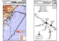
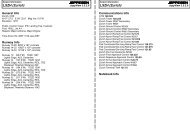
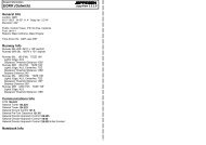
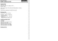
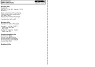
Airport Information<strong>TNCM</strong> (<strong>Princess</strong> <strong>Juliana</strong> <strong>Intl</strong>)JEPPESENJeppView 3.5.2.0General InfoSt Maarten I, ANTN 18° 02.5' W 63° 06.6' Mag Var: 13.9°WElevation: 13'Public, Control Tower, IFR, Landing Fee, Rotating Beacon,Customs availble on a restrcted basisFuel: 100-130, Jet A-1Time Zone Info: Atlantic Time GMT-4:00 no DSTRunway InfoRunway 09-27 7152' x 148' asphaltRunway 09 (94.7°M) TDZE 11'Lights: Edge, REILRight TrafficStopway Distance 394'Runway 27 (274.7°M) TDZE 13'Lights: EdgeStopway Distance 262'Communications Info<strong>Juliana</strong> Tower 118.7<strong>Juliana</strong> Approach Control 128.95Notebook Info
CHANGES: New chart.| JEPPESEN SANDERSON, INC., 2006. ALL RIGHTS RESERVED.CHANGES: New chart.| JEPPESEN SANDERSON, INC., 2006. ALL RIGHTS RESERVED.Licensed to max. Printed on 16 Feb 2008.NOTICE: PRINTED FROM AN EXPIRED REVISION. Disc 01-2008<strong>TNCM</strong>/SXM1 DEC 06 10-9D1. INTRODUCTIONVISUAL DOCKING GUIDANCE SYSTEMS2.2 GENERAL WARNINGThe DGS has built-in features of self-diagnostics and gate area scanning checks to inform theaircraft pilot of problems that could affect the safety of the docking procedure. Refer to"section 4. ABNORMAL CONDITIONS" for futher details on these items.JEPPESENJeppView 3.5.2.02.2 ITEMS TO CHECK BEFORE ENTERING THE STAND AREAAlthough the DGS has built-in features of self-diagnostics and gate area scanning checks, thepilot should always use their judgement of safety should there be any items in the "obstacle free"area not captured by the DGS. In general, the aircraft should be stopped prior to further entryinto the gate area if there is a presence of any object posing a question to the safety of theaircraft or personnel on the ground.2.3 THE SBU MESSAGEST MAARTEN I, NETH ANTILLES(PHILIPSBURG)PRINCESS JULIANA INTLThe Safedock Docking Guidance System (DGS) is an automated "parking aid" system designed tosafely guide the aircraft into gate to its assigned stop-position. It accomplishes this by activelytracking the aircraft while providing the pilot real-time visual feedback of "distance-to-go" andazimuth guidance in relation to the centerline and stop-position.2. SAFETY PROCEDURESIf the pilot is unsure of the information being shown on the DGS Display unit, the aircraftSHOULD BE STOPPED IMMEDIATELY UNTIL further information for clearance HAS BEEN OBTAINED.Upon entry to the gate area, the pilot should make a quick visual check of the gate area andverify that the DGS is displaying the vertical running arrows and correct aircraft type. If thereis any concern in these checks, the aircraft should be stopped until the situation is corrected ormanual guidance is provided. During the aircraft docking, the pilot should follow the guidanceof the DGS while staying alert for any items within his view posing a danger to the aircraft orpersonnel on the ground.GENERAL PRECAUTIONS:THE PILOT SHALL NOT ENTER THE GATE AREA, UNLESS THE DOCKING SYSTEM IS SHOWINGTHE VERTICAL RUNNING ARROWS.THE PILOT SHALL NOT ENTER THE STAND AREA UNLESS THE AIRCRAFT TYPE AND ANY OTHERDISPLAYED INFORMATION IS CORRECT FOR THE AIRCRAFT THEY ARE DOCKING.THE PILOT MUST NOT PROCEED BEYOND THE BOARDING BRIDGE CAB, UNLESS THESE ARROWSHAVE BEEN REPLACED BY THE "CLOSING RATE BAR".The message STOP SBU means that docking has been interrupted due to an unexpected error orhardware malfunction and has to be resumed by manual guidance. DO NOT RESUME DOCKINGUNDER DGS-GUIDANCE UNDER THIS CONDITION.3. AIRCRAFT DOCKING PROCEDUREThe following section is a detailed step-by-step approach to the stages of the docking routineindicating the typical events from start to completion.3.1 START OF DOCKING (SELF-TEST)JEPPESENUpon activating the DGS for aircraft docking, a self-test and calibration checkis performed to confirm docking accuracy. During this time, the display willshow "WAIT".RedLicensed to max. Printed on 16 Feb 2008.NOTICE: PRINTED FROM AN EXPIRED REVISION. Disc 01-2008<strong>TNCM</strong>/SXM1 DEC 06 10-9E3.3 TRACKINGVISUAL DOCKING GUIDANCE SYSTEMSJEPPESENJeppView 3.5.2.0ST MAARTEN I, NETH ANTILLESWhen the DGS "captures" the approaching aircraft, the rolling arrows arereplaced by a "yellow" closing rate bar". At this point, the DGS has capturedthe aircraft and is actively tracking it. The DGS is also in the process of verifyingthe approaching aircraft against that selected (as shown in the display).The "closing rate bar" consists of a centerline indicator showing the aircraftin relation to the target stop-position.3.4 CLOSING RATEDigital countdown begins when the aircraft is 12 meters (or 40 feet) from itsstop position. When the aircraft is within this distance, the "distance-to-go"closing rate indicator decreases by about one LED-row per 1.6 foot or halfmeter of movement.Digital countdown resolution:20 to 2 meters 1 meters2 meters to STOP 0.2 meters40 to 8 feet8 feet to STOP4 feet1 footThe example shows the B747 aircraft 10m from the stop-position slightly offcenterto the left.3.5 ALIGNED TO CENTERWhen aligned to center, the RED direction arrows disappear indicating theaircraft is on center.The example shows the B747 aircraft 8m from the stop-position and on-center.3.6 SLOW DOWNIf the aircraft is approaching faster than the accepted speed, the systemwill show SLOW DOWN as a warning to the pilot.The example now shows the B747 aircraft about 8m from the stop-positionand still on-center yet needing to slow down.3.7 AZIMUTH GUIDANCECenterline guidance countinues to the stop-position.The example shows the B747 aircraft 4m from the stop-position,slightly off-center to the right.3.8 STOP-POSITION REACHEDJEPPESENA flashing RED arrow provides azimuth guidance and indicates the directionthe pilot should steer the aircraft to the centerline.When the aircraft reaches its assigned stop-position, the display willshow STOP with RED lights to each side.(PHILIPSBURG)PRINCESS JULIANA INTLFlashingRed3.2 CAPTURE (INCOMING AIRCRAFT)The rolling arrows indicate that the SAFEDOCK is searching the gate arealooking to "capture" the arriving aircraft.Check that the correct aircraft and sub-type are displayed. If not the dockingmay result in an ID-fail. Following this, the pilot should proceed into the gatearea following the correct lead-in line or centerline.DO NOT PROCEED PAST THE BOARDING BRIDGE CAB IF THE ROLLING ARROWSARE NOT REPLACED BY THE "CLOSING RATE BAR". ALSO, KEEP AWARE OF ANYVISIBLE ITEMS POSING A DANGER TO THE SAFETY OF THE AIRCRAFT ORPERSONNEL ON THE GROUND.RedYellow3.9 DOCKING COMPLETEDAfter the aircraft is completely stopped, the OK message will be displayed.3.10 OVERSHOOT (TOO FAR)If the aircraft overshoots the stop-position, a TOO FAR will be displayed.Note: The overshoot condition is usually triggered by the aircraft goingmore than 0.5m past the target stop-position. This may or may not createa concern for the boarding bridge to accommodate the overshoot position.The ground crew will be alerted to the situation by this message and thendetermine if the aircraft needs to be pushed back.
CHANGES: New chart.| JEPPESEN SANDERSON, INC., 2006. ALL RIGHTS RESERVED.CHANGES: New chart.| JEPPESEN SANDERSON, INC., 2006. ALL RIGHTS RESERVED.Licensed to max. Printed on 16 Feb 2008.NOTICE: PRINTED FROM AN EXPIRED REVISION. Disc 01-2008<strong>TNCM</strong>/SXM1 DEC 06 10-9FJEPPESENVISUAL DOCKING GUIDANCE SYSTEMSJEPPESENJeppView 3.5.2.0ST MAARTEN I, NETH ANTILLES(PHILIPSBURG)PRINCESS JULIANA INTLLicensed to max. Printed on 16 Feb 2008.NOTICE: PRINTED FROM AN EXPIRED REVISION. Disc 01-2008<strong>TNCM</strong>/SXM1 DEC 06 10-9GJEPPESENJEPPESENJeppView 3.5.2.0ST MAARTEN I, NETH ANTILLESVISUAL DOCKING GUIDANCE SYSTEMS(PHILIPSBURG)PRINCESS JULIANA INTL3.11 CHOCKS ON MESSAGEThe "Chocks On" is displayed to indicate that the chocks have been set inplace to the aircraft wheels. This feature is available via button press on theOperator's Panel to provide or supplement the ground operator's responsibilityto provide the status message to the pilot.3.12 STOP SHORTIf the aircraft is stopped short and at a standstill but has not reachedthe intended stop position, the message STOP OK will be shown aftera while.4.3 BAD WEATHER CONDITION (DOWN-GRADE)During heavy fog, rain or snow, or any low visibility condition, the docking systemgoes into downgrade mode.When operating at this mode, the display will deactivate the floating arrows andalternate between 'DOWN GRADE' and aircraft type. The DGS will continueoperation but with reduced aircraft slow-down speed.This message will be replaced by the closing rate bar, as soon as the systemdetects and captures the approaching aircraft.THE PILOT MUST NOT PROCEED BEYOND THE BRIDGE CAB UNLESS THE "DOWNGRADE" TEXT HAS BEEN REMOVED AND THE DGS INDICATES IT IS TRACKINGTHE AIRCRAFT INTO THE GATE AREA.4.4 AIRCRAFT VERIFICATION FAILURE4. ABNORMAL CONDITIONSIf an object is blocking the view from the SAFEDOCK DGS laser-scanning unit toward the stopposition of the selected aircraft type, the system will be unable to perform the docking procedure.When an object is detected between the laser scanning unit and the stop position for at least tenseconds, the DGS will halt the docking procedure and display a GATE BLOCK warning message.When the blocking object is removed, the docking procedure will be resumed. The same applieswith an object detected in the "apron scan" area whereas the DGS will display an "APRONBLOCK" warning message. Note that the "apron scan" feature only covers the pilot's blind spotarea when the aircraft requires a right turn into the gate. See further details later in this sectionfor more info on this.If an unrecoverable error occurs during a docking procedure, a SBU (Safety Back Up) conditionexists. In this case an alternate method to guide aircraft to the stop position must be used, asthe docking procedure cannot be completed. SBU stop conditions are:(a)(b)(c)A hardware failure.Aircraft more than 3.5 degrees off centerline and less than 2m (6.5ft) to the stoppositionView from Laser scanning unit to aircraft blocked with less than 2m (6.5ft) to thestop-position.WARNING: An object must never be placed in front of the DGS unit and closer than 1.5 meters(or 5 feet) to the laser window. Such an object would violate proper docking performance!Other abnormal or non-typical conditions that may occur are as follows:4.1 WAITThe WAIT message is displayed for various reasons and may be followed withfurther info. In general, it is an indication to the pilot that the DGS is not yetready to guide or continue guiding the aircraft into the gate. The reasons mayvary from startup self-testing, lost track of the aircraft, or large obstaclesor personnel in the critical docking area or obstacle free zone. Basically,something that may compromise the docking or a safety concern.When the problem is resolved or the blocking object has moved from thecritical docking area, docking may continue. The DGS display must also showthe "closing rate" bar and that it is back in docking mode AND tracking theaircraft.THE PILOT MUST NOT PROCEED BEYOND THE BOARDING BRIDGE CAB UNLESSTHE "WAIT" MESSAGE HAS BEEN REMOVED AND THE DGS INDICATES IT ISTRACKING THE AIRCRAFT INTO THE GATE AREA.4.2 BRIDGE NOT IN POSITIONThe "BR IN" message occurs when the Passenger Boarding Bridge (PBB) isinterlocked to the DGS and is NOT safely stowed or parked in the properparking position (or a defect in the wiring).This message with the red-LEDs is indication to the pilot that aircraft dockingMUST wait until ground personnel move the PBB into safe position away fromthe critical docking area.THE PILOT MUST NOT PROCEED BEYOND THE BOARDING BRIDGE CAB UNLESSTHE "BR IN" MESSAGE HAS BEEN REMOVED AND THE DGS INDICATES IT ISTRACKING THE AIRCRAFT INTO THE GATE AREA.After capture of the aircraft, the DGS checks its geometry against a stored profile.If, for any reason, aircraft verfication is not confirmed at 12 meters (or 40 feet)before the target stop-position, the display will show STOP followed by ID FAIL(alternating on the upper row of the display).If the DGS is re-activated for the same aircraft type, docking can resumewithout aircraft verification. Note that such re-activation should be doneonly after the ground crew has verfied the correct aircraft type.THE PILOT MUST NOT PROCEED BEYOND THE BOARDING BRIDGE CAB WITHOUTMANUAL GUIDANCE, UNLESS THE DOCKING HAS BEEN RE-ACTIVATED ANDTHE DGS INDICATES IT IS TRACKING THE AIRCRAFT INTO THE GATE AREA.4.5 GATE BLOCKEDIf an object is found blocking the view from the DGS to the planned stopposition for the aircraft, the docking procedure will be halted with a GATEBLOCK message. The docking procedure will resume as soon as the blockingobject has been removed.The "Gate Block" area covers the general scanning area of the approachingaircraft and where the aircraft body will be when parked as well as the areabetween the DGS and those points. In general, the message is provoked bylarge obstacles interfering this scanning area. This feature does not look forsmaller interfering items on the apron.THE PILOT MUST NOT PROCEED INTO THE GATE AREA WITHOUT MANUALGUIDANCE, UNLESS THE "WAIT/GATE/BLOCK" MESSAGE HAS BEEN REMOVEDAND THE DGS INDICATES IT IS TRACKING THE AIRCRAFT INTO THE GATE AREA.4.6 VIEW BLOCKEDIf the view towards the approaching aircraft is hindered, for instance by dirton the window, the DGS will report a View Blocked condition. If the system isable to see the aircraft through the dirty window, the message will be replacedwith a closing rate display.The difference between the "View Block" and the "Gate Block" feature is thatthe "View Block" feature looks for interference within 2m of distance from thelaser and the "Gate Block" feature looks for interference past this distance.THE PILOT MUST NOT PROCEED BEYOND THE BOARDING BRIDGE CAB WITHOUTMANUAL GUIDANCE, UNLESS THE WAIT MESSAGE HAS BEEN REMOVED AND THEDGS INDICATES IT IS AGAIN TRACKING THE AIRCRAFT INTO THE GATE AREA.4.7 TOO FASTIf the aircraft approaches with a speed higher than the docking system canhandle, the message STOP (with red squares) and TOO FAST will be displayed.The aircraft docking must be re-started or the docking procedure completed bymanual guidance.THE PILOT MUST NOT PROCEED BEYOND THE BOARDING BRIDGE CAB WITHOUTMANUAL GUIDANCE, UNLESS THE DOCKING HAS BEEN RE-ACTIVATED AND THEDGS INDICATES IT IS TRACKING THE AIRCRAFT INTO THE GATE AREA.
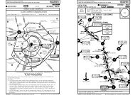
Licensed to max. Printed on 16 Feb 2008.NOTICE: PRINTED FROM AN EXPIRED REVISION. Disc 01-2008<strong>TNCM</strong>/SXM1 DEC 06 10-9H4.8 ANOMALOUS ERROR, SBU-STOPAny anomalous or unrecoverable error during the docking procedurewill generate a SBU condition. A manual backup procedure must beused for docking guidance.Note: An SBU-Stop may be followed by another error related to ahardware failure or other anomalous event.4.9 ERROR CONDITIONJEPPESENJEPPESENJeppView 3.5.2.0ST MAARTEN I, NETH ANTILLESVISUAL DOCKING GUIDANCE SYSTEMSTHE PILOT MUST FOLLOW MANUAL GUIDANCE INTO THE GATE WHENTHE DGS DISPLAY IS IN THIS CONDITION.(PHILIPSBURG)PRINCESS JULIANA INTLBRIEFING STRIP TMLicensed to max. Printed on 16 Feb 2008.NOTICE: PRINTED FROM AN EXPIRED REVISION. Disc 01-2008JEPPESENJeppView 3.5.2.0<strong>TNCM</strong>/SXMJEPPESEN ST MAARTEN I, NETH ANTILLES(PHILIPSBURG)PRINCESS JULIANA INTL 13-1 27 JUL 07VOR DME Rwy 09VORPJM113.0*JULIANA Approach128.95 118.7Final Minimum AltMDA(H)Apch Crs D7.02130'(2117')600'(587')Apt Elev 13'096^*JULIANA TowerMISSED APCH: Turn RIGHT to 160^ heading, climb to 1500' withinD10.0, then turn RIGHT, return to PJM VOR climbing so asto reach the VOR at or above 2500'.Alt Set: hPa Apt Elev: 0 hPa Trans level: FL 65 Trans alt: 5000'1. Landing Rwy 27 at night prohibited, VMC by day. 2. Final approach track is offset3^ from runway centerline.090^3900'2400'360^MSA PJM VORAny error that occurs during the DGS operation will generate anERROR message with an error code in the main display. Errors thatoccur during aircraft docking may be proceeded with an "SBU"message.THE PILOT MUST FOLLOW MANUAL GUIDANCE INTO THE GATEWHEN THE DGS DISPLAY IS IN THIS CONDITION.4.10 EMERGENCY STOPIf the Emergency Stop button is pressed (by the ground operator),the display will show STOP with RED lights to each side.The ground crew may activate this button to indicate a dangerouscondition that requires aircraft motion to STOP and NOT continue itsapproach into the gate.THE PILOT SHOULD STOP THE AIRCRAFT AT ANY TIME THE STOPMESSAGE IS DISPLAYED DURING DGS DOCKING GUIDANCE THENFOLLOW MANUAL GUIDANCE.18-0518-009 DME ArcD7.0[FF~9]096^D7.0ST MAARTEN284 PJDD2.0[MA~9]174'HazardBeaconPJMST MAARTEND113.0 PJM318^128^974'HazardBeacon160^ hdg1538'886'FRENCH ANTILLES1122' NETH. ANTILLES972' 1119'Hazard574'BeaconHazardBeacon308^722'HazardBeacon393'HazardBeacon4.11 NON-OPERATIONAL CONDITIONShould there be a hardware failure that interferes with the DGSability to operate, the display will go blank with RED lights to eachside. In such cases, the DGS cannot be used until the hardwarefailure has been resolved.THE PILOT MUST FOLLOW MANUAL GUIDANCE INTO THE GATE WHENTHE DGS DISPLAY IS IN THIS CONDITION.4.12 NO POWER (OR POWER FAILURE)When the DGS is powered-Off, or in the case of a power failure, thedisplay will be shown as completely black. Until power is restored,any aircraft shall be marshalled-in or towed-in to the gate.THE PILOT MUST FOLLOW MANUAL GUIDANCE INTO THE GATE WHENTHE DGS DISPLAY IS IN THIS CONDITION.17-5563-20MAP at D2.09 DME Arc2130'D7.0[FF~9]4.9 NMto MA~9096^[2.87^]STRAIGHT-IN LANDING RWYMDA(H) 600'5.0Gnd speed-Kts 70 90 100 120 140 160Descent Gradient 5.0% orDescent angle354 456 506 608 709 810[2.87^](587')63-1009D2.0[MA~9]318^VOR 128^2500'3500'1.9 APT.REILPAPI-L[TCH 50']13'RT63-00308^308^160^hdgCIRCLE-TO-LAND1 Min1500'AABC4500mBCNAPANS OPSDDCHANGES: New chart.| JEPPESEN SANDERSON, INC., 2006. ALL RIGHTS RESERVED.CHANGES: None.| JEPPESEN SANDERSON, INC., 2000, 2007. ALL RIGHTS RESERVED.
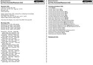
Licensed to max. Printed on 16 Feb 2008.NOTICE: PRINTED FROM AN EXPIRED REVISION. Disc 01-2008<strong>TNCM</strong>/SXMApt Elev13'N18 02.5 W063 06.627 JUL 07JEPPESEN13-1Traffic entering, transiting or operating withinTMA contact <strong>Juliana</strong> Approach on 128.95.81'*JULIANA Tower 118.7FRENCH ANTILLESJEPPESENJeppView 3.5.2.0ST MAARTEN I, NETH ANTILLES(PHILIPSBURG)PRINCESS JULIANA INTL18-03 63-0763-06 18-03Rwy 27 left hand traffic pattern when in use,however right hand turn after take-offon request only.BRIEFING STRIP TMLicensed to max. Printed on 16 Feb 2008.NOTICE: PRINTED FROM AN EXPIRED REVISION. Disc 01-2008<strong>TNCM</strong>/SXMPRINCESS JULIANA INTLVORPJM113.020 JUN 03*JULIANA Approach13-2JEPPESENJeppView 3.5.2.0ST MAARTEN I, NETH ANTILLES(PHILIPSBURG)CAT A & B VOR Rwy 09*JULIANA Tower128.95 118.7FinalApch Crs096^JEPPESENNo FAFMDA(H)Refer toMinimumsApt Elev 13'MISSED APCH: Turn RIGHT to heading 180^ climbing to 1500'within 10 NM. Return to PJM VOR so as to reach the VOR at orabove 2500'.Alt Set: hPa Apt Elev: 0 hPaTrans level: FL 65Trans alt: 5000'1. Landing Rwy 27 at night prohibited, VMC by day. 2. Final approach track is offset3^ from runway centerline.090^3900'2400'360^MSA PJM VOR132'ControlTowerNETHERLANDS ANTILLES13^W85'394'120mStopway18-10262'80mStopway09095^Elev 13'69'AA-BVORNDBBBldgAreaCDARP7152'2180mBldg AreaAll propeller driven general aviation aircraftshall make use of the general aviation rampvia taxiway DELTA unless otherwise instructedby ATC.Elev 8'All jet aircraft landing Rwy 09 when usingmid-field turning bay for 180^ turn andHazard Beaconbacktrack shall make all turns to the right.174'All jet aircraft B767 category and heavier18-02 landing Rwy 09 shall roll out to the end18-02182'of the runway, make use of the turningbay and make all turns to the right.Rwy 09 right hand traffic pattern when in use,however left hand turn after take-off onFeet 0 500 1000 1500 2000 2500 3000request only by day in VMC to aircraft withmaximum take-off mass of 15,432lbs (7000kg) Meters 0 200 400 600 800 1000or less, excluding turbojet aircraft.63-06EFG27275^18-00096^ST MAARTEN284 PJD174'HazardBeaconST MAARTEND113.0 PJM288^128^3500'974'HazardBeacon180^hdg1122'308^1391'722'HazardBeacon393'HazardBeacon886'FRENCH ANTILLESNETH. ANTILLES972'1119'Hazard574' BeaconHazardBeaconADDITIONAL RUNWAY INFORMATIONUSABLE LENGTHSLANDING BEYOND09111 & 2Eng3 & 4EngRWY27MIRL REIL PAPI-L (angle 3.0^)MIRLLanding Rwy 27 at night prohibited, VMC by day.Rwy 27300'- 4500mCHANGES: Stopways added, notes.TAKE-OFFRwy 09ThresholdRight Hand Turn MANDATORY.Hazard Beacons on Hills to theEast Must be Visible1200'- 4500mGlide SlopeTAKE-OFFWIDTH148'45m| JEPPESEN SANDERSON, INC., 2000, 2007. ALL RIGHTS RESERVED.PANS OPS63-2063-101500'3 MinMAP at VORSTRAIGHT-IN LANDING RWYCAT A: 470'(457')MDA(H)CAT B: (617')630'A4500mBCNOT APPLICABLEDCHANGES: New chart format.096^09288^VOR2500'ABCDAPT.13'REILPAPI-L63-00CIRCLE-TO-LANDNA1500'| JEPPESEN SANDERSON, INC., 2003. ALL RIGHTS RESERVED.RTto180^hdg
BRIEFING STRIP TMLicensed to max. Printed on 16 Feb 2008.NOTICE: PRINTED FROM AN EXPIRED REVISION. Disc 01-2008<strong>TNCM</strong>/SXMPRINCESS JULIANA INTLVORPJM113.020 JUN 03*JULIANA Approach13-3Alt Set: hPa Apt Elev: 0 hPaTrans level: FL 65Trans alt: 5000'1. Landing Rwy 27 at night prohibited, VMC by day. 2. Final approach track is offset3^ from runway centerline.JEPPESENJeppView 3.5.2.0ST MAARTEN I, NETH ANTILLES(PHILIPSBURG)CAT C & D VOR Rwy 09*JULIANA Tower128.95 118.7FinalApch Crs096^No FAFMDA(H)Refer toMinimumsApt Elev 13'MISSED APCH: Climb STRAIGHT AHEAD on 096^ to 2500' within10 NM. Then return to the PJM VOR.18-10JEPPESEN090^3900'2400'360^MSA PJM VORBRIEFING STRIP TMLicensed to max. Printed on 16 Feb 2008.NOTICE: PRINTED FROM AN EXPIRED REVISION. Disc 01-2008<strong>TNCM</strong>/SXMPRINCESS JULIANA INTL20 JUN 03*JULIANA ApproachAlt Set: hPa Apt Elev: 0 hPaTrans level: FL 651. Landing Rwy 27 at night prohibited, VMC by day.JEPPESENJeppView 3.5.2.0ST MAARTEN I, NETH ANTILLES(PHILIPSBURG)LOCATOR Rwy 09*JULIANA Tower128.95 118.7LCTRFinalMDA(H)PJDApch CrsNo FAFApt Elev 13'284 091^620'(607')MISSED APCH: Upon reaching MDA(H) immediately turn RIGHTclimbing on 180^ heading to 1500' within 10 NM, return toreach PJD Lctr at 2500'.18-10JEPPESEN16-1Trans alt: 5000'090^3900'2400'360^MSA PJD Lctr18-00ST MAARTEN284 PJDPJMST MAARTEND113.0 PJM308^174'HazardBeacon974'HazardBeacon308^1391'096^ 096^128^3500'1122'722'HazardBeacon393'HazardBeacon886'FRENCH ANTILLESNETH. ANTILLES972' 1119'Hazard574' BeaconHazardBeacon18-00046^ST MAARTEND 113.0 PJM091^226^271^174'HazardBeaconST MAARTENPJD 284 974'HazardBeacon180^ hdg091^393'HazardBeacon271^722'HazardBeacon1391'886'1122'FRENCH ANTILLESNETH. ANTILLES972'1119'HazardBeacon574'HazardBeaconPANS OPSMAP at VORABCD63-20CHANGES: New chart format.1 Min45 SecSTRAIGHT-IN LANDING RWYCAT C: 950'(937')MDA(H)CAT D: (957')970'NOT APPLICABLE4500m1500'096^0963-10308^VOR2500'ABCDAPT.13'REILPAPI-LCIRCLE-TO-LANDNA63-002500'on 096^| JEPPESEN SANDERSON, INC., 2003. ALL RIGHTS RESERVED.PANS OPSABCD63-207 NMCHANGES: New chart format.1500'STRAIGHT-IN LANDING RWY4500m091^MDA(H) 620'(607')63-1009271^Lctr091^091^2500'APT.ABCD13'271^271^3500'REILPAPI-LCIRCLE-TO-LANDNA63-001 Min1500'180^hdg| JEPPESEN SANDERSON, INC., 2003. ALL RIGHTS RESERVED.RTto