Download Barton 7000 Gas Turbine Meter ... - Proflow Systems
Download Barton 7000 Gas Turbine Meter ... - Proflow Systems Download Barton 7000 Gas Turbine Meter ... - Proflow Systems
- Page 2 and 3: OperationAs gas passes over the dif
- Page 4: MEASUREMENT SYSTEMSDimensionsFlange
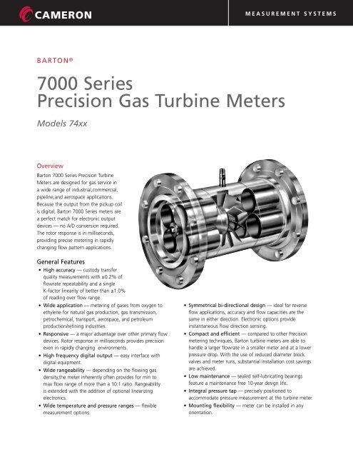
OperationAs gas passes over the diffuser section, it is accelerated onto amulti-blade turbine rotor. The rotor speed is proportional tothe volumetric flowrate. As the rotor turns, a reluctance typepickup coil (mounted on the meter) senses the passage ofeach blade tip and in-turn generates a sine wave output witha frequency directly proportional to the flowrate. Additionalcoils can be added for redundancy or flow direction sensing.The pickup coil can drive a variety of instruments, including,totalizers, pre-amplifiers, or flow computers/RTUs. Preamplifiersare used to transmit the coil signal over extendeddistances to remote mounted instruments. All turbineinstruments can be local or remote mounted and are availablewith intrinsically safe or explosion/flame proof or weatherproofapprovals.Model SelectionActual FlowratesModelNumber7400 Model Selection (Actual Flowrate)BodySizeMinimum Repeatable Rated Max.inmmACFM0.25lb/ft3(4kg/m3)ACMH0.5lb/ft3(8kg/m3)ACFMACMH2.0lb/ft3(32.08kg/m3)ACFMACMHACFMACMHExtended(1)R angeACFMACMHNominal <strong>Meter</strong> Output(±5.0%)Pulses/ft3Pulses/M374863/4 201.4 2.371.0 1.690.5 0.856.7 11.3 7.4 12.5 21600762800240074501 252.7 4.581.9 3.221.0 1.691525.5 1728.0 10700377900267574751 253.2 5.422.3 3.901.252.122237.4 2440.7 7400261300271574011 254.8 8.143.5 5.931.7 2.8850855593.4 3350118300279074461-1/2 4012.5 21.198.5 14.414.2 7.12125212138234170060000354074022 501932.2014.5 24.586.7 11.3620034022037474026100246574033 805593.223966.1018.7 31.6956095061610451906000177074044 10082138.9 59100.0 3152.548501445935159080300011302)7406A(/ 65 150130220.3 92155.9 4678.0 135023001485252535125080074066 150215364.4 158267.8 73123.7 220037402420411022100080074088 200340576.3 243411.9 117198.3 35005950385065409 400525741010250550932.2 390661.0 193327.1 580098556380108405 1805007412123008501440.7 6101033.9 300508.5 9000152909900168203 105450Notes:( 1) Operating continuously in theE xtended Rangewill reduce the bearing life by approximately 25%( 2) 7406A(6" [150 mm] end connections)RatedMaxFreq.(Hz)Calculating <strong>Gas</strong> <strong>Turbine</strong> <strong>Meter</strong> SizeFor calculating gas turbine meter size for conditions otherthan those given in Selection Table (actual flowrates) use thefollowing method (per AGA-7):(1) Q f =P bT bx Q h xT fP fwhere:Q f = quantity rate of flow at line conditionsP b = atmospheric pressure or pressure at base conditionsT b = absolute temperature at base conditionsQ h = quantity rate of flow at reference (base) conditionsT f = absolute temperature at line conditions= absolute static pressureP fγ bP f(2) γ = x x(3)P bT bT fwhere:γ = density at flowing conditions= density at base conditionsγ bQf min= Qf ref xγ refγwhere:Qf min = rate of minimum linear flow at line conditionsQf ref = minimum flowrate from flowrate table on page 2from column selected for γ ref2
MEASUREMENT SYSTEMSSpecificationsPressure Rating:End ConnectionsFlangeThread(up to 4-inch)Bearing TypeMaterialsRotor BladesBearingsBody/FlangesInternalsThe following are standard pressure ratingsmanufactured to ASME B31.1 and B31.3 andEuropean PED standards. Higher pressure ratingsare also available. For flanged meters the pressurerating will be the lower of the flange rating or themeter body.Connection size(inches)< 111-1/222-1/234PSI5000440032002650225016501350Bar34530322018315511493Pressure ratings for 6”, 8”, 10”, 12” meters arespecific to the application and are dependentflange connection, process fluid, processconditions, body material and construction detail.ANSI B16.5 (BS1560); DIN (BS4504)BSPP;UNF;NPTOthers to special order.Ball430 Stainless Steel440C Stainless Steel,with dry lubricantimpregnated, Rulon® ball separators316 Stainless Steel; Carbon Steel on sizes4"(102 mm) and larger;316 Stainless SteelOthers to special orderTemp. Range* Standard: -100° F to +500° F (-75° C to +260° C)Optional: -450° F to +572° F (-260° C to +300° C)Pressure Drop 1.8 psi (0.12 bar) at maximum flowrate(based on air w/density of 1.0 lb/ft3 (16 kg/m3)for specific flow rate values, see Selection charts).<strong>Gas</strong> Density 0.08 to 4.5 lb/ft3 ) 1.25 to 73 kg/m3Other densities availablePerformance & CalibrationThe average K-factor for each turbine is determined at thefactory by using water as the calibration media. Performed atsix different flow rates, this multi-point calibration verifieslinearity and repeatability over a limited range of the metercapacity. The average K-factors derived in water as comparedto gas are within 1% deviation of each other. A watercalibration is also an effective method to validate a meter inthe field. Consult factory for field water calibration procedures.<strong>Gas</strong> calibrations are comparatively expensive but can bevaluable in the following instances:• When verifying the low end capacity of the meter as wouldbe required to implement electronic linearization.• For testing of upper end capacity of the meter. Full capacitytesting can rarely be performed on water due to pressuredrop issues.<strong>Gas</strong> calibration should be performed on a gas density similarto the process fluid density.<strong>Meter</strong> performance specified in this bulletin is based onhistorical gas calibration performed at independent world classcalibration facilities using gas media. Not included in ouraccuracy statement is any systemic bias the calibration lab mayhave. Repeatability is limited by gas laboratory precision but inwater is typically ±0.02%.Linearity indicates that no data point will exceed the averageof all the data points within the linear meter capacity (normally10 to 100% capacity) as per ISA standard RP31.1. Installationwith straight pipe per American <strong>Gas</strong> Association report #7 isrequired to achieve the specified linearity.All meters should be installed with upstream filtration toisolate the meter from contamination and damage from liquidsor solids.OutputTypeVoltageare:FrequencySinewavevaries w/meter size and flowrate. Typical values20 - 500 mV rms on 3/4‘‘ (20 mm)and 0.2 – 5V rms on 12’’ (300 mm)Proportional to flowNote: The electronic equipment mounted directly on the meter can beexposed to temperatures from -40° F (-40° C) to +160° F (+71° C). Usemounting extensions or remote mounts for higher process temperatures.3
MEASUREMENT SYSTEMSDimensionsFlanged <strong>Meter</strong>UNF <strong>Meter</strong>Screw-end <strong>Meter</strong>2-inch (50 mm)MaximumPickupCoil3/4" MNPTCoil Boss2-inch(50 mm)MaximumPickupCoil3/4" MNPTCoil Boss2-inch(50 mm)MaximumPickupCoil3/4" MNPTCoil BossB(diameter)B(diameter)60°FNPTA(Face to Face)FNPTA(End to End)FNPTA(End to End)RatingBS 1560(ANSI)BS 4504(DIN)BS 10Model748674507475740174467402740374047406740874107412Flanged Ends Face-to-FaceAAUp to ANSI 900 &ANSI 600 1500Up to PN 64 PN 100 & 160Up to Table RInmm5-1/25-1/25-1/25-1/266-1/2101214162024140140140140152165254305356406508610Tables S& TInmm788899101214162024178203203203229229254305356406508610AANSI 2500PN 250 & 320In788899111216182224mm178203203203229229279305406457559610UNFBModel Thread A(diameter)No. UNFinmminmm74861-1/16"-123-1/4 82.5 1-1/4 3274501-5/16"-123-1/2 891-1/2 4074751-5/16"-123-1/2 891-1/2 4074011-5/16"-123-1/2 891-1/2 4074461-7/8"-124-3/8 1112-1/4 5774022-1/2"-124-3/4 120.5 2-3/4 70Integral Pressure TapNominal Pipe Sizes(inches)3/4'' through 2-1/2''3'' through 8''10'' and 12''Tap Size(FNPT)1/8"1/4''1/2''Screwed EndsModel ThreadANo. BSPP/NPT inmm74863/4 3-1/4 8374501 3-1/2 8974751 3-1/2 8974011 3-1/2 8974461-1/2 4-3/8 11174022 4-3/4 12174033 1025474044 12305Companion ElectronicsThe following NuFlo electronic instruments are availableto complement the <strong>7000</strong> Series <strong>Turbine</strong> <strong>Meter</strong>:• 818A/818EU Preamplifiers• MC Series Rate Totalizers• Scanner Family of Flow ComputersPerformance (Typical)<strong>Gas</strong> <strong>Turbine</strong> <strong>Meter</strong>Performance Curve (Typical)Flow Range atDesignatedLinearityVoltage into 10kΩ (mV RMS)Freq. Output (Hz)Press. Drop (PSID)Note: Voltage not necessarilyproportional to flow rate.0 20 40 60 80 100%Flow RateMEASUREMENT SYSTEMSFormerly: NuFlo Measurement <strong>Systems</strong> • <strong>Barton</strong> Instrument <strong>Systems</strong> • Caldon, Inc.HOUSTONHEAD OFFICE281.582.9500NORTHAMERICA1.800.654.3760ms-us@c-a-m.comASIAPACIFIC603.2287.1039ms-asiapacific@c-a-m.comEUROPE,MIDDLE EAST& AFRICA44.1243.826741ms-uk@c-a-m.comUSA • CANADA • UK • SCOTLAND • CHINA • UAE • ALGERIA • MALAYSIA • SINGAPORE • www.c-a-m.com/floTUR-7400 NF00036 0709


