warning - Romstal
warning - Romstal
warning - Romstal
- No tags were found...

You also want an ePaper? Increase the reach of your titles
YUMPU automatically turns print PDFs into web optimized ePapers that Google loves.
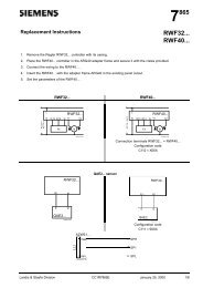
VK41../VK81..SERIESGAS CONTROLS FOR COMBINED VALVE AND IGNITION SYSTEMAPPLICATIONPRODUCT HANDBOOKThe Combined Valve and Ignition (CVI) system has beendeveloped for application in gas fired domestic central heatingboilers, combi boilers and warm air furnaces or water heaterappliances with an automatic ignition system.For this system, the VK41../VK81.. series gas controls havebeen designed to have the S4565/S4575/S4585 seriesignition control attached directly on to the valve.The combined system then provides programmed safe lightup, flame supervision and regulation of gas flow to the mainburner and/or pilot burner of the appliance.The VK41.5/VK81.5 series gas controls (without pilot outlet)can also be used alone in direct burner ignition applications.A plug (order number 45.900.441- ) with integrated rectifiercircuit then has to be used on the gas control.Subject to change without notice. All rights reserved.GeneralContentspageDescription ...................................................................... 2Features .......................................................................... 3Dimesional ..................................................................... 4Application ...................................................................... 6TechnicalSpecifications .................................................................. 7Electrical data .............................................................. 10Capacity curves ....................................................... 13-23Performance characteristics .......................................... 25Installation ..................................................................... 27Electrical connections and wiring .................................. 30Adjustments and checkout ............................................ 31Construction and working principles ............................. 32VariousQuality assurance statement ......................................... 35Standards and approvals .............................................. 36Ordering information ..................................................... 37Replacement parts and accessories ............................. 381 EN2R-9004 0311R16-NE
DESCRIPTIONValvesThe Combined Valve and Ignition (CVI) system controls andperforms all the functions required for safe ignition, flamesupervision and for safely regulating the gas flow to the pilotand/or main burner.The CVI consists of a gas valve of the VK41../VK81.. seriesand a dedicated ignition control of the series S4565/S4575/S4585 which is connected directly on to it.The gas control comprises a standard body to which a rangeof features can be factory included to give various functionaloptions. These functional options include: servo pressureregulation, throttle valve regulation, fully adjustable SOFTLITE,gas/air control 1:1 or amplified, electrical high-low ormodulating control to fulfil the complete range of controlapplications.The gas control has a first direct on/off operator for openingthe safety valve of class A or B according to EN 161 and asecond electric on/off servo operator for control of the mainvalve of class B,C or J according to EN 161 (for explanationclass J, see chapter Standards and approvals page 36).The pressure regulator is in accordance with class Brequirements of EN 88The gas control can handle the three gas families,manufactured gas, natural gas and LP gas.GeneralAll measurements are carried out under standard conditionslisted below unless otherwise is indicated.Standard conditions• P inlet 25 mbar nominal pressure, dry air of 20°C• P ambient 1013 mbar• T ambient 20°C• Outlet orifice 2.8 mm• Flow indication in m 3 / h• Recording of outlet pressure with a transducer connectedto a 1 / 2 ” pipe with a length of 10 times the diameter of thepipe with a short hose at a length of 5 times the diameter ofthe pipe.• Nominal voltage• Upright position, i.e. the position when the operators are ontop.EN2R-9004 0311R16-NE 2
FEATURESGeneral• All burner control safety functions concentrated in one reliableand optimized system.• Specially designed to provide the optimum system solutionin gas appliances with a DBI or IP system to light the mainburner.• Both gas control and ignition control incorporate timeproven design concepts assuring reliability.• ON/OFF control of main burner by electric operator andelectric servo operator directly energized from ignition control.• Easy assembly of ignition control on gas control by pluggingit on from the top.• Mounting orientation may be within 90_ in any directionfrom the electric on/off operator upright position.Gas control• Inlet ∅ 18.6 mm and outlet ∅ 18.6 mm connections arestraight through and can receive flanges.• The following closing force models are available: B + J;B + C; B + B; A + J; A + C; A + B.• Servo pressure regulator provides stable outlet pressure.• Pressure feedback ensures constant burner pressure inrelation to combustion chamber pressure.• All adjustments are accessible from the top.• 9 mm diameter pressure taps on top face for checking inletand outlet pressure• An internal fine mesh screen is incorporated at the inlet ofthe gas control. This screen is not removable for cleaning.• An outlet screen is optional.• Two mounting holes for self tapping screws are at the bottomof the gas control for rigid attachment to the appliance.Gas connection options• Internal thread (ISO 7-1):3 / 8 ” inlet and 3 / 8 ” end outlet; body length 115 mm.1 / 2 ” inlet and 1 / 2 ” end outlet; body length 115 mm.1 / 2 ” NPT inlet and flanged end outlet; body length 115 mm.• External thread (ISO-R228):1 / 2 ” inlet and 1 / 2 ” end outlet; body length 135 mm1 / 2 ” inlet and standard flanged end outlet;body length 120 mm3 / 4 ” inlet and 3 / 4 ” end outlet; body length 135 mm3 / 4 ” inlet and standard flanged end outlet;body length 120 mm3 / 4 ” inlet and standard flanged side outlet;body length 120 mm• Side outlet option for both main and pilot gas.• The side outlet for pilot and main gas can only be connectedto a flanged burner manifold.• Pilot gas connection for tubing with 4 mm outer diameter islocated at the outlet end of the gas control.• Pressure feedback fittings for 4 or 6 mm silicon tube can bemounted.Electrical connection options• The appropriate ignition control can be connected to thevalve by plugging it on.• Wired plug (IP 44) for connection with a remote ignitioncontrol.• Rectifier plug (IP 44) for use with any standard DBI ignitionsystem.• 24 Volt versions available for use in conjunction with otherignition controls than S4565/S4585 series.Functional options• Fast open and SOFTLITE versions• Fully adjustable SOFTLITE option to facilitate the smoothlight-up of burner and for changing over from one gas toanother.NOTE: SOFTLITE opening is not always available when thesecond valve is classified as a class B valve.• 100 mbar inlet pressure versions available on request• Throttle valve versions• Electrical modulation (Modureg) or CVI-m.• Electrical High-Low control.• Pilot outlet for IP system• Gas/Air ratio version available.3 EN2R-9004 0311R16-NE
DIMESIONAL DRAWING STANDARD CONNECTIONM5 x 0.8(3)6 mm full thread24.136.79.1"0"-ring sizeØ 15.55 x Ø 15.5568.394.813.4STEPSide outlet1Pressure tap (2)Adjustable softlite24.96.3 terminal (2)184Throttle7384.5115684.5VK.1..M/N(Modureg)Outlet 1/2" ISO7-1or 3/8" (optional)113Inlet 1/2" ISO7-1 or93* 3/8" (optional)Pilot outlet M8 x 1-6Hfor 4 mm tubing29.336.724246.3 terminal (3)184VK.1..P/Q(High/Low)80VK.1..A/C(Standard regulator)70VK.1..E/T(Throttle)STEP34.3Hole Ø 2.6 to connectignition control62INOUT21.924Side outlet(Optional)68.3Earth terminalMolex 1.1 square pin header(mating connectors 3001 series)9136.7Flange thread 1/2"or 3/8" ISO7-112.516 mm full thread 25VK.1..B/D(Blank plate)17M4x0.7-6H(8)6 min full thread12The cross hatched areais sealing face withoutimperfections183064.72412Ø 18.6243232Mounting hole (2) fortapping screws 3.9DIN 7970811510529.4Tolerances accordingto ISO 2768 mK* For 220 V DBI only2424V1 V2EN2R-9004 0311R16-NE 4
DIMESIONAL DRAWING EXTERNAL THREAD CONNECTIONHole Ø 2.6 to connectignition control61.694.8INMINV1 V2Earth terminal84.5115Molex 1.1 square pin header(mating connecters 3001 seriesInlet91G 1/2" orG 3/4"36.720.711.930Mounting hole (2) for tappingscrews 3.9 according DIN 79701530±0.5158±0.5135105±0.713.4OUT1The cross hatchedarea is sealing facewithout imperfections24.953.2End outlet84.536.71138064.729.415 ref1229.32432Pressure feedbackconnectionM5 x 0.8(3) 6mmmin full thread24 24.19.1321234.3"O"-ring sizeØ 15.55 x Ø 2.622914.568.3Side outlet flangeTolerances accordingto ISO 2768 mK5 EN2R-9004 0311R16-NE
APPLICATIONThe VK41.. /VK81..series gas control have been speciallydeveloped for application in domestic appliances.The VK41.. series gas control can be used in a system inconjunction with a S4565, S4575 or S4585 series ignitioncontrol to provide an optimised safety sub-system forprogrammed safe light-up and flame supervision of the mainburner.When connected with a Honeywell specified rectifier plug andlead the VK4105 series valve can be used with any standard220/240 Vac DBI ignition system.VK81.. series gas controls for 24 Vrac have been developedfor application with other ignition controls with appropriatepower supply.EN2R-9004 0311R16-NE 6
SPECIFICATIONSNOTE: Specifications for electrical modulation, electricalhigh low, gas/air and other features are available onrequest.ModelsSee model number chart on page 37Main gas connection• Standard see table 4, page 9.• Optional see table 5, page 9.• Side outlet can be fitted direct to a flanged burner manifold.Inlet and outlet with 3 / 8 ” or 1 / 2 ” ISO 7-1 internal pipe threadand straight or elbow flanges with 3 / 8 ” or 1 / 2 ” ISO 7-1 internalpipe thread are according to the torsion and bending stress ofEN126 group 2Connections with G 1 / 2 ” or G 3 / 4 ” external thread fitted withnuts according to ISO 228-1 in combination with applicablesealing(s) withstand the torsion and bending stress of EN 126group 1Ambient temperature0 ... 60°C-15 ... 60°C (on request)Humidity95% RH max. at 40°CStorage- 30 ... 70°CPilot gas connectionStandard at end outlet: M8 x 1 for 4 mm outer diameter tubing.Pressure feedback connectionThe servo pressure regulator has an M5 thread connection forpressure feedback.Pressure feedback fittings for 4 or 6 mm silicon tube can bemounted as option.DimensionsSee page 4 and 5Outlet pressure range for ON/OFF regulators1.5 ... 20 mbar2 ... 37 mbar5 ... 50 mbarMinimum regulation capacity0.31 m 3 /h airMinimum differential pressureMaximum operating pressureThe P max indication on the housing of the gas control is themaximum pressure at which it functions safely.However, the maximum inlet pressure is limited by thepressure range of the pressure regulator concerned.(See table 2.)Table 2: Operating pressure* This type can also be used for non regulation mode in LPapplications when pressure regulator adjustment screw isclockwise turned down until it stops.Versions up to 100 mbar maximum inlet pressure are availableon requestMounting holesTable 1: Minimum differential pressureModel∆P min (mbar)VK4105 2.5VK4115 4VK4125 4VK4135 2.5VK4145 4VK4155 4ModelPressure range(mbar)with regulation 1.5 ... 202 ... 37*5 ... 50*Maximum inletpressure (mbar)304560without regulation - 60Two mounting holes for thread forming M4 screws are locatedon the bottom of the gas control.For versions with external thread there are two additionalmounting holes for thread forming screws at the inlet side ofthe gas control.The four holes at inlet and outlet for mounting a flange on thegas control are provided with M4 thread with min. 6 mm fullthread.In case of side outlet the three holes for mounting the flangeare provided with M5 thread with a minimum of 6 mm fullthread.7 EN2R-9004 0311R16-NE
CapacityIn m 3 /h air at pressure drop as shown below. See also the capacity curves concerned.Model Extention ∆P (mbar) Capacity (m 3 /h air) Capacity curveNumberPageVK410X/VK810X A, B, C, D, M, N, P, Q 3 3.4 H 10 13E, T 3 2.8 H 160 21VK411x/VK811x A, B, C, D, M, N, P, Q 5 4.4 H 20 14E, T 5 3 H 170 22V 5 3.4 H 140 1910 5.1VB 5 4.4 H 20 14VK412X A, B, C, D, M, N, P, Q 5 2.2 H 150 20VK412X/VK812X V 5 2.2 H 150 2010 5.1VK413X A, B, C, D, M, N, P, Q 3 2.5 H 40 15E, T 3 2.5 H 220 23VK414X A, B, C, D, M, N, P, Q 5 3 H 50 16E,T 5 3 H 230 24VK414X/VK814X V 5 3.1 H 90 1710 4.6VK415X A, B, C, D, M, N, P, Q 5 1.4 H 100 1810 4.2NOTE 1.: Versions with side outlet connection have a 0.2 m 3 / h air lower capacity.NOTE 2.: Increased capacity versions are optional for types with suffix letter E, T and V.NOTE 3.:3 / 4 “ external thread versions have a 0.3 m 3 / h air lower capacity.Table 3: Valve classificationModel 1 st valve 2 nd valveClassification Backpressure (mbar) Classification Backpressure (mbar)VK4100/VK4105VK8100/VK8105VK4110/VK4115VK8110/VK8115VK4120/VK4125VK8120/VK8125VK4130/VK4135VK8130/VK8135VK4140/VK4145VK8140/VK8145VK4150/VK4155VK8150/VK8155B 50 J 0B 50 C 10B 50 B 50A 150 J 0A 150 C 10A 150 B 50EN2R-9004 0311R16-NE 8
Table 4: Standard valve connectionInlet End outlet Side outlet Body length(mm)Flanged Flanged -- 105Flanged -- Flanged 105Internal 3 / 8 ”ISO 7-1-- Flanged 115Internal 1 / 2 ”ISO 7-1Internal 1 / 2 ”ISO 7-1Internal 1 / 2 ”NPT-- Flanged 115Internal 1 / 2 ”ISO 7-1Internal 1 / 2 ”NPT-- 115-- 115Table 5: External valve connection (optional)Inlet End outlet Side outlet Body length(mm)G 1 / 2 ” G 1 / 2 ” -- 135G 1 / 2 ” Flanged -- 120G 3 / 4 ” G 3 / 4 ” -- 135G 3 / 4 ” Flanged -- 120G 3 / 4 ” -- Flanged 1201 ) Not applicable for VK4105G series9 EN2R-9004 0311R16-NE
ELECTRICAL DATATable 6: Electrical connection for Direct Burner Ignition systemsSupply voltage Coil indication Rectifier circuitpositionCoil connection ( fig. 1 )24 Vac, 50/60 Hz 24 Vrac External Series connection pin1 and pin 5 orplug 45.900.441-02924 Vac, 50/60 Hz 24 Vrac In plug Select plug 45.900.441- with rectifier(See table 9)Valve indicationVK 81.5VK 81.5100 Vac, 50/60 Hz 100 Vrac External Series connection pin1 and pin 5 VK 41.5110 Vac, 50/60 Hz 110 Vrac In S4575 Select plug 45.900.441-033VK 41.5without rectifier (See table 9)In plug Select plug 45.900.441-039(See table 9)VK 41.5External Series connection pin1 and pin 5 VK 41.5220 ... 240 Vac, 50/60 Hz 220 ... 240 Vrac In S4565 Select plug 45.900.441-033VK 41.5without rectifier (See table 9)In plugSelect plug 45.900.441- with rectifier(See table 9)VK 41.5External Series connection pin1 and pin 5 VK 41.5Table 7: Electrical connection for Intermittent Pilot ignition systemsSupply voltage Coil indication Rectifier circuitpositionCoil connection ( fig. 1 )Valve indication24 Vac, 50/60 Hz 24 Vrac External Parallel connection pin1/2 and pin 4/5 VK 81.0220 ... 240 Vac, 50/60 Hz 220 ... 240 Vrac In S4565 and S4565 and S4585 types VK 41.0S4585 types220 ... 240 Vac, 50/60 Hz 220 ... 240 Vrac External Parallel connection pin1/2 and pin 4/5 VK 41.0Table 8: Power consumption (W) and current (mA)Supply voltage Power consumption CurrentNominal voltage 110% nominal voltage Nominal voltage 110% nominal voltage1 stoperator1 st + 2 ndoperator1 stoperator1 st + 2 ndoperator1 stoperator1 st + 2 ndoperator1 stoperatorDBI system24 Vac, 50/60Hz -- 9.2 -- 11 -- 424 -- 466100 Vac, 50/60Hz -- 9.75 -- 11.9 -- 105 -- 115110 Vac, 50/60Hz -- 8.8 -- 10.8 -- 89 -- 98220 Vac, 50/60Hz -- 9.4 -- 11.4 -- 48 -- 52240 Vac, 50/60Hz -- 11.2 -- 13.6 -- 52 -- 571 st + 2 ndoperatorIP system24 Vac, 50/60Hz 6.7 6.7 + 3.1 8.0 8.0 + 3.7 309 309 + 143 340 157220 Vac, 50/60Hz 9.1 4.8 11 5.8 46 24 51 27240 Vac, 50/60Hz 10.9 5.7 13.1 6.9 50 26 55 29220Vac, 50/60Hz 7 7 + 3.5 8.3 8.3 + 4.2 31 31 + 18.0 35 35 + 18.2240 Vac, 50/60Hz 8.0 8.0 + 4.0 9.6 9.6 + 4.4 35 35 + 18.5 38.4 38.4 + 18.6EN2R-9004 0311R16-NE 10
V1V2Pin number 1 2 3 4 5Fig. 1. Coil connectionRectifier plugThe 220/240 V,110V and 24 V versions of the VK4105/VK8105 series gas controls can be connected to any standardDBI control with a 220/240 Vac, 110V or 24 Vac output byusing a rectifier plug 45.900.441- See table 9.Electical protection of gas control with rectifier plugIP 44Mounting of rectifier plugfig. 2 .Fig. 2. Mounting of rectifier plugIMPORTANTWarranty claims are not accepted if not the specifiedplug/rectifier circuit is used.Mounting screwTorque: 40 Ncm max.11 EN2R-9004 0311R16-NE
Order numberSupplyvoltageVac unlessspecifiedWiresCablelengthTable 9: Rectifier plugsPlug(mm) config Rectifier screw config striplength(mm)Cable endSpecial45.900.441-011 220/240 3 145 fig. 25 yes in bag fig 20 75 solder dip45.900.441-012 24 2 500 fig. 25 yes in bag fig 2245.900.441-013 220/240 3 500 fig. 25 yes in bag fig 20 50 splices45.900.441-014 220/240 3 620 fig. 25 yes no fig 20 80 solder dip45.900.441-015 24 2 500 fig. 25 yes in bag fig 20 50 splices45.900.441-016 220/240 3 240 fig. 25 yes in bag fig 20 150 solder dip45.900.441-017 220/240 3 150 fig. 25 yes in bag fig 20 40 solder dip45.900.441-018 220/240 3 800 fig. 25 yes in bag fig 20 75 solder dip45.900.441-019 24 2 50 fig. 25 yes inserted fig 2345.900.441-021 24 2 720 fig. 25 yes in bag fig 20 80 solder dip45.900.441-022 24 2 720 fig. 25 yes inserted fig 2145.900.441-023 24 2 1260 fig. 25 yes in bag fig 20 80 solder dip45.900.441-024 24 2 1260 fig. 25 yes inserted fig 21 solder dip45.900.441-025 220/240 3 600 fig. 25 yes no fig 20 130 solder dip45.900.441-026 220/240 3 1500 fig. 25 yes in bag fig 20 50 solder dip45.900.441-027 220/240 3 580 fig. 24 yes inserted fig 21 * * earth wire= 6.5fastonfemale45.900.441-028(as -027, but singlepacked in bag)220/240 3 580 fig. 24 yes inserted fig 21 * * earth wire= 6.5fastonfemale45.900.441-029 24 Vdc 2 500 fig. 24 no in bag fig 20 50 splices45.900.441-030 220/240 3 500 fig. 25 yes no fig 20 50 splices45.900.441-031(for IP application)220/240 4 700 fig. 25 double in bag fig 20 50 splices45.900.441-032 220/240 3 1050 fig. 25 yes no fig 20 150 splices45.900.441-033 220/240 3 500 fig. 25 no inserted fig 20 50 splicesVdc45.900.441-035 220/240 3 403 fig. 25 yes inserted fig 20 special specialearth wireFinishsolder dip45.900.441-036 220/240 3 570 fig. 25 yes inserted stockoconnectors45.900.441-037 220/240 3 1800 fig. 25 yes in bag fig 20 50 solder dip45.900.441-038 220/240 3 397 fig. 25 yes inserted stelvioconnectorsearth wirestrippedsplices45.900.441-039 110 3 500mmfig. 25 yes in bag fig 20 50 solder dipEN2R-9004 0311R16-NE 12
CAPACITY CURVE H10 (CVI)MINIMUM CAPACITY CURVEBG1/BG2 VK410./VK810. BP: 50/0 SIZE: 1/2" DATE: 96-06-11 REV: 3 H101211109AIRG110/120G140G20G25G308PRESSURE DROP (mbar)765432100 1 2 3 4 5 6 7 8FLOW (m³/h) at 1013 mbar and 15˚C, dry13 EN2R-9004 0311R16-NE
CAPACITY CURVE H20 (CVI)MINIMUM CAPACITY CURVE20VK 411 ../VK 811 .. ,V BS V /MV: 17/17BP: 50/10 SIZE: 1/2" DATE: 14-10-02 RE V: 419PRESSURE DROP (mbar)1817161514131211109876AIRG110/120G140G20G25G305432100 1 2 3 4 5 6 7 8 9 10FLOW (m 3o/h) at 1013 mbar and 15 C, dryEN2R-9004 0311R16-NE 14
CAPACITY CURVE H40 (CVI)MINIMUM CAPACITY CURVESM1/BG2 VK413./VK813. BP: 150/0 SIZE: 1/2" DATE: 96-06-11 REV: 3 H401211109AIRG110/120G140G20G25G308PRESSURE DROP (mbar765432100 1 2 3 4 5 6 7 8FLOW (m³/h) at 1013 mbar and 15˚C, dry15 EN2R-9004 0311R16-NE
CAPACITY CURVE H50 (CVI)MINIMUM CAPACITY CURVESM1/BG2 VK414./VK814. BP: 150/10 SIZE: 1/2" DATE: 94-05-10 REV: 2 H501211109AIRG110/120G140G20G25G308PRESSURE DROP (mbar765432100 1 2 3 4 5 6 7 8FLOW (m³/h) at 1013 mbar and 15˚C, dryEN2R-9004 0311R16-NE 16
CAPACITY CURVE H90 (CVI)MINIMUM CAPACITY CURVESM1/SM2 VK414.V/VK814.V BP: 150/10 SIZE: 1/2" DATE: 96-06-11 REV: 2 H9020191817161514AIRG110/120G140G20G25G3013PRESSURE DROP (mbar12111098765432100 1 2 3 4 5 6 7 8 9 10 11FLOW (m³/h) at 1013 mbar and 15˚C, dry17 EN2R-9004 0311R16-NE
CAPACITY CURVE H100 (CVI)MINIMUM CAPACITY CURVESM1/SM2 VK415./VK815. BP: 150/50 SIZE: 1/2" DATE: 96-06-11 REV: 2 H10020191817161514AIRG110/120G140G20G25G3013PRESSURE DROP (mbar12111098765432100 1 2 3 4 5 6 7 8 9 10 11FLOW (m³/h) at 1013 mbar and 15˚C, dryEN2R-9004 0311R16-NE 18
CAPACITY CURVE H140 (CVI)MINIMUM CAPACITY CURVEBG1/SM2 VK411. / VK811. BP: 50/10 SIZE: 1/2" DATE: 96-06-11 REV: 0 H1401211109AIRG110/120G140G20G25G308PRESSURE DROP (mbar765432100 1 2 3 4 5 6 7 8FLOW (m³/h) at 1013 mbar and 15˚C, dry19 EN2R-9004 0311R16-NE
CAPACITY CURVE H150 (CVI)MINIMUM CAPACITY CURVEBG1/SM2 VK412./VK812. BP: 50/50 SIZE: 1/2" DATE: 96-06-11 REV: 0 H1501211109AIRG110/120G140G20G25G308PRESSURE DROP (mbar765432100 1 2 3 4 5 6 7 8FLOW (m³/h) at 1013 mbar and 15˚C, dryEN2R-9004 0311R16-NE 20
CAPACITY CURVE H160 (CVI)MINIMUM CAPACITY CURVEBG1/BG2/THR VK410.E,T/VK810.E,T BP: 50/0 SIZE: 1/2" DATE: 96-06-11 REV: 0 H1601211109AIRG110/120G140G20G25G308PRESSURE DROP (mbar765432100 1 2 3 4 5 6 7 8FLOW (m³/h) at 1013 mbar and 15˚C, dry21 EN2R-9004 0311R16-NE
CAPACITY CURVE H170 (CVI)MINIMUM CAPACITY CURVEBG1/BG2/THR VK411.E,T/VK811.E,T BP: 50/10 SIZE: 1/2" DATE: 96-06-11 REV: 0 H1701211109AIRG110/120G140G20G25G308PRESSURE DROP (mbar765432100 1 2 3 4 5 6 7 8FLOW (m³/h) at 1013 mbar and 15˚C, dryEN2R-9004 0311R16-NE 22
CAPACITY CURVE H220 (CVI)MINIMUM CAPACITY CURVESM1/BG2/THR VK413.E,T/VK813.E,T BP: 150/0 SIZE: 1/2" DATE: 96-06-11 REV: 0 H2201211109AIRG110/120G140G20G25G308PRESSURE DROP (mbar765432100 1 2 3 4 5 6 7 8FLOW (m³/h) at 1013 mbar and 15˚C, dry23 EN2R-9004 0311R16-NE
.PERFORMANCE CHARACTERISTICSMaximum allowable leakageEach gas control is factory tested to meet the followingleakage requirements:• outerwall: 50 cm 3 /h at test pressure of 150 mbar.• safety valve: 40 cm 3 /h at test pressure of 6 and 150 mbar.• main valve (plus operator inlet valve): 40 cm 3 /h at testpressure of 6 and 150 mbar.Outlet pressure adjustment range capabilityManuf./Natural/LP gas:1.5 ... 20 mbar2 ... 37 mbar with block function up to 50 mbarLP gas: 5 ... 60 mbar.Minimum adjustable capacityFor versions with a throttle valve (suffix E/T) the minimumadjustable capacity is 0.6 m3/h air at ∆P of 20 mbar.Pilot flowPilot flow capacity is more than 0.1 m 3 /h at 9 mbarpressure drop.Recovery time of servo systemThe recovery time of the adjustable SOFTLITE system inminimum position is within 15 seconds from operatorde-energization and in maximum position the recovery timeshall be within 30 seconds from operator de-energization.High pressure testIn the ”OFF” condition, the gas control will withstand 3 bar (air)inlet pressure without damage. Attempts to operate the gascontrol, while in this fault condition will not damage it.Operable voltage rangeThe gas control will function satisfactory between 85% andSOFTLITEnumberInletpressure(mbar)110% of the rated voltage.Table 10: Operable voltage rangeRated voltageOperable voltage24 Vac, 50/60 Hz 19.5 ... 27 Vac100 Vac, 50/60 Hz 85 ... 110 Vac220/240 Vac, 50/60 Hz 187 ... 264 VacValve closing characteristicsThe gas control will close within 1 second from operator deenergization,(at an inlet pressure of 22.5 mbar and minimal2.5 mbar pressure drop).Main valve opening characteristics (measured with gas)Fast opening versionsUnder conditions where the supply pressure is at least 2.5mbar above the outlet pressure setting, the dead time shall be0.5 s maximum.The outlet pressure will reach 80% of the rated flow within 1second from start of flow.Full outlet pressure will be reached within 5 seconds.SOFTLITE versions (See table 11)The adjusted outlet pressure will be reached between 5 and15 seconds from start of flow (for LP gas between 4 and 10seconds)Adjustable SOFTLITENOTE: For SOFTLITE versions the SOFTLITE pressure can beadjusted from the rated SOFTLITE up to the desiredvalue.Table 11: Main valve (class D only) opening characteristics sOFTLITE versionsKind of gas Dead time (s) max Outlet pressure (mbar)Upright Horizontal1.5 s after start of flow(in min. position)positon position3 20 G 20/25 1.8 1.5 1 ... 3.5 > 125720 G 20/25 1.2 1.0 2.5 ... 6.04.5 ... 7.57 37 G 30/31 1.5 1.2 2.5 ... 6.5 > 167 50 G 30/31 1.2 1.0 2.5 ... 6.5 > 19Outlet pressure (mbar)1.5 s after start of flow(in max. position)> 1225 EN2R-9004 0311R16-NE
OscillationMaximum oscillation under all circumstances: ± 0.5 mbar.Tap sensitivity of outlet pressure set pointFor all gases the maximum deviation may be 1 mbar.Repeatability of outlet pressure set pointFor all gases the maximum deviation from set point is: ± 0.3mbar or ± 3% of the set point value, whichever is the greatest.Design life500.000 cycles for safety and main valve operator.Cycle frequency maximum 100 cycles /hour.Total set point shiftTable 12: Total set point shift servo regulator on/offversion* )Pressure range Tolerance1.5 ... 202 ... 376% of the set point value or 1 mbarwhichever is the greatest5 ... 50 6% of the set point value or 1.5 mbarwhichever is the greatest* ) For other versions see the applicable handbookEN2R-9004 0311R16-NE 26
INSTALLATIONIMPORTANTTake care that installer is a trained experiencedservice man.Turn off gas supply before starting installation.Disconnect power supply to prevent electrical shockand/or equipment damage.Do not remove seals over inlet and outlet until thedevice is ready to be installed.Take care that dirt cannot enter the gas control duringhandling.Mounting positionThe gas control can be mounted 0 to 90 degrees in anydirection from the upright position (from the position when theoperators are on top).Main gas connectionGas controls with internal thread• Take care that dirt cannot enter the gas control duringhandling.• Use a sound taper fitting with thread according to ISO 7-1or a piece of new, properly reamed pipe, free from swarf.• Do not thread or tighten the pipe or pipe fitting too far (seetable below). Otherwise distortion and malfunction couldresult.Pipe size (inch) Max. length of pipe thread (mm)3 / 8 141 / 2 18.6• Apply a moderate amount of good quality thread compoundto the pipe or fitting only, leaving the two end threads bare.PTFE tape may be used as an alternative.• Tighten gas control using the right open end wrench. fig. 3.Gas controls for flange connection• Insert ”O”-ring in the groove of each flange. If necessarygrease ”O”-ring slightly to keep it in place.• Mount gas control between flanges using the four screwsfor each flange.Gas controls with external thread connectionIMPORTANTFastening torque flat sealing ring only applicable fortype Klingersil C4324Olives for this application are not supplied by HoneywellTorque of olive applications may differ depending onolive dimensions. With 1 / 2 ” nut and flat sealing ring for pipe 14 mm ( fig. 4 .)Nut: drawing:........................................ 45.006.583-005Flat sealing ring according to DIN 3535-6 with size∅18 x ∅12 x 1.5 mmdrawing................................................. 45.006.582-002Fastening torque: maximum 40 Nmminimum 25 NmPipe end construction: see fig.: 7. With 1 / 2 ” nut and flat sealing ring for pipe 15 mm ( fig. 4 .)Nut: drawing:........................................ 45.006.583-004Flat sealing ring according to DIN 3535-6 with size∅18 x ∅12 x 1.5 mmdrawing................................................. 45.006.582-002Fastening torque: maximum 40 Nmminimum 25 NmPipe end construction: fig. 8 .Fig. 4. External thread connection with nut and flatsealing ringFig. 3.• Ensure the gas flows in the same direction as the arrow onthe bottom of the gas control.27 EN2R-9004 0311R16-NE
With 3 / 4 ” nut and olive ( fig. 5 .)Pipe diameter: 15 mmNut: drawing:........................................ 45.006.583-003Fastening torque:maximum 50 Nmminimum 30 NmPipe end construction: square off end of tubing andremove burrs. With 3 / 4 ” nut and flat sealing ring for pipe 18 mm ( fig. 4 .)Nut: drawing: ........................................45.006.583-002Flat sealing ring according to DIN 3535-6 with size∅24 x ∅16 x 1.5 mmdrawing.................................................45.006.582-001Fastening torque: maximum 50 Nmminimum 30 NmPipe end construction: fig. 11 .14 18 + 0.2- 0.2Fig. 7. Pipe (dia 14 mm) for flat sealing ring connection115 18 + 0.2- 0.2Fig. 8. Pipe (dia 15 mm) for flat sealing ring connection1Fig. 5. External thread connection with nut and olive With 3 / 4 ” nut and “O”-ring ( fig. 6 .)Pipe diameter: 15 mmNut: drawing:........................................ 45.006.583-003“O”-ring size: ∅14.3 x ∅2.4 mmdrawing ................................................ 45.001.583-003Fastening torque: maximum 50 Nmminimum 10 NmPipe end construction: fig. 9 .1523.4 +/- 0.1517.5 +/- 0.2Fig. 9. Pipe end for “O”-ring connection15+ 0.10- 0.0515 23.4 + 0.2- 0.2Fig. 10. Pipe (dia 15 mm) for flat sealing ring connection118 23.4 + 0.2- 0.2Fig. 11. Pipe (dia 18 mm) for flat sealing ring connection1Fig. 6. External thread connection with nut and “O”-ring With 3 / 4 ” nut and flat sealing ring for pipe 15 mm ( fig. 4 .)Nut: drawing:........................................ 45.006.583-003Flat sealing ring according to DIN 3535-6 with size∅24 x ∅16 x 1.5 mm:drawing ................................................ 45.006.582-001Fastening torque: maximum 50 Nmminimum 30 NmPipe end construction: fig. 10 .Pressure feedback connectionWARNINGTo avoid decreasing of performance of pressureregulator by pinching off the pressure feedback tubing,it is recommended to use a tube material which will notkink.EN2R-9004 0311R16-NE 28
Pilot gas connection (if applicable)• Square off the end of tubing and remove burrs.• Slip compression fitting over tubing.• Insert tubing into gas control housing until it bottoms, slidefitting into place and turn finger tight.• Use a wrench to tighten fitting about 1 1 / 2 turn beyond fingertight to shear of the olive. Do not use jointing compound.Connect other end of tubing to pilot burner according to themanufacturer’s instructions.CAUTIONDo not bend tubing at gas control after compressionfitting has been tightened, as this may result in gasleakage at the connection.Perform gas leak testWARNINGFIRE OR EXPLOSION HAZARD CAN CAUSEPROPERTY DAMAGE, SEVERE INJURY OR DEATHCheck for gas leaks with a rich soap and water solutionany time work is done on a gas control.Gas leak test• Paint all pipe connections upstream of the gas control witha rich soap and water solution. Bubbles indicate a gas leak.• If a gas leak is detected, tighten the pipe connection.• Stand clear while lighting the main burner to prevent injurycaused from hidden gas leaks, which could cause flasbackin the appliance vestibule. Light the main burner.• With the main burner in operation, paint all pipe joints(including adapters) and gas control inlet and outlet withwith a rich soap and water solution an approved leakdetection fluid.• If another gas leak is detected, tighten adapter screws,joints and pipe connections.• Replace the part if gas leak can not be stopped.CAUTIONKeep soap and water solution away from electricalconnecetions.29 EN2R-9004 0311R16-NE
ELECTRICAL CONNECTIONS AND WIRINGIMPORTANTWiring must be in accordance with local regulations.The appliance manufacturer’s instructions shouldalways be followed.Before installing or replacing any control check thattype number is correct for the application.Ensure combustion chamber is free of gas beforestart up.Conduct a thorough check out when installation iscompleted.At the first start the ignition control can be in lock out;depress reset button to free control.WARNINGTake care that installer is a trained experienced serviceman. Turn off gas supply before starting installation.Disconnect power supply to prevent electrical shockand/or equipment damage.IMPORTANTWarranty claims are not accepted if the specifiedplug/rectifier circuit is not used.Wiring• Use cable which can withstand 105°C ambient.• Use cable which is proven against moisture.• Wiring between ignition control and spark sensing probeshould have good quality insulation, suitable for the temperaturesencountered.Assembling of the cable connector(s) for IP 20 protectionFollow the sequence as mentioned under Assembling of thecable connector(s) for IP 44 protection" except the assemblingof the grommet.Assembling of the cable connector(s) for IP 44 protection ( fig. 12 .)• Use cable with Ø 5 ... Ø 7 mm.• Strip length cable: 15 mm• Grommet inlet numbers1, 2, 4 applicable for cablewith Ø 5 ... Ø 7 mm.• Grommet inlet number 3 applicable for cablewith Ø 4 ... Ø 7 mm.• Mount the connector(s) and bring the cable grommet inposition over the cables and connector.Fig. 12.ConnectorGrommet1234Assembly of cover with integrated strain relief ( fig. 13 .)Position the cover on the ignition control. Then, when holdingthe cover down (in direction A) rotate it to mount the cable(s) inthe strain relief (in direction B).Finally fix the whole assembly (ignition control and cover) witha screw on the gas control with a torque of 40 Ncm max.BFig. 13.Disassembly of cover with integrated strain relief• Loosen the cover screw.• Pull up the cover screw by hand, lift the cover slightly andpush it in the direction of the cables.FusingIn order to prevent unsafe conditions at too high current, theignition controls S4565, S4575 and S4585 series have anintegral non replaceable fuse.This fuse will be blown long before the maximum 16 A externalfuse switches off.Spark gapMax. allowable spark gap 3.5 mmASupply voltage polarityWARNINGIf ignition control seems to operate normally but doesnot detect flame, check for right polarity of power supply(line, neutral).Checking flame current• The minimum value should be in accordance with specifiedvalue.• To check flame current connect a DC micro-Ampèremeterbetween flame sensing wire and flame sensing rod.• If flame current is insufficient check that flame sensing rodis fully enveloped by the flame and that burner is reliablegrounded to ignition control.• If there is no sufficient flame current due to phase-phasemains it is recommanded to use a AT7030A or AT7030Bflame detection transformer. See also instruction sheetEN1R-9136 for AT7030 transformer.WARNINGShort µA meter during ignition, to prevent damage ofthe µA meter in single rod application.EN2R-9004 0311R16-NE 30
ADJUSTMENTS AND CHECKOUTIMPORTANTAdjustments must be made by qualified persons only.If the appliance manufacturer supplies checkout and/or service and maintenance instructions carefully followthem. If these instructions are not provided thenuse the procedure outlined below.Pressure tapThe gas control is provided with a pressure tap of 9 mm outerdiameter at inlet and outlet side.When checking the pressure undo the screw a half turn andslip tube over nipple.Ensure that screw is retightened after making test.Pilot flame (VK4100/VK8100 only)WARNINGIt should be noted, that after a long time of stoppage(summer) it can take up to 60 s to come to an ignition ofthe pilot burner.Outlet pressure adjustment on/off versions (see page 4 )• Disconnect pressure feedback connection (if applicable)• Start-up appliance in order to have gas input to burner.• Check gas input to the appliance using a clocking gasmeter or alternatively a pressure gauge connected to theoutlet pressure tap.• Remove cap screw to expose pressure regulatoradjustment screw.• Slowly turn adjustment screw with a small screw driver untilthe burner pressure required is recorded on the pressuregauge. Turn adjustment screw clockwise to increase orcounter-clockwise to decrease gas pressure to the burner.• For non-regulating mode (LP gas) turn adjustment screwclockwise until it stops.• Replace pressure regulator cap screw.• Connect pressure feedback connection (if applicable).Outlet pressure adjustment throttle versions (see page 4)• Energize electric operators in order to have gas input toburner.• Check input to the appliance using a clocking gas meter oralternatively a pressure gauge connected to the oultetpressure tap.• Turn the flow adjustment screw with a screw driver inclockwise direction to decrease and turn counterclockwise to increase the gas flow.Check of SOFTLITEThe SOFTLITE pressure is factory set.Check burner performance at this pressure observing burnerignition and flame characteristics. Burner should ignitepromptly and without flash back to orifice and all ports shouldremain lit.Cycle burner several times (wait 15 seconds between cyclesto allow servo system to resume slow open action).Repeat check of slow opening after allowing the appliance tocool down.SOFTLITE adjustment (see page 4)The SOFTLITE pressure can be increased from the ratedSOFTLITE to optimise the ignition or to change over to anothergas type.• Check the ignition as described above.• Turn the appliance off.• Remove the dust cap. This can be done by turning it 45degrees counter-clockwise and then lifting off the dust cap• Turn the adjustment screw one step in the direction ”MAX”to increase or in the direction ”MIN” to decrease theSOFTLITE pressure.NOTE: Change over from natural gas to LP gas by turningfrom mininimum to maximum.• Start up the appliance and re check the ignition, and repeatthe adjustment if needed.• Replace dust cap.Final checkout of the installationSet appliance in operation after any adjustment and observeseveral complete cycles to ensure that all burner componentsfunction correctly and that cap screw and cover are fitted andsecured.Maintenance and serviceUnder normal circumstances no maintenance or service isrequired.Screws on the gas control that have been sealed must neverbe removed.31 EN2R-9004 0311R16-NE
CONSTRUCTION AND WORKING PRINCIPLESServo pressure regulationThe VK4100/VK8100 series gas controls features the positiveservo system, i.e. the main gas valve is closed by springpressure in the normal shut down position and can only beopened when gas pressure is sufficient to overcome thespring force. This valuable built in safety feature ensures themain valve wil automatically close in the event of power or gassupply failure.The heart of the system is the servo pressure regulator whichconsists of a pressure relief valve integrated in a regulatordiaphragm which is fitted above and controls the main valve.When the direct on/off operator and servo on/off operator areenergized, inlet gas flows through the servo orifice andthrough the open operator valve into the servo system and theregulator. This servo gas moves the main valve diaphragmupwards enough to open the main valve. As soon as the mainvalve has opened, the outlet pressure will be sensed by theregulator diaphragm via the feedback channel.When the force operated by the pressure is greater than thatpreset by the adjustment screw, the regulator valve opensrelieving some of the working pressure. This reduces the forceagainst the main valve spring allowing the main valve to closeproportionately. Thus the main valve limits the outlet (orburner) pressure to the preset level.As a result, outlet pressure is continuously maintained bycomparing it to the preset pressure and adjusting the positionof the main valve accordingly. This means that a constantoutlet pressure is maintained regardless of inlet pressurevariations.At shut down, the small volume of working gas in the regulatorand the diaphragm chamber is dumped into the main outletchamber.A reference pressure feedback connection further regulatesthe outlet pressure by compensating for differences in the airpressure in the combustion chamber and at the valve.If pressure regulation is not needed, the regulator spring canbe blocked by turning the adjustment screw down until it stopsor the pressure regulation is removed. In these cases the fullservo gas pressure opens the main valve as far as thepressure drop allows.Fig. 14. Servo pressure regulation workingEN2R-9004 0311R16-NE 32
SOFTLITESome burners function well using a fast opening valve with thepressure build up as shown in fig. 15. However, other burner/appliance combinations need a means of improving theirignition characteristics by providing quieter ignition andreducing flame roll-out. The SOFTLITE mechanism achievesthis by changing the profile of the outlet pressure curve asshown in fig. 15.An extra diaphragm and spring are inserted below the maindiaphragm. When the electric servo operator valve is opened,working gas enters the SOFTLITE chamber via the inlet orifice,and is fed into the space between the diaphragms. Workinggas pressure rapidly increases to a preset level, partiallyopening the main valve ( fig. 16 .).As soon as it reaches the start level it overcomes the SOFTLITEspring pressure. The resultant move of the SOFTLITEdiaphragm inhibits the increase of working gas pressure onthe main valve diaphragm. Only when the SOFTLITE spring hasbeen totally compressed does the working gas pressureincrease rapidly once again until the regulator set pointpressure is reached.0 2time (s)Fast openSOFTLITEFig. 15. Opening characteristicsSOFTLITE adjustmentThe adjustable SOFTLITE feature allows for individual SOFTLITEsetting from the rated min. setting upwards and for switchingover from natural gas to LP gas pressures.An example is given in fig. 18.Safety valve openSOFTLITE ON position,SOFTLITE gas only, main valve partially openFig. 16. Servo pressure regulation SOFTLITE modelsSOFTLITE ON position, main valve open33 EN2R-9004 0311R16-NE
Fig. 17. Safety valve and main valve open positionExample:SOFTLITE curve VK41../VK81..30SOFTLITE spring: 5 mbarGas family: LP Gas (G30, G31Inlet pressure: 37 mbarAdjustable SOFTLITE setting positioningBAMAXABOutlet pressure (mbar)2010MAXABCDECDEMINEDC005MINTime (seconds)10 15Fig. 18. Adjustable SOFTLITEEN2R-9004 0311R16-NE 34
QUALITY ASSURANCE STATEMENTProducts are manufactured under an ISO 9001 (1994) basedand certified Quality System.The quality system is described in the Honeywell CombustionControls Center Quality Assurance Programme and its relatedoperational procedures and instructions.The quality system is approved by Gastec against certificatenumber 9.302/2.The quality organisation is responsible for defining,maintaining, improving and verification of the quality systemsin the field of design, production process and field qualityservice.Assembly processes are guided by work instructions. Patrolinspections form part of the assembly processes.At the end of the assembly phase, all gas controls are leakageand performance tested/adjusted.Assembly inspection is performed by employees of the qualitycontrol department, using their own authorised equipment.All inspections (incoming and assembly) are performed bytrained personel and according inspection procedures.35 EN2R-9004 0311R16-NE
STANDARDS AND APPROVALSStandardsThe gas control has been designed to meet the EuropeanStandards:EN 88: Pressure govenorsEN 126: Multifunctional controls.EN 161: Automatic shut off valvesThe safety shut off valve meets class A or B requirementsdepending on model number.The servo operated main valve meets class J requirements incase of: VK4100/VK4105 and VK4130/VK4135The servo operated main valve meets class C requirementsin case of VK4110/VK4115 and VK4140/VK4145The servo operated main valve meets class B requirementsin case of VK4120/VK4125 and VK4150/VK4155A class J valve as mentioned in EN 161; 1997 is equal orbetter than a class D’ valve as mentioned in EN 297 and EN483 and class D valves as mentined in other standards.According to bending stresses the gas control meets thehighest requirements (group 2).The pressure govenor meets class B performance.Regarding electric safety, the gas control can be used inappliances according to European Standard for householdelectrical requirements EN 60335 series.The gas control also meets all Electro Magnetic Compatabilitystandards for non-industrial appliances.ApprovalsThe gas control conforms with the following EC - Directives:• Gas Appliance Directive (90/396/EEC)• Low Voltage Directive (73/23/EEC)• Electro Magnetic Compatability Directive (89/336/EEC)The fact that the gas control is certified to european standardEN 88 EN 126 and EN161 means that the gas control meetsthe requirements in all EC and EFTA countries.Details per O.S. number can be found in the Approvals List.EN2R-9004 0311R16-NE 36
ORDERING INFORMATIONWhen ordering specify:• Model number of CVI gas control component required: seemodel number chart below.• The correct pilot burner for the installation concerned: referto Honeywell ignition products guide EN0R-0038.NOTE: Complete gas control, replacement parts andaccessories will be available under ”TRADELINE”label. Ask your wholesaler for details.Ordering Specification numberVK 4100A 9999VK: product family identifierSpecification number4: line voltage8: low voltage1: CVI system valveValve classification0: Class B + J1: Class B + C2: Class B + B3: Class A + J4: Class A + C5: Class A + BA: fast opening with regulatorB: fast opening without regulatorC: SOFTLITE opening with regulatorD: SOFTLITE opening without regulatorE: fast opening with throttleF: Integrated gas/air 1:1 with venturimixing systemM: fast opening with ModuregN: SOFTLITE opening with ModuregP: fast opening with High-LowQ: SOFTLITE opening with High-LowR: fast opening with regulator and suitablefor gas/air applicationT: SOFTLITE opening with throttleV: Integrated gas/air 1 : 10: pilot outlet, IP ignition system5: no pilot outlet, DBI ignition systemFig. 19. Model number chart VK series gas controls37 EN2R-9004 0311R16-NE
REPLACEMENT PARTS AND ACCESSORIESReplacement parts and accessoriesContentspageFlange assemblies..........................................................38Fitting ............................................................................38Gas pressure switch .....................................................39Miscellaneous ...............................................................39Plugs ..............................................................................39FLANGE ASSEMBLIESConnection size Configuration ”O”-ring and Packing quantity Order numberStraightElbowscrews(pcs)3 / 8 ” BSP.Pl X - YES 200 45.900.400-1013 / 8 ” BSP.Pl 1) - X YES 200 45.900.400-1033 / 8 ” BSP.Pl 1) - X Only “O”-ring 200 45.900.400-1291 / 2 ” BSP.Pl X - YES 200 45.900.400-1021 / 2 ” BSP.Pl X - NO 200 45.900.400-1061 / 2 ” BSP.Pl X - Only “O”-ring 200 45.900.400-1311 / 2 ” BSP.Pl X - YES 10 45.002.776-0411 / 2 ” BSP.Pl 1) - X YES 200 45.900.400-1041 / 2 ” BSP.Pl 1) - X* NO 200 45.900.400-1081 / 2 ” BSP.Pl 1) - X* Only “O”-ring 200 45.900.400-1301 / 2 ” BSP.Pl 1) X - YES 10 45.002.776-0421 / 2 ” NPT X - YES 200 45.900.400-1221 / 2 ” NPT 1) - X YES 200 45.900.400-132Ø 18.4 mm X - YES 200 45.900.400-1231) Not applicable for mounting over pilot outlet.2) Applicable for mounting in all directions.* Provided with 1 / 8 ” BSP. Tr pressure tap holeFITTINGDescription Material Packing quantity OrdernumberCompression fitting M8 x 1 for 4 mm pilot tube connection Brass 200 45.900.402-019Compression fitting M10 x 1 for 6 mm pilot tube connection 1) Brass 200 45.900.402-020Compression fitting M11 x 1 for 6 mm pilot tube connection 1) Brass 200 45.900.402-002Pressure feedback fitting for 4 mm tube Brass 200 45.900.402-010Pressure feedback fitting for 6 mm tube Brass 200 45.900.402-011Pressure feedback fitting for 4 mm tube Polyamide 6.6 100 45.900.402-031Pressure feedback fitting for 6 mm tube Polyamide 6.6 100 45.900.402-0341) Only applicable for VK41../VK81..REN2R-9004 0311R16-NE 38
GAS PRESSURE SWITCHDescription Packing quantity OrdernumberSwitch point ON: 15.5 ± 1; switch point OFF: 13 ± 1, gold plated contacts, red sealing 48 45.900.438-107Switch point ON: 15.5 ± 1; switch point OFF: 13 ± 1, AgNi contacts, blue sealing 48 45.900.438-109Switch point ON: 12.5 ± 1; switch point OFF: 10 ± 1, AgNi contacts, green sealing 48 45.900.438-110Switch point ON: 15.5 ± 1; switch point OFF: 13 ± 1, AgNi contacts, blue sealing 48 45.900.438-209 1)1)With cover mountedMISCELLANEOUSDescriptionPackingquantityOrdernumberCap throtlle valve 1000 45.900.431-008Gasket for mounting between the gas control and ignition control 2000 45.900.442-007Gasket for mounting between the gas control and ignition control 192 45.900.442-011Screw for plug rectifier (45.900.441-xxx) 8000 45.900.445-007Plug for connecting on coil of the gas control 500 45.900.445-009PLUGSCable wiring DBI applicationsCable wiring IP applications24 Volt applications: 2 x 0.50 mm 2 For details for specific plug codes, see table 9, page 12220/240 Volt applications: 3 x 0.75 mm 2220/240 Volt applications: 4 x 0.75 mm 2110 Volt applications: : 3 x 0.75 mm 2Strip length6Cable lengthHsg Molex 5557-4r with 2 terminals Molex 5556BlueBrown30Cable lengthFig. 20.Fig. 22.Tab housing part nr.: 180916-0503 pin rast 5 connectorLunberg nr. 362303K10Brown wire connected to st 4-1Blue wire connected to st 4-280 cable lenghtFig. 21.50AMP F fastin faston 6.35 seriesorder nr.: 160691-2Fig. 23.39 EN2R-9004 0311R16-NE
9.33915.5 20.124.845.747.83134.527.53512.5357.830.510.2Fig. 24.1511.730.5Fig. 25.Home and Building ControlCombustion Control Center EuropeHoneywell BVPhileas Foggstraat 77821 AJ EmmenThe NetherlandsTel.: +31 (-)591 695911Fax: +31 (-) 591 695200http://europe.hbc.honeywell.comEN2R-9004 0311R16-NE 40