GP 100M - Andrews Sykes
GP 100M - Andrews Sykes
GP 100M - Andrews Sykes
- No tags were found...

You also want an ePaper? Increase the reach of your titles
YUMPU automatically turns print PDFs into web optimized ePapers that Google loves.
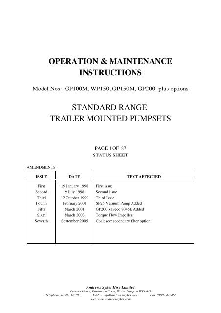
OPERATION & MAINTENANCEINSTRUCTIONSModel Nos: <strong>GP</strong><strong>100M</strong>, WP150, <strong>GP</strong>150M, <strong>GP</strong>200 -plus optionsSTANDARD RANGETRAILER MOUNTED PUMPSETSPAGE 1 OF 87STATUS SHEETAMENDMENTSISSUE DATE TEXT AFFECTEDFirstSecondThirdFourthFifthSixthSeventh19 January 19989 July 199812 October 1999February 2001March 2001March 2003September 2005First issueSecond issueThird IssueSP25 Vacuum Pump Added<strong>GP</strong>200 x Iveco 8045E AddedTorque Flow ImpellersCoalescer secondary filter option.<strong>Andrews</strong> <strong>Sykes</strong> Hire LimitedPremier House, Darlington Street, Wolverhampton WV1 4JJTelephone: 01902 328700 E-Mail:info@andrews-sykes.com Fax: 01902 422466web:www.andrews-sykes.com
<strong>Sykes</strong> PumpsRef.No.SY381-4Issue Status: seventhOPERATION& MAINTENANCE INSTRUCTIONS Page 2 of 87STANDARD RANGE TRAILER MOUNTED PUMPSIssued : 9 July1 CONTENTS1 CONTENTS 21.1 List of Illustrations 41.2 List of Tables 52 FOREWORD 63 SERVICING AND REPAIR INFORMATION 73.1 Contacting your local <strong>Sykes</strong> depot 73.2 Ordering spares 74 SAFETY PRECAUTIONS 84.1 Warnings and Cautions 84.2 Training 85 DESCRIPTION OF EQUIPMENT 95.1 General description 95.2 Technical description 95.2.1 Overview 95.2.2 Main pump 115.2.3 Vacuum Pump 125.2.4 Engine, drives and fuel system 135.2.5 145.2.6 Chassis 155.3 Product Identification 166 HANDLING AND OPERATION 176.1 Lifting and transportation 176.2 Care and storage 176.3 Trailer routine checks 176.4 Siting and preparation for pumping 176.5 Controls and connection points 186.5.1 Main control panel 186.6 Operating instructions 196.6.1 General precautions 196.6.2 Starting up 196.6.3 Shutting down 206.7 Testing 216.7.1 Pump performance fault diagnosis 226.7.2 Priming system fault diagnosis 23
<strong>Sykes</strong> PumpsRef.No.SY381-4Issue Status: seventhOPERATION& MAINTENANCE INSTRUCTIONS Page 3 of 87STANDARD RANGE TRAILER MOUNTED PUMPSIssued : 9 July7 MAINTENANCE 247.1 Tools required 247.2 Maintenance schedule 247.3 General instructions and precautions 267.4 Engine and fuel system 267.4.1 General 267.4.2 Cleaning the fuel tank 267.5 Vacuum pump drive belt 277.5.1 Adjusting belt tension 277.5.2 Renewing the belt 287.6 Coalescer oil feed and filters 287.7 Coalescer 287.8 Priming tank air filter, surge control valve and air valve 297.9 Vacuum pump 317.9.1 Removing the vacuum pump 317.9.2 Dismantling the vacuum pump 327.9.3 Reassembling the vacuum pump 337.9.4 Refitting vacuum pump 347.10 Non-return valve 357.11 Greasing the main pump bearings 357.12 Main pump impeller and wear plates 357.13 Main pump pressure seal 367.13.1 Removing and refitting pump pressure seal 367.13.2 Renewing the pump pressure seal packing 367.14 Dismantling the drive 377.14.1 Tyre coupling 377.14.2 Flywheel coupling installation 387.15 Main pump shaft and bearings 397.15.1 Dismantling the shaft and bearings 407.15.2 Renewing/re-fitting the bearings 407.15.3 Fitting the bearing frame 407.15.4 Fitting the impeller and setting wear plate clearances 418 SPARE PARTS 428.1 Introduction 428.2 Ordering Spares 429 APPENDICES 869.1 Associated Publications 86
<strong>Sykes</strong> PumpsRef.No.SY381-4Issue Status: seventhOPERATION& MAINTENANCE INSTRUCTIONS Page 4 of 87STANDARD RANGE TRAILER MOUNTED PUMPSIssued : 9 July1.1 List of IllustrationsFigure 1 Schematic of flow around the pumpset 10Figure 2 Main panel for electric start Lister TR engines, only 18Figure 3 Pump fault diagnosis flowchart 22Figure 4 Priming fault diagnosis chart 23Figure 5 Vacuum pump pulley arrangement 27Figure 6 Belt alignement 28Figure 7 Coalescer filter removal 29Figure 8 Vacuum priming tank 30Figure 9 Priming tank air and surge control valves 31Figure 10 - Taper Lock® screw positions 32Figure 11 - vacuum pump rotor 32Figure 12 Non-return valve 35Figure 13 Tyre coupling assembly 37Figure 14 Flywheel coupling 38Figure 15 213W (element size) only 39Figure 16 Shaft alignment 39Figure 17 G.A. of two wheel site trailer 45Figure 18 G.A. of 4-Wheel Site Trailer 48Figure 19 <strong>GP</strong>200 Only 48Figure 20 G.A. 2-Wheel High Speed Trailer 51Figure 21 Bearing/Shaft Assembly - WP150 & <strong>GP</strong><strong>100M</strong> 53Figure 22 Bearing/Shaft Assembly - <strong>GP</strong>150M & <strong>GP</strong>200 55Figure 23 Pressure Seal Assembly 57Figure 24 Impeller/Wear Plate Assembly - WP150 & <strong>GP</strong><strong>100M</strong> 59Figure 25 Impeller/Wear Plate Assembly - <strong>GP</strong>150M & <strong>GP</strong>200 61Figure 26 Non Return Valve Assembly 63Figure 27 - Vacuum Pump - Drives and Fittings 65Figure 28 FL 25cfm Vacuum Priming System 67Figure 29 SP25 cfm Vacuum Priming System 67Figure 30 FL60 Vacuum Priming Pump 69Figure 31 SP60 Vacuum Priming Pump 69Figure 32 25cfm Priming Tank Assembly 71Figure 33 60 cfm priming tank 73Figure 34 Coalescer spare parts 75Figure 35 Two wheel site trailer 77Figure 36 Four wheel site trailer 79Figure 37 Two wheel high speed trailer 81Figure 38 10/25 CFM Sump/Tee piece & Fittings Assembly 83Figure 39 60 CFM Sump/Tee piece & Fittings Assembly 83Figure 40 Large volume sump-tee 85
<strong>Sykes</strong> PumpsRef.No.SY381-4Issue Status: seventhOPERATION& MAINTENANCE INSTRUCTIONS Page 5 of 87STANDARD RANGE TRAILER MOUNTED PUMPSIssued : 9 July1.2 List of TablesTable 1 Main pump technical data 11Table 2 Vacuum system technical data 12Table 3 Engine and fuel system technical data 13Table 4 Approximate component and combined weights 14Table 5 Chassis technical data 15Table 6 Vacuum pump clearance and dimensions 33Table 7 Clamping Screw Coupling Torque and Flange Spacing 'M 37Table 8 Coupling gap setting 37Table 9 - Flywheel settings39Table 10 Impeller clearances 41
<strong>Sykes</strong> PumpsRef.No.SY381-4Issue Status: seventhOPERATION& MAINTENANCE INSTRUCTIONS Page 6 of 87STANDARD RANGE TRAILER MOUNTED PUMPSIssued : 9 July2 FOREWORDThis manual covers the <strong>Andrews</strong> <strong>Sykes</strong> STANDARD RANGE TRAILER-MOUNTED PUMPSETS.It is written for operators and maintenance personnel and provides the information needed for safe andefficient siting, use, testing, routine maintenance and repairs.Manuals provided are an essential part of the relevant equipment. They should be kept for the life ofthe equipment and passed on to any subsequent purchaser. Any amendment issued by <strong>Andrews</strong> <strong>Sykes</strong>Hire Limited should be promptly incorporated into this manual.Information contained in this manual is correct at the date of publication. As improvements arecontinually being made, <strong>Andrews</strong> <strong>Sykes</strong> Hire Limited reserve the right to make alterations withoutgiving prior notice.© 1998 <strong>Andrews</strong> <strong>Sykes</strong> Hire Limited. The contents of this manual are copyright and must not bereproduced without prior permission of <strong>Andrews</strong> <strong>Sykes</strong> Hire Limited.Product names referenced in this manual are registered trade marks of the original equipmentmanufacturers.HEALTH & SAFETY STATEMENTDO TAKE TIME TO ENSURE THAT YOUR SAFETY AND THAT OF OTHERS IS NOT PUT AT RISK. FAILURE TOOBSERVE PRECAUTIONS, BOTH ELEMENTARY AND THOSE EXPLICIT IN THIS MANUAL, MAY RESULT INPERSONAL INJURY AND/OR DAMAGE TO EQUIPMENT. THE SAFETY INFORMATION ON PAGE 8 ISINTENDED TO MAKE YOU AWARE OF HAZARDS AND PRECAUTIONS AND TO ENCOURAGE A SAFETY-CONSCIOUS APPROACH TO OPERATING AND CARRYING OUT MAINTENANCE WORK ON THIS EQUIPMENT.
A new, updated version of the Monthly EconomicDevelopment Report has been posted tothe City’s website to keep you up-to-date and informedon what’s happening in your City.This report contains information pertaining toLaconia’s unemployment rate and wages, as wellas business and economic development partnerships.We hope you find this reporthelpful and informative!Contact the City Mgr’s office at527-1270, orinfo@city.laconia.nh.usCity of Laconia Job Openings!Following are current job opportunitieswith the City of Laconia:Firefighter/EMT - Paramedic:Job Posting / Job DescriptionNow is the time to file for NH State Low and ModerateIncome Homeowners Property Tax Relief! Form DP-8must be filed no later than June 30, 2012. The Stateno longer mails the forms to property taxpayers whohave filed in prior years.You are eligible to file for this tax relief if:• You own a homestead subject to the stateeducation property tax;• You have resided in such homestead on April 1of the year for which the claim for relief is made;• You have a total adjusted gross householdincome of $20,000 or less if a single person,or $40,000 or less if married or head of a NHhousehold.Be sure to attach a copy of your final 2011 propertytax bill and your 2011 federal tax return for eachclaimant and all adult members of the claimant’shousehold for the corresponding period.DP-8 forms can be obtained online by clicking here orby calling 603-230-5000. Completed forms are sentto: NH Dept of Revenue Administration, DocumentProcessing Division, PO Box 299, Concord, NH 03302-0299.Click for Assessing Dept.We hope you have enjoyed thisEdition ofWe welcome your input, commentsand suggestions!Feel free to contact us at theCity Manager’s office, 527-1270,or by e-mail at info@city.laconia.nh.usHave a great weekend!Scott Myers, City ManagerCity of LaconiaCity’s Website: www.city.laconia.nh.usCity Hall will be closed onMonday, May 28, 2012We apologize for anyinconvenience!A complete list of 2012 CityHall closings can be accessedon our websiteby clicking here.
<strong>Sykes</strong> PumpsRef.No.SY381-4Issue Status: seventhOPERATION& MAINTENANCE INSTRUCTIONS Page 8 of 87STANDARD RANGE TRAILER MOUNTED PUMPSIssued : 9 July4 SAFETY PRECAUTIONS4.1 Warnings and CautionsFor the purpose of definition in this manual, a WARNING gives information which, if ignored, couldengender serious injury to personnel. A CAUTION gives information which if ignored could causeserious damage to the machine or associated equipment.WARNINGWarning notices are boxed and highlighted in the style of this paragraph.CAUTIONCautionary notices are boxed and highlighted in the style of this paragraph.4.2 TrainingIt is strongly recommended that all operators, other personnel working on or near the pump, and anysite visitors, are made fully aware of the potential dangers of this rotating equipment. If in ANY doubtplease contact <strong>Andrews</strong> <strong>Sykes</strong> Limited Hire for advice.WARNINGSFOR YOUR OWN PERSONAL SAFETY READ AND TAKE NOTE OF THE FOLLOWING:Hazardous areas - All moving parts, including drive belts, are dangerous. Allsuch moving parts are individually guarded and the pumpsetMUST have all guarding in place during operation.Pump intake and discharge ports are also dangerous whenopen. Do not insert hands or other objects into the portswhen the pump is operating.Lifting and transport - Read and follow the instructions on page 17. In particular,always lift using the lifting points provided and ensure thatany lifting equipment is of adequate load-carrying capacityand possesses a valid test certificate.Operating the pump - Note the general precautions on page 18 and ensure that youare familiar with the controls before operating the pump.Read and follow the instructions on safe siting andoperation on pages 17 to 21.Fault finding and pumpmaintenance- Follow a regular maintenance schedule as defined on page24.
<strong>Sykes</strong> PumpsRef.No.SY381-4Issue Status: seventhOPERATION& MAINTENANCE INSTRUCTIONS Page 9 of 87STANDARD RANGE TRAILER MOUNTED PUMPSIssued : 9 July5 DESCRIPTION OF EQUIPMENT5.1 General descriptionThe <strong>GP</strong> is a range of general purpose, self priming, free standing site pumps. The pumps can be usedin a range of environmental conditions, including tropical temperatures.Each pump is capable of passing solids up to the specified maximum diameter for the size of machine(see Table 1, page 11), provided the solids are in suspension; a typical example being ditch watercontaining soil and rock particles. Slurries may also be pumped, if concentration of solid matter isnot too high. The pumps can also handle abrasive materials at the expense of higher wear rate. (Foradvice on the suitability of your pump for specific applications contact your local <strong>Sykes</strong> depot; seeSection 3.1, page 7.)<strong>GP</strong> pumps are normally powered by a diesel engine with electric start. They are supplied on a fourwheeled site trailer, two wheeled site trailer or two wheeled high speed road trailer chassis.See CE certificate for applicable noise levels during operation.5.2 Technical description5.2.1 OverviewThis section identifies the main components of the standard pump and provides general technical andperformance data. It does not cover any special options or modifications made to suit customerrequirements.L NOTE: Tolerances are given in Maintenance, Section 7 page 24.LNOTE: By adjusting the ‘surge control valve’, when the pump is fully primed, the operator canprevent continual air valve cycling -an effect referred to as ‘snoring’ (See Figure 8 andFigure 9).Figure 1 illustrates, schematically, the pumpset's principle of operation.
<strong>Sykes</strong> PumpsRef.No.SY381-4Issue Status: seventhOPERATION& MAINTENANCE INSTRUCTIONS Page 10 of 87STANDARD RANGE TRAILER MOUNTED PUMPSIssued : 9 JulyPRIMING PUMPCOALESCEREXHAUST TOATMOSPHEREFILTERED AIRINTAKE FROMATMOSPHEREAIR FILTERFILTERMAIN DISCHARGESURGECONTROLVALVEDRAIN PLUGDRIVENON RETURNVALVEDRIVEPRIMINGTANKMAIN PUMPENGINESOURCEMAIN FLOWVACUUMFLOWVACUUM DRAWN LUBRICATING OILEXHAUSTFLOWFigure 1 Schematic of flow around the pumpset
<strong>Sykes</strong> PumpsRef.No.SY381-4Issue Status: seventhOPERATION& MAINTENANCE INSTRUCTIONS Page 11 of 87STANDARD RANGE TRAILER MOUNTED PUMPSIssued : 9 July5.2.2 Main pumpFigure 21 to Figure 25 show the main pump in detail.Table 1 Main pump technical dataPARAMETER <strong>GP</strong><strong>100M</strong> WP150 <strong>GP</strong>150M <strong>GP</strong>200Standard pump body(volute) materialCast iron Cast iron Cast iron Cast ironVolute size 100mm 100mm 150mm 150mmIntake and dischargeports100mmBSTDflange150mmBSTDflange150mmBSTDflange200 BSTDflangeSolids handlingcapability (maximumdiameter)Maximum lift(theoretical)Maximum dischargehead44mm 50mm 52mm 48mm10m 10m 10m 10m32m 38m 42m 65mMaximum flow 160m³/hr 210m³/hr 320m³/hr 430m³/hrPump bearing greaseShellAlvaniaEP2 orequivalentShellAlvaniaEP2 orequivalentShellAlvania EP2orequivalentShellAlvania EP2or equivalentNominal speed 1800 rpm 1800 rpm 1800 rpm 1800 rpm
<strong>Sykes</strong> PumpsRef.No.SY381-4Issue Status: seventhOPERATION& MAINTENANCE INSTRUCTIONS Page 12 of 87STANDARD RANGE TRAILER MOUNTED PUMPSIssued : 9 July5.2.3 Vacuum PumpFigures 30 to 33 show exploded views of the vacuum pumps. Figure 29 shows it assembled ontothe pump set.Table 2 Vacuum system technical dataCOMPONENT/PARAMETERVacuum pumpdisplacement25cfm12 litres/s 28 litres/s60cfmVacuum level 9m 9mLubricating oil30 SAE viscosity below30ºC10W30 SAE above 30ºC30 SAE viscosity below 30ºC10W30 SAE above 30ºCNominal speed 1550 rpm 1100 rpm
<strong>Sykes</strong> PumpsRef.No.SY381-4Issue Status: seventhOPERATION& MAINTENANCE INSTRUCTIONS Page 13 of 87STANDARD RANGE TRAILER MOUNTED PUMPSIssued : 9 July5.2.4 Engine, drives and fuel systemTable 3 Engine and fuel system technical dataCOMPONENT/PARAMETEREngineCOMMENTSDrives mainand vacuumpumpsSPECIFICATION<strong>GP</strong><strong>100M</strong> WP150 <strong>GP</strong>150M <strong>GP</strong>200MListerTR2 aircooleddieselListerTS3 aircooleddieselListerTR3 aircooleddieselIveco8045SETurbodieselMain pumpcouplingHighmisalignmenttolerance andvibrationisolationFennaflextyrecouplingFennaflextyrecouplingFennaflextyrecouplingFennerflywheelcouplingVacuum pumptransmissionFennertootheddrive beltandpulleysFennertootheddrive beltandpulleysFennertootheddrive beltandpulleysFennertootheddrive beltandpulleysBattery 12V 669540 Ah12V 669540 Ah12V 669540 Ah12V 643103 AhFuel tank 110 litres 110 litres 110 litres 150 litresApproximaterunning time onfull tank, at maxload29 hours 22 hrs 20 hrs 11 hrsNominal speed 1800 rpm 1800 rpm 1800 rpm 1800 rpm
<strong>Sykes</strong> PumpsRef.No.SY381-4Issue Status: seventhOPERATION& MAINTENANCE INSTRUCTIONS Page 14 of 87STANDARD RANGE TRAILER MOUNTED PUMPSIssued : 9 July5.2.5 WeightsTable 4 provides apppoximate component weights for the pumpset and its major components. Theweights given are typical and may vary by ±20% for individual machines. Therefore, ensure that alllifting and towing equipment used have a safe working load of at least 120% of the relevant indicatedweight.Table 4 Approximate component and combined weightsCOMPONENTWEIGHT (kg)<strong>GP</strong><strong>100M</strong> WP150 <strong>GP</strong>150M <strong>GP</strong>200MEngine 245 260 260 400Main pump 300 450 525 605Main pump, priming tank,engine and coupling600 775 850 1065Priming tank 30 45 45 45Gross weight inc. chassis &full tank of fuel for 4-wheelsite trailerGross weight inc. chassis &full tank of fuel for 2-wheelsite trailerGross weight inc. chassis &full tank of fuel for 2-wheelhigh speed trailer1000 1175 1250 1605950 1125 1200 —1200 1375 1450 ----
<strong>Sykes</strong> PumpsRef.No.SY381-4Issue Status: seventhOPERATION& MAINTENANCE INSTRUCTIONS Page 15 of 87STANDARD RANGE TRAILER MOUNTED PUMPSIssued : 9 July5.2.6 ChassisTable 5 Chassis technical dataCOMPONENT/PARAMETERGeneralspecification2-wheel site trailer 4-wheel site trailer 2-wheel high speedtrailerFixed towing armRear fixed, frontswivel armBeam axle suspension,A-frame fixed chassisMaximum towingspeedSite limits apply(10-15 mph)Site limits apply(10-15 mph)Legal speed limitTyres Pneumatic Solid Pneumatic road tyresTow-hitch detailsTowing eye to suitvertical towing pin(max 50mm)Towing eye to suitvertical towing pin(max 50mm)50 mm dia. ball hitch,brakedRecommendedlifting methodsCrane, using thesingle lifting point.Crane, using thesingle lifting point.Crane, using the singlelifting point.
<strong>Sykes</strong> PumpsRef.No.SY381-4Issue Status: seventhOPERATION& MAINTENANCE INSTRUCTIONS Page 16 of 87STANDARD RANGE TRAILER MOUNTED PUMPSIssued : 9 July5.3 Product IdentificationFor your own security and to enable <strong>Andrews</strong> <strong>Sykes</strong> Hire Limited to answer any enquiries and requestsfor service and spares, where not stated, record details of your pumpset in the table below.DETAILCORRESPONDING INFORMATION<strong>GP</strong><strong>100M</strong>WP150Chassis Type 4WST 2HST 2WST 4WSTSerial Number SY3811051 SY3811052 SY3821084 SY3821078Serial Number SuffixSerial Number SY3821084-2 SY3821079Serial Number SuffixVariations From Standard Hand-start Engine Large Volume SumpTeeSerial NumberSerial Number SuffixVariations From StandardEngin Serial NumberDate of PurchaseDETAILCORRESPONDING INFORMATION<strong>GP</strong>150M<strong>GP</strong>200Chassis Type 2WST 4WST 2HST 4WST 2HSTSerial Number SY3831075 SY3831067 SY3831068 SY3841036 SY3841069Serial Number SuffixSerial Number SY3831070 SY3831068-R SY3841033Serial Number SuffixVariations From StandardLarge VolumeSump TeeAnti-RaggingImpeller & FrontWear Plate25 cfm VacuumDrive AssemblySerial Number SY3831065 SY3831069Serial Number SuffixVariations From StandardEngin Serial NumberDate of Purchase25 cfm VacuumDrive Assembly25 cfm VacuumDrive Assembly
<strong>Sykes</strong> PumpsRef.No.SY381-4Issue Status: seventhOPERATION& MAINTENANCE INSTRUCTIONS Page 17 of 87STANDARD RANGE TRAILER MOUNTED PUMPSIssued : 9 July6 HANDLING AND OPERATION6.1 Lifting and transportationAll pumpset variants are equipped with the single point lifting eye by which they may be lifted usinga suitable chain.WARNINGSDO NOT attempt to lift pump with suction and discharge hoses in place.ALWAYS ensure that lifting gear are adequate for the weight being lifted (See Table 4.).The trailer may be towed behind a suitable vehicle. Check that the vehicle has a suitable towbar.6.2 Care and storageTo maintain the body parts in good condition, it is strongly recommended that the trailer is steam orspray cleaned regularly to remove road dirt, mud and grit.See Section 6.6.3 for shutting down procedure.When not in use store the trailer under cover in a dry environment, where practicable.6.3 Trailer routine checksRoutine checks are essential for personal safety and maintenance of equipment condition. (ConsultTable 5 for all chassis related technical data.)6.4 Siting and preparation for pumpingIf you wish to test pump operation before use, refer to Testing, page 21.6.4.0.1 Place the pumpset on a firm, level area of ground, as close as practical to the source of liquid.6.4.0.2 Connect the hoses to the intake and discharge flanges.LNOTE: USE all the bolt holes provided on the flanges. DO NOT use a collapsible hose on the suctionside, and make sure the strainer is in place on the suction side.6.4.0.3 Submerge the end of the suction hose.6.4.0.4 Place the end of the discharge hose in a suitable outlet.
<strong>Sykes</strong> PumpsRef.No.SY381-4Issue Status: seventhOPERATION& MAINTENANCE INSTRUCTIONS Page 18 of 87STANDARD RANGE TRAILER MOUNTED PUMPSIssued : 9 JulyCAUTIONDO NOT put any stress on hoses. Lay them so as to avoid forming sharp kinks and protect themwhere they come in contact with abrasive surfaces.6.5 Controls and connection points6.5.1 Main control panelOFFRUN PRE HEATSTARTStarting SwitchRunning Hours½0 0 0 0 0 0 hFigure 2 Main panel for electric start Lister TR engines, only
<strong>Sykes</strong> PumpsRef.No.SY381-4Issue Status: seventhOPERATION& MAINTENANCE INSTRUCTIONS Page 19 of 87STANDARD RANGE TRAILER MOUNTED PUMPSIssued : 9 July6.6 Operating instructions6.6.1 General precautionsWARNINGSDO NOT attempt to insert anything into the pump intake and discharge ports while the engine isrunning.Ensure the pumpset is stable and immobilised BEFORE starting the pump.WARNINGSBEWARE of fire risks. DO NOT place any flammable material near or around the engine orexhaust. Allow adequate ventilation.The engine, exhaust and coalescer become HOT during operation.ENSURE that any discharge into rivers or watercourses, or to soak away onto land, isenvironmentally acceptable.The pump body retains liquid which could be hazardous to health. Flush the pump withclean water BEFORE disconnecting the hoses or working on the pump.LNOTE: In the event of an emergency, STOP the engine IMMEDIATELY using the engine keyon the main control pane .NEVER use the pump without a strainer.CAUTIONSDO NOT pump, either liquids that may damage the pump, or dry material. If in doubtcontact your local <strong>Andrews</strong> <strong>Sykes</strong> depot for advice (see Section 3.1, page 7).6.6.2 Starting upFollow this procedure before each engine start-up. Refer to Section 6.5, page 18, for detailsof controls.WARNINGSMake sure you are familiar with the engine manufacturer’s safety instructions BEFORErunning the engine.
<strong>Sykes</strong> PumpsRef.No.SY381-4Issue Status: seventhOPERATION& MAINTENANCE INSTRUCTIONS Page 20 of 87STANDARD RANGE TRAILER MOUNTED PUMPSIssued : 9 JulyCAUTIONALWAYS top up using oil of correct specification. See the manufacturer’s handbook for detailsof engine oil, and Table 2, page 12, for details of vacuum pump oil.6.6.2.1 Drain any water in the coalescer through the drain tap provided.6.6.2.2 Check and top up, if necessary;6.6.2.2.0.1 the engine fuel, oil and radiator water levels;6.6.2.2.0.2 the oil level in the coalescer.LNOTE: Oil surface should be just visible when looking into the filler strainer.6.6.2.3 Ensure that all drain taps are closed.6.6.2.4 Screw in fully the priming tank surge control valve, to allow the system to prime.6.6.2.5 Submerge the suction hose in the source.6.6.2.6 Refer to Figure 2. Turn the ignition key to ON position.6.6.2.7 Turn the key to WARM UP position for 15 seconds.6.6.2.8 Turn the key clockwise to the START position and release as soon as the engine starts.If the engine fails to start within 30 seconds, release the key and attempt to restart afterallowing time for all moving parts to come to rest.(The pump should prime automatically. In case of start-up failure, consult Fault diagnosis onpage 23.)6.6.2.9 When the pump is fully primed, re-adjust the surge control valve, as necessary, to avoid'snoring' -see page 9.6.6.3 Shutting downL NOTE: TO STOP- Turn the engine key to the STOP position and push in fully the surgecontrol valve knob to release the vacuum and empty the the primingtank and the intake hose.
<strong>Sykes</strong> PumpsRef.No.SY381-4Issue Status: seventhOPERATION& MAINTENANCE INSTRUCTIONS Page 21 of 87STANDARD RANGE TRAILER MOUNTED PUMPSIssued : 9 JulyCAUTIONALWAYS drain the pump; before removing it, or if it is being left unused for a while -especially in cold weather.The procedure is as stated below.6.6.3.1 Flush the pump with clean water.6.6.3.2 Drain water from the following, through the drain taps or plugs provided;6.6.3.2.0.1 the main pump;6.6.3.2.0.2 the priming tank; and,6.6.3.2.0.3 the non-return valve.6.6.3.2.0.4 the coalescer6.6.3.3 Follow the engine manufacturer's instructions relating to engine being left unused fora period of time.If the pump is to be moved to a new site, disconnect the hoses and follow the instructions inSection 6.1, Lifting and transportation, page 17.CAUTIONNEVER leave water in the pumps or hoses if there is any risk of it freezing.6.7 TestingTo test correct operation of the pumpset before its first service, or whenever required, followthe procedure described below.6.7.0.1 Immobilise and secure the pumpset, at the test site.6.7.0.2 Start the engine as described in Section 6.6.2, page 19, but leave the surge control valvefully screwed in throughout the test.6.7.0.3 Place a 'cone tester' (or an alternative test gauge) in the inlet flange and check that thevacuum reading is sufficient for the intended lift plus the pipework losses. If thevacuum reading is unsatisfactory or the pump fails to prime consult fault diagnosis,Section 6.7.2, page 23.6.7.0.4 Stop the engine.
<strong>Sykes</strong> PumpsRef.No.SY381-4Issue Status: seventhOPERATION& MAINTENANCE INSTRUCTIONS Page 22 of 87STANDARD RANGE TRAILER MOUNTED PUMPSIssued : 9 July6.7.1 Pump performance fault DiagnosisPOOR PUMP PERFORMANCEWhen coupled to short discharge pipei) Is strainer blocked ?ii) Has suction hose collapsed ?iii) Are suction hose seals missing ?When pumping a greatdistance or headIs enginespeed low ?Take pump vacuum readingCheck the discharge lineIs it lowcompared with suction liftof application ?Adjust or rectify asapropriatei) Is it too long ?ii) Has it too many bends ?iii) Does it rise a great height ?iv) A combination of the above ?v) Has it collapsed or crushed ?Isengine speed low ?Does thepump dischargeinto a pipeline underpressure ?Isnon-return valveblocked ?Verify that pump is suitable foryour application. Consult yourlocal Andrew <strong>Sykes</strong> depot.STOP engineIs thepump suitable ?See 'Pump Failsto Prime' flow chartIs impellerblocked, heavilyworn or do wear platesneed adjusting ?STOP engineContact your nearest Andrew <strong>Sykes</strong> Depot for adviceFigure 3 Pump fault diagnosis flowchart
<strong>Sykes</strong> PumpsRef.No.SY381-4Issue Status: seventhOPERATION& MAINTENANCE INSTRUCTIONS Page 23 of 87STANDARD RANGE TRAILER MOUNTED PUMPSIssued : 9 July6.7.2 Priming system fault diagnosisFigure 4 Priming fault diagnosis chart
<strong>Sykes</strong> PumpsRef.No.SY381-4Issue Status: seventhOPERATION& MAINTENANCE INSTRUCTIONS Page 24 of 87STANDARD RANGE TRAILER MOUNTED PUMPSIssued : 9 July7 MAINTENANCE7.1 Tools required7.1.0.1 A standard fitters-toolkit.7.2 Maintenance scheduleThe following schedule provides a guide for maintaining the pump. The actual hours ofoperation between maintenance will depend on the operating conditions. For full details ofengine maintenance, refer to the manufacturer’s handbook.Maintenance descriptionRefertoSectionRunning hoursDaily 125 250 500 2000 6000Vacuum pump and priming system:Drain water from coalescer 5.3 ×Check coalescer oil level andtop up if requiredCheck tension and conditionof vacuum pump drive beltChange vacuum pump oil andclean oil filtersCheck priming tank valvesand clean or renew air filterRenew vacuum pump drivebeltCheck non-return valve ball issealing on seatDismantle and clean primingtank, valves and pipesCheck performance ofvacuum pump and overhaulas necessary5.3 ×7.5 ×7.6 ×7.8 ×7.5 ×7.10 ×7.8 ×7.9 ×
<strong>Sykes</strong> PumpsRef.No.SY381-4Issue Status: seventhOPERATION& MAINTENANCE INSTRUCTIONS Page 25 of 87STANDARD RANGE TRAILER MOUNTED PUMPSIssued : 9 JulyMaintenance descriptionRefertoSectionRunning hoursDaily 125 250 500 2000 6000Clean coalescer filter 7.6 ×Main pump:Grease pump bearings 7.11 × ×Check impeller and wearplates for wear and renew oradjust as required.Renew pump pressure sealgland packingCheck condition of mainpump bearings7.12 ×7.13 ×7.15 ×
<strong>Sykes</strong> PumpsRef.No.SY381-4Issue Status: seventhOPERATION& MAINTENANCE INSTRUCTIONS Page 26 of 87STANDARD RANGE TRAILER MOUNTED PUMPSIssued : 9 July7.3 General instructions and precautionsWARNINGSALWAYS ensure that slings, shackles etc. are adequate for the weight being lifted. (See Table4, page 14.)Chock and stabilise the chassis BEFORE commencing work.Drain main pump volute and priming tank.CAUTIONSALWAYS remove major component to clean workshop conditions for overhaul.7.3.0.1 Disconnect the wiring loom from the control panel.7.3.0.2 Disconnect and remove the battery.7.3.0.3 Disconnect the fuel hoses and from the engine.7.3.0.4 Remove all guarding.7.3.0.5 Disconnect the engine from its mounts and the pump bearing frame.7.3.0.6 Disconnect the drive coupling.7.3.0.7 Lift engine by its lifting points (Lifting gear will be required).7.3.0.8 Disconnect the pump from its mounts.7.3.0.9 Using suitable lifting straps, remove pump end assembly.7.4 Engine and fuel system7.4.1 GeneralConsult original manufacturer’s handbook for engine maintenance instructions.7.4.2 Cleaning the fuel tank7.4.2.1 Remove the drain plugs and drain the fuel tank. See Figure 35 to Figure 37.7.4.2.2 Remove all traces of dirt, debris and fuel by steam cleaning.7.4.2.3 Drain the tank of all water and ensure that its inside is dry.7.4.2.4 Replace the drain plug.
<strong>Sykes</strong> PumpsRef.No.SY381-4Issue Status: seventhOPERATION& MAINTENANCE INSTRUCTIONS Page 27 of 87STANDARD RANGE TRAILER MOUNTED PUMPSIssued : 9 July7.5 Vacuum pump drive beltThe vacuum pump pulley arrangement is illustrated below in Figure 5.Figure 5 Vacuum pump pulley arrangement7.5.1 Adjusting belt tension7.5.1.1 Remove vacuum drive guard.7.5.1.2 Loosen the vacuum pump mounting holding down nuts.7.5.1.3 Reposition the vacuum pump to adjust the tension of th belt. (At the correct tension aforce of 2.5kg is needed to deflect the belt 10-13mm at the midpoint between thepulleys.)7.5.1.4 When the vacuum pump is in the correct position, tighten the vacuum pump holdingdown nuts.7.5.1.5 Using a straight edge, ensure that the priming pump and main pump pulleys are alignedso that parallel misalignment is less than 5mm per metre between pulley centres, andangular misalignment does not exceed ¼° (refer to Figure 6). Correct the alignmentif necessary.7.5.1.6 Replace the priming pump drive guard.
<strong>Sykes</strong> PumpsRef.No.SY381-4Issue Status: seventhOPERATION& MAINTENANCE INSTRUCTIONS Page 28 of 87STANDARD RANGE TRAILER MOUNTED PUMPSIssued : 9 JulyFigure 6 Belt alignement7.5.2 Renewing the belt7.5.2.1 Remove vacuum drive guard.7.5.2.2 Loosen the vacuum pump holding down nuts and slacken the belt.7.5.2.3 Disassemble the drive coupling (referring to the manufacturer’s operation andmaintenance instructions for the type of coupling used).7.5.2.4 Remove the timing belt from its pulleys, fit a new belt and adjust the tension asdescribed in Section 7.5.1 (ensuring correct teeth/pulley seating).7.5.2.5 Reassemble the drive coupling as per manufacturer’s instructions.7.5.2.6 Replace all guarding.7.6 Coalescer oil feed and filters7.7 CoalescerCheck the coalescer oil level daily. This should be level with the neck of the filler cap. Drainany water present in the coalescer by using the drain cock provided. If excessive water isfound or the oil appears dirty, the oil and coalescent filters should be inspected. Clean thesefilters if they prove to be contaminated.
<strong>Sykes</strong> PumpsRef.No.SY381-4Issue Status: seventhOPERATION& MAINTENANCE INSTRUCTIONS Page 29 of 87STANDARD RANGE TRAILER MOUNTED PUMPSIssued : 9 JulyOther maintenance of the coalescer is limited to regular cleaning of the oil and coalescentfilters. The oil filter is located in the oil feed connection to the vacuum priming pump. Thecoalescent filter is situated underneath the coalescer lid.lid securing screwscoalescent filteroil filterdrain cockFigure 7 Coalescer filter removal7.7.0.1 Drain the oil from the coalescer by unscrewing the drain cock.7.7.0.2 Remove the four screws (shown as ‘%’ in Figure 7, page 29).7.7.0.3 Remove the lid and the filter retainer.7.7.0.4 Lift out the coalescent filter.7.7.0.5 Detach the vacuum pump oil feed pipe and unscrew the oil supply connection on thecoalescer.7.7.0.6 Remove the oil filter.7.7.0.7 Clean the coalescent and oil filters with a suitable solvent and fully dry both filters.7.7.0.8 Reassembly is a straightforward reversal of disassembly. Cleaning or renewing thecoalescer mesh.
<strong>Sykes</strong> PumpsRef.No.SY381-4Issue Status: seventhOPERATION& MAINTENANCE INSTRUCTIONS Page 30 of 87STANDARD RANGE TRAILER MOUNTED PUMPSIssued : 9 July7.8 Priming tank air filter, surge control valve and air valvetop coverfloatprimarychambervalve coversurge controlvalve assemblymain valveelement airfilterball valvepriming tanksecondary chamberair outletSecondary chamberdrain assemblyFigure 8 Vacuum priming tank
<strong>Sykes</strong> PumpsRef.No.SY381-4Issue Status: seventhOPERATION& MAINTENANCE INSTRUCTIONS Page 31 of 87STANDARD RANGE TRAILER MOUNTED PUMPSIssued : 9 JulyFigure 9 shows the air and surge control valve assemblies , indicating areas that should be checkedfor wear and damage. To access the valves or for cleaning out, remove the priming tank top completewith valve gear. Renew parts, as necessary and grease valve seats to prevent seizure.Regularly checkfor wear areasindicated.Air valveSurge control valveFigure 9 Priming tank air and surge control valves7.9 Vacuum pump7.9.1 Removing the vacuum pumpSee ? on page 65.WARNINGLifting equipment IS required to remove the 60 ft 3 /min vacuum pump, where fitted. Check TechnicalSpecification, section 5.2.7.9.1.1 Remove vacuum drive guard.7.9.1.2 Disconnect hoses from the vacuum pump.7.9.1.3 Using a suitable spanner, disconnect the oil feed pipe at the vacuum pump and withdraw theoil feed pipe.7.9.1.4 Loosen the vacuum pump holding down nuts.7.9.1.5 Remove the timing belt.7.9.1.6 Remove the vacuum pump and pulley.
<strong>Sykes</strong> PumpsRef.No.SY381-4Issue Status: seventhOPERATION& MAINTENANCE INSTRUCTIONS Page 32 of 87STANDARD RANGE TRAILER MOUNTED PUMPSIssued : 9 July7.9.2 Dismantling the vacuum pumpCAUTIONDismantling the pump should be done in clean workshop conditions. Have swabs available to soakup any oil remaining in the pump.refer to ? and Figure 307.9.2.1 Remove the priming pump pulley, complete with Taper Lock® bush as follows:7.9.2.1.1 Slacken, by several turns, all screws in the TaperLock® bush. Remove one or two, according tothe number of jacking holes (shown as ‘!’ inFigure 10).7.9.2.1.2 Oil the thread of each screw, the point of grubscrews and under the head of cap screws. Insertthe screws into the jacking holes.7.9.2.1.3 Tighten the screws alternately until the bush isloosened in the hub and the assembly is free onthe shaft.7.9.2.1.4 Withdraw the priming pump pulley, complete with Taper Lock® bush.7.9.2.2 Remove the dowel and key from the priming pump shaftkeyway.7.9.2.3 Remove the non-drive end cover and withdraw the rotorassembly.7.9.2.4 Withdraw each blade in turn and examine for damage, tipwear, face wear or distortion (refer to Figure 11 andTable 6 for limits).7.9.2.5 Check the bearings for signs of overheating, flaking,undue wear, uneven wear or indentation.Figure 10 - Taper Lock® screwpositions7.9.2.6 Check the oil seals, joints, dowels and ‘o’-rings, renewwhere necessary.Figure 11 - vacuum pump rotor
<strong>Sykes</strong> PumpsRef.No.SY381-4Issue Status: seventhOPERATION& MAINTENANCE INSTRUCTIONS Page 33 of 87STANDARD RANGE TRAILER MOUNTED PUMPSIssued : 9 JulyTable 6 Vacuum pump clearance and dimensionsPARAMETER 25 cfm 60 cfmMAX (mm) MIN (mm) MAX (mm) MIN (mm)Rotor end clearance 0.180 0.080 0.250 0.100Blade end clearance 0.173 0.066 0.205 0.075Top clearance 0.075 0.051 0.102 0.075Blade length 89.925 89.870 109.925 109.870Minimum blade width 27.0 48Maximum difference in blade thickness 0.5 0.57.9.3 Reassembling the vacuum pumpConsult Figure 30, page 69. All components must be clean and lightly oiled.7.9.3.1 Fit the outer races in both covers. In each case, fit the outer circlip so that the ends straddlethe bearing lubrication hole where it enters the bore, so that there is no blockage or restrictionon the oil flow. Then press in the outer race to just touch the circlip. Fit the inner circlip.7.9.3.2 Fit the shaft oil seal in the drive end cover. Note that the oil seal must be fitted with the lipfacing outwards.7.9.3.3 Fit the O-rings in each cover groove and in both oil feed hole recesses.7.9.3.4 Press the bearing inner races into position on the rotor shaft.7.9.3.5 Fit the drive end cover to the stator, engaging the dowels and tightening the cover screws toa torque of 30 Nm.7.9.3.6 Carefully slide the rotor and bearing into the drive end cover, engaging the bearing squarelyand supporting the non-drive end of the rotor level.7.9.3.7 Insert the blades into the rotor slots.7.9.3.8 Fit the non-drive end cover, carefully engaging the bearings and then the dowels. Take carenot to damage the oil seal during assembly.7.9.3.9 Tighten the cover screws to 30 Nm. Fit the non-drive end bearing cover plate and joint.7.9.3.10 Inspect the check valve disc, spring and seating for corrosion, damage or excessivewear.7.9.3.11 Check that the assembled unit rotates freely.7.9.3.12 Refit the pulley and the Taper Lock® bush as follows:7.9.3.12.1 Fit the key and fill the empty holes on the Taper Lock® bush to exclude dirt.7.9.3.12.2 Where applicable, remove the protective coating from the bore and the outside of theTaper Lock® bush and bore of the pulley.7.9.3.12.3 Ensure that mating surfaces are completely clean and free from oil and dirt.7.9.3.12.4 Insert the bush into the pulley, ensuring that the holes are aligned.
<strong>Sykes</strong> PumpsRef.No.SY381-4Issue Status: seventhOPERATION& MAINTENANCE INSTRUCTIONS Page 34 of 87STANDARD RANGE TRAILER MOUNTED PUMPSIssued : 9 July7.9.3.12.5 Oil the thread and point (grub screws) or thread and under the head (cap-head screws)of each of the removed screws. Insert them loosely into the holes threaded in the hub.7.9.3.12.6 Clean the shaft and fit the pulley and bush to the shaft as one unit. Locate thisassembly in position to give correct drive and keyway alignment.LNOTE: When tightening the screws, the Taper Lock® bush will nip the shaft and thenthe pulley will be drawn slightly onto the bush.7.9.3.12.7 Tighten all screws gradually and alternately until all are pulled up very tightly.7.9.3.12.8 Hammer against the large end of the bush, using a block or sleeve as a drift to preventdamage. The screws should now turn a little more.7.9.3.12.9 Repeat the above two steps until no further adjustment is achieved.7.9.4 Refitting vacuum pumpSee ?, page 65.7.9.4.1 Put the vacuum pump in place on the mounting bracket.7.9.4.2 Refit the belt over the vacuum pump pulley (05) and adjust the position of the vacuum pumpto gain the correct tension on the belt (see Section 7.5.1).7.9.4.3 Fit and tighten the vacuum pump holding nuts (19).7.9.4.4 Adjust the belt tension and tighten the vacuum pump mounting locking screws as explainedin Section 7.5.1, page 27.7.9.4.5 Refit the vacuum and exhaust hoses to the vacuum pump, ensuring each is refitted in the sameposition from which it was removed. Check that the fittings are tight.7.9.4.6 Check that the oil feed pipe is clean. Refit the pipe and check that the fitting is tight.7.9.4.7 The Taper Lock® bush screws should be checked for tightness after the machine has been rununder load for a short time.
<strong>Sykes</strong> PumpsRef.No.SY381-4Issue Status: seventhOPERATION& MAINTENANCE INSTRUCTIONS Page 35 of 87STANDARD RANGE TRAILER MOUNTED PUMPSIssued : 9 July7.10 Non-return valveAccess for minorinspections.Figure 12 Non-return valve7.10.0.1 Regularly check the non-return valve, Figure 12, for blockage and wear.7.10.0.2 For a thorough inspection;7.10.0.2.0.1 disconnect the non-return valve from the adaptor bend and remove it;7.10.0.2.0.2 detach the valve seat, remove the ball and inspect both for wear and damage;7.10.0.2.0.3 re-fit or renew as appropriate.7.11 Greasing the main pump bearingsGrease the main pump bearings through the two nipples, shown in Figure 21 and Figure 22 on pages53 and 55, with five shots of the recommended grease (See Table 1, page 11).7.12 Main pump impeller and wear platesTo check the condition of the impeller and wear plates without removing the main pump:7.12.0.1 Drain the volute.7.12.0.2 Disconnect the intake hose and fittings.7.12.0.3 Disconnect the volute from the priming tank.7.12.0.4 Consult Figure 24 and Figure 25 on pages 59 and 61. Remove the priming tank andfront cover and front wear plate sump tee assembly by removing peripheral nuts involute housing (suction side). The front wear plate can be separated from the frontcover by removing the three nuts located towards its own centre.
<strong>Sykes</strong> PumpsRef.No.SY381-4Issue Status: seventhOPERATION& MAINTENANCE INSTRUCTIONS Page 36 of 87STANDARD RANGE TRAILER MOUNTED PUMPSIssued : 9 JulyWARNINGLifting gear may be required to remove the priming tank.7.12.0.5 Remove the impeller assembly by unscrewing in an anti-clockwise direction, lookingat the impeller end.7.12.0.6 Extract the back wear plate by removing the nuts on the back cover plate andwithdrawing the wear plate through the front of the volute.7.12.0.7 Extract the packing holder through the front of the volute. If the packing needsrenewing, follow the instructions in Section 7.13.2, page 37.7.12.0.8 Check the packing holder for wear and renew the rubber O-ring, if necessary.7.12.0.9 Check the wear plates and the impeller for wear and renew, if necessary.7.12.0.10 If necessary, renew the wear ring and sleeve fitted to the hub of the impeller. Ensurethat the ring is fitted squarely and securely to avoid damaging the pump pressure seal.7.12.0.11 Refit the impeller and set the front and back clearances using shims as explained inSection 7.15.4, page 41.7.13 Main pump pressure sealThe main pump pressure seal is shown in Figure 23 on page 57.Renewal of the pump pressure seal packing can be undertaken during regular inspection of the impellerand wear plates as explained in Section 7.12, page 35. If the pump pressure seal needs to be inspectedat other times it can be removed and refitted through the back of the volute as explained in Section7.13.1, below.7.13.1 Removing and refitting pump pressure seal7.13.1.1 Release the set screws holding the pump pressure seal assembly to the back plateassembly and slide along the pump shaft. This will automatically withdraw thepacking holder.7.13.1.2 Replace the packing as described in Section 7.13.2 below.7.13.1.3 Slide the packing holder back up to sleeve face and refit the seal assembly. Tightenevenly.7.13.2 Renewing the pump pressure seal packing7.13.2.1 Cut a 270mm length of 1/2" square packing material.7.13.2.2 Place the packing in the holder, butting the two ends first and then pressing the restof the packing into the holder. The total length of packing is greater that thecircumference of the holder and must be forced into place. The packing will protrudeslightly from the face of the holder on completion.
<strong>Sykes</strong> PumpsRef.No.SY381-4Issue Status: seventhOPERATION& MAINTENANCE INSTRUCTIONS Page 37 of 87STANDARD RANGE TRAILER MOUNTED PUMPSIssued : 9 July7.14 Dismantling the drive7.14.1 Tyre coupling7.14.1.1 Thoroughly clean all components, payingparticular attention to the removal of theprotective coating in flange bores and onbushes.7.14.1.2 Fit flanges to the shafts after placing theexternal clamp rings on the shafts (whereTaper Lock ® flanges are used, followrelevant instructions provided). Locateflanges so that dimension 'M'is obtained(See Figure 13). In case of clamps withinternal clamping rings, fit the clampingrings next, but engage only two or threepitches of the screw thread at this stage.Figure 13 Tyre coupling assemblyTable 7 Clamping Screw Coupling Torque and Flange Spacing 'MCoupling size F40 F50 F60 F70 F80 F90 F100 F110 F120 F140 F160 F180 F200 F220 F250M (mm) 22 25 33 23 25 27 27 25 29 32 30 46 48 55 59Screw size M6 M6 M6 M8 M8 M10 M10 M10 M12 M12 M16 M16 M16 M20 M20Screw torque(Nm)15 15 15 24 24 40 40 40 50 55 80 105 120 165 1657.14.1.3 Bring shafts into line until dimension 'M 'is obtained (See Figure 13 ). If shaft endfloat is to occur, locate the shafts at mid-position of end float when checkingdimension 'M'.LNOTE: Shaft ends may project beyond the faces of the flanges, if required. In this event, allowsufficient space between shaft ends for end float and mid-alignment.Check parallel alignment by laying a straight edge across the flanges at several positions around theTable 8 Coupling gap settingCoupling size F40 to F60 F70 to F120 F140 to F160 F180 to F250Tyre Gap (mm) 2 3 5 6circumference. Check angular alignment by measuring the gap between flanges at several positionsaround the circumference. Attempt to align the coupling as accurately as possible, particularly onhigh speed applications.
<strong>Sykes</strong> PumpsRef.No.SY381-4Issue Status: seventhOPERATION& MAINTENANCE INSTRUCTIONS Page 38 of 87STANDARD RANGE TRAILER MOUNTED PUMPSIssued : 9 July7.14.1.4 Open out tyre and fit over coupling flanges ensuring that the tyre beads seatproperly on the flanges. To ensure proper seating, strike the outside diameter of thetyre with a small mallet . When seated, Table 7 specifies the gap between the endsof the tyre.7.14.1.5 Tighten the clamping ring screws alternately and evenly (half a turn at a time),working round each flange until the required screw torque (indicated in Figure 13)is achieved.7.14.2 Flywheel coupling installation7.14.2.1 Thoroughly clean all components, paying particularattention to the removal of the protective coating in thebore of the driven flange.FlywheelMFerruleBolt Ring7.14.2.2 Slip bolt ring, clamping ring, and then element (withlarge diameter facing flywheel) onto driven shaft. Fitflange to shaft. ( Where Taper Lock® flange is used,see separate fitting instructions supplied with theTaper Lock ® bush.). Locate flange on shaft so thatdimension M will be achieved on assembly (See nextparagraph).Flexible elementClamping RingFlange7.14.2.3 Bring driven shaft into line with flywheel untildimension M is correct (See Figure 14). If shaft and Figure 14 Flywheel couplingend float is to occur, locate driven shaft at mid position of end float when checkingdimension M . Note that driven shaft may project beyond the face of the flange, ifrequired. In this event, allow sufficient space between shaft end and flywheel for endfloat and misalignment.7.14.2.4 Accurately align driven shaft with flywheel. Check both parallel and angular alignmentby mounting a dial indicator near the outside diameter of the flange (See Figure 14,Figure 16 and Figure 15.) and rotating the flywheel through 360E. Indicator readingsfor both parallel and angular alignment should not exceed the values given in Figure14 . Then bolt driven machine in place.
<strong>Sykes</strong> PumpsRef.No.SY381-4Issue Status: seventhOPERATION& MAINTENANCE INSTRUCTIONS Page 39 of 87STANDARD RANGE TRAILER MOUNTED PUMPSIssued : 9 JulyFigure 16 Shaft alignmentFigure 15 213W (elementsize) onlyTable 9 - Flywheel settingsElement size 87 96 112 116 131 135 172 192 213 252M mm 35 40 41 41 55 57 68 76 86§ 132Lr mm — — — — 93 95 111 123 156 200Max. indicator reading mm .51 .63 .76 .76 .89 .89 1.14 1.27 1.40 1.52Flange size F70 F80 F100 F100 F110 F110 F140 F160 F180 F220Torque *Bolt ring Nm 24 32 32 32 32 32 35 35 54 75Note:Clamping ring Nm 24 24 40 40 40 40 55 80 105 165It may be necessary to back off the shaft to allow room to remove and replace the flexibleelement.** The recommended clamping ring screw torques do not give metal to metal contact betweenclamping ring and flange.§ For 213W Flywheel coupling M=104 mm when adaptor ring fitted. See .7.14.2.5 Place flexible element and bolt ring 1 in position, fit screws finger tight. Placeclamping ring I position and fit screws finger tight.7.14.2.6 Working alternately and evenly round each flange, tighten each screw (approx. ½ turn)until the required screw torques are achieved.7.15 Main pump shaft and bearingsChecking and renewing the bearings of the main pump must be done in clean and dust-free conditions.7.15.0.1 Remove the drive coupling, as described in Section 7.14.7.15.0.2 Remove vacuum pump drive-belt (See sub-section 7.9).7.15.0.3 Disconnect the bearing housing bracket from the coalescer by removal of fixings 12 &14 as shown on Figure 21 and Figure 22.7.15.0.4 Remove the volute fixing positions, which are shown in Figure 35, Figure 36 andFigure 37 starting on page 77.7.15.0.5 The pump-end can, now, be removed using suitable lifting equipment -remove sump-Tee first, if required.
<strong>Sykes</strong> PumpsRef.No.SY381-4Issue Status: seventhOPERATION& MAINTENANCE INSTRUCTIONS Page 40 of 87STANDARD RANGE TRAILER MOUNTED PUMPSIssued : 9 JulyTest the pump before its return to service. See Section 6.7, page 21.7.15.1 Dismantling the shaft and bearings7.15.1.1 Remove the priming equipment as described in Section 7.12.7.15.1.2 Refer to Figure 21 and Figure 22. Disconnect the bearing frame from the volute.7.15.1.3 Remove the liquid thrower and the pump end grease retainer.7.15.1.4 Remove the end caps from both the drive and pump ends of the shaft.7.15.1.5 The shaft can now be removed complete with the back-to-back drive-end bearings(angular contact ball bearings) and the inner race of the pump-end bearing (rollerbearing).7.15.1.6 To remove the drive-end bearings, remove the tab from the lock nut , loosen the locknut, and remove the tab washer and drive end grease retainer.7.15.2 Renewing/re-fitting the bearingsCAUTIONTo avoid damage to bearings, DO NOT heat the bearings to temperatures above 120ºC.On size 213W only, place bolt ring adaptor between flexible element and flywheel. Line upunthreaded holes in adaptor with threaded holes in flywheel and fix 6 long screws into theseholes. Fix the 6 short screws in the other holes.7.15.2.1 Remove the pump-end roller bearing from its packaging and degrease.7.15.2.2 Press the outer race into the pump end of the bearing frame.7.15.2.3 Fit the pump-end bearing end-cap and secure it with screws.7.15.2.4 Place the shaft in a vice. Heat the inner race of the pump end bearing to 110ºC on abearing heater.7.15.2.5 Fit the heated bearing race onto the pump end of the shaft and knock home to shoulder.7.15.2.6 Remove the drive-end angular contact ball races from their packaging and degrease.7.15.2.7 Heat and fit the bearings onto the drive end of the shaft, knocking home to the shoulderas before. The bearings are fitted back-to-back as shown in Figure 21 and Figure 22.7.15.2.8 Insert the shaft into position in the bearing housing through the drive-end.7.15.2.9 Fit the grease retainer and secure it with its grub screw.7.15.2.10 Fit the drive end grease retainer, tab washer and lock nut. Tighten the lock nut until thetab aligns and bend the tab into locating slot.7.15.2.11 Fit the drive-end end cap, using a grease and oil resistant sealant on the mating faces.Tighten the set screws to a suitable torque for M10 x GR8.8.7.15.2.12 Fit the liquid thrower on the pump end of the shaft.7.15.2.13 Grease all bearings, using the recommended grease or its equivalvent. See Table 1,page 11.7.15.3 Fitting the bearing frame7.15.3.1 Before fitting the bearing frame to the volute check that;
<strong>Sykes</strong> PumpsRef.No.SY381-4Issue Status: seventhOPERATION& MAINTENANCE INSTRUCTIONS Page 41 of 87STANDARD RANGE TRAILER MOUNTED PUMPSIssued : 9 July7.15.3.1.1 the pressure seal is fitted with new packing and fitted on the shaft;7.15.3.1.2 all studs are securely in place on the volute;7.15.3.1.3 the gasket is in place and undamaged (Renew if necessary);Table 10 Impeller clearancesPARAMETER MAX. MIN.Back plate clearance 1.1mm 0.1mmFront plate clearance 0.60mm 0.40mm7.15.3.1.4 the back cover plate is in position.7.15.3.2 Fit the assembled bearing frame onto the volute assembly and secure with nuts andspring washers.7.15.4 Fitting the impeller and setting wear plate clearances7.15.4.1 Clean the threaded portion of the shaft and impeller using solvent. Grease threads. Fit5 of the 1mm impeller shims and screw the impeller into place.7.15.4.2 Set the back clearance. Measure the back clearance between the impeller and the backwear plate. If the clearance is more than the maximum then remove one or more shimsto correct. (See Table 9) Screw the impeller back into place and make sure it is fullylocked up on the shaft.7.15.4.3 Ensure that the machined inner and outer faces of the volute are thoroughly cleaned.Attach the priming tank to the volute, omitting at this stage all the shims. Tighten thesecuring screws and nuts lightly and evenly until the impeller is locked.7.15.4.4 Measure the gap between the front wear plate and the volute. Note this dimension ‘Y’and select shims to equal Y + 0.5 mm (Y+0.020").7.15.4.5 Prior to final assembly, coat the outer edges of the wear plate heavily with water pumpgrease to facilitate removal at a later date.7.15.4.6 Fit the shims between the front cover and the volute.7.15.4.7 Secure the front cover assembly to the volute. Check that the shaft turns freely.The main pump assembly can now be reinstalled on the chassis (if it was removed) and the hoses andpriming tank put back in place.
<strong>Sykes</strong> PumpsRef.No.SY381-4Issue Status: seventhOPERATION& MAINTENANCE INSTRUCTIONS Page 42 of 87STANDARD RANGE TRAILER MOUNTED PUMPSIssued : 9 July8 SPARE PARTS8.1 IntroductionIf you require spare parts for your <strong>Andrews</strong> <strong>Sykes</strong> pump please contact your local Andrew <strong>Sykes</strong> depot,telephone (freefone) 0800-211-611.CAUTIONThe use of any spares other than those supplied by <strong>Andrews</strong> <strong>Sykes</strong> Hire Limited for the machine inquestion may cause DAMAGE to the machine and may INVALIDATE any EC Declaration given in respectof the equipment.8.2 Ordering SparesWhen ordering spare parts, please provide the following details:Please provide the following information:(1) Machine model and chassis type(2) Model-Serial number of the machine(3) Part number(4) Description of part(5) Quantity requiredSee Product identification, page 16 for details of model naming and serial numbers.
<strong>Sykes</strong> PumpsRef.No.SY381-4Issue Status: seventhOPERATION& MAINTENANCE INSTRUCTIONS Page 43 of 87STANDARD RANGE TRAILER MOUNTED PUMPSIssued : 9 July2 Wheel Site Trailer - General ArrangementRef Description WP150/60 <strong>GP</strong>150M/60 <strong>GP</strong>150M/251 Lister Engine SY7801006-1 SY7841002-1 SY7841002-12 Stub Shaft SY3804133 SY3804133 SY38041333 Bolt SY9509552 SY9509552 SY95095524 Spring Washer SY9509808 SY9509808 SY95098085 Engine Exhaust Spacer SY3804372 SY3804372 SY38043726 Manifold Gasket SY9519547 SY9519547 SY95195477 Flat Washer SY9509680 SY9509680 SY95096808 Bolt SY9519549 SY9519549 SY95195499 Vac Pump Drive Guard SY3834214 SY3834214 SY383421410 Drive Guard Adaptor Plates SY9519550 -- --11 Flat Washer SY9509678 -- --12 Spring Washer SY9509806 -- --13 Set Screw SY9519095 -- --14 Flat Washer SY9509676 SY9509676 SY950967615 Spring Washer SY9509805 SY9509805 SY950980516 Set Screw SY9519075 SY9519075 SY951907517 Coupling Flange, Engine SY9059038 SY9059624 SY905962418 Coupling Flange, Pump SY9059624 SY9059038 SY905903819 Coupling Tyre SY9059027 SY9059027 SY905902720 Taper Lock Bush, Engine SY9059153 SY3872011 SY387201121 Taper Lock Bush, Pump SY9519551 SY9059184 SY905918422 Lifter Bracket SY3804302-1 SY3804302-1 SY3804302-123 Bolt SY9509605 SY9509605 SY950960524 Flat Washer SY9509684 SY9509684 SY950968425 Spring Washer SY9509812 SY9509812 SY950981226 Nut SY9509657 SY9509657 SY950965727 Bolt Tubes SY3564353 SY3564353 SY356435328 Packer <strong>Sykes</strong> Trailers SY9519552 SY9519553 SY951955329 Set Screw SY9519554 SY9519554 SY951955430 Vac Drive Assembly See ?31 Timing Belt SY3834181 SY3834181 SY382402932 Priming Tank Assembly See Figure 3333 Sump/Tee Assembly See Figure 4034 Non-Return Valve Assembly See Figure 2635 Impeller/Wear Plate See Figure 24 See Figure 25
<strong>Sykes</strong> PumpsRef.No.SY381-4Issue Status: seventhOPERATION& MAINTENANCE INSTRUCTIONS Page 44 of 87STANDARD RANGE TRAILER MOUNTED PUMPSIssued : 9 July2 Wheel Site Trailer - General Arrangement Cont'dRef Description WP150/60 <strong>GP</strong>150M/60 <strong>GP</strong>150M/2536 Pressure Seal Assembly See Figure 2337 Bearing/Volute Assembly See Figure 21 See Figure 2238 Coalescer Assembly See Figure 3439 Site Trailer Assembly See Figure 3540 M.S. Keybar SY3874036 -- --41 Clamp SY3804409 -- --42 Adaptor -- SY9519575 SY951957543 Bush -- SY9519576 SY951957644 Battery SY7004394 SY7004394 SY700439445 Terminal -Ve SY3864068 SY3864068 SY386406846 SY3864069 SY3864069 SY386406947 Lug Ring 6mm SY3864066 SY3864066 SY386406648 Lug Ring 10mm SY3864067 SY3864067 SY386406749 Cable SY3864065 SY3864065 SY386406550 Cable SY3872001 SY3872001 SY387200151 Screw Soc Csk SY9519555 SY9519555 SY951955552 Washer Sq Flat SY9519556 SY9519556 SY9519556
<strong>Sykes</strong> PumpsRef.No.SY381-4Issue Status: seventhOPERATION& MAINTENANCE INSTRUCTIONS Page 45 of 87STANDARD RANGE TRAILER MOUNTED PUMPSIssued : 9 July(13)(12)(11)(10)(09)(27)(26)(25)(24)(23)(22)(31)(30)(34) (32)(01)(02)(03)(04)(05)(06)(29)(44)-(52)(33)(35)(04)(07)(08)(36)(28)(37)(39)(14)(15)(16)(38)(17)(18)(19)(20)(21)Figure 17 G.A. of two wheel site trailer
<strong>Sykes</strong> PumpsRef.No.SY381-4Issue Status: seventhOPERATION& MAINTENANCE INSTRUCTIONS Page 46 of 87STANDARD RANGE TRAILER MOUNTED PUMPSIssued : 9 July4 Wheel Site Trailer General ArrangementRef Description <strong>GP</strong><strong>100M</strong>/25 WP150/60 <strong>GP</strong>150M/60 <strong>GP</strong>200/60 <strong>GP</strong>150M/25 <strong>GP</strong>200/251 Vacuum Drive SY3834214 SY3834214 SY3834214 SY3475011 SY3834214 SY34750112 Shroud Plate SY9519550 SY9519550 -- SY9519586 -- SY95195863 -- -- -- --4 Shroud Plate SY3475013 -- -- -- SY3475013 SY34750145 Screw M8 SY9519095 SY9519095 -- SY9519095 SY9519095 SY95190956 Washer Flat SY9509678 SY9509678 -- SY9509678 SY9509678 SY95096787 Washer Spring SY9509806 SY9509806 -- SY9509806 SY9509806 SY95098068 Screw M6 SY9519075 SY9519075 SY9519075 SY9519075 SY9519075 SY95190759 Washer Flat SY9509676 SY9509676 SY9509676 SY9509676 SY9509676 SY950967610 Washer Spring SY9019374 SY9019374 SY9019374 SY9019374 SY9019374 SY901937411 Nut M6 -- -- -- SY9509651 -- SY950965112 Screw Unc -- -- -- SY3475015 -- SY347501513 Washer Flat -- -- -- SY9509679 -- SY950967914 Timing Belt SY3824029 SY3834196 SY3834196 SY3834185 SY3824029 SY382402915 Battery SY7004394 SY7004394 SY7004394 SY7004497 SY7004394 SY700449716 Terminal -Ve SY3864068 SY3864068 SY3864068 SY3864068 SY3864068 SY386406817 Terminal +Ve SY3864069 SY3864069 SY3864069 SY3864069 SY3864069 SY386406918 Lug Ring 6mm SY3864066 SY3864066 SY3864066 -- SY3864066 --19 Lug Ring 10mm SY3864067 SY3864067 SY3864067 SY3864067 SY3864067 SY386406720 Battery Box -- -- -- SY3744257 -- SY374425721 Screw Soc Csk SY9519555 SY9519555 SY9519555 SY9519555 SY9519555 SY951955522 Washer Sq Flat SY9519556 SY9519556 SY9519556 -- SY9519556 --23 Lifter SY3804301 SY3804301 SY3804301 SY3804302 SY3804301 SY380430224 Bolt Tube SY3564353 SY3564353 SY3564353 SY3564353 SY3564353 SY356435325 Bolt M20 SY9509605 SY9509605 SY9509605 SY9509605 SY9509605 SY950960526 Nut M20 SY9509657 SY9509657 SY9509657 SY9509657 SY9509657 SY950965727 Washer Spring M20 SY9509812 SY9509812 SY9509812 SY9509812 SY9509812 SY950981228 Washer Flat M20 SY9509684 SY9509684 SY9509684 SY9509684 SY9509684 SY950968429 Cable SY3864065 SY3864065 SY3864065 SY9519558 SY3864065 SY951955830 Cable SY3872001 SY3872001 SY3872001 SY9519558 SY3872001 SY951955831 Stub Shaft SY3804133 SY3804133 SY3804133 SY3844104 SY3804133 SY384410432 Washer Spring SY9509806 SY9509806 SY9509806 SY9509806 SY9509806 SY950980633 Screw M8 SY9519096 SY9519096 SY9519096 SY9519096 SY9519096 SY951909634 Drive Flange Cpl'g SY9059038 SY9059038 SY9059624 SY9059627 SY9059624 SY905962735 Drive T-Lock Bush SY9519551 SY9519551 SY3872011 SY9059199 SY3872011 SY905919936 Driven Flange Cpl'g SY9059624 SY9059624 SY9059038 SY9059626 SY9059038 SY9059626
<strong>Sykes</strong> PumpsRef.No.SY381-4Issue Status: seventhOPERATION& MAINTENANCE INSTRUCTIONS Page 47 of 87STANDARD RANGE TRAILER MOUNTED PUMPSIssued : 9 July4 Wheel Site Trailer General Arrangement Cont'dRefDescription <strong>GP</strong><strong>100M</strong>/25WP150/60 <strong>GP</strong>150M/60 <strong>GP</strong>200/60 <strong>GP</strong>150M/25 <strong>GP</strong>200/2537 Driven T-Lock Bush SY905915 SY9059153 SY9059184 SY9059199 SY9059153 SY905934138 Coupling Tyre SY9059027 SY9059027 SY9059027 SY9059029 SY9059027 SY905902939 Engine Shaft Key SY3874036 SY3874036 SY3874036 SY3834103 SY3874036 SY383410340 Stub Shaft Bolts SY9509552 SY9509552 SY9509552 SY9509542 SY9509552 SY950954241 Washer Spring SY9509808 SY9509808 SY9509808 SY9519562 SY9509808 SY951956242 Engine SY7841003- SY7801009-1 SY7841004-1 SY7841080 SY7841004-1 SY784108043 Screw SY9519549 SY9519549 SY9519549 SY9519563 SY9519549 SY951956344 Washer Flat SY9509680 SY9509680 SY9509680 SY9509682 SY9509680 SY950968245 Washer Spring SY9509808 SY9509808 SY9509808 SY9509810 SY9509808 SY950981046 Gasket Manifold SY9519547 SY9519547 SY9519547 -- SY9519547 --47 Spacer Eng Exhaust SY3804372 SY3804372 SY3804372 -- SY3804372 --48 Packer SY9519552 SY9519552 SY9519553 SY9519553 SY9519553 SY9519553495051525355 -- -- --56 -- -- -- --57 Coalescer See Figure 3458 Non Return Valve See Figure 2659 Priming Tank See Figure 34 See Figure 3563 Pressure Seal See Figure 2364 Impeller/Wear Plate SeeFigure 24 See Figure 2565 Vac Pump Drive See Figure 2966 Chassis Assembly See Figure 3667 Clamp H/D SY3804409 SY3804409 SY3804409 SY3804409 SY3804409 SY380440968 Radiator Guard -- -- -- SY3844105 -- SY384410569 Bolt M16 -- -- -- SY9519570 -- SY951957070 Washer M16 -- -- -- SY9509682 -- SY950968271 Washer Spring M16 -- -- -- SY9509810 -- SY9509810
<strong>Sykes</strong> PumpsRef.No.SY381-4Issue Status: seventhOPERATION& MAINTENANCE INSTRUCTIONS Page 48 of 87STANDARD RANGE TRAILER MOUNTED PUMPSIssued : 9 JulyFigure 19 <strong>GP</strong>200 OnlyFigure 18 G.A. of 4-Wheel Site Trailer
<strong>Sykes</strong> PumpsRef.No.SY381-4Issue Status: seventhOPERATION& MAINTENANCE INSTRUCTIONS Page 49 of 87STANDARD RANGE TRAILER MOUNTED PUMPSIssued : 9 July2 Wheel High Speed Trailer General ArrangementItem Description <strong>GP</strong>150M/25 <strong>GP</strong>150M/60 <strong>GP</strong><strong>100M</strong>/251 Lister Engine SY7841004-1 SY7841004-1 SY7841004-12 Stub Shaft SY3804133 SY3804133 SY38041333 Bolt SY9509552 SY9509552 SY95095524 Set Screw SY9519563 SY9519563 SY95195635 Flat Washer SY9509680 SY9509680 SY95096806 Spring Washer SY9509808 SY9509808 SY95098087 Engine Exhaust Spacer SY3804372 SY3804372 SY38043728 Manifold Gasket SY9519547 SY9519547 SY95195479 Coupling Flange SY9059038 SY9059038 SY905962410 Coupling Flange SY9059624 SY9059624 SY905962411 Tyre Fenaflex SY9059027 SY9059027 SY905902712 Taper Lock Bush SY3872011 SY3872011 SY951955113 Taper Lock Bush SY9059184 SY9059184 SY905915314 Vacuum Pump Drive Guard SY3834214 SY3834214 SY383421415 Guard Shroud Plates SY3475013 -- SY347501316 Set Screw SY9519095 -- SY951909517 Flat Washer SY9509678 -- SY950967818 Spring Washer SY9509806 SY9509806 SY950980619 Set Screw SY9519075 SY9519075 SY951907520 Flat Washer SY9019353 SY9019353 SY901935321 Spring Washer SY9509805 SY9509805 SY950980522 Lifter Bracket SY3804302-1 SY3804302-1 SY3804302-123 Bolt SY9509605 SY9509605 SY950960524 Nut SY9509657 SY9509657 SY950965725 Flat Washer SY9509684 SY9509684 SY950968426 Spring Washer SY9509812 SY9509812 SY950981227 Bolt Tubes SY3564353 SY3564353 SY356435328 Non Return Valve Assembly See Figure 2629 Vac Pump Drive Assembly See Figure 2930 Priming Tank Assembly See Figure 33 See Figure 3231 Bearing/Shaft Assembly See Figure 22 See Figure 21
<strong>Sykes</strong> PumpsRef.No.SY381-4Issue Status: seventhOPERATION& MAINTENANCE INSTRUCTIONS Page 50 of 87STANDARD RANGE TRAILER MOUNTED PUMPSIssued : 9 July2 Wheel High Speed Trailer General Arrangement Cont’dItem Description <strong>GP</strong>150M/25 <strong>GP</strong>150M/60 <strong>GP</strong><strong>100M</strong>/2532 Pressure Seal Assembly See Figure 2333 Impeller/Wear Plate Assembly See Figure 25 See Figure 2434 Sump/Tee Assembly See Figure 41 See Figure 4035 Packer SY9519553 SY9519553 SY951955336 Coalescer Assembly See Figure 3437 Battery SY7004394 SY7004394 SY700439438 Cable SY3864065 SY3864065 SY386406539 Cable SY3872001 SY3872001 SY387200140 Lug Ring SY3864066 SY3864066 SY386406641 Lug Ring SY3864067 SY3864067 SY386406742 Set Screw Soc SY9519555 SY9519555 SY951955543 Flat Washer SY9519556 SY9519556 SY951955644 Battery Terminal SY3864068 SY3864068 SY386406845 Battery Terminal SY3864069 SY3864069 SY386406946 Chassis Assembly See Figure 3747 Timing Belt SY3824029 SY3834181 SY382402948 Vac. Drive Guard Adaptor Plates -- -- SY951955049 Bolt -- -- SY950955250 Bolt -- -- SY9519599
<strong>Sykes</strong> PumpsRef.No.SY381-4Issue Status: seventhOPERATION& MAINTENANCE INSTRUCTIONS Page 51 of 87STANDARD RANGE TRAILER MOUNTED PUMPSIssued : 9 JulyFigure 20 G.A. 2-Wheel High Speed Trailer
<strong>Sykes</strong> PumpsRef.No.SY381-4Issue Status: seventhOPERATION& MAINTENANCE INSTRUCTIONS Page 52 of 87STANDARD RANGE TRAILER MOUNTED PUMPSIssued : 9 JulyBearing/Shaft Assembly - <strong>GP</strong><strong>100M</strong> & WP150<strong>GP</strong><strong>100M</strong> & WP150Ref Description Part No Ref Description Part No1 Pipe Adaptor SY3734296 26 Grease Retainer - Drive End SY38041142 Super Clamps SY3804409 28 Bearing - Pump End SY38041163 Vacuum Hose SY3804408 29 Lock Washer - Drive End SY38041174 Bearing Housing SY3814207 30 Lock Nut - Drive End SY38041185 Gasket SY5004305 31 Bearing - Drive End SY38041197 Plug Mal 1/2" Hollow SY9209162 34 Back Cover Plate SY38141098 Stud M12 SY9509134 46 Volute SY38141439 Nut M12 SY9509654 47 Bracket - Bearing Housing SY381407912 Spring Washer M10 SY9509807 48 Shim 0.5mm SY380411513 Spring Washer M12 SY9509808 49 Shim 1.0mm SY380413914 Set Screw M10 x 30 SY9519121 50 Shim 0.25mm SY380416915 Set Screw M10 x 40 SY9519122 51 Nut M8 SY950965216 Set Screw M10 x 50 SY9519124 52 Shim - Bearing Housing/EndCapSY380436617 Set Screw M6 SY9529333 56 Grease Nipple SY921901018 Key- Pump Shaft SY3804096 57 Socket 1/8" BSP SY920926019 Shaft SY3804107 58 Steel Barrel Nipple SY920951220 End Cap Pump End SY380440621 Bearing Housing - PumpEnd22 Bearing Spacer - PumpEnd23 Grease Retainer - PumpEnd24 Bearing Housing - DriveEnd25 Bearing End Cap - DriveEndSY3804109SY3804110SY3804111SY3804407SY3804113
<strong>Sykes</strong> PumpsRef.No.SY381-4Issue Status: seventhOPERATION& MAINTENANCE INSTRUCTIONS Page 53 of 87STANDARD RANGE TRAILER MOUNTED PUMPSIssued : 9 JulyFigure 21 Bearing/Shaft Assembly - WP150 & <strong>GP</strong><strong>100M</strong>
<strong>Sykes</strong> PumpsRef.No.SY381-4Issue Status: seventhOPERATION& MAINTENANCE INSTRUCTIONS Page 54 of 87STANDARD RANGE TRAILER MOUNTED PUMPSIssued : 9 JulyBearing/Shaft Assembly - <strong>GP</strong>150M & <strong>GP</strong>200<strong>GP</strong>150M & <strong>GP</strong>200Ref Description Part No Ref Description Part No1 Pipe Adaptor SY3734296 26 Grease Retainer - Drive End SY38341212 Super Clamps SY3804409 28 Bearing - Pump End SY38341173 Vacuum Hose SY3804408 29 Lock Washer - Drive End SY38341264 Bearing Housing SY3834242 30 Lock Nut - Drive End SY38341255 Gasket SY5004318 31 Bearing - Drive End SY38341227 Plug Mal 1/2" Hollow SY9209162 34 Back Cover Plate SY3834139-28 Stud M12-M16 SY9509214 45 Set Screw M10 x 50 SY95191249 Nut M12-M16 SY9509656 46 Volute SY383416912 Spring Washer M10 SY9509807 47 Bracket - Bearing Housing SY381407913 Spring Washer M16 SY9509810 48 Shim 0.5mm SY383411614 Set Screw M10 x 35 SY9519121 49 Shim 1.0mm SY383413115 Set Screw M10 x 40 SY9519122 50 Shim 0.25mm SY383414016 Set Screw M10 x 50 SY9519124 51 Nut M10 SY950965317 Set Screw M6x6 SY9529333 52 Shim - Bearing Housing/EndCapSY383422318 Key- Pump Shaft SY3834103 56 Grease Nipple SY921901019 Shaft SY3834118 57 Socket 1/8" BSP SY920926020 End Cap Pump End SY3834244 58 Steel Barrel Nipple SY920951221 Bearing Housing - PumpEnd22 Bearing Spacer - PumpEnd23 Grease Retainer - PumpEnd24 Bearing Housing - DriveEnd25 Bearing End Cap -Drive EndSY3834115SY3834120SY3834119SY3834243SY3834124
<strong>Sykes</strong> PumpsRef.No.SY381-4Issue Status: seventhOPERATION& MAINTENANCE INSTRUCTIONS Page 55 of 87STANDARD RANGE TRAILER MOUNTED PUMPSIssued : 9 JulyFigure 22 Bearing/Shaft Assembly - <strong>GP</strong>150M & <strong>GP</strong>200
<strong>Sykes</strong> PumpsRef.No.SY381-4Issue Status: seventhOPERATION& MAINTENANCE INSTRUCTIONS Page 56 of 87STANDARD RANGE TRAILER MOUNTED PUMPSIssued : 9 JulyPressure Seal Assembly<strong>GP</strong><strong>100M</strong> & WP150<strong>GP</strong>150M & <strong>GP</strong>200Ref Description Part No Ref Description Part No6 1/2" Gland Packing SY6384003A 6 1/2" Gland Packing SY6384003A10 Spring Washer M4 SY9509803 10 Spring Washer M4 SY950980311 Spring Washer M8 SY9509806 11 Spring Washer M8 SY950980632 Screw Csk M6 SY9529365 32 Screw Csk M6 SY952936533 Guard SY3804313 33 Guard SY380431335 Compression Spring SY3804160 35 Compression Spring SY380416036 Retaining Ring (Univac) SY3964005 36 Retaining Ring (Univac) SY396400537 End Cap for Seal Assy SY3962002 37 End Cap for Seal Assy SY396200238 O-Ring SY3804166 38 O-Ring SY380416642 Screw/Cap M4 SY9529204 42 Screw/Cap M4 SY952920443 Packing Carrier SY3804168-2 43 Packing Carrier SY3804168-245 Set Screw M8 SY9519104 45 Set Screw M8 SY951910440 Gasket Back Cover SY5004410 40 Gasket Back Cover SY500441055 Liquid Thrower SY3804404 55 Liquid Thrower SY383424159 Spring Gaitor SY3804412 59 Spring Gaitor SY3804412
<strong>Sykes</strong> PumpsRef.No.SY381-4Issue Status: seventhOPERATION& MAINTENANCE INSTRUCTIONS Page 57 of 87STANDARD RANGE TRAILER MOUNTED PUMPSIssued : 9 JulyFigure 23 Pressure Seal Assembly
<strong>Sykes</strong> PumpsRef.No.SY381-4Issue Status: seventhOPERATION& MAINTENANCE INSTRUCTIONS Page 58 of 87STANDARD RANGE TRAILER MOUNTED PUMPSIssued : 9 JulyImpeller/Wear Plate Assembly - <strong>GP</strong><strong>100M</strong> & WP150<strong>GP</strong><strong>100M</strong>WP150Ref Description Part No Ref Description Part No1 Front Cover Plate SY3734147 1 Front Cover Plate SY38240602 * Front Wear Plate SY3814142 2 * Front Wear Plate SY38240533 * Impeller Assembly SY3814137 3 * Impeller Assembly SY38240523A Wear Ring - Impeller SY3804017 3a Wear Ring - Impeller SY38040173B Sleeve - Impeller SY3804413 3b Sleeve - Impeller SY38044134 * Back Wear Plate SY3814138 4 * Back Wear Plate SY38240545 Shim, Copper Impeller SY3804122 5 Shim, Copper Impeller SY38041226 Gasket/Shim 1.0mm SY5004305 6 Gasket/Shim 1.0mm SY50043057 Gasket/Shim 0.5mm SY5004306 7 Gasket/Shim 0.5mm SY50043068 Gasket/Shim 0.25mm SY5004307 8 Gasket/Shim 0.25mm SY50043079 Label SY2554048 9 Label SY255404810 Set Screw M10 x 40 SY9519122 10 Set Screw M8 x 40 SY951910211 Stud M10 x 45 SY9509094 11 Stud M10 x 45 SY950909412 Stud M10 x 40 SY9509093 12 Stud M10 x 40 SY950909313 Stud M12 x 30 SY9509129 13 Stud M12 x 30 SY950912914 Stud M16 x 45 SY9509214 14 Stud M16 x 45 SY950921415 Washer M10 SY9509679 15 Washer M10 SY950967916 Spring Washer M12 SY9509808 16 Spring Washer M12 SY950980817 Spring Washer M16 SY9509810 17 Spring Washer M16 SY950981018 Nut M10 SY9509653 18 Nut M8 SY950965219 Nut M10 SY9509653 19 Nut M10 SY950965320 Nut M12 SY9509654 20 Nut M12 SY950965421 Nut M16 SY9509656 21 Nut M16 SY950965622 Washer/Sealing M10 SY5004308 22 Washer/Sealing M10 SY500430823 Guard SY3804313 23 Guard SY380431324 Joint SY5004121 24 Joint SY5004106* = Options Available (See Page 86)
<strong>Sykes</strong> PumpsRef.No.SY381-4Issue Status: seventhOPERATION& MAINTENANCE INSTRUCTIONS Page 59 of 87STANDARD RANGE TRAILER MOUNTED PUMPSIssued : 9 JulyFigure 24 Impeller/Wear Plate Assembly - WP150 & <strong>GP</strong><strong>100M</strong>
<strong>Sykes</strong> PumpsRef.No.SY381-4Issue Status: seventhOPERATION& MAINTENANCE INSTRUCTIONS Page 60 of 87STANDARD RANGE TRAILER MOUNTED PUMPSIssued : 9 JulyImpeller/Wear Plate Assembly - <strong>GP</strong>150M & <strong>GP</strong>200<strong>GP</strong>150M<strong>GP</strong>200Ref Description Part No Ref Description Part No1 Front Cover Plate SY3744028 1 Front Cover Plate SY37442382 * Front Wear Plate SY3834191 2 * Front Wear Plate SY38440593 * Impeller Assembly SY3834171 3 * Impeller Assembly SY38440583a Wear Ring - Impeller SY3804017 3A Wear Ring - Impeller SY38040173b Sleeve - Impeller SY3804413 3B Sleeve - Impeller SY38044134 * Back Wear Plate SY3834166 4 * Back Wear Plate SY38341665 Shim, S/Steel Impeller SY3834127 5 Shim, Copper Impeller SY38341276 Gasket/Shim 1.0mm SY5004316 6 Gasket/Shim 1.0mm SY50043167 Gasket/Shim 0.5mm SY5004317 7 Gasket/Shim 0.5mm SY50043178 Gasket/Shim 0.25mm SY5004318 8 Gasket/Shim 0.25mm SY50043189 Label SY2554048 9 Label SY255404810 Set Screw M10 x 40 SY9519122 10 Set Screw M10 x 40 SY951912211 Stud M10 x 55 SY9509096 11 Stud M10 x 55 SY950909612 - - 12 - -13 Stud M16 x 35 SY9509210 13 Stud M16 x 35 SY950921014 Stud M16 x 45 SY9509214 14 Stud M16 x 45 SY950921415 Washer M10 SY9509679 15 Washer M10 SY950967916 - - 16 - -17 Spring Washer M16 SY9509810 17 Spring Washer M16 SY950981018 - - 18 - -19 Nut M10 SY9509653 19 Nut M10 SY950965320 - - 20 - -21 Nut M16 SY9509656 21 Nut M16 SY950965622 Washer/Sealing M10 SY5004308 22 Washer/Sealing M10 SY500430823 Guard SY3804313 23 Guard SY380431324 Joint SY5004106 24 Joint SY5004113* = Option Available (See Page 86)
<strong>Sykes</strong> PumpsRef.No.SY381-4Issue Status: seventhOPERATION& MAINTENANCE INSTRUCTIONS Page 61 of 87STANDARD RANGE TRAILER MOUNTED PUMPSIssued : 9 JulyFigure 25 Impeller/Wear Plate Assembly - <strong>GP</strong>150M & <strong>GP</strong>200
<strong>Sykes</strong> PumpsRef.No.SY381-4Issue Status: seventhOPERATION& MAINTENANCE INSTRUCTIONS Page 62 of 87STANDARD RANGE TRAILER MOUNTED PUMPSIssued : 9 JulyNon Return Valve Assembly<strong>GP</strong><strong>100M</strong><strong>GP</strong>150MRef Description Part No Ref Description Part No1 Valve Seat SY3814222 1 Valve Seat SY38142232 Ball Reflux 120mm SY3814226 2 Ball Reflux 180mm SY38342483 Valve Body SY3824086 3 Valve Body SY38440804 Gasket SY5004430 4 Gasket SY50044315 Plug 1"BSP SY9209164 5 Plug 1"BSP SY92091646 Bolt Hex M16 x 70 SY9509585 6 Bolt Hex M16 x 70 SY95095857 Nut Hex M16 SY9509656 7 Nut Hex M16 SY95096568 Spring Washer M16 SY9509810 8 Spring Washer M16 SY95098109 Stud M16 x 45 SY9509214 9 Stud M16 x 45 SY950921410 Joint - Adaptor Plate SY5004106 10 Joint - Adaptor Plate SY500411311 Adaptor Bend SY3814229 11 Adaptor Bend SY383425112 Stud M16 x 50 SY9509215 12 Stud M16 x 60 SY950921713 Adaptor Plate SY3814160 13 Adaptor Plate SY3834197WP150<strong>GP</strong>2001 Valve Seat SY3814222 1 Valve Seat SY38142232 Ball Reflux 120mm SY3814226 2 Ball Reflux 180mm SY38342483 Valve Body SY3824086 3 Valve Body SY38440804 Gasket SY5004430 4 Gasket SY50044315 Plug 1"BSP SY9209164 5 Plug 1"BSP SY92091646 Bolt Hex M16 x 70 SY9509585 6 Bolt Hex M16 x 70 SY95095857 Nut Hex M16 SY9509656 7 Nut Hex M16 SY95096568 Spring Washer M16 SY9509810 8 Spring Washer M16 SY950981011 Adaptor Bend SY3814229 11 Adaptor Bend SY383425112 Stud M16 x 55 SY9509216 12 Stud M16 x 60 SY9509217
<strong>Sykes</strong> PumpsRef.No.SY381-4Issue Status: seventhOPERATION& MAINTENANCE INSTRUCTIONS Page 63 of 87STANDARD RANGE TRAILER MOUNTED PUMPSIssued : 9 JulyFigure 26 Non Return Valve Assembly
<strong>Sykes</strong> PumpsRef.No.SY381-4Issue Status: seventhOPERATION& MAINTENANCE INSTRUCTIONS Page 64 of 87STANDARD RANGE TRAILER MOUNTED PUMPSIssued : 9 JulyVacuum Pump Drive AssemblyItem Description <strong>GP</strong><strong>100M</strong> x 25 WP150 x 60 <strong>GP</strong>150M x 60&<strong>GP</strong>200 x 60<strong>GP</strong>150M X 25&<strong>GP</strong>200 X 251 Vacuum Pump SY6671002 SY6681003 SY6681003 SY6671002-12 Adaptor Plate SY3814151 SY3834178 SY3834178 SY38141513 Spacer Bearing SY3804283 SY3804283 - -4 Hose SY3804356 SY3804355 SY3804355 SY38044085 Pulley SY3834105 SY3834180 SY3834180 SY38341056 Drive Belt SY3824029 SY3834181 SY3834181 SY38240297 Pulley SY3834184 SY3804295 SY3834182 SY38341828 Taper Bush SY9059149 SY9059178 SY9059178 SY90591499 Taper Bush SY9059153 SY9059153 SY9059184 SY905918410 Joint ADT + VP SY5004200 SY5004170 SY5004170 SY500420011 Joint Bend + VP SY5004173 SY5004174 SY5004174 SY500417312 Adaptor SY3554113 SY3834002 SY3834002 SY396403913 Hex Bush - SY9209079 SY9209079 -14 Pipe Adaptor SY3474599 SY3734296 SY3734296 SY373429615 Elbow SY9209044 SY9209045 SY9209045 SY920904416 Adaptor - SY9519575 SY9519575 -17 Bush - SY9519576 SY9519576 -18 Elbow SY9209040 - - SY920904019 Stud SY9509089 SY9509091 SY9509091 SY950508920 Washer SY9519578 SY9519578 SY9519578 SY951957821 Elbow - SY9209041 SY9209041 -22 Nut SY9509653 SY9509865 SY9509865 SY950965323 Bolt SY9519579 SY9519579 SY9519122 -24 Washer SY9519578 SY9519578 -25 Spring Washer SY9509807 SY9509807 SY9509807 SY950980726 Jubilee Clip SY4004041 SY4004041 SY4004041 SY400404127 Bush SY9209069 - - SY920906928 Elbow - SY9209340 SY9209340 -29 Nipple SY9519577 - - SY9519577
<strong>Sykes</strong> PumpsRef.No.SY381-4Issue Status: seventhOPERATION& MAINTENANCE INSTRUCTIONS Page 65 of 87STANDARD RANGE TRAILER MOUNTED PUMPSIssued : 9 JulyFigure 27 - Vacuum Pump - Drives and Fittings
<strong>Sykes</strong> PumpsRef.No.SY381-4Issue Status: seventhOPERATION& MAINTENANCE INSTRUCTIONS Page 66 of 87STANDARD RANGE TRAILER MOUNTED PUMPSIssued : 9 JulyFL25 25 cfm Vacuum PumpItem Description Qty Part No Item Description Qty Part NoU10 Drive key 1 SY6674034 U33 Bearing cover-Plate jointU11 Retaining dowel 1 SY6674033 U34 Bearing coverplatescrew1 SY66740403 SY6674038U12 Grub screw 2 SY6674043 U35 Bearing cover-plate 1 SY6674045U13 End cover washer 8 SY6674041 U36 Plug, c" BSP 1 SY6674039U14 End cover screw 8 SY9539087 U39 Non-drive end cover 1 SY6674030U15 Drive end oil seal 1 SY6674042 U41 Inlet flange nut 2 SY9509652U16Bearing retainingcirclip4 SY6674037 U42 Inlet flangewasher2 SY9509678U17 Bearing 2 SY6674044 U43 Inlet flange joint 1 SY5004173U19 Drive end cover 1 SY6674029 U44 Inlet flange stud 2 SY9509055U20 ‘O’-ring 2 SY6674007 U45 Inlet check valve 1 SY6662001U21 End cover dowel 4 SY6684013 U46 Inlet check valve joint 1 SY6684023U22 Rotor 1 SY6674031 U47 Stator (housing) 1 SY6674032U28 Outlet flange stud 2 SY9509047 U48 Oil-hole ‘O’-ring 2 SY6674017U29 Outlet flange nut 2 SY9509652 U49 Rotor blade 4 SY6674002U30 Outlet flange washer 2 SY9509678SP25 Vacuum Priming PumpRef. Description Part No. Ref. Description Part No.1 Cylinder US10142 9 Seal UF10462 Coverplate-DriveEndUS13032/1 10 Thrust Washer UB11103 Coverplate-Rear End US13032/2 11 O Ring UF12324 Rotor &ShaftAssemblyUS10136 12 Dowel UE10005 Spacing Ring US10133 13 Hex Head Screw UG10146 Foot US10135 14 Hex Head Screw UG11127 Blade US8047/1 15 Bearing Shim UK10128 Ball Bearing UH1057 Non return Valve SY7954004
<strong>Sykes</strong> PumpsRef.No.SY381-4Issue Status: seventhOPERATION& MAINTENANCE INSTRUCTIONS Page 67 of 87STANDARD RANGE TRAILER MOUNTED PUMPSIssued : 9 JulyFigure 28 FL 25cfm Vacuum Priming SystemFigure 29 SP25 cfm Vacuum Priming System
<strong>Sykes</strong> PumpsRef.No.SY381-4Issue Status: seventhOPERATION& MAINTENANCE INSTRUCTIONS Page 68 of 87STANDARD RANGE TRAILER MOUNTED PUMPSIssued : 9 JulyFL60 Vacuum Priming PumpRef. Description Part No. Ref. Description Part No.U01 Stator (Housing) SY668 4029 U17 Lifting Eye SY668 4022U02 Rotor SY668 4009 U18 Foot SY668 4032U03Cover (Non-driveEnd)SY668 4030 U19 Dowel SY668 4034U04 Cover (drive end) SY668 4010 U20 Screw M8×30 SY950 9520U05 Oil Seal SY668 4016 U21 Washer M8 SY950 9678U06 Bearing SY668 4020 U22 Oil Seal Retaining Plate SY668 4033U07 'O'Ring -Oil Hole SY668 4017 U23 Bearing Cover Plate SY668 4037U08'O'Ring -EndCoverSY668 4018 U24 Joint -Bearing Cover Plate SY668 4035U09 Bolt, M10×35 SY950 9535 U25 Ch. Screw M6×8 SY668 4039U10 Washer, M10 SY950 9679 U26 Joint -Check Valve to Stator SY668 4024U11 Dowel SY668 4013 U27 Studs M10×55 -Inlet Flange SY950 9096U12 Blade SY668 4019 U28 Washer M10 SY950 9679U13 Stud, M10×25 SY950 9087 U29 Nut M10 SY950 9653U14 Legend Plate SY668 4028 U30 Check Valve SY668 2001U15 Rivet SY668 4006 U31 Joint -Flange SY500 4174U16 Plug, c" BSP SY920 9159SP60 Vacuum Priming PumpRef. Description Part No. Ref. Description Part No.1 Cylinder US13028 8 Seal UF10442 Coverplate-DriveEndUS13029/1 9 Thrust Washer UB10703 Coverplate-Rear End US13029/2 10 O Ring UF12174 Rotor &ShaftAssemblyUS8580/4 11 Dowel UE10005 Spacing Ring US8608/1 12 Hex Head Screw UG10836 Blade US8595/1 13 Bearing Shim UK10127 Ball Bearing UH1093 Non return valve US9301
<strong>Sykes</strong> PumpsRef.No.SY381-4Issue Status: seventhOPERATION& MAINTENANCE INSTRUCTIONS Page 69 of 87STANDARD RANGE TRAILER MOUNTED PUMPSIssued : 9 JulyFigure 30 FL60 Vacuum Priming PumpFigure 31 SP60 Vacuum Priming Pump
<strong>Sykes</strong> PumpsRef.No.SY381-4Issue Status: seventhOPERATION& MAINTENANCE INSTRUCTIONS Page 70 of 87STANDARD RANGE TRAILER MOUNTED PUMPSIssued : 9 July25cfm Priming tank assemblyItem Description Part No. Item Description Part No.P01 Ball Valve SY1544001 P36 Joint Fulcrum brk SY5004235P02 PVC Hose SY3404502 P37 Tank/Top Cvr. SY5004262P03 Float Disc SY3404509 P38 Cvr./Vlv. cvr. gasket SY5004263P04 Top Cover SY3474510 P39 Filter cvr/Cvr. gasket SY5004268P05 Valve Cover SY3474511 P40 Tank/Sump gasket SY5004373P06 Air Filter Cover SY3474519 P41 Elbow SY9209044P07 Valve Rod SY3474521 P42 Solid Plug SY9209148P08 Valve Seat In/Outlet SY3474522 P43 Brass Plug SY9209420P09 Main Valve Inlet SY3474523 P44 Stud SY9509061P10 Valve Air Inlet SY3474524 P45 Stud SY9509097P11 Diaphragm SY3474525 P46 Stud SY9509104P12 Float Rod SY3474526 P47 Stud SY9509113P13 Compression Spring SY3474527 P48 Stud SY9509119P14 Float SY3474547 P49 Stud SY9509133P15 Fulcrum Pin SY3564037 P50 Nut SY9509652P16 Valve support Pin SY3564038 P51 Nut SY9509653P17 Air Filter Element SY3804418 P52 Nut SY9509654P18 Valve Seat SY3564293 P53 Washer SY9509678P19 Valve Ball SY3564294 P54 Steel Washer SY9509679P20 Control Vlv adj. seat SY3564296 P55 Steel Washer SY9509680P21 Control Valve SY3564297 P56 Nylon Washer SY9509693P22 Control Vlv ret. sprng SY3564298 P57 Brass Washer SY9509694P23 Distance Piece SY3564300 P58 Brass Washer SY9509697P24 Control Valve Knob SY3564302 P59 Nylon Washer SY9509700P25 Pipe Adaptor SY3474599 P60 Spring Washer SY9509808P26 Instruction plt. SY3564350 P61 Self Locking Nut SY9509861P27 Spring SY3564354 P62 Self Locking Nut SY9509864P28 Cont. Vlv Spindle SY3564425 P63 Starlock Washer SY9519256P29 Air Outlet Valve SY3614033 P64 Starlock Washer SY9519260P30 Fulcrum Bracket SY3614035 P65 Salterfix Ring SY9519482P31 Fulcrum Arm SY3614036 P66 Cap Screw SY9529201P32 'O' Ring SY3614043 P67 Brass Washer SY9509701P33 Tank Primary SY3804002 - Hose - Vacuum SY3804410P34 Copper Joint SY5004075 - Clamp SY9519581
<strong>Sykes</strong> PumpsRef.No.SY381-4Issue Status: seventhOPERATION& MAINTENANCE INSTRUCTIONS Page 71 of 87STANDARD RANGE TRAILER MOUNTED PUMPSIssued : 9 JulyP47, P51, P54P17P05P36P04P06 P38 P39 P61, P56 P10 P09 P07P32P08P57P13P11P37P58P66P30P19P18P02P26P31P64P15P29P63P16P14P03P12P59P62P40P43P34P33P49, P52, P55, P60P44, P50, P53P42P42P27P65P22P23P67P21P65P20P28P24P45P51P54P46P51P54P48, P51, P54P41P25P01Figure 32 25cfm Priming Tank Assembly
<strong>Sykes</strong> PumpsRef.No.SY381-4Issue Status: seventhOPERATION& MAINTENANCE INSTRUCTIONS Page 72 of 87STANDARD RANGE TRAILER MOUNTED PUMPSIssued : 9 July60 cfm Priming Tank Spare PartsItem Qty Description Part No Item Qty Description Part NoT01 16 Nut M12 SY9509654 T31 1 Gasket SY5004397T02 16 Washer M12 SY9509860 T32 6 Washer Spring M12 SY9509808T03 5 Stud, M12 x 65 SY9509138 T33 6 Stud SY9509134T04 1 Top Cover SY3564291 T35 1 Plug Shouldered SY9209164T05 5 Stud, M12 x SY9509152 T36 1 Valve Seat SY3564293T06 1 Valve Cover SY3564292 T37 1 Ball Valve SY3564294T07 1 Elbow SY9209045 T38 1 Nut M6 SY9509651T08 1 Pipe Adaptor SY3734296 T39 1 Screw Cheese Hd SY9509957T09 1 Filter Element 3 SY3804418 T40 2 Circlip External 6mm SY9519482T10 1 Valve cover SY5004246 T41 1 Spring Ret. SY3564298T11 3 Screw M6 x 20 SY9529201 T42 1 Washer M8 SY9509701T12 3 Washer M6 SY9509697 T43 1 Spindle - Control SY3564425T13 1 Tank cover joint SY5004245 T44 1 Knob Ball SY3564302T14 1 Priming Tank SY3834039 T45 1 Adjustable Seat SY3564296T15 1 Float Rod SY3834046 T46 1 Valve Control SY3564297T16 2 Nut Nyloc M10 SY9529425 T47 1 Distance Piece SY3564300T17 1 Washer Nylon SY9509702 T48 1 Spring SY3564354T18 1 Float Disc SY3404509 T49 1 Pilot Valve SY3834043T19 1 Float - Primary SY3404022 T50 1 Nut Nyloc M4 SY9509668T20 1 Fulcrum Arm SY3564036 T51 1 Valve Body Top SY3834041T21 2 Washer SY9519260 T52 1 O-Ring SY3564043T22 1 Valve Support SY3564038 T53 1 Valve Stem SY3834045T23 2 Washer SY9519256 T54 1 Diaphragm SY3564284T24 1 Fulcrum Pin SY3564037 T55 1 Valve Body Bottom SY3834040T25 1 Ball ValvePolypropyleneSY1544001 T56 1 Main Valve SY3834042T26 1 Fulcrum SY3564035 T57 1 Main Valve Rod SY3834044T27 1 Fulcrum SY5004157 T58 1 Hose PVC 0.25m SY3404502T28 1 Reducing Bush SY9209074 C 2 Vacuum hose clamp SY3804409T29 1 Plug Solid Male SY9209161 C 1 Vacuum hose SY3804408T30 1 Instruction Plate SY3564350
<strong>Sykes</strong> PumpsRef.No.SY381-4Issue Status: seventhOPERATION& MAINTENANCE INSTRUCTIONS Page 73 of 87STANDARD RANGE TRAILER MOUNTED PUMPSIssued : 9 JulyFigure 33 60 cfm priming tank
<strong>Sykes</strong> PumpsRef.No.SY381-4Issue Status: seventhOPERATION& MAINTENANCE INSTRUCTIONS Page 74 of 87STANDARD RANGE TRAILER MOUNTED PUMPSIssued : 9 JulyCoalescer Spare PartsItem Qty Description Part NoC01 1 coalescer tank SY3804362C02 1 coalescent filter SY6674050C03 2 tank mounting screw SY9519140C04 4 tank mounting washer SY9509860C05 4 tank mounting spring washer SY9509808C06 1 oil filler cap SY3844013C07 1 oil filler cap ‘o’-ring SY3744298C08 1 oil filler SY9209047C09 1 oil drain cock SY9209730C10 1 oil filter SY3824066C11 1 elbow SY9209002C12 1 adaptor - feed hose to vacuum pump SY9519575C13 1 oil level sensor blanking plug SY9209420C14 1 washer, oil level sensor blanking plug SY5004075C15 1 plug SY9209163C16 1 oil drain plug SY9209164C17 2 tank mounting stud SY9509133C18 1 blanking plug, ¼" BSP SY9519598C19 1 air outlet SY9209045C20 4 cover securing screw SY9519075C21 4 cover mounting spring washer SY9509805C22 1 coalescer cover SY3824065C23 1 cover joint SY5004413C24 1 filter retainer SY3804357C25 2 tank mounting nut SY9509654C26 1 oil feed hose SY3804363
<strong>Sykes</strong> PumpsRef.No.SY381-4Issue Status: seventhOPERATION& MAINTENANCE INSTRUCTIONS Page 75 of 87STANDARD RANGE TRAILER MOUNTED PUMPSIssued : 9 JulyC20, C21 C22C23C24C19C01C17, C25, C04, C05 C18C02C03, C04, C05C06C07C08C16(under)C15C13, C14C12C10, C11C09C26Figure 34 Coalescer spare parts
<strong>Sykes</strong> PumpsRef.No.SY381-4Issue Status: seventhOPERATION& MAINTENANCE INSTRUCTIONS Page 76 of 87STANDARD RANGE TRAILER MOUNTED PUMPSIssued : 9 July2 Wheel Site Trailer AssemblyItem Description <strong>GP</strong><strong>100M</strong>, WP150, <strong>GP</strong>150M1 Chassis SY38032002 Bracket - Towing SY38040593 Stand - Trailer Prop SY95195834 Clamp - Trailer Prop SY95195845 Wheel c/w Hub Cap SY38040586 Nut M12 SY95096547 Nut M14 SY95195858 Nut Nyloc M20 SY95294289 Screw M12 x 35 SY951914210 Screw M14 x 40 SY951958711 Washer M14 SY951958812 Washer M20 SY950968413 Washer Spring M12 SY950980814 Washer Spring M14 SY951958915 Filler Cap SY335423416 Plug SY951959017 Axle Box Complete Assy SY380425118 Fuel Line (Feed) SY335406419 Adaptor Standpipe SY380405720 Fuel Line (Return) SY335406521 Stud M16 SY950921622 Nut M16 SY950965623 Washer Flat M16 SY950968224 Washer Spring M16 SY9509810
<strong>Sykes</strong> PumpsRef.No.SY381-4Issue Status: seventhOPERATION& MAINTENANCE INSTRUCTIONS Page 77 of 87STANDARD RANGE TRAILER MOUNTED PUMPSIssued : 9 July(03)(04)(17)(01)(02)(16)(21)(22)(23)(24)(16)(15) (19) (18) (20)(03)(04)(07)(10)(11)(14) (06)(09)(13)(05)(08)(12)Figure 35 Two wheel site trailer
<strong>Sykes</strong> PumpsRef.No.SY381-4Issue Status: seventhOPERATION& MAINTENANCE INSTRUCTIONS Page 78 of 87STANDARD RANGE TRAILER MOUNTED PUMPSIssued : 9 July4 Wheel Site Trailer AssemblyItem Description <strong>GP</strong><strong>100M</strong>, WP150, <strong>GP</strong>150M(x60 & x25cfm)<strong>GP</strong>200(x25 & x60cfm)1 Chassis SY3803208 SY38441012 Swivel - Front Axle SY3804253 SY38042533 Tow Bar SY3804254-1 SY3804254-14 Pin - Swing SY3804262 SY38042625 Pin - Swivel SY3804263 SY38042636 Axle - Front SY3814144 SY38141447 Wheel c/w Hub SY3814228 SY38142288 Bolt M20 x 110 SY9509606 SY95096069 Nut Nyloc M20 SY9529428 SY952942810 Screw M6 x 12 SY9529322 SY952932211 Washer M20 SY9509684 SY950968412 Pin Cotter SY9519593 SY951959313 Axle Box Complete SY3804251 SY380425114 Plug SY9519590 SY951959015 Filler Cap SY3354234 SY335423416 Pipe Assy (Return Fuel) SY3354065 SY384411017 Fuel Hose (Feed) SY3354064 SY384410918 Adaptor Standpipe SY3804057 SY383401519 Stud M16 SY9509216 SY950921620 Nut M16 SY9509656 SY950965621 Washer Flat M16 SY9509682 SY951959422 Washer Spring M16 SY9509810 SY950981023 Nipple 1/4" x 1/8" -- SY9519577
<strong>Sykes</strong> PumpsRef.No.SY381-4Issue Status: seventhOPERATION& MAINTENANCE INSTRUCTIONS Page 79 of 87STANDARD RANGE TRAILER MOUNTED PUMPSIssued : 9 July(13)(01)(14)(19)(20)(21)(22)(06)(14)(07)(15) (18) (17) (16)(23)(03)(02)(04)(05)(08)(09)(10)(11)(12)(09)(11)Figure 36 Four wheel site trailer
<strong>Sykes</strong> PumpsRef.No.SY381-4Issue Status: seventhOPERATION& MAINTENANCE INSTRUCTIONS Page 80 of 87STANDARD RANGE TRAILER MOUNTED PUMPSIssued : 9 July2 Wheel High Speed Chassis AssemblyItem Description <strong>GP</strong><strong>100M</strong>,WP150,<strong>GP</strong>150M(x60 &x25cfm)<strong>GP</strong>200(x25&x60cfm)ItemDescription<strong>GP</strong><strong>100M</strong>,WP150,<strong>GP</strong>150M(x60 &x25cfm)<strong>GP</strong>200(x25 &x60cfm)1 Filler Cap SY3354234 SY3354234 26 Plated Chain SY9519571 SY95195712 Standpipe SY3804057 SY3804057 27 Split Ring SY9519596 SY95195963 Fuel Hose SY3354064 SY9519595 28 Wheel Assy SY3834032 SY38141634 Fuel Hose SY3354065 SY3804065 29 Washer Taper SY9019307 SY95195675 Plug 2"BSPT SY9519590 SY9519590 30 Coupling SY3964387 SY39643876 Chassis SY3834201 PBCH2143 31 Compensator SY9519572 SY95195727 ‘A’ Frame SY3834202 SY3834202 32 Compensator SY9519573 SY95195738 Beam Axle SY3814162 SY381416 33 Brake Rod SY9519579 SY95195799 Bolt Hex M12x70 SY9509555 SY9509555 34 Jockey Wheel SY3964386 SY396438610 Bolt Hex M12x40 SY9519599 SY9519599 35 Nut Nyloc M12 SY9509866 SY950986611 Nut Nyloc M12 SY9509866 SY9509866 36 Nut M16 SY9509656 SY950965612 Screw M10 SY9519121 SY9519121 37 Washer M16 SY9509682 SY950968213 Washer M10 SY9509679 SY9509679 38 Stud M16 SY9509216 SY950921614 Nut Hex M10 SY9509653 SY950965315 Screw M16 SY9519160 SY951916016 Washer M16 SY9509682 SY950968217 Propstand SY9519583 SY951958318 Clamp Prop SY9519584 SY951958419 Screw M10 SY9519121 SY951912120 Bracket Mud SY3834033 SY383403321 Screw M8 SY9519095 SY951909522 Washer M8 SY9509678 SY950967823 Mud Guard SY3834034 SY383403424 Lighting Board SY3814167 SY381416725 ‘R’ Clips SY9519520 SY9519520
<strong>Sykes</strong> PumpsRef.No.SY381-4Issue Status: seventhOPERATION& MAINTENANCE INSTRUCTIONS Page 81 of 87STANDARD RANGE TRAILER MOUNTED PUMPSIssued : 9 JulyFigure 37 Two wheel high speed trailer
<strong>Sykes</strong> PumpsRef.No.SY381-4Issue Status: seventhOPERATION& MAINTENANCE INSTRUCTIONS Page 82 of 87STANDARD RANGE TRAILER MOUNTED PUMPSIssued : 9 JulySump/Tee AssemblyItem Description <strong>GP</strong><strong>100M</strong> <strong>GP</strong>150M & WP150 <strong>GP</strong>2001 Pipe Adaptor SY3734296 SY3734296 SY37342962 Suction Cover - Cardboard SY3804075 SY3404678 ---3 * Tee Piece/Sump SY3814001 SY3834038 SY38440314 Joint SY5004121 SY5004106 SY50041135 Elbow SY9209006 SY9209006 SY92090066 Nipple SY3734297 SY3734297 SY37342977 Nipple - Hex SY3734297 SY3734297 SY37342978 Plug SY9209162 SY9209162 SY92091629 Valve - Check Brass SY3734299 SY3734299 SY3734299* = Options Available (See Page )
<strong>Sykes</strong> PumpsRef.No.SY381-4Issue Status: seventhOPERATION& MAINTENANCE INSTRUCTIONS Page 83 of 87STANDARD RANGE TRAILER MOUNTED PUMPSIssued : 9 JulyFigure 38 10/25 CFM Sump/Tee piece & FittingsAssemblyFigure 39 60 CFM Sump/Tee piece & Fittings Assembly
<strong>Sykes</strong> PumpsRef.No.SY381-4Issue Status: seventhOPERATION& MAINTENANCE INSTRUCTIONS Page 84 of 87STANDARD RANGE TRAILER MOUNTED PUMPSIssued : 9 JulyOptions for Large Volume SumpItem Description Part No1 Sump Tee Univac 150/150 SY38340302 Support Bracket Sump Tee SY38340313 Screw Set Hex M16x30 SY95191604 Nut M16 SY95096565 Washer Flat M16 SY95096826 Washer Spring M16 SY95098107 Chassis Fabrication SY3834200
<strong>Sykes</strong> PumpsRef.No.SY381-4Issue Status: seventhOPERATION& MAINTENANCE INSTRUCTIONS Page 85 of 87STANDARD RANGE TRAILER MOUNTED PUMPSIssued : 9 July(01)(02)(03)(04)(05)(06)(07)Figure 40 Large volume sump-tee
<strong>Sykes</strong> PumpsRef.No.SY381-4Issue Status: seventhOPERATION& MAINTENANCE INSTRUCTIONS Page 86 of 87STANDARD RANGE TRAILER MOUNTED PUMPSIssued : 9 JulyOptions for Impellers & Wear PlatesOption <strong>GP</strong>150M <strong>GP</strong>200BronzeImpeller AssemblyFront WearBack WearSY3834177SY3834192SY3834176High SolidsImpeller AssemblyFront WearBack WearAnti-RaggingSY3834111SY3744036SY3744004SY3844046SY3744239SY3744004Impeller AssemblyFront WearBack WearTorque FlowImpeller AssemblyBack WearFront WearOptionSY3834171SY3744036SY3834166SY3964100SY3834166SY3834191<strong>GP</strong><strong>100M</strong>Torque FlowImpeller AssemblyFront WearBack WearSY3824087SY3814142SY3814138
<strong>Sykes</strong> PumpsRef.No.SY381-4Issue Status: seventhOPERATION& MAINTENANCE INSTRUCTIONS Page 87 of 87STANDARD RANGE TRAILER MOUNTED PUMPSIssued : 9 July9 APPENDICES9.1 Associated PublicationsDocuments listed under this section are for reference and relate only to the equipment bearing the model and serialnumbers indicated in this manual.TitleEngine O&M manualEC Declaration of ConformityOriginatorEngine manufacturer<strong>Sykes</strong>