tmm5400/470 specification data sheet - Telesis Technologies, Inc.
tmm5400/470 specification data sheet - Telesis Technologies, Inc.
tmm5400/470 specification data sheet - Telesis Technologies, Inc.

Create successful ePaper yourself
Turn your PDF publications into a flip-book with our unique Google optimized e-Paper software.
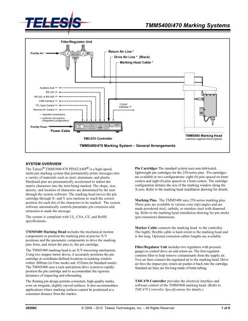
SYSTEM OVERVIEW<br />
The <strong>Telesis</strong> ® TMM5400/<strong>470</strong> PINSTAMP ® is a high-speed,<br />
multi-pin marking system that permanently prints messages into<br />
a variety of materials such as steel, aluminum, and plastic.<br />
Hardened pins are pneumatically accelerated to indent dot<br />
matrix characters into the item being marked. The shape, size,<br />
density, and location of characters are determined by the user<br />
through the system software. The marking head moves the pin<br />
cartridge through X- and Y-axis motions to reach the correct<br />
position for each dot of the characters to be marked. The system<br />
software automatically controls pneumatic pin extension and<br />
retraction to mark the message.<br />
The system is compliant with UL, CSA, CE, and RoHS<br />
<strong>specification</strong>s.<br />
TMM5400 Marking Head includes the mechanical motion<br />
components to position the marking pins at precise X/Y<br />
positions and the pneumatic components to drive the marking<br />
pins from, and return the pins to, the pin cartridge.<br />
The TMM5400 marking head is an X/Y-traversing mechanism.<br />
Using two stepper motor drives, it accurately positions the pin<br />
cartridge at coordinate-defined locations in marking window<br />
within .008mm (in Fine mode) and .032mm (in Standard mode).<br />
The TMM5400 uses a rack-and-pinion drive system to rapidly<br />
position the pin cartridge and to accommodate the rigorous<br />
dynamics of impacting and rebounding.<br />
The floating pin design permits consistent, high-quality marks,<br />
even on irregular, slightly curved surfaces. It also accommodates<br />
applications where marking surfaces cannot be positioned at a<br />
consistent distance from the marker.<br />
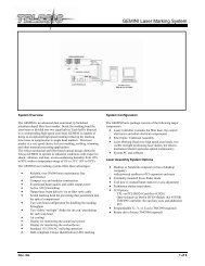
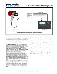
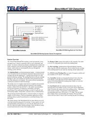
TMM5400/<strong>470</strong> Marking System – General Arrangements<br />
TMM5400/<strong>470</strong> Marking Systems<br />
Pin Cartridges The standard system uses non-lubricated,<br />
lightweight pin cartridges for the 25S-series pins. Pin cartridges<br />
are available in two configurations: eight (8) pins spaced on 6mm<br />
centers and eight (8) pins spaced on 12mm centers. The cartridge<br />
configuration dictates the size of the marking window along the<br />
X-axis. Refer to the marking head installation drawing for details.<br />
Marking Pins. The TMM5400 uses 25S-series marking pins.<br />
These pins are available in various cone (tip) angles and are<br />
made powdered steel, carbide, or stainless steel with diamond<br />
tip. Refer to the marking head installation drawing for pin stroke<br />
(pin extension) dimensions.<br />
Marker Cable connects the marking head to the controller.<br />
The highly flexible cable is hard-wired to the marking head and<br />
is 4m long. Optional extension cables lengths are available.<br />
Filter/Regulator Unit includes two regulators with pressure<br />
gauges to control drive air and return air. The first regulator<br />
contains filter to help remove contaminants from the supply air.<br />
Two air lines connect the regulated air to the marking head. Drive<br />
air fires the impact pin; return air pushes it back into the cartridge.<br />
Standard air lines are 4m long made of 6mm tubing.<br />
TMC<strong>470</strong> Controller provides the electrical interface and<br />
software control of the TMM5400 marking head. (Refer to<br />
TMC<strong>470</strong> Controller Specifications for details.)<br />
29208C © 2009 – 2012 <strong>Telesis</strong> <strong>Technologies</strong>, <strong>Inc</strong>. – All Rights Reserved 1 of 8
TMM5400/<strong>470</strong> Marking Systems<br />
SYSTEM OPTIONS<br />
• Backup Utility Software<br />
• Bar Code Scanner<br />
• Bar Code Wand<br />
• Custom Cartridges (pin quantity and spacing)<br />
• Logo/Font Generator Software<br />
• Marking Head Extension Cables<br />
• TMC<strong>470</strong> Controller Panel-mounting Bezel/Bracket Kit<br />
• TMC<strong>470</strong> Controller Wall-mounting Bracket Kit<br />
• TMC<strong>470</strong>N NEMA ® Enclosure<br />
• Upgrade Utility Software<br />
SYSTEM SETUP<br />
Complete installation procedures are provided in the TMM5400<br />
and the TMC<strong>470</strong> Installation/Maintenance Manuals. The<br />
following procedures are listed for reference only to provide a<br />
general overview of the installation process.<br />
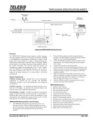
1. When designing a fixture, allow for 3-axis adjustment to<br />
aid in horizontal, vertical, and lateral alignment of the<br />
marking head.<br />
� Mount marking head to a suitable fixture using two<br />
M6-1.00 bolts. Mounting bolts must not extend<br />
into marking head more than 10mm.<br />
2. Mount filter/regulator assembly, using brackets<br />
provided, within 4 m (13.1 ft.) of marking head.<br />
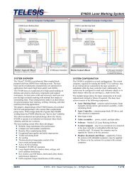
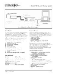
TMM5400 Detail Drawing<br />
2 of 8 29208C<br />
3. Connect drive air and return air lines to the connectors<br />
on back of marking head.<br />
4. Connect supply air to input port on filter/regulator<br />
assembly.<br />
CAUTION<br />
The TMC<strong>470</strong> is not a sealed unit. Protect it from<br />
potentially damaging conditions and contaminants. Do<br />
not block vents in bottom of case. Ensure the marking<br />
system is electrically isolated from any devices that may<br />
generate extreme electromagnetic interference (EMI).<br />
5. Locate controller as close as practical to marking head.<br />
Standard marker cable length is 4 m (13 ft.).<br />
6. Install the controller as a table-top, wall-mounted, panelmounted,<br />
or enclosure-mounted unit, as applicable.<br />
7. Ensure controller power switch is OFF.<br />
8. Connect marker cable to controller.<br />
9. Connect power cable to controller.<br />
10. Position controller power switch to ON.<br />
11. Start marking system software.<br />
12. Adjust pin stroke, drive air, and return air for impact depth.
TMM5400 MARKING HEAD<br />
Specifications<br />
The TMM5400 marking head <strong>specification</strong>s are subject to<br />
change without prior notice.<br />
Dimensions (H x W x D) ........... 140 x 127 x 104 mm [no cartridge]<br />
194 x 127 x 104 mm [with cartridge]<br />
Weight .................................... 2.73 kg (6.01 lb.)<br />
[without pins, cartridge or tooling]<br />
Operating Temp. .................... 0° to 50°C (32° to 122° F),<br />
non-condensing<br />
Humidity ................................. 10% to 80%<br />
Air Supply ............................... Clean and dry, 4.2 to 8.3 bars<br />
(60 to 120 psi)<br />
Air Consumption ..................... 0.15 L/sec (0.32 SCFM) idle<br />
0.28 L/sec (0.60 SCFM) marking<br />
X-axis Travel .......................... 36 mm<br />
Y-axis Travel .......................... 13 mm<br />
Marking Area .......................... see TMM5400 Detail Drawing<br />
Maximum Pin Stroke .............. 10.0 mm<br />
Number of Impact Pins ........... 8 (spaced 6 mm on centers) or<br />
8 (spaced 12 mm on centers)<br />
Number of Rows of Pins ......... 1<br />
Pin Types ............................... 25S-series with various<br />
cone (tip) angles<br />
Pin Material ............................ Powdered Metal or Carbide or<br />
Stainless Steel with Diamond Tip<br />
TMM5400/<strong>470</strong> Marking Systems<br />
Marking Characteristics<br />
The TMM5400 can produce characters as small as .13mm high.<br />
Text strings may be rotated 180° to print inverted. Characters can<br />
printed with resolutions from 5 dots/cm to 75 dots/cm for an<br />
engraved look. The depth of mark can be adjusted over a<br />
significant range by adjusting the pin stroke and, to a lesser extent,<br />
by adjusting the drive air pressure. Three marking modes are<br />
available to optimize quality and speed. Raster mode prints sideto-side,<br />
indexing downward one row at a time. Matrix mode prints<br />
up and down, indexing one column at a time. Continuous mode<br />
prints with only one pin at a time.<br />
Three marking modes are available to optimize quality and<br />
speed. Raster mode prints side-to-side, indexing downward one<br />
row at a time. Matrix mode prints up and down, indexing one<br />
column at a time. Continuous mode prints with only one pin at a<br />
time tracing the character shape.<br />
Marking Speeds<br />
The system is capable of marking 16 characters per second (two<br />
characters per pin per second) using 5x7 font, 3mm high<br />
characters. Speeds will vary slightly depending on the selected<br />
character size, style, and dot density. Specific times can be<br />
verified by a <strong>Telesis</strong> representative.<br />
Marking Noise<br />
Although every attempt is made to reduce noise, the material<br />
being marked significantly influences the noise level. For<br />
example, marking a solid lead block produces less noise than<br />
marking a thin-walled steel pipe.<br />
Pin Life<br />
Pin life depends largely on the type of material being marked,<br />
how hard or abrasive it is, and the required marking depth. On<br />
typical metals with a hardness of Rockwell Rb47, marking at a<br />
depth of .127mm, powdered steel pins average about 3 million<br />
impressions before needing sharpened.<br />
29208C 3 of 8
TMM5400/<strong>470</strong> Marking Systems<br />
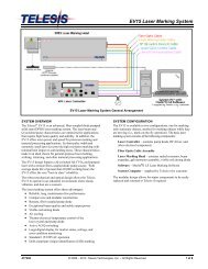
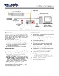
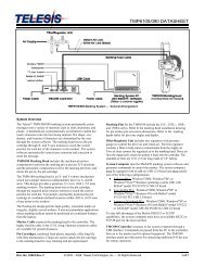
TMC<strong>470</strong> Controller Dimensions – Table-top and Wall-mounted Configurations<br />
TMC<strong>470</strong> CONTROLLER<br />
The TMC<strong>470</strong> controller may be installed as a table-top unit, a<br />
wall-mounted unit, a panel-mounted unit, or an enclosuremounted<br />
unit. All configurations provide features and<br />
connectivity for external communications. Differences occur<br />
only in the mounting configuration.<br />
TMC<strong>470</strong> Specifications<br />
The TMC<strong>470</strong> Controller <strong>specification</strong>s are subject to change<br />
without prior notice.<br />
Compliance .................. CE, RoHS<br />
Configurations .............. Table-top, Wall-mounted, Panelmounted,<br />
or Enclosure-mounted<br />
Rating ........................... NEMA 1 (I.P. 30) table-top or<br />
wall-mounted<br />
NEMA 12 (I.P. 65) panel-mounted<br />
using customer-supplied panel<br />
NEMA 12 (I.P. 65) using <strong>Telesis</strong>supplied<br />
TMC<strong>470</strong>N enclosure<br />
Dimensions .................. refer to TMC<strong>470</strong> Mounting Drawings<br />
Weight ......................... 3.69 lb. (1.68 kg) controller only<br />
3.90 lb. (1.77 kg) with wall-mount kit<br />
5.52 lb. (2.51 kg) with panel-mount kit<br />
28.1 lb. (12.77 kg) with TMC<strong>470</strong>N<br />
enclosure<br />
4 of 8 29208C<br />
TMC<strong>470</strong> Specifications (continued)<br />
Op. Temperature ......... 32° to 122° F (0° to 50°C)<br />
Op. Humidity ................ 10% to 80% non-condensing<br />
Cooling ......................... Internal, thermostat-controlled fan<br />
Power Requirements .... 95 to 250 VAC, 2 amps,<br />
50-60 Hz, single phase<br />
Communications .......... TTL, Discrete I/O,<br />
RS232, RS485, TCP/IP, and<br />
USB (<strong>data</strong> backup and <strong>data</strong> transfer)<br />
Input Signals ................ Twelve (12) total, optically isolated:<br />
8 dedicated, 1 programmable,<br />
3 available<br />
10 VDC (minimum voltage)<br />
30 VDC (maximum voltage)<br />
12 to 24 VDC (nominal voltage)<br />
2.3 mA @ 12VDC; 4.9 mA @ 24VDC<br />
(nominal current)<br />
Output Signals ............. Six (6) total, optically isolated:<br />
4 dedicated, 2 available<br />
0.25 amps (maximum current)<br />
0.50 ohms (maximum On resistance)<br />
40 VDC (maximum line voltage)<br />
12 to 24 VDC (nominal line voltage)
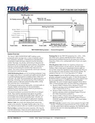
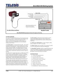
TMC<strong>470</strong> Controller Dimensions – Panel-mounted Configuration<br />
Environmental Considerations<br />
The following environmental considerations must be taken into<br />
account when installing the TMC<strong>470</strong> Controller.<br />
Contaminants. The vented TMC<strong>470</strong> is rated NEMA 1 (IP30)<br />
and contains a thermostatically-controlled, variable speed fan.<br />
Accordingly, in environments where solid and/or liquid<br />
contaminants are present, the possibility exists that these<br />
contaminants can be drawn into the TMC<strong>470</strong> controller and<br />
possibly result in failure. For that reason, in these types of<br />
environments, the controller must be located in a sealed<br />
industrial enclosure. To facilitate such installations, <strong>Telesis</strong><br />
offers on optional panel mounting kit for use with an appropriate<br />
customer-supplied panel or enclosure. <strong>Telesis</strong> also offers an<br />
optional TMC<strong>470</strong>N NEMA 12 (I.P. 65) enclosure in which the<br />
controller can be mounted.<br />
EMI Susceptibility. Although the system has been found to be<br />
in compliance with pertinent susceptibility standards, care<br />
should be taken when installing near welders and other extreme<br />
generators of electromagnetic interference (EMI). Particular care<br />
should be taken to ensure welder currents are not injected<br />
through the marking head chassis. The marking head chassis is<br />
connected to the electrical service earth ground through the<br />
marking head cable. The marking head should be electrically<br />
isolated from all surfaces which could become part of a welder<br />
current path.<br />
TMM5400/<strong>470</strong> Marking Systems<br />
TMC<strong>470</strong>-based System Software<br />
The system software is permanently installed in the controller.<br />
It provides the user interface for the operator to control the<br />
marker. The software also provides a library for storing, loading,<br />
and editing user-defined patterns. Patterns are files stored in the<br />
controller’s memory. Depending on the size of the pattern files,<br />
the controller can store up to 200 patterns. Each pattern contains<br />
one or more fields; each field defines a single object. Printable<br />
objects may be created to define text strings, arc-text strings,<br />
geometric shapes , graphics, and machine-readable <strong>data</strong> matrix<br />
symbols. Non-printable objects may be defined to specific<br />
commands to the marker (e.g., Pause, Go to, Input, or Output).<br />
Printable text fields may include alphanumeric characters,<br />
symbols, and special message flags. Message flags<br />
automatically insert <strong>data</strong> into the text string, such as serial<br />
numbers, times, dates and user-defined codes.<br />
29208C 5 of 8
TMM5400/<strong>470</strong> Marking Systems<br />
TMC<strong>470</strong> Controller Dimensions – Enclosure-mounted Configuration<br />
Interface Panel<br />
The back panel of the controller provides various ports for<br />
connecting the marker, host computers, logic controllers,<br />
optional accessories, and remote I/O devices. See below.<br />
Serial Interface. The Comm 1 and Comm 2 Ports allow<br />
connection to remote serial devices such as a host computer or a<br />
bar code scanner. See Host Communications for details.<br />
Discrete I/O Interface. The optically-isolated I/O Port allows<br />
you to connect a Programmable Logic Controller (PLC) or other<br />
DC I/O source for remotely controlling marker operations. See<br />
Discrete I/O Controls for details.<br />
TTL Interface. The TTL Port allows the system to connect<br />
with a simple contact closure circuit such as a remote push<br />
button station or foot pedal switch. These types of devices can<br />
remotely control Start Print and Stop Print operations.<br />
TCP/IP Interface. The Ethernet Port typically connects to a<br />
PC over a local area network (LAN). It allows you to define the<br />
controller as a client or a server socket using <strong>Telesis</strong> Extended<br />
Protocol. See Host Communications for details.<br />
USB Interface. The USB Port allows you to connect a memory<br />
stick/flash drive for pattern storage/retrieval and for software<br />
upgrades.<br />
6 of 8 29208C<br />
Discrete I/O Controls<br />
The TMC<strong>470</strong> is configured for 12 VDC to 24 VDC I/O only and<br />
is provided to connect a PLC or other DC I/O source. The<br />
optically-isolated I/O Port allows you to remotely select and load<br />
patterns, start printing, stop printing, place the marker online, and<br />
monitor the system output signals. Cable connectors and<br />
connector pins are supplied with the controller for constructing<br />
appropriate interface cables.<br />
Input Signals. These input signals provide the following controls:<br />
INPUT COMM .................. For all inputs (+ or – supply)<br />
START PRINT ................. Begins print cycle<br />
STOP .............................. Stops the print cycle<br />
SEL_0 thru _6 * ................ Remotely selects & loads up to<br />
127* pattern files<br />
SPARE_1, 2, 3 ................. Three (3) spares for custom<br />
applications<br />
* System software allows SEL_6 signal to be configured for remotely<br />
selecting patterns or for remotely placing the marker online. If used<br />
for marker online, pattern selection is reduced to 63 patterns (max).<br />
Output Signals. These output signals indicate the following states:<br />
OUTPUT COMM .............. For all outputs (+ or – supply)<br />
DONE ............................. Print cycle is complete<br />
READY ........................... System ready for message or for<br />
start print command<br />
PAUSED ......................... System paused (waiting timeout or<br />
command)<br />
NO FAULT ...................... System status (normal or fault<br />
detected)<br />
SPARE_1, 2 ..................... Two (2) spares for custom applications
Host Communications<br />
The marking system software allows you to configure<br />
communication parameters to transmit and receive <strong>data</strong> to and<br />
from a host computer. To provide maximum integration<br />
flexibility, the system software supports RS-232 and RS-485<br />
serial interfaces and Ethernet TCP/IP interfaces. The system<br />
software also provides two protocol choices: Programmable<br />
Protocol and Extended Protocol.<br />
RS-232 Interface. The serial (RS-232) communications<br />
interface is most often used with remote devices such as host<br />
computers, terminals, or bar code scanners. The Comm 1<br />
RS-232 interface supports both <strong>Telesis</strong> Extended Protocol and<br />
<strong>Telesis</strong> Programmable Protocol. The Comm 2 RS-232 interface<br />
supports only <strong>Telesis</strong> Programmable Protocol.<br />
RS-485 Interface. The RS-485 interface is normally used for<br />
long transmission distances or multi-drop networks of up to 31<br />
TMC<strong>470</strong> controllers. You must use <strong>Telesis</strong> Extended Protocol<br />
with the RS-485 interface.<br />
The following describes the serial <strong>data</strong> character format on all<br />
transmissions to and from the TMC<strong>470</strong> Controller.<br />
• Asynchronous<br />
• 1200, 2400, 4800, 9600, 19200, 38400, or 115200 Baud<br />
• 1 or 2 Stop Bits<br />
• 7 or 8 Data Bits<br />
• None, Even or Odd Parity<br />
TCP/IP Interface. The Ethernet (TCP/IP) interface is most<br />
often used with host computers communicating over a local area<br />
network (LAN). You must use <strong>Telesis</strong> Extended Protocol with<br />
the TCP/IP interface.<br />
The Port parameter identifies the host computer socket that is<br />
assigned to the marking system. If more than one marking<br />
system is installed in a network configuration, each system must<br />
use a separate and unique port number. The Address parameter<br />
identifies the IP address of the host computer. The marking<br />
system software supports both fixed addressing and dynamic<br />
addressing.<br />
TMM5400/<strong>470</strong> Marking Systems<br />
Programmable Protocol. Use this protocol where very simple<br />
one-way communications are required (such as with bar code<br />
scanners). Programmable Protocol provides no error checking or<br />
acknowledgment of the transmitted <strong>data</strong>. Note that XON/XOFF<br />
Protocol applies even when Programmable Protocol is selected.<br />
Starting Character specifies where the software begins to<br />
count character positions. This number must be entered in<br />
decimal format (e.g., "2" for ASCII Start of Text "STX").<br />
Terminating Character identifies the end of transmitted<br />
string (usually "13" for ASCII carriage return character).<br />
Character Position counted from the starting character<br />
ignoring all characters preceding it.<br />
Character Length accepts variable length messages (if set<br />
to 0) or messages of a pre-specified, fixed number of<br />
characters.<br />
Ignore Character identifies the character to ignore when sent<br />
from the host (usually "10" for ASCII line feed character)).<br />
Message Type allows message-type recognition which<br />
defines how the marking system will use <strong>data</strong> it receives from<br />
the host.<br />
1 Message type 1 overwrites the first line of the first<br />
text field with <strong>data</strong> extracted from the host<br />
P Message type P loads a specific pattern identified by<br />
<strong>data</strong> extracted from host<br />
Q Message type Q updates the text in the first query<br />
buffer with <strong>data</strong> extracted from the host<br />
V Message type V updates the first variable text flag<br />
found in the pattern with <strong>data</strong> extracted from the host<br />
0 Message type 0 (zero) indicates that host will provide<br />
message type, field number (if applicable), line<br />
number (if applicable), and <strong>data</strong>; delegates message<br />
type selection to the host on message-by-message<br />
basis. The host message must use the format:<br />
Tnn<br />
where:<br />
T = 1, P, Q, or V to indicate message type<br />
nn = two-digit field number or query text buffer<br />
where <strong>data</strong> will be placed.<br />
Note: Not used with Message Type P.<br />
= For Message Type P, indicates the<br />
pattern name to be loaded.<br />
For Message Types 1, Q, or V, indicates<br />
the <strong>data</strong> to be inserted into the field or the<br />
query text buffer, as applicable.<br />
29208C 7 of 8
TMM5400/<strong>470</strong> Marking Systems<br />
Host Communications (continued)<br />
Extended Protocol. This protocol selection includes error checking and transmission acknowledgment. It should be used in applications<br />
where serial communication is a vital part of the marking operation. All communications are carried out in a parent/child relationship with<br />
the host being the parent. Only the host has the ability to initiate communications. If the host does not receive a response within three<br />
seconds, it should re-transmit its original message. If no response is received after three tries, it should declare the link to be down.<br />
The following describes the Extended Protocol message format<br />
as sent from the host to the TMC<strong>470</strong> controller.<br />
SOH TYPE [##] STX [DATA] ETX BCC CR<br />
where:<br />
SOH ASCII Start of Header character (001H). The controller<br />
ignores all characters received prior to the SOH.<br />
TYPE A single, printable ASCII character that defines the<br />
meaning (type) and content of the message<br />
downloaded from the host, where:<br />
1 Message Type 1 overwrites a specific field in<br />
currently loaded pattern with <strong>data</strong> supplied in the<br />
host message. See [DATA] for details.<br />
P Message Type P specifies the pattern name to be<br />
loaded for printing. See [DATA] for details.<br />
Q Message Type Q updates a specific query buffer<br />
with <strong>data</strong> supplied in the host message.<br />
See [DATA] for details.<br />
V Message Type V updates the variable text in a<br />
specific text field of the currently loaded pattern<br />
with <strong>data</strong> supplied in the host message.<br />
See [DATA] for details.<br />
O Message Type O resets marker and places it<br />
online<br />
G Message Type G initiates a print cycle to mark the<br />
currently loaded pattern<br />
I Message Type I requests the marker return the<br />
status of standard output and input signals. The<br />
system will return a hexadecimal code for the 6<br />
output signals and 12 input signals in the following<br />
format:<br />
OO;III<br />
where:<br />
bit 1 READY 0x01<br />
bit 2 DONE 0x02<br />
bit 3 PAUSED 0x04<br />
bit 4 NO_FAULT 0x08<br />
bit 5 SPARE_1 0x10<br />
bit 6 SPARE_2 0x20<br />
bit 1 START 0x001<br />
bit 2 STOP 0x002<br />
bit 3 SEL_0 0x004<br />
bit 4 SEL_1 0x008<br />
bit 5 SEL_2 0x010<br />
bit 6 SEL_3 0x020<br />
bit 7 SEL_6 * 0x040<br />
bit 8 SEL_4 0x080<br />
bit 9 SEL_5 0x100<br />
bit 10 SPARE_1 0x200<br />
bit 11 SPARE_2 0x400<br />
bit 12 SPARE_3 0x800<br />
Note: Input SEL_6 may be configured<br />
to place machine online (default)<br />
or for Remote Pattern Selection.<br />
8 of 8 29208C<br />
[##] Optional two-digit ASCII number that specifies the<br />
Station ID of the controller when used in multi-drop<br />
network applications. The Station ID may range from<br />
00-31. Note that “00” is reserved for applications where<br />
only one controller is used. In such applications, this<br />
field may be eliminated and “00” will be assumed.<br />
STX ASCII Start of Text Character (002H).<br />
[DATA] Optional character string that may be required for<br />
certain message types (e.g., Type 1, P, Q, and V).<br />
Typically, <strong>data</strong> is sent in the format:<br />
nn.<br />
where:<br />
nn = two-digit field number or query text buffer<br />
where <strong>data</strong> will be placed.<br />
Note: Not used with Message Type P.<br />
= For Message Type P, indicates the<br />
pattern name to be loaded.<br />
For Message Types 1, Q, or V, indicates<br />
the <strong>data</strong> to be inserted into the field or the<br />
query text buffer, as applicable.<br />
ETX ASCII end of text character (003H).<br />
BCC Optional Block Check Code that is generated and sent<br />
to improve link reliability by providing fault detection.<br />
The BCC is calculated by taking an eight bit addition of<br />
the TYPE and DATA TEXT characters and transmitting<br />
them as a three digit ASCII decimal number in the<br />
range from 000 to 255. If the sum is greater than 255,<br />
the most significant bit overflows and is discarded.<br />
CR ASCII Carriage Return Character (00DH).<br />
TRADEMARKS<br />
<strong>Telesis</strong> and PINSTAMP are registered trademarks of <strong>Telesis</strong><br />
<strong>Technologies</strong>, <strong>Inc</strong>. in the United States.<br />
NEMA is the registered trademark and service mark of the<br />
National Electrical Manufacturers Association.