Pneumatic cylinders - Duncan Rogers
Pneumatic cylinders - Duncan Rogers Pneumatic cylinders - Duncan Rogers
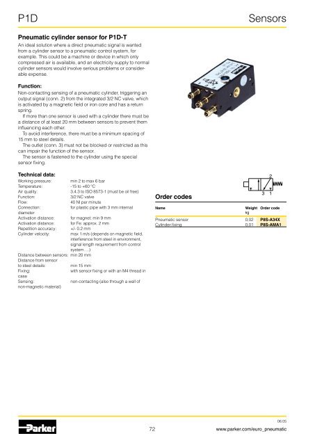
P1DSensorsPneumatic cylinder sensor for P1D-TAn ideal solution where a direct pneumatic signal is wantedfrom a cylinder sensor to a pneumatic control system, forexample. This could be a machine or device in which onlycompressed air is available, and an electricity supply to normalcylinder sensors would involve serious problems or considerableexpense.Function:Non-contacting sensing of a pneumatic cylinder, triggering anoutput signal (conn. 2) from the integrated 3/2 NC valve, whichis activated by a magnetic field or iron core and has a returnspring.If more than one sensor is used with a cylinder there must bea distance of at least 20 mm between sensors to prevent theminfluencing each other.To avoid interference, there must be a minimum spacing of15 mm to steel details.The outlet (conn. 3) must not be blocked or restricted as thiscan impair the function of the sensor.The sensor is fastened to the cylinder using the specialsensor fixing.Technical data:Working pressure: min 2 to max 6 barTemperature: -15 to +60 °CAir quality:3.4.3 to ISO 8573-1 (must be oil free)Function:3/2 NC valveFlow:40 Nl per minuteConnection:for plastic pipe with 3 mm internaldiameterActivation distance: for magnet: min 9 mmActivation distance: for Fe: approx. 2 mmRepetition accuracy: +/- 0.2 mmCylinder velocity: max 1 m/s (depends on magnetic field,interference from steel in environment,signal length requirement from controlsystem….)Distance between sensors: min 20 mmDistance from sensorto steel details:min 15 mmFixing:with sensor fixing or with an M4 thread incaseSensing:non-contacting (also through a wall ofnon-magnetic material)Order codesNameWeight Order codekgPneumatic sensor 0,02 P8S-A34XCylinder fixing 0,01 P8S-AMA13217206.05www.parker.com/euro_pneumatic
P1DSensorsDimensionsActive surface forsensing iron coreIndication40,33,534M49,3212841,214,5 1,616,71821,33,99,114,318,215 1517Cylinder fixing7306.05www.parker.com/euro_pneumatic
- Page 21: P1DExample 1 : Which tube diameter
- Page 24 and 25: P1DCylinderSafety instructions for
- Page 26 and 27: P1DStandard cylinderP1D StandardCAD
- Page 28 and 29: P1DThe simple and complete order ke
- Page 30 and 31: P1DCylinderP1D cylinders with pisto
- Page 32 and 33: P1DCylinderFactory-fitted sensorsAl
- Page 34 and 35: P1DCylinderExtended piston rodAll c
- Page 36 and 37: P1DCylinderThrough piston rodAll P1
- Page 38 and 39: P1DP1D Clean with built-in sensorTh
- Page 40 and 41: P1DCylinderP1D CleanThe order numbe
- Page 42 and 43: P1DCylinderP1D Flexible PortingThe
- Page 44 and 45: P1DCylinderCombine P1D Clean and P1
- Page 46 and 47: P1DTechnical dataWorking pressurema
- Page 48 and 49: P1DPiston rod lockingP1D-LP1D-DP1D
- Page 50 and 51: P1DFastening in positionPiston rod
- Page 52 and 53: P1DRod Guidance ModulesAluminium bo
- Page 54 and 55: P1DRod Guidance ModulesL1 + SA1B1B4
- Page 56 and 57: IP1DMountingsCylinder mountingsType
- Page 58 and 59: P1DMountingsCylinder mountingsType
- Page 60 and 61: P1DMountingsCylinder mountingsType
- Page 62 and 63: P1DMountingsPiston rod mountingsTyp
- Page 64 and 65: P1DMountingsCombinationsType Descri
- Page 66 and 67: P1DMountingsCombinationsType and de
- Page 68 and 69: P1DSensorsElectronic sensorsReed se
- Page 70 and 71: P1DSensorsConnecting cables with on
- Page 74 and 75: P1DSeal kitsP1D Seal kitsComplete s
- Page 76 and 77: P1DSpare PartsOrder key, spare part
- Page 78 and 79: P1DOrder code keyThere is a P1D cyl
- Page 80 and 81: P1DOrder code keyCylinder versionS
- Page 82: P1DOrder code keyInformation notes1
P1DSensors<strong>Pneumatic</strong> cylinder sensor for P1D-TAn ideal solution where a direct pneumatic signal is wantedfrom a cylinder sensor to a pneumatic control system, forexample. This could be a machine or device in which onlycompressed air is available, and an electricity supply to normalcylinder sensors would involve serious problems or considerableexpense.Function:Non-contacting sensing of a pneumatic cylinder, triggering anoutput signal (conn. 2) from the integrated 3/2 NC valve, whichis activated by a magnetic field or iron core and has a returnspring.If more than one sensor is used with a cylinder there must bea distance of at least 20 mm between sensors to prevent theminfluencing each other.To avoid interference, there must be a minimum spacing of15 mm to steel details.The outlet (conn. 3) must not be blocked or restricted as thiscan impair the function of the sensor.The sensor is fastened to the cylinder using the specialsensor fixing.Technical data:Working pressure: min 2 to max 6 barTemperature: -15 to +60 °CAir quality:3.4.3 to ISO 8573-1 (must be oil free)Function:3/2 NC valveFlow:40 Nl per minuteConnection:for plastic pipe with 3 mm internaldiameterActivation distance: for magnet: min 9 mmActivation distance: for Fe: approx. 2 mmRepetition accuracy: +/- 0.2 mmCylinder velocity: max 1 m/s (depends on magnetic field,interference from steel in environment,signal length requirement from controlsystem….)Distance between sensors: min 20 mmDistance from sensorto steel details:min 15 mmFixing:with sensor fixing or with an M4 thread incaseSensing:non-contacting (also through a wall ofnon-magnetic material)Order codesNameWeight Order codekg<strong>Pneumatic</strong> sensor 0,02 P8S-A34XCylinder fixing 0,01 P8S-AMA13217206.05www.parker.com/euro_pneumatic


