500 Watt Subwoofer Amplifier User Manual - Ljudia
500 Watt Subwoofer Amplifier User Manual - Ljudia
500 Watt Subwoofer Amplifier User Manual - Ljudia
- No tags were found...

Create successful ePaper yourself
Turn your PDF publications into a flip-book with our unique Google optimized e-Paper software.
1.) Low-Level inputs (Left/Right)RCA- and balanced XLR style jacks what will accept standard line level inputs from a pre-amp level source. Theywill accept a stereo signal and internally combine it into mono. Both left and right input jacks must beconnected to the source in order to drive the amplifier to full output.2.) Low-Level outputs (Left/Right)This balanced XLR output allows the low level input signal to be daisy chained through the internal preamps toother amplifiers or powered satellites with no alternation (EQ) to the original signal.3.) LevelThis control will match the amplifier’s input sensitivity to the output of the pre-amp source. If the source has avariable control, we recommend that the user spend a moment or two determining the best balance betweenthe two controls. When a balance is found between low noise, linear level control, and sufficient level to drivethe amp to the required output, the level knob can be considered to be the “volume control” for thesubwoofer or full range system.4.) BypassThis two position (ON or OFF) switch gives in ON mode full frequency to the amp which can be used as a fullrange amplifier (subsonic- and phase switch can still be used).In OFF mode will the signal supply the sweep control and the amp is suitable for subwoofer system.5.) HPFThis two position (ON or OFF) switch gives in ON mode a slight decreasing of the treble from approx 200 Hz andup (only in bypass ON mode).6.) SweepThis control works only in bypass OFF mode and is used to establish the highest frequency that the subwooferwill reproduce and has a range between 30 to 200Hz with slop of 24 dB per octave. If you are using the systemfor music and your main speakers have good bass capability, you could set the control to a fairly low value at40, 60, or even 100 Hz. If the main speakers are smaller or do not have much bass output, set the controlhigher. Experiment with the amount of “overlap” that you experience when all speakers are playing in thesame range. This can be helpful when integrating the subwoofer with the rest of the system and with the room.7.) LPFThis two position (ON or OFF) switch gives in ON mode a slight decreasing of the bass from approx 40 Hz anddown. It is useful to remove the extremely low disturbing frequencies (only in bypass ON mode).8.) PhaseThis two position (NOR = 0° and REV = 180° phase) switch helps to compensate for different in the acousticaland electrical characteristics between the subwoofer or full range system and the main system speakers. Therelative locations of speaker in the system can cause significant disturbances in speaker in the system due totime delay issues, or the destructive phase interferences that can occur at certain frequencies. The use of thisswitch in conjunction with altering the location the location of the subwoofer or full range speaker can have adramatic effect on system integration. The “NOR” setting would be considered the normal or default setting,but be sure to experiment during system set-up. This feature works regardless of the bypass mode.9.) SubsonicThis four position (OFF, 20, 35 and 50 Hz) switch is very useful to eliminate disturbing low frequencies. The bestis to experiment for best results. This feature works regardless of the bypass mode.10.) Stereo-MonoThis two position (Stereo-Mono) switch gives in STEREO mode +3 dB and in MONO mode can the amp only besupplied by the left inputs.(3)
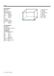
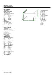
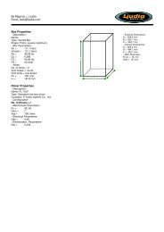
11.) Power input, Fuse Sled and voltage SwitchConnect the supplied standard IEC AC power cable here. Be sure to confirm and install the properly rated fusewhen replacing the fuse or changing the operation voltage. Slide to change the operation voltage from 115 to230 Volts.12.) PowerSwitches on the DSW-<strong>500</strong>NNote: The power led is normally green. When change to red is the limiter protection activated.NOTES ABOUT HUMWhile the DSW-<strong>500</strong>N has designed to minimize the possibility of hum in the subwoofer or full range system, itstill possible that a hum will occur in rare circumstances. Its safety grounding can create a path for smallamounts of 50 to 60 Hz (depending of the frequencies in the power jackets) energy to travel trough the linelevelaudio system. To reduce hum, all connections can be connected to a single grounded outlet.Rated Power Output:Signal to Noise Ratio:Input Impedance:Sweep Control:Subsonic Filters:Other Controls:Dimensions:Power Requirements:Weight:SPECIFICATIONS:300 watts RMS into 8 ohms @ 0.1% THD<strong>500</strong> watts RMS into 4 ohms @ 1.0% THD90 dB A-weighted12K ohms30 – 200 Hz, 24 dB per octaveOFF, 20, 35, 50 HzPhase 0° (NOR) or 180° (REV), LPF-FilterHPF-Filter, Stereo-Mono- and Bypass switch304 mm W x 304 mm H x 135 mm D115/230 VAC, 50/60 Hz, 800 WFuse 8 AT, 250V (115VAC)Fuse 4AT, 250V (230VAC)8, 9 kgImportant Safety InstructionsTo reduce the risk of electric shock, do not remove cover. No user serviceable parts inside. Refer serving to qualifiedpersonnel. To reduce the risk of fire and shock do not expose unit to rain or moisture. The unit should be connected anearth grounded AC electrical socket. The unit should be operated in a well ventilated area. Minimum clearance is 5 cm fromthe ventilation openings.Note: Before starting, make sure that the voltage selector is in the correct position depending on the power outlet.(4)