Keller â Publications > Jet Grouting - Smet-Keller
Keller â Publications > Jet Grouting - Smet-Keller
Keller â Publications > Jet Grouting - Smet-Keller
- No tags were found...

You also want an ePaper? Increase the reach of your titles
YUMPU automatically turns print PDFs into web optimized ePapers that Google loves.
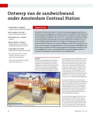
Quality assurance in <strong>Jet</strong> <strong>Grouting</strong>for a deep seated slabin AmsterdamDipl.-Ing. Thomas Passlick, <strong>Keller</strong> Grundbau GmbH, Bochum,Dr.-Ing. Karsten Doerendahl, <strong>Keller</strong> Grundbau GmbH, Maintal,By means of further developed machines and techniques and with growing experiencesin jet grouting, the challenge of this building method becomes moreand more complex. To keep the concerning risks as low as possible, the requirementson the quality assurance continuously increase.The construction of a 37.0m deep seated slab for the Amsterdam metro stationVijzelgracht in marine clay represents such a complex task. This paper summarisesthe required measures of quality assurance. In particular a new hydraulicmeasuring device is introduced with which it was possible to detect the columndiameter of 2.6m at a depth of 37.0m during the production process and with avery high accuracy.1. IntroductionThe production of a deep seated slab using the jet grouting method surely is one of the mostchallenging fields of application for this method. Due to this the risks are very high. Theserisks are based on the method itself (e.g. as in most cases the treated soil cannot be controlledvisually) and on the special site conditions influencing the production parameters.If columns have to be made at large depth and in a soil which is hard to erode, the qualityassurance is very important in the phases of design and construction. It helps keeping therisks at a low level and thus makes some project possible to be realized. Last but not leastthe collapse of the Nicoll Highway building pit shows quite plainly the possible effect of disregardingthe quality assurance, although this was not one of the main reasons.The measures of quality assurance described in this paper concern a special building projectand do not have a general character. They intend to demonstrate the measures that arenecessary to achieve and verify a column diameter of 2.60m at a depth of 37m in marineEem clay.
Dipl.-Ing. Thomas Passlick, Dr.-Ing. Karsten Doerendahl, <strong>Keller</strong> Grundbau GmbH2. The jet grouting process (SOILCRETE ® )The jet grouting process is recognized as a cement soil stabilization. The soil around theborehole is eroded with the aid of air-shrouded high pressure cutting jets of water or cementsuspension having a nozzle exit velocity ≥ 100m/sec.The eroded soil is rearranged and mixed with the cement suspension. The soil-cement mixis partly flushed out to the top of the borehole through the annular space between the jetgrouting rods and the borehole. Different geometrical configurations of elements can beproduced. The erosion distance of the jet varies according to the soil type, the kind of processand the jetting fluid and may reach up to 2.5m in case of using the standard methods.In contrast to the conventional ground stabilization methods jet grouting may be used forstabilisation and sealing of all kinds of soil ranging from loose sediments to clay. This alsoapplies to non homogeneous soil formations and changing soil layers, including organic material.Three different jet grouting methods exist. The method to be used is determined by theprevailing soil conditions, the geometrical form and the required quality of the jet groutingelements.Single System (Soilcrete ® –S)Single direct process operates with a grout jet of min. 100m/sec. exit velocity for simultaneouscutting and mixing of the soil without an air shroud. The Single System is used for smallto medium sized jet grout columns.Double System (Soilcrete ® –D)Double direct process operates with a grout jet of min. 100m/sec. exit velocity for simultaneouscutting and mixing of the soil. To increase the erosion capability and the range of thegrout jet, air shrouding by means of shaped air jet nozzle is used. The Double System ismainly used for panel walls, underpinning and sealing slabs.Fig. 1: Application limits for grouting techniques3
Quality assurance in <strong>Jet</strong> <strong>Grouting</strong> for a deep seated slab in Amsterdammonitoring equipment to record, interpret and visualize the relevant parameters during theproduction process. In addition, a measuring system was necessary to verify the position andthe diameter of the jet grout column directly after the production phase to guarantee apermanent constancy of fulfilling the quality requirements.To point out the importance of the topic, a short look on the collapse of the Nicoll Highwayon April 2005 should be done, without giving a complete explanation of the main reasons.The following facts clearly indicate that the level of quality assurance was definitely too lowfor such a huge building project: There was neither electronic on-board monitoring equipmentnor a continuous proof of the achieved column diameter except for the rare coringdone at every 1000 linear meters of jet grouting. A long time before the construction failed,the measured deflections of the diaphragm wall showed that the compressive strain in thetreated soil have far exceeded the design parameters.This should clearly alert us to the importance of the quality assurance during the design andproduction of both types of slabs, the watertight one and the static one. This is valid particularlyfor jetting at large depth and in cohesive soils.4.1 Field of test columnsIn the area of the Rokin metro station several test columns at a depth of 32m were made toverify the assumed parameters for the jet grouting and to verify the column diameter respectively.As a result the required drilling deviation had to be changed from 0.5% to 1%.Due to the geology and the obstacles in the ground a deviation of 0.5% could economicallynot be realized.Furthermore the standard jet grouting methods (Double System) did not show the sameresults at the Rokin metro station as in the PIP test columns mentioned by VAN DERSTOEL (2001). To reach the same diameters much higher energy would have been needed.With the Superjet method diameters > 2.60m could have been produced.Additionally these test columns showed that the new measuring device used by KELLER wasable to clearly identify all the produced column diameters.4.2 The choice of production parametersAs mentioned above, several jet grouting methods exist, each one having its own advantagesand disadvantages. It is the client´s and the experienced contractor’s responsibility to choosethe right method that represents the most economic alternative of low risk.On the one hand the mechanical properties of the treated soil (e.g. homogeneity, strength,stiffness) depend on the jet grout method and its parameters, on the other hand this dependson the local soil conditions, as the soil is always a component of the jet grouted mass.In view of the jet grouting slab in Amsterdam, this means a reduction of the strength due tothe marine clay unless the production process will be separated into two phases. The first iscutting the clay with a grout of low cement content and afterwards filling the volume with agrout of high cement content. This can be done in one step using the triple system or intwo sequenced steps using the single or double system. At the metro station Vijzelgracht theclay was first cut with a modified double system (Superjet) in two sequenced phases. Thisguaranteed the required combination of a large column diameter with a high strength in thetreated soil.6
Dipl.-Ing. Thomas Passlick, Dr.-Ing. Karsten Doerendahl, <strong>Keller</strong> Grundbau GmbHBasically there are several different machine parameters needed to achieve a certain hydraulicenergy, so several combinations of parameters are possible to produce the same hydraulicenergy. Finding out the right combination of parameters requires a lot of experience.Field tests should be made to verify these parameters.At the metro station Vijzelgracht an on-board electronic monitoring equipment was used torecord, interpret and visualize the following production parameters: time, depth, lift rate,speed of rotation, drilling pressure, grout pressure, grout flow, air pressure and air flow.Due to a clearly arranged visualization a prompt evaluation could be done for each singlecolumn. So the flexibility was given to be responsive to discrepancies and thus to adjust theproduction process.<strong>Jet</strong> grouting is defined by cutting the soil with a very high pressure. This assumes that a permanentflow of the grout-soil mixture (spoil) has to be monitored to prevent heaves or settlementsof the adjacent buildings. The viscosity of the spoil again depends on the chosenproduction method and the soil conditions, so that this marks another important parameterto be attended. As mentioned above, the marine clay poses a challenge at this point.Due to the application of the Superjet method and the right combination of production parameterscolumn with a diameter of 2.60m at a depth of 37m could be realized. The resultsof several corings indicated that the required values for the strength and stiffness had beenachieved.Fig. 3: Visualization of the production parameters7
Quality assurance in <strong>Jet</strong> <strong>Grouting</strong> for a deep seated slab in Amsterdam4.3 The column grid and the drilling alignment toleranceThe general difficulty in designing a column grid is to find the right column distance, neithertoo large nor too small. When the column distance is too large, gaps between the columnsmay appear. When the column distance is too small, the drilling for the column may end ina neighbour column which has already been made. So this jetting leads to unsuccessful workwithout a complete column or no column being formed. The size of the columns thereforenot only influences the total number of columns, but it strongly influences the risks of gapsand shadows. The larger the diameter of the column the smaller are these risks. Consequentlythe chosen diameter of 2.60m represents the most economical and reliable solution.Fig. 4: Part of the column gritThe column grid required a maximum drilling alignment tolerance of 1.0% of the depth. Tofulfill this requirement, the drilling method, the drilling speed and the stiffness of the rodshad to be adapted to the soil conditions. Finally, a medium deviation of 0.6% had beenachieved.4.4 Identification of the column diameterOne of the most important and demanding challenges within the quality assurance for jetgrouting is the evidence of the correct column diameter. It is not only the degree of difficultywhich increases exponentially with the depth of the column, but also the amount of time andcosts, as most of the time an elaborated measuring method leads to a decrease of productivity.The oldest and most reliable method to determine the column diameter is the productionand excavation of test columns. Obviously this is only economical for small depths, becausethis method needs a lot of time so that it can only be used in advance of the site and notduring the production process.8
Dipl.-Ing. Thomas Passlick, Dr.-Ing. Karsten Doerendahl, <strong>Keller</strong> Grundbau GmbHAnother popular way to identify the column diameter is coring. If the starting point and thedeviation of the drilling are measured and the exact position of the column is known, theminimum diameter can be determined. Additionally, a sample out of the column can be takenand tested for strength and stiffness. As the direction and the amount of the deviation canhardly be influenced (neither of the column drilling nor of the core drilling), the accuracy ofthis method is not always satisfying. Since the result of one core drilling is either “The diameteris bigger than…” or “The diameter is not bigger than…”, several core drillings areneeded if the exact diameter is required. The deeper the columns are the lower the accuracygets. Depending on the depth of the columns and the number of core drillings per column,a certain risk still remains.For hydrophone measurements based on the same method of drilling one or several extraholes close to the column are necessary to identify its diameter. However, this is done beforethe jetting of the column. If the grout jet then hits a gauge the minimum diameter isgiven. If another gauge is not hit by the grout jet a range of diameters can be determined.Like the core drillings, the accuracy depends on the depth and the deviation of the columndrilling and the measurement drillings. For example at a depth of 37.0m and with a drillingdeviation of 1% the additional distance between the column drilling and one measurementdrilling (with a distance A at surface level) can diverge in a range from (A + 0.74m) to (A –0.74m). So, to get a nearly exact value for the diameter a lot of measurement drillings areneeded.Another way to identify the diameter of a jet grout column is to use geophysical techniques.Here the diameter of the column should be determined using the differences in conductivityor resistance of the jet grouted mass and the soil. As the jet grouted mass always consists ofa certain amount of soil, the complexity of these methods is to clearly define the edge of thecolumn. So the accuracy varies. Unfortunately the development of most of these methods isnot complete, so that they cannot be used in practice at large depth and during the productionprocess.The identification of the column edge with a mechanical device is also a well-known method.The benefit of this method is the high accuracy and that it usually obstructs the productionprocess less than the other methods. So far this measuring type could best be used for smalland medium sized columns (max. approx. 2.0m) close to the surface level(max. approx. 8.0m).On the building site for the metro station Amsterdam Vijzelgracht a new developed mechanicalmeasuring device has successfully been used for the first time at a depth of 37.0m toidentify a column diameter of 2.6m. This device was developed by <strong>Keller</strong> Grundbau and differsfrom other devices in a patented hydraulic operation of the two arms:Directly after completion of a column the measuring device is attached to the borehole drillrod and in the retracted position lowered to the bottom of the borehole. On reaching thefinal depth, the measuring arms are swung out into the fluid column. A hydraulic line throughthe drill rod connects the measuring cylinder to a further hydraulic cylinder located at surfacelevel. The hydraulic cylinder on the surface operated by a hand pump in such a way thatthe piston rods of the measuring arm will be extended. A significant increase in hydraulicpressure indicates that the piston rods of the measuring arms have reached the column wall.A scale on the hydraulic cylinder located at surface level shows the total extended movementof the measuring arm and thereby the diameter of the column. The maximum diameterto measure with this device is 4.2m at any depth.9
Quality assurance in <strong>Jet</strong> <strong>Grouting</strong> for a deep seated slab in AmsterdamFig. 5: New hydraulic measuring deviceSince the tool has only got two instead of three arms the direction of the measurement caneasily be determined. Therefore, it is also possible to measure secondary columns (next to acolumn already jetted) and columns next to existing structures (like diaphragm walls etc.)with this device.With the use of this new developed device on the building site for the metro station AmsterdamVijzelgracht a medium accuracy of the column diameter of ca. 1% was reached witha minimum disturbance of the production process. The required column diameter of 2.6mwas confirmed in nearly all the measurements. In summary, it may be said that due to thisnew technique one of the uncertainties during the construction of this metro station couldsuccessfully be erased.In general the costs for the quality assurance may take a significant part of the total jet groutingcosts, but the resulting costs of a defective quality might be much higher. Last but notleast the client should be conscious of that.10
Dipl.-Ing. Thomas Passlick, Dr.-Ing. Karsten Doerendahl, <strong>Keller</strong> Grundbau GmbHLiteratureEssler, R., Yoshida, H., 2004. <strong>Jet</strong> grouting. Chapter 5 in Ground Improvenemt, 2nd edition,edited by Moseley, M. P., Kirsch, K., London, New York, pp. 160 – 196Kluckert, K. D., 1996. 20 Jahre HDI in Deutschland – Von den Fehlerquellen über dieSchäden zur Qualitätssicherung. Proceedings of the Baugrundtagung, 1996, Berlin, DeutscheGesellschaft für Geotechnik (DGGT), pp. 235 – 258Magnus, R., Ming, L. J., Ing, T. C., 2004. Report on the incident at the MRT cicle lineworksite that led to the collapse of the Nicoll Highway on 20 April 2004. ministry for Manpower,SingaporeRaabe, E. W., Glitsch, W., 2005. Integrität von Düsenstrahlkörpern – Bewertungskonzeptfür Planung, Ausführung und Kontrollen im Tunnelbau. Proceedings of the 4th Geotechnik-Tag,February 2005, Munich, Lehrstuhl und Prüfamt für Grundbau, Bodenmechanikund Felsmechanik der Technischen Universität München, No 37, pp. 105 – 124Sondermann, W., Pandrea, P., Dörendahl, K., 2005. Düsenstrahlarbeiten in extremenTiefen in marinen Tonen bei hohen Festigkeitsanforderungen und Einpassung an bestehendeBauelemente. Proceedings of the 1st Hans Lorenz Symposium, Oktober 2005, BerlinTrunk, U., Breitsprecher, G., 2004. Qualitätssicherung bei der Herstellung von Soilcrete® -Sohlen. Proceedings of the 11th Braunschweiger Deponie- und Dichtwandseminar,March 2004, Braunschweig, Mitteilung des Instituts für Grundbau und Bodenmechanik derTechnischen Universität Braunschweig, No 74, pp.249 – 270Van der Stoel, A. E. C., 2001. <strong>Grouting</strong> for pile foundation improvement. DUP Science,Delft University Press, Delft, The Netherlands11