3D LASER SCANNING FOR LAND SURVEYING MODULE 1 ...
3D LASER SCANNING FOR LAND SURVEYING MODULE 1 ...
3D LASER SCANNING FOR LAND SURVEYING MODULE 1 ...
- No tags were found...

Create successful ePaper yourself
Turn your PDF publications into a flip-book with our unique Google optimized e-Paper software.
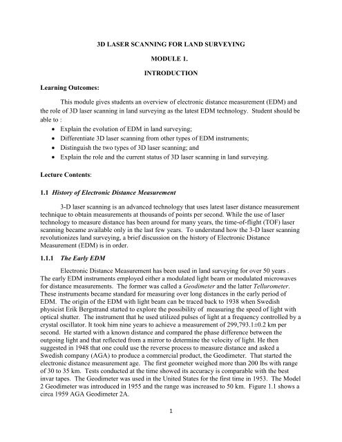
Figure 1.1 A circa 1959 AGA Geodimeter 2A showing the front control panel.(From NOAA 200 Years Celebration Website, Photos courtesy of the University ofNew South Wales School of Surveying and Spatial Information Systems VirtualSurveying Instrument Collection)The first Tellurometer was developed around 1957 in South Africa. Unlike theGeodimeter which used light waves, the Tellurometer used microwave. The range of thisinstrument was 30 to 50 km. Because microwave signals are more affected by manyenvironmental factors such as humidity, powerline, geomagnetic storm, etc., the instrumentsusing microwaves were not as accurate as those using light waves. Figure 1.2 shows aTellurometer.Figure 1.2 A Tellurometer (From NOAA 200 Years Celebration Website, Photoscourtesy of the Alberta Land Surveyor's Association Surveying Instrument Collection)2
1.1.2 The Second Generation EDMGeodimeter evolved quickly through the 1960s. The weight was reduced from 200 lb to20 lb and the measurement time from 45 minutes to 10. The tungsten light bulb was replacedwith a high-pressure mercury vapor lamp in Geodimeter 4D where D stood for day-light in 1963and the first EDM instrument with a laser light source was created when George Lesley of theCoast and Geodetic Survey (C&GS) replaced the mercury vapor lamp in Geodimeter 4D with athree-milliwatt helium-neon gas laser in 1966, opening the age of EDM with laser. Figure 1.3shows a modified Geodimeter with Laser as a light source.With the introduction of semiconductors into electrical circuitry, the design of EDMinstruments was revolutionized. First, the vacuum tubes were replaced with transistors and then,light-emitting photo-diode was invented which significantly reduced the size of the light source.In Geodimeter Model 6 introduced in 1964, vacuum tubes were replaced with transistors,significantly reducing measurement time since the warm-up time for the vacuum tubes waseliminated. Wild DI 10 Distomat was one of the first EDMFigure 1.3 The "Big Red", a modified Geodimeter with Laser. Clockwise from top left:Control panel; optics; set up showing separate power packs for Geodimeter and laser; anda side view of the instrument. (From NOAA 200 Years Celebration Website, Photoscourtesy of Charlie Glover)instruments to use a semiconductor photo-diode as a light source. It used a gallium-arsenidelight-emitting diode and the electromagnetic wave length was in the infrared range. Wild startedto experiment with gallium-arsenide diodes as early as 1963. Power consumption of these diodeswas very low and their electromagnetic waves can be directly modulated in intensity. By the endof 1966, Wild, in collaboration with another organization (SERCEL), had produced a prototype3
as a carrier signal, a digital theodlite, a microprocessor and a data collector. These instrumentscan automatically observe both angle and distance, calculate the coordinates and store data. Mostof the EDM systems used in these TS instruments are based on the phase-shift distancedetermination principle. In this method, a light beam emitted by a diode is splited into anexternal beam which bounces back from the target (prism) to be measured and an internalreference beam and, the phase difference between the two is determined. In addition to thephase difference, the number of full cycles that a light wave has undergone must also be knownbefore the full distance can be calculated. The determination of the number of full cycles isreferred to as resolving the cycle ambiguity. Most of these instruments require the use of areflector (prism). EDM reflectors also went through a lot changes over the years. The firstreflector used for the Geodimeter was a flat mirror, then a spherical mirror was used andeventually prisms are adopted. Most reflectors in use today are retro-reflector made of cubecorner prism which is formed by cutting the corners off a glass cube. Figure 1.6 shows amodern prism reflector.Figure 1.5 A Zeiss Elta 46 Total Station. (Photo Courtesy of National Museum ofAmerican History)5
(a)(b)Figure 1.6 Modern Prism Reflectors. (a). SECO 360° Robotic Prism Assembly; (b).SECO Tilting Triple Prism Assembly. (Courtesy of California Surveying/DraftingSupply)In recent years, with the improvement of signal processing technology and precision, theTime-of-Flight (TOF) TS instruments also begin to appear. In these instruments, the EDMsystem generates many short infrared or laser light pulses, which are transmitted through thetelescope to a target. These pulses bounce back from the target and return to the instrument,where the time for the round-trip is determined directly by the system for each light pulse. Withthe velocity of the light through a medium known, the distance between the instrument and targetcan be easily determined. The pulses generated by the TOF instruments can be many times morepowerful than the energy used for a phase-shift instrument, and hence the TOF method canachieve a much longer distance measurement. Taking the Trimble TS as an example, theTrimble DR 300+ with the TOF technology can measure up to 400 meters, reflecting off aconcrete surface while the Trimble DR Standard employing the phase-shift method can onlymeasure up to 100 meters off the same surface. When a reflector (prism) is used, however, theranges for the two instruments are comparable, 5500 m for the DR 300+ and 5000 m for the DRStandard. Because of its long range, the TOF method is preferred over phase-shift forreflectorless measurement. The phase-shift technology did have one advantage over TOF: it canachieve better accuracy. However, with the improvement of signal processing technology inTOF method, the accuracy discrepancy between the two is becoming insignificant in manyapplications. Figure 1.7 shows a Trimble S6 DR Total Station.Figure 1.7 Trimble S6 DR Total Station. (Courtesy of Trimble Navigation Limited)6
1.1.4 GPS (Global Positioning System)GPS measurements are also electronic distance measurement although one usually doesnot use the term EDM to describe them. In GPS, the distances between satellites in space andthe ground receivers are determined using electromagnetic waves in the microwave radiofrequency range. The GPS satellites emit electronic signals with two carrier frequencies: L1,1575.42 MHz and L2, 1227.60 MHz. The carriers are modulated into two codes: P code, with10.23 MHz frequency and C/A code with 1.023 MHz frequency. The distances are determinedwith either the phase-shift method similar to that in EDM or code-ranging method analogous toTOF.The global position system can be divided into three segments based on segmentfunctions: space segment, control segment and user segment. The space segment consists of aconstellation of 24 satellites placed in six orbital planes at 60 degrees apart around the equatorand the planes have an inclination angle of 55 degrees with the equator. This orbital designprovides enough coverage so that a sufficient number of satellites can be tracked at any locationon earth at any time to determine the position of that location. The satellites travel in nearcircularorbit with mean altitude of 10900 nautical miles (20200 km) in a period of 11 hours, 58minutes. They are usually identified by their PRN (Pseudo Random Noise) number or spacevehicle number (SVN).The control segment is composed of five monitoring stations around the globe. They arelocated at Colorado Springs, the Islands of Hawaii, Ascension, Diego Garcia, and Kwajalein.The stations monitor the signals of the satellites, track their orbits and send tracking informationto the main control station in the Consolidated Space Operations Center located at Shriever AirForce base in Colorado Springs. The main station uses the tracking information to calculate theprecise near-future orbits of the satellites and clock correction coefficients, and transmit thesedata back to the satellites via upload stations. The satellites, in turn, broadcast the information aspart of their transmission for use by receivers on the ground to determine positions.The user segment consists of GPS receivers and user community. The receivers receivethe signals from the satellites, determine the distances and convert the distances to positions. Aminimum of four satellites are required to compute the X, Y, and Z coordinates with reasonableaccuracy. Receivers range in capability from high-end survey level receiver with mm accuracy tomapping and GIS types of receiver with submeter accuracy, to marine navigation receiver and tovehicle tracking system (
(a)(b)Figure 1.8 GPS user segment equipments. (a) Trimble 5800 receiver; (b) the antenna fora Trimble 5700 receiver.1.1.5 Terrestrial 3-D Laser ScannersTo date, all the Total Station instruments are designed to measure one point at a time.The user would aim the telescope at the prism and put a button to measure the distance. It takestime to setup, aim and shoot. Even the latest robotic TS with automatic tracking takes 1 to 5seconds to measure a distance. GPS measurements were also conducted at one position at a time.In contrast, the 3-D laser scanner can measure 5000 distances per second, thousands of timesmore efficient than a TS. The improvement in productivity and the benefits to the surveyingindustry are very obvious.Currently, most 3-D laser scanners employ the TOF method. Unlike in a TOF TotalStation where the laser pulses are aimed at one point and the resulting distances averaged, thelaser pulses in a 3-D laser scanner are deflected to different targets by rotating or oscillatingmirrors inside the instrument or by rotating the instrument itself. Some instruments deploy twodeflection mirrors, one for the vertical view field and the other for the horizontal view field.Others use one deflector for the vertical view field and the horizontal view field is accessed byrotating the instrument horizontally. These systems can acquire a few thousand points persecond with a range of a 200 to 300 m and an accuracy of a few mm for a distance of 100 m.The horizontal view field for most scanners is 360 o and the vertical view field ranges from 60 o to320 o . Sophisticated field software are used to setup the system, gather data (called "pointclouds") and transfer data between field devices and office computer. In addition, postprocessingis a major part of the 3-D laser scanning technology. Post-processing software allowmultiple point-cloud registration; data filtering and checking; 3-D modeling; digital imagecalibration; multi-ortho projection; contour, cross-section and profile generation; volume andsurface calculations; feature code management; and other functions.8
(a)(b)Figure 1.10 3-D laser scanners. (a) Trimble GX <strong>3D</strong> scanner; (b) Leica ScanStation.(Courtesy of Trimble Navigation Limited and Leica Geosystem.)1.1.6 Airborne Laser Scanning System (Lidar)The airbone laser scanning system, alternatively referred as Lidar (Light Detecting andRanging), uses the same principles as 3-D laser scanners. The system usually is mounted on anairplane or helicopter. The scanned distances are relative to the position of the airplane. Toobtain the absolute position of a point on the ground, a system that tracks the position of theairplane itself must be installed on the airplane. This system usual is a GPS unit in combinationof an INS (Inertia Navigation System). Airborne laser scanning system has a longer history thanthe terrestrial 3-D laser scanning system. NASA started to experiment with Lidar in the 1970's,but it is not until the 1990's when the first commercial unit became available. Figure 1.11 showsNASA's Harlie airborne lidar system.Figure 1.11 NASA's Harlie Holographic Airborne Rotating Lidar . Left: transceiver(scanning system) and Right: electronics rack. (Courtesy of NASA)9
1.2 3-D Laser Scanning Applications in Land SurveyingAs mentioned earlier, 3-D laser scanners can be thousands of times more efficient thantraditional TS instruments and GPS in acquiring positional data. Because of this, the surveyingindustry is quickly adopting this technology. Currently the terrestrial 3-D laser scanner market isgrowing at a rate of 35-40% annually.In general, the application of 3-D laser scanning is most beneficial in two situations: a)the points to be surveyed are dense, and b) the area to be surveyed is not accessible. Here aresome specific applications:Topographical surveying or mapping surveying. The results from this type of surveyingare used to create contour maps for engineering design or other purposes. It generallyrequires a lot of points to be surveyed, especially for large scale maps such as those usedin land development. Using conventional methods or GPS, each point must be surveyedindividually and the process is very time-consuming. With 3-D laser scanning, thesurveying time can be reduced dramatically.As-built surveying. Surveys are conducted periodically in large construction project tocheck progress for payments to contractor and for compliance with design plans and todocument the project when it is complete. This type of surveying requires a lot of detailsand may interrupt normal construction activities and endanger the instrument operator ifconventional surveying methods are used. In some case, the targets may not beaccessible, a bridge pier in a deep river, for example.Facility improvement. Whether one tries to add an annex to an existing building or reroutethe pipelines in a chemical plant, the engineers must obtain the existing detailsbefore they can start the new design. Capturing all the details would be a timeconsumingprocess with conventional surveying method. 3-D laser scanning can shortenthe working schedule considerably.3-D imaging. The point clouds captured by a 3-D scanner can be used to construct 3-Dvector images which can be readily incorporated into a CAD model created by theengineers for engineering design and modeling. In contrast, the images created by adigital camera are two-dimensional and in raster format which cannot be easilyincorporated into CAD models. The applications of 3-D laser scanner in 3-D imaging arenot limited to land surveying, and known applications include forensic investigations,environmental protection and restoration, historical preservations, architectural designand reverse engineering.1.3 Economic Impacts of 3-D Laser Scanning Applications in Land SurveyingTerrestrial 3-D laser scanning for land surveying is still at its early stage and has thepotential of reducing surveying cost significantly. Tom Greaves of Sparc Point Research, LLC,an organization specializing in research on 3-D laser scanning applications, discussed theeconomic benefits of using 3-D laser scanning from four different areas:1. Direct cost savings in comparison with conventional survey methods. Base on anecdotalevidences, he estimated that direct cost savings from using 3-D laser scanning are on the10
order of 10 to 20%. In cases where access is difficult, the savings can be much higher.He stated that the time taken to collect data can be reduced from weeks to days by using3-D laser scanning.2. Construction savings. Greaves used documented and validated examples to show that byusing laser scanning, a construction project can save 5 to 10% of the total cost. Thesavings mainly come from construction schedule reductions, reduced errors and rework.He estimated that there is a $2.2 billion potential savings in U. S. non-residentialconstruction sector by adoption of 3-D laser scanning.3. Asset operation and maintenance benefit. Here again, 3-D laser scanning reducemaintenance and repair costs through capturing the existing condition and providing 3-Ddata for retro-fitting and repair design.4. Safety dividend. In economic analysis, it is hard to put a dollar figure on the value ofimproved safety. However, it is one of the forces driving the adoption of laser scanningtechnology. Using 3-D scanning means that surveyors do not have to go to dangerouslocations such as a fast-moving traffic lane, a cliff or under a construction crane.11
Questions1. What is the difference between a Geodimeter and Tellurometer?2. What kind of distance measurement principle are most total stations based on?3. What kind of the distance measurement principle is <strong>3D</strong> laser scanning based on?4. What are the two types of <strong>3D</strong> laser scanning in land surveying?5. List three applications in which using <strong>3D</strong> laser scanning is advantageous.6. Conduct an internet search and write a report on the history of electronic distancemeasurement.7. Conduct an Internet search and write a summary on the current status of <strong>3D</strong> laserscanning applications in surveying industry.12
Laboratory and Field ActivitiesThis lab will familiarize the students about the <strong>3D</strong> laser scanning equipment and fieldsetup. Topics include:Laser safetyScanner componentsControl and data collection unitAccessoriesEquipment setupTrimble GX <strong>3D</strong> ScannerTrimble GX <strong>3D</strong> scanner is based on the time-of-flight measurement principle. Advancedelectronics are used to compute the distance to the target and the distance is combined with angleencoder measurements to provide <strong>3D</strong> position of a point. Some of the features of the GX <strong>3D</strong>scanner include:Measurement range: 155 m (18% reflectance) to 350 m (90% reflectance);Single point accuracy: 7 mm at 100 m for distance and 12 mm at 100 m for position.Scanning speed: up to 5000 points/sec.;Fully operational under all light conditions; andField software for scanning control and data recording.Now, let's look at the details of scanner.The front viewThe front view of the scanner is quite straight-forward. It has a glass window, plasticwindow cover to protect the glass, a handle for grasping the instrument and a laser warning labelas a safety reminder. The studs (3 of them) which are inserted in the tribrach during setup canalso be seen from the front.13
Figure L1-1. Front view of Trimble GX <strong>3D</strong> laser scanner.The Back viewThe back view show all the connection ports and indicator lights as well as anotherhandle and warning label. The ports are:Ethernet connection port – for connection with the notebook computer24V power connection port – for connection to the batteries or power adapterUSB port – data transfer extension such as wireless devicesThe indicator lights are as follows:Power – a green light. It is off when the power is not on, flashes during setup andstay on when the scanner is working.Comm – an orange light. It flashes when the scanner is communicating with thecomputer or data collector.Laser – a red light. It illuminates when the laser is ON.14
Figure L1-2. Back view of the Trimble GX <strong>3D</strong> laser scanner.The right viewHeat exchange (radiator) - for coolingAir outlet – for ventilationCenter instrument height measurement mark – for slope distance measurementfrom the ground mark to the center of the scannerBottom instrument height measurement mark – for slope distance measurementfrom the ground mark to the bottom of the scanner15
Figure L1-3. Side view of Trimble GX <strong>3D</strong> laser scanner.mark.The left view is similar to the right view except that there is no bottom measurementThe Top and Bottom Viewstarget.The top view shows a hole with thread which can be used to attach an aiming rod orThe bottom view shows the studs that can be inserted into the tribrach for attaching thescanner to the tripod.16
Figure L1-4. Bottom view of Trimble GX <strong>3D</strong> laser scanner.Figure L1-5. Top view of Trimble GX <strong>3D</strong> laser scanner.17
Control and Data Collection UnitThe control and data collection unit of a Trimble GX <strong>3D</strong> scanner can be a notebookcomputer or a traditional Trimble surveying controller such as Trimble Recon or TSC2. Thiscourse mainly concentrates on using the notebook computer as a control and data collection unit.The field software running on a computer is called PointScape and that for the controllers thePocketScape.To run the PointScape field software, a notebook should have the following features;Processor : fastest available (min. 2GHz)Ram: 2 GB (min. 1 GB)Graphics card: latest available (min. 128 MHz)Operation system: Window 2000 Pro, Window XPMouse: three buttons with wheelPower Supply AccessoriesAccessoriesTrimble GX <strong>3D</strong> scanner can be powered by an AC adaptor or batteries supplied byTrimble. The AC adapter’s input voltage is 90 -240 V and output voltage is 24 V, the powersupply voltage of the scanner. The Trimble scanner battery kit includes the following:Figure L1-6. Batteries connected with power supply cable.18
Two 12V NiCd/NiMh batteries with 18AhTwo chargers with 100-240V input and 6-12V output. The charger’s indicating light isyellow initially, orange when charging and green when top-off. The battery chargingtakes about 14 hours.Power supply cable which has one connector to be attached to the scanner power supplyport and two at the other end, one for each battery.Tribrach With Optical PlummetThe Tribrach is the same piece of equipment used in traditional surveying for attaching aninstrument to the tripod. The components are:Figure L1-7. Tribrach with optical plummet.Foot screw (x3) – for leveling the instrument;Holes (x3) – for holding the studs of the instrument;Circular bubble – leveling indicator, the bubble is centered when the instrument isleveled;Clamping lever – for locking the instrument on the tribrach; andOptical plummet eyepiece – for vertically aligning the instrument with the ground mark.19
Ethernet CableTrimble also supplies an Ethernet cable for broadband connection between the notebookcomputer and the scanner. The cable is a regular cable with nut at one end to be screwedonto the thread of the scanner Ethernet connection port.Figure L1-8. Ethernet cable.Laser SafetySafety is an important issue in lab and field operations. Trimble GX and GS Series laserscanners comply with the performance requirements of US FDA 21 CFR §1040.10 as a CLASS2 <strong>LASER</strong> PRODUCT. Class 2 lasers emit visible (400 to 700nm) output below 1mW. They emitlight that poses very little risk to the human eye. The eye’s natural aversion response to brightlight prevents injury to the eye. However, these lasers do pose a dazzle hazard.The Trimble GX and GS Series laser scanners also comply with the performancerequirements of IEC 60825-1 as a CLASS 3R <strong>LASER</strong> PRODUCT. Class 3R lasers emitbetween 1 and 5mW of output power. IEC (International Electrotechnical Commission) reservesthe 3R classification for those laser products that yield output of up to a factor of five over themaximum allowed for Class 2 in the 400 to 700nm wavelength range and up to a factor of fiveover the maximum allowed for Class 1 for other wavelengths. Designation “R” indicates reducedrequirements,” requirements that are less stringent than those reserved for 3B lasers. The risk ofinjury from directly viewing a Class 3R laser beam remains relatively low, but users should takegreater care to avoid direct eye exposure, especially when handling invisible output. Although20
the laser used in the Trimble GX <strong>3D</strong> laser scanner poses low risk to the eyes, the operatorsshould take the following precautions:Do not look directly into the beam with or without an optical instrument.Keep out of the scanning zone [remain behind the scanner].Keep other people present behind the scanner and away from the scanning zone.Do not look at the scanner window during scanning.Work preferably under normal lightning so that the eye pupil is kept small [2 mmtypically], thereby minimizing the laser power that can reach the retina.The laser beam should be terminated at the end of its useful beam path. Scanner pilotsoftware may include settings to limit beam distance.The laser beam should be located well above or below the eye wherever practicable.Precautions should be taken to ensure that the laser beam is not aimed unintentionally atmirror like surfaces.When not in use the laser instrument should be stored in a location where unauthorizedpersonnel cannot gain access.Lab ReportDiscuss the components of the <strong>3D</strong> laser scanner and accessories, and safety precautionsto be taken when operating <strong>3D</strong> laser scanner.21