ELECTRONIC POWER FACTOR REGULATOR type EMR ...
ELECTRONIC POWER FACTOR REGULATOR type EMR ...
ELECTRONIC POWER FACTOR REGULATOR type EMR ...
- No tags were found...

Create successful ePaper yourself
Turn your PDF publications into a flip-book with our unique Google optimized e-Paper software.
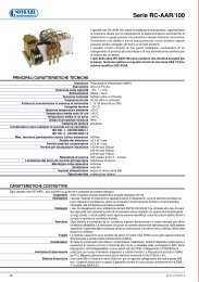
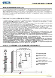
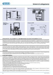
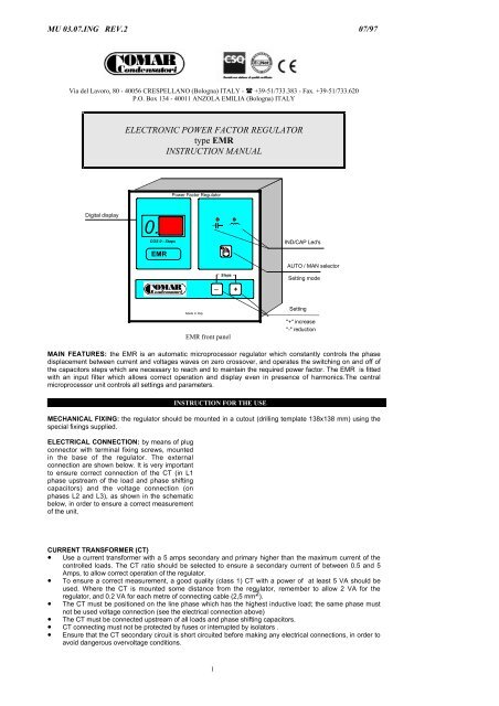
MU 03.07.ING REV.2 07/97Via del Lavoro, 80 - 40056 CRESPELLANO (Bologna) ITALY - ! +39-51/733.383 - Fax. +39-51/733.620P.O. Box 134 - 40011 ANZOLA EMILIA (Bologna) ITALY<strong>ELECTRONIC</strong> <strong>POWER</strong> <strong>FACTOR</strong> <strong>REGULATOR</strong><strong>type</strong> <strong>EMR</strong>INSTRUCTION MANUALPower Factor RegulatorDigital display0.COS 0 - Steps<strong>EMR</strong>IND/CAP Led'sAUTO / MAN selector_Steps+Setting modeMade in Italy<strong>EMR</strong> front panelSetting"+" increase"-" reductionMAIN FEATURES: the <strong>EMR</strong> is an automatic microprocessor regulator which constantly controls the phasedisplacement between current and voltages waves on zero crossover, and operates the switching on and off ofthe capacitors steps which are necessary to reach and to maintain the required power factor. The <strong>EMR</strong> is fittedwith an input filter which allows correct operation and display even in presence of harmonics.The centralmicroprocessor unit controls all settings and parameters.INSTRUCTION FOR THE USEMECHANICAL FIXING: the regulator should be mounted in a cutout (drilling template 138x138 mm) using thespecial fixings supplied.ELECTRICAL CONNECTION: by means of plugconnector with terminal fixing screws, mountedin the base of the regulator. The externalconnection are shown below. It is very importantto ensure correct connection of the CT (in L1phase upstream of the load and phase shiftingcapacitors) and the voltage connection (onphases L2 and L3), as shown in the schematicbelow, in order to ensure a correct measurementof the unit.CURRENT TRANSFORMER (CT)• Use a current transformer with a 5 amps secondary and primary higher than the maximum current of thecontrolled loads. The CT ratio should be selected to ensure a secondary current of between 0.5 and 5Amps, to allow correct operation of the regulator.• To ensure a correct measurement, a good quality (class 1) CT with a power of at least 5 VA should beused. Where the CT is mounted some distance from the regulator, remember to allow 2 VA for theregulator, and 0.2 VA for each metre of connecting cable (2,5 mm 2 ).• The CT must be positioned on the line phase which has the highest inductive load; the same phase mustnot be used voltage connection (see the electrical connection above)• The CT must be connected upstream of all loads and phase shifting capacitors.• CT connecting must not be protected by fuses or interrupted by isolators .• Ensure that the CT secondary circuit is short circuited before making any electrical connections, in order toavoid dangerous overvoltage conditions.1
• Wherethe parallel connection of two (or more) loads are being controlled, one CT per load should be used,with a summating CT having a secondary current of 5 amps and a primary current of 5 + 5 Amps. In thesecases, the transformer ratio will be the sum of the individual CT's. Example : nr. 3 x CT 500/5 =1500/5Note. <strong>EMR</strong> regulators are able to detect automatically the current phasing of the CT. It will not be necessary toensure correct polarity connections as with other Power Factor Regulators.<strong>POWER</strong> OF CONTROLLED BANKS: the regulator works according to binary logic sequence; the switching onand off of capacitors banks always start from the first bank.For correct operation of the automatic bank, the power ratio per bank should be:a. equal to each other (1.1.1.1.1.1.1.1)b. double of the previous bank (1.2.4.8.16.32)c. equal or double of the previous bank (1.1.2.2.4.4)NUMBER OF STEPS: is determined by the power combination which has been used on single capacitors bank:Examples: 6 banks in the sequence 1.1.1.1.1.1 make 6 steps6 banks in the sequence 1.1.2.4.4.4 make 16 steps6 banks in the sequence 1.2.4.8.16.32 make 63 stepsNote. Where the step sequence is uneven too high a number of steps will result in a high number of switchingoperations which will considerably reduce the life of the equipment. With the first step too high hunting may occurwhich again would produce excessive wear and reduced life of the components.• NORMALLY 8-16 REGULATIING STEPS IS THE BEST SOLUTION TO ADOPTWORKING SITUATIONThe AUTOMATIC (default condition when switching on the regulator) or MANUAL working condition are optainedby pushing the button .• AUTOMATIC working: this is the standard condition when switching on the regulator. When the networkis inductive (motors, transformers, fluorescent lamps, ecc.), the red led __ _ _ _ is on and the regulator begin toconnect capacitors banks. If too many capacitor banks are connected, the red led –º– will be on and theregulator will begin to switch off banks. The preset PF value will be achieved when both Led's __ _ _ _ and –º–will be off.• MANUAL working: press button . When the regulator is in the manual mode the red Led on thebutton will be on. In manual mode, the regulator will not operate without an external control (both inductive andcapacitive Led's are off). By pressing either the "+" or "-" buttons all banks will be connected or disconnected onestep at a time. Each button must be pressed for at least 25 secs. Operating banks will be shown by the red Led'scorresponding to numbers 1 - 2 - 3 ..... When a power loss occurs, all capacitor banks will be switched offautomatically. When the power returns, the regulator will again insert all banks step by step.SETTINGS ON <strong>REGULATOR</strong>: after making the required connections to the regulator, the following adjustmentsshould be made. Note: In the presence of alarms, the settings mode is forbidden.• C/K settingBy pressing the button for 4 secs in AUTOMATIC mode, the "SETTING MODE" will be entered.The red led –º– will illuminate and, at the same time, a number (0.1_ 0.5) will appear in the digitaldisplay. To release the button and use the " + " or "-" buttons to change the selection. Thesuggested value to set is given on the table "C/K VALUES" (see table on the next page). The numberwill represent the range (positive/negative) of the PF values possible to obtain.• PF settingAfter setting the C/K value, press thebutton again for 4 secs to indicate the selected PF required.At the same the red led’s –º– and __ _ _ _ will illuminate. To release the button and use the " +" or "-" buttons to change the selection. A PF of 0.95 is recommended.Example: setted C/K = "0.2" setted PF = "0.95"The regulator will switch bank to achieve a PF value within 0.93 and 0.97 (0.95 ± 0.02)The “-” led near the two numbers display is illuminate if the P.F. value is more than 1.00.If the P.F. is equal 1.00 the value indicate on two numbers display is “-.00”• FREQUENCY settingAfter setting the P.F. value, press the button again for 4 secs to indicate the selectedFREQUENCY. The red led __ _ _ _ will illuminate and, at the same time, a number (50) will appear inthe digital display. To leave again the60Hz.button and use the " + " or "-" buttons to regulate the valueSAVING THE SET VALUESBy pressing the button the C/K, P.F. values and frequency which have been selected will be saved andthe P.F.Regulator works in AUTOMATIC condition.DIGITAL DISPLAY2
It is possible to read the values of PF and the working banks on the digital display. Starting the P.F. Regulatorindicates the value of P.F. ; to read the number of working banks it need to push at the same time thebuttons “+” and “-”.ALARMS• No Supply voltage alarm: when the voltage supply is lost, the digital display is off.• Min current alarm: when the current on the amperometrical circuit is less than 500mAms, the P.F.Regulator is only able to switch off the capacitor banks if the PF value is more than 1.00. The MANUALfonctioning is possible. Improved the working normal conditions, the P.F. Regulator works normaly. Thealarm causes the visualization of charge state ( __ _ _ _ or –º– ) and “EE” on the display.• Zero current signal (lower than 10 mA): when the current on the amperometrical circuit is less than10mAmps, the P.F. Regulator will only operate in MANUAL mode. The alarm causes the visualization ofcapacitive charge state ( –º– ) and “CA” on the display.• Supply interrupts: to avoid dangerous operating condition on contactors when the supply voltage isinterrupted, the <strong>EMR</strong> switches off all capacitors banks until reconnection. Micro breaks trouble onnetwork must be solved by the client.When alarm condition disappears, the regulator will reset itself automatically.WORKING TROUBLES AND SOLUTIONS: most malfunctions are caused by incorrect connections.TROUBLESOLUTIONAll banks on with a low inductiveload on the networkThe CT is connected upstream the load but not of capacitors.Connect the CT as shown in the connection diagramContinous switching on and off ofone bank (hunting phenomena)a) The C/K value is not correct.Check in the table "C/K VALUES" for the right valueb) The power of the first bank is too high for the selected PFrequirements: reduce the first bank power according toparagraphs "BANKS <strong>POWER</strong>" and "NUMBER OF STEPS"Increase the selected PF valueDisplaied PF values not correct a) CT installed in the wrong phase: connect to phase L1b) Wrong regulation of rated frequencyRead “Settings on regulator”IND and CAP leds off a) Possible stand-by condition: at least one capacitor bank on.Check the PF value of the network on the displayb) Possible MANUAL working conditionChoose the AUTOMATIC operationCAP led is ON without capacitorbanks workinga) Zero current signal: check the C.T. and its connection andensure the minimum secondary current level is least 10mAmps.b) C.T. connected on the supply cable of the PFC equipmentConnect according to electrical scheme at page 2.c) CT installed in the wrong phase : Connect to phase L1Display off, regulator not working a) Check if supply voltage is presentb) Check if supply voltage is equal to the rated voltage of theregulatorDisplay on, banks Led's on butcapacitors not workinga) Check if supply voltage is equal to the rated voltage of theregulatorb) Check the “0” connection on contactorsc) Check if “220V” has been connected on "C" terminald) Check the state of the tree-pole contactorsDisplayed “CA” on display a) Possible capacitive load conditionb) CT installed in the wrong phase : Connect to phase L1c) Zero current alarmDisplayed “EE” on displayMinimum current alarmDisplayed “-00” on display Main P.F. equal 1,00IF PROBLEMS PERSIST AFTER ALL ABOVE MENTIONED SOLUTIONS SWITCH OFF THE <strong>REGULATOR</strong>FOR AT LEAST 20 SECS AND THEN SWITCH ON AGAIN.IF THE PROBLEM IS STILL PRESENT PLEASE CALL OUR TECHNICAL DEPARTMENTTECHNICAL DATARated supply voltage220-230/380-415 V a.c. ± 10% (440 Vac on request)Rated consumption10 VARated supply currentby means of CT secondary side 5A max. (Imin. = 500mA)Current circuit consumption2VARated frequency50Hz - 60HzOutput relays5 A 250 Va.c. resistive loadsMax current on relays common circuit5A at 40°C resistive loadSwitching steps delay 25" (5" on request)Digital dispaytwo numbers displayAlarm delay 10"± 1"Digital displaythree numbers displayRegulator meas. precision :± 2% f.s. on PF measurement (cosØ)Display accuracy :± 2 digitsMechanical dimensions144x144 mm FRONT according to DIN4370085mm. thicknessPlastic caseinsulating self-extinguishing materialCut out dimension138x138 mm. ( tolerance -0mm. /+ 1mm.)3
Weight1,1 KgProtection degreeIP 54 front panel - IP20 rear panelWorking temperature-5°C / + 50°C (indoor service)Relative humidity max. 90% at 20°CAltitude max.2000 metersC/K TABLE for medium current values of 2,5AmpsC/K (d.)First bank power expressed in Kvar (400v)2,5 5 6 10 12,5 20 25 40 50T.A.K30/5 6 0.5 0.5 0.5 - - - - - -50/5 10 0.4 0.3 0.4 0.5 - - - -60/5 12 0.3 0.3 0.4 0.5 0.5 - - - -80/5 16 0.2 0.3 0.3 0.5 0.5 - - - -100/5 20 0.2 0.3 0.3 0.3 0.4 0.5 - - -150/5 30 0.2 0.2 0.3 0.3 0.3 0.5 0.5 - -200/5 40 0.2 0.2 0.2 0.3 0.3 0.3 0.4 0.5 -250/5 50 0.1 0.2 0.2 0.3 0.3 0.3 0.3 0.5 0.5300/5 60 0.1 0.2 0.2 0.2 0.3 0.3 0.3 0.4 0.5400/5 80 0.1 0.2 0.2 0.2 0.2 0.3 0.3 0.3 0.4500/5 100 0.1 0.1 0.2 0.2 0.2 0.3 0.3 0.3 0.3600/5 120 0.1 0.1 0.1 0.2 0.2 0.2 0.3 0.3 0.3800/5 160 0.1 0.1 0.1 0.2 0.2 0.2 0.2 0.3 0.31000/5 200 0.1 0.1 0.1 0.1 0.2 0.2 0.2 0.3 0.31200/5 240 0.1 0.1 0.1 0.1 0.1 0.2 0.2 0.2 0.31500/5 300 0.1 0.1 0.1 0.1 0.1 0.2 0.2 0.2 0.22000/5 400 0.1 0.1 0.1 0.1 0.1 0.1 0.2 0.2 0.22500/5 500 0.1 0.1 0.1 0.1 0.1 0.1 0.1 0.2 0.23000/5 600 0.1 0.1 0.1 0.1 0.1 0.1 0.1 0.2 0.24000/5 800 0.1 0.1 0.1 0.1 0.1 0.1 0.1 0.1 0.2• When the C.T. secondary current signal is lower than 2Amps, the C/K value should be rised of1.• When using the regulator on 220/230Va.c. networks the C/K values should be boubled.• The symbol “-” means that the C.T. is too small in relationship to the power of the first bank.GENERAL INSTRUCTIONRecommendations of the makers associated to the ANIE ( Electrical and ElEctronic Companies National Association)• Read the instructions in this handbook because they furnish important indications about the safety of installation, useand maintenance. Take carefully this handbook for any information.• Check the integrity of the equipment after unpacking it. In case of doubt, don’t use the P.F.Corrector and ask forskilled staff.N.B. If the equipment has fallen or has violenthy shaken during shipping, it could suffer internal damage, which maybe dangerous.• Before connectly the equipment, check the data card; this has to be in conformity with the network ( the alluminiumcard is fixed to the right side of the P.F.Corrector).• This equipment will be assigned only to the use for which it has been specifically made. Each other use has to beconsidered improper and therefore dangerous.• In order for the correct functioning of the equipment the limits of voltage, current and temperature, imposed by theCEI and IEC standards, must never be exceeded.• The equipment has to be protected from atmospheric condition. No <strong>type</strong> of tampering is permitted on the electroniccircuits of P.F.Corrector.• Possible interventions will be performed by COMAR staff.WARRANTYComar Conensatori S.p.A. guaranties own products for twelve months from purchase date. The warranty covers the faultsof materials and manufacture and it has to be understand for goods ex-works. Before the equipment works, allinstructions, present on this handbook, have to be meticulously followed. Breakdowns, caused from imprope use and/ornot conformy to enclosed instructions, and faults, caused from tampering by of not qualified technicians, aren’t covered.The not respect also of a one of the precedent points make to decady the right of warranty.LIABILITYComar Condensatori S.p.A. are not liable for direct or indirect damages consequent the been missing or the wrongoperation.In any case and for any reason COMAR Condensatori S.p.A. can not be considered liable for possible direct or indirectdamages, consequent the malfunctioning of P.F.Corrector, caused from mistakes of assembly or from inadequate use ofthe same.Above data and dimensions are not binding and may be modified without any notice.4
COMAR CONDENSATORI S.p.AVia del Lavoro, 80 - 40056 CRESPELLANO (Bologna) ITALY!+39-51/733.383 - Fax. +39-51/733.620Postal Address: C.P. 134 - 40011 - Anzola Emilia (Bologna) ITALYMU 03.07.ING5