Training Systems for Automation Technology - Lucas-Nülle Lehr
Training Systems for Automation Technology - Lucas-Nülle Lehr
Training Systems for Automation Technology - Lucas-Nülle Lehr
- No tags were found...

Create successful ePaper yourself
Turn your PDF publications into a flip-book with our unique Google optimized e-Paper software.
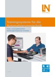
<strong>Training</strong> <strong>Systems</strong><strong>for</strong> <strong>Automation</strong> <strong>Technology</strong>Acquiring Practical Skills andProject-Oriented Expertise
Table fo ContentsQualifications through Quality<strong>Training</strong> <strong>Systems</strong> <strong>for</strong> <strong>Automation</strong> <strong>Technology</strong> .......................................................................................................................... 4Different <strong>Systems</strong> to Fit Differing NeedsOur Objective Is to Meet Everyone’s Standards ........................................................................................................................ 6Presenting Complex <strong>Training</strong> Content in a Vivid WayProject-Oriented <strong>Training</strong> Media – Adaptable to All <strong>Training</strong> <strong>Systems</strong> ..................................................................................... 10The Entire System at a Glance .......................................................................................................................................... 12More than Just a <strong>Training</strong> SystemA Total Solution – the <strong>Automation</strong> Laboratory ...................................................................................................................... 14Instrumentation and Automatic Control <strong>Technology</strong>...................................................................................................... 16Sensor <strong>Technology</strong> in <strong>Automation</strong> ......................................................................................................................................... 18Measurement of Electrical Variables ...................................................................................................................................... 19Measurement of Non-Electrical Variables ............................................................................................................................. 20RLC Measurement ................................................................................................................................................................ 22
Table fo ContentsPractical Introduction to Automatic Control <strong>Technology</strong> ........................................................................................................ 23Analysis of Control Loops ..................................................................................................................................................... 24Design and Optimisation of Controllers ................................................................................................................................ 25Applied Automatic Control <strong>Technology</strong> ................................................................................................................................. 26Automatic Control <strong>Technology</strong> in <strong>Automation</strong> Engineering ................................................................................................... 29Industrial Installation <strong>Technology</strong> .................................................................................................................................... 30Manually Operated Switches in a Three-Phase Circuit ........................................................................................................... 32Contactor Protective Circuits in a Three-Phase Circuit ........................................................................................................... 33Programmable Compact Controls ......................................................................................................................................... 34Electropneumatics in Automated Control ............................................................................................................................. 35Programmable Logic Control ............................................................................................................................................ 36Multimedia-Based <strong>Automation</strong>, PLC and Bus <strong>Technology</strong> ...................................................................................................... 38Programmable Logic Control with SIMATIC S7-300 ............................................................................................................... 40Networked <strong>Systems</strong> in <strong>Automation</strong> Engineering ........................................................................................................... 42AS-Interface ......................................................................................................................................................................... 44PROFIBUS DP ........................................................................................................................................................................ 45Industrial Ethernet/PROFINET ................................................................................................................................................ 46Remote Maintenance and Diagnostics .................................................................................................................................. 47RFID ..................................................................................................................................................................................... 48Image Processing .................................................................................................................................................................. 49Operating and Monitoring .................................................................................................................................................... 50Open-Loop Control of Drive <strong>Systems</strong> .................................................................................................................................... 51Safety <strong>Technology</strong> in <strong>Automation</strong> <strong>Technology</strong> ............................................................................................................... 52Circuitry Involving Safety Relays ............................................................................................................................................ 54AS-i Safety............................................................................................................................................................................. 55PROFIsafe ............................................................................................................................................................................. 56Optical <strong>Systems</strong> .................................................................................................................................................................... 57System Models and Process Simulation ........................................................................................................................... 58Multimedia-Supported Models ............................................................................................................................................. 60PCB Models .......................................................................................................................................................................... 61ProTrain Process Simulation ................................................................................................................................................... 62PLC Universal Process System Simulator ................................................................................................................................ 64Electrical PLC Process System Models .................................................................................................................................... 65“Industrial Mechatronics System” IMS ® ........................................................................................................................... 66Sub-<strong>Systems</strong> at a Glance ....................................................................................................................................................... 68Education towards Industrial Standards ................................................................................................................................ 70Rapid Set-Up and Installation Guaranteed ............................................................................................................................. 71Easy Access to Each Sub-System ........................................................................................................................................... 72IMS ® Conveyor Belt <strong>Systems</strong> and Sub-<strong>Systems</strong> ...................................................................................................................... 74IMS ® Sub-<strong>Systems</strong> ................................................................................................................................................................ 75IMS ® Robot <strong>Technology</strong> ........................................................................................................................................................ 80From IMS ® Sub-<strong>Systems</strong> to IMS ® Production Lines ................................................................................................................ 82IMS ® – Assembly <strong>Technology</strong>.................................................................................................................................................. 85IMS ® - <strong>for</strong> Use with All Process Control <strong>Systems</strong> .................................................................................................................... 86IMS ® Aluminium Profile Trolleys ............................................................................................................................................. 87IMS ® Virtual .......................................................................................................................................................................... 88
Qualifications through Quality<strong>Training</strong> <strong>Systems</strong> <strong>for</strong> <strong>Automation</strong> EngineeringTechnical advances …<strong>Automation</strong> technology is becoming ever more important thanksto the rapid developments taking place in industrial processauto mation. Developments here are very closely integrated intoother related fields such as drive technology, automatic control orcomputer engineering. Due to the lightning fast pace of development,automation engineering has become one of the mostinnovative and rapidly changing fields in electrical engineering.… have an enormous impact on vocationaltraining and educationNew industrial solutions necessitate new training systems. Innovationsin decentralisation and visualisation, the introduction ofthe internationally applicable IEC1 131-3 standard, and thus theuni<strong>for</strong>m PLC programming of controls according to uni<strong>for</strong>m rulesand regulations are just a few examples of the way vocationaltraining is being revolutionised.The need <strong>for</strong> modern, practice-oriented training systems that canconvey state-of-the-art technology and the skills needed to masterthem arises from the demands being made on today‘s auto mationtechnicians.4<strong>Lucas</strong>-<strong>Nülle</strong>
A strong partnership with industryThat is what provides the guarantee <strong>for</strong> a hands-on, practicalapplication. <strong>Lucas</strong>-<strong>Nülle</strong> has found an excellent partner in marketleader Siemens AG. The most modern products to be found inautomation technology have been provided by Siemens AG tobe modified <strong>for</strong> teaching purposes and adapted <strong>for</strong> the preciserequirements of training colleges and educational institutions. Allof the curriculum requirements are covered regardless of the levelof difficulty from the compact basic system version all the wayto modular high-end systems with field bus interface and decentralisedperipherals including operating and monitoring equipment.Safety technology, too, has of course been integrated into all ofthe systems in con<strong>for</strong>mance with the latest European guidelinespertaining to machinery. The modular and scalable training system<strong>for</strong>ms the innovative and future-proof foundation <strong>for</strong> excellent andin-depth training in the area of automation engineering.<strong>Lucas</strong>-<strong>Nülle</strong>5
Different <strong>Systems</strong> to Fit Differing NeedsOur Objective Is to Meet Everyone’s StandardsUniTrain-IWith the multimedia-based experiment and training system UniTrain-I, students are guided through the individual experiment stepsof a well-structured and educationally designed course assisted by texts, graphics, animations and tests.In addition to the training software, each course contains an experiment card that allows the practice-oriented assignments to beper<strong>for</strong>med. Courses on automation engineering convey the knowledge and skills needed to understand the control, operation andmaintenance of modern process automation systems. In these various courses, animations and numerous experiments on authenticsystems assist the students in working their way through the fundamentals, principles and component features of automated processesand manufacturing systems.Your benefits• Theory and practice at the same time and the same place• High student motivation induced by PC support and newmedia• Rapid learning success thanks to well-structured coursedesign• Rapid comprehension of theory thanks to animation andgraphics• Technical skills trained with autonomous experimenting• Constant feedback provided by comprehension questionsand tests• Guided trouble-shooting using integrated fault simulator• Guaranteed safety thanks to extra-low safety voltage• Huge selection of courses (courses on more than 100 topicsavailable)• Sample solutions <strong>for</strong> trainers6<strong>Lucas</strong>-<strong>Nülle</strong>
UniTrain-I system• Comprehensive portablelaboratory• Multimedia courses• High-tech measurement andcontrol interface• Theory and practicein conjunctionUniTrain-I interface withUSB interface• Oscilloscope with 2 analoguedifferential inputs• Sampling rate 40 Msamples/s• 9 measuring ranges100 mV - 50 V• 22 time ranges 1 μs - 10 s• 16 digital inputs/outputs• Function generator <strong>for</strong> frequenciesup to 1 MHz• 8 relays <strong>for</strong> fault simulationUniTrain-I experimenter• Accommodates experimentcards• Experiment voltage supply± 15 V, 400 mA• Experiment voltage supply5 V, 1 A• Variable DC or three-phasesource 0 ... 20 V, 1 A• IrDa interface <strong>for</strong> multimeter• Additional serial interface <strong>for</strong>cardsIntegrated measuring equipmentand power supplies• Multimeter, ammeters,voltmeters• Dual-channel storage oscilloscope• Function generator and wave<strong>for</strong>mgenerator• PROFIBUS monitor• PROFIBUS tester• ... and many other instrumentsLabSoft training andexperiment software• Huge selection of courses• Comprehensive theory• Animations• Interactive experiments withinstructions• Free navigation• Documentation of experimentresults• Tests<strong>Lucas</strong>-<strong>Nülle</strong>7
Different <strong>Systems</strong> to Fit Differing Needs<strong>Training</strong> panel systemWhether it be <strong>for</strong> conventional classroom instruction or practice-oriented student experiments, the training panel system allowsteachers to employ a variety of instructional methods. The training panels consist of moulded panels, both sides of which are melamineresin painted in a dark anthracite colour. All panels are to uni<strong>for</strong>m DIN A4 dimensions.Panel systemYour benefits• Multifaceted and flexible thanks to modular design• Suitable <strong>for</strong> student exercises and demonstration• Safe thanks to double insulation (safety sockets and safety cables)• Integration of industrial components makes systems similar to industrial use• Clear and legible front panel thanks to contrast-rich and scratch-proof printing process• Modern instrumentation with PC connection• Colourful experiment and technical training handbooks• Student worksheets and sample solutions8<strong>Lucas</strong>-<strong>Nülle</strong>
Assembly and installation exercise systemThe perfect compliment <strong>for</strong> project-oriented instructionWhen it comes to installation and assembly exercises it is the technical skills and workmanship that count. All of these exercises arehighly hands-on and practice-oriented. The connections are carried out using industrial methods and wiring materials (mounting rails,terminal strips, screws etc.). All parts except <strong>for</strong> disposable components (such as leads) are reusable.Assembly and installation exercisesYour benefits• Plan and implement projects• Learn connection techniques• High degree of practical experience using industrial-type technical documentationand software• Combinable with the training panel system• Circuitry is implemented using industrial components• Complete project documentation<strong>Lucas</strong>-<strong>Nülle</strong>9
Presenting Complex <strong>Training</strong> Contentin a Vivid WayProject-Oriented <strong>Training</strong> Media – Adaptable to All <strong>Training</strong> <strong>Systems</strong>ManualsThese provide not only the detailed descriptions needed to setup the respective training systems but also numerous exercises,examples and projects.Multimedia coursesMany of the manuals are available in the <strong>for</strong>m of multimediacourses. They contain features familiar from the UniTrain-Icourses, such as:• Test questions• Interactive experiment set-ups• Navigation bars• Animated theory10<strong>Lucas</strong>-<strong>Nülle</strong>
QuickChartsThese provide a quick overview of a certain subject or trainingarea. Work steps, work processes and technical contexts areexplained clearly and concisely.Presentation transparenciesThese support your lessons with, <strong>for</strong> example, background in<strong>for</strong>mation,block circuit diagrams, basic physics, specific standardparameters, special modifications and applications. Supplied as aCD with a set of transparencies in PowerPoint <strong>for</strong>mat.<strong>Lucas</strong>-<strong>Nülle</strong>11
The Entire System at a GlanceSafety technologyin automation engineering CSY 1Circuitswith control relayCSY 2AS-Interfacewith safety motorCSY 3Fail-safe PLCPROFIsafeNetworking, operating and monitoringof automation systemsCAS 1AS-InterfaceCDP 1PROFIBUS DP“Industrial Mechatronics System” IMS ®UniTrain-I multimedia courseMechatronics with IMS ® conveyor belt and sub-systemsProcess simulatorsProcess system modelsPlant modelsCLC 33PLC circuit board modelsCLC 34PLC universal plant simulatorProgrammable logic controlsUniTrain-I multimedia course<strong>Automation</strong> engineering (PLC + bus technology)Industrial installation technologyUniTrain-I multimedia course<strong>Automation</strong> engineering (Electropneumatics)Instrumentation andAutomatic Control <strong>Technology</strong>UniTrain-I multimedia courseSensors, instrumentation, automatic control technology12<strong>Lucas</strong>-<strong>Nülle</strong>
CSY 4/5Application ofoptical systemsCPN 1/2Industrial Ethernet/PROFINETCFW 1Remote maintenanceCCS 2Operation and monitoringCLP 20Open-loop control of electrical drivesIMS ® 1-11IMS ®Conveyor belt and sub-systemsIMS ® 2nFlexible mechatronicssystem (FMS)CLC 35Process simulationProTrain <strong>for</strong> WindowsCLC 40Electrical PLC process modelsCLC 36Automatic control technologyin automation engineeringCLC 30SIMATIC S7-300pre-configured basic setCLC 30SIMATIC S7-300modular assemblyEST 1Manual switchingEST 2Contactor circuitsEST 4Programmable compact control LOGO!IACApplied control technology –automatic flow-rate and liquid-level controlEPEApplied automatic control technology –closed-loop drive control<strong>Lucas</strong>-<strong>Nülle</strong>13
More than Just a <strong>Training</strong> SystemA Total Solution – the <strong>Automation</strong> LaboratoryPresenting complex training content in a vivid wayusing modern training mediaSimple introductionto each IMS ® sub-systemusing multimediaUniTrain-I coursesFlexible production systems with IMS ®14<strong>Lucas</strong>-<strong>Nülle</strong>
Complete solutions <strong>for</strong> process control systems:PLC, AS-i, PROFIBUS, PROFINET, HMI, remote maintenance,safety technology, drive technologyThe system models and process simulatorsoffer a multitude of control assignmentsWith UniTrain-I, multimedia is usedto develop know-how and skills<strong>Lucas</strong>-<strong>Nülle</strong>15
Instrumentation and Automatic Control <strong>Technology</strong>Instrumentation andAutomatic Control <strong>Technology</strong>InstrumentationThe measurement of analog, non-electrical variables is of critical importance and is basic to all areas of automation engineering.After all, it is the detection of the physical variable and its conversion into electrical signals which makes the automatic control of asystem possible in the first place.Automatic Control <strong>Technology</strong>Using the automatic control technology training system, the student is not only introduced to the basics but also gains insight intomore advanced areas in a graphic and practice-oriented way. In the process, modern training systems, such as digitally operatingcon trollers and multimedia-based training systems, are used to convey practical skills and competence to the trainees.16<strong>Lucas</strong>-<strong>Nülle</strong>
Instrumentation and Automatic Control <strong>Technology</strong>Sensor technology<strong>Automation</strong> and closed-loop control technology is based on thedetection of the physical operating states of a process and thevariables which have an effect on it. This is per<strong>for</strong>med by a widerange of sensors that operate according to different physicalprinciples. For that reason, knowledge of sensor technology isindispensable <strong>for</strong> anyone who has anything to do with automationor automatic control technology, and that means themechatronics specialists, too.Closed-loop control technology in automationClosed-loop control technology is of paramount significance <strong>for</strong>modern technical systems. Optimised control loops assist in productionand process engineering, in order to efficiently exploitresources such as energy and raw materials and to ensure pro ductquality. Furthermore, by integrating closed-loop control technologyit is possible to develop innovative and intelligent products,a pre requisite to global competitiveness.Source: Thyssen Krupp<strong>Training</strong> systemsOur training systems cover the following subjects:• Sensor technology• Instrumentation• Automatic control technology<strong>Lucas</strong>-<strong>Nülle</strong>17
Instrumentation and Automatic Control <strong>Technology</strong>Sensor <strong>Technology</strong> in <strong>Automation</strong>Industrial SensorsSensors are needed <strong>for</strong> the open-loop control of technical processes using programmable controllers. They convert physical variablesinto electrical output signals and assume the function of the human senses. As such, sensor technology is fundamental to this fieldand indispensable <strong>for</strong> any automation technician.UniTrain-I course ”Sensor technology in automation“<strong>Training</strong> contents• Working with capacitive and inductive proximity switches• Working with various types of sensors such as magnetic field or optical sensors• Exploring which sensor responds to which material• Determining the switching gap, hysteresis and operating frequency• Methods of testing various materials using sensors driven electrically along the X-axis18UniTrain-I sensor technology in automation equipment set<strong>Lucas</strong>-<strong>Nülle</strong>
Instrumentation and Automatic Control <strong>Technology</strong>Measurement of Electrical VariablesCurrent/Voltage – Power – Work – FrequencyThe introduction to electrical measurement techniques is based on moving-iron and moving-coil galvanometers. Here the instrumentsare used to measure voltages and currents, to work out the effect of the characteristic response on the measurement result,and to expand the measurement range using additional resistors.UniTrain-I course ”Measurement of electrical variables“<strong>Training</strong> contents• Power measurement• Elaboration of measurement principles using DC circuits• Working through the differences between active, apparent and reactive power measurementin simple experiments on an AC circuit• Measurement and explanation of power factor• Load measurements and measurement of electrical work with the aid of a Ferraris meterUniTrain-I measurement of electrical variables equipment set<strong>Lucas</strong>-<strong>Nülle</strong>19
Instrumentation and Automatic Control <strong>Technology</strong>Measurement of Non-Electrical VariablesTemperature – Pressure – Force – TorqueIn modern day industrial practice it is becoming more and more a necessary to monitor, display or electronically process physicalvariables. To do this, you have to use the appropriate tools to convert non-electrical variables into electrical ones.UniTrain-I course ”Measurement of non-electrical variables TPF“<strong>Training</strong> contents• Elaboration of the influence of measurement circuits• Characteristics of different temperature sensors: NTC, Pt 100, KTY, thermocouples• Pressure measurement: piezo-electric, inductive and resistive pressure sensors• Principle of <strong>for</strong>ce measurement with strain gauges applied to bending bars and torsion rods• Recording characteristics <strong>for</strong> different sensors• Methods <strong>for</strong> linearising non-linear characteristics• Identifying possible fault sources20UniTrain-I measurement of non-electrical variables TPF equipment set<strong>Lucas</strong>-<strong>Nülle</strong>
Instrumentation and Automatic Control <strong>Technology</strong>Measurement of Non-Electrical VariablesDisplacement – Angle – SpeedIn mechatronics or drive-technology applications found in manufacturing, the rapid and precise detection of such variables asdisplacement, angle and speed are critical <strong>for</strong> the system‘s dynamic response, efficiency and quality.UniTrain-I course ”Measurement of non-electrical variables sαn“<strong>Training</strong> contents• Analog and digital methods used <strong>for</strong> displacement, angle and speed measurement• Introduction to the required sensors, their operation and characteristics• Experiment-based determination of characteristics• Calibration and measurement circuitry• Experiments with capacitive and inductive-type sensors• Use of optical sensors and Hall sensors <strong>for</strong> detecting the position of rotating shafts• Per<strong>for</strong>ming incremental, BCD and Gray code encoder displacement measurement• Per<strong>for</strong>ming investigations on rotating shafts using a resolverUniTrain-I measurement of non-electrical variables sαn equipment set<strong>Lucas</strong>-<strong>Nülle</strong>21
Instrumentation and Automatic Control <strong>Technology</strong>RLC MeasurementResistance – Inductance – CapacitanceBridge and impedance measurement methods have been used <strong>for</strong> years in bridge measurement circuits to determine the parametersof passive components such as resistors, capacitors and inductors.UniTrain-I course ”RLC measurement“<strong>Training</strong> contents• RLC measurement is per<strong>for</strong>med using calibrated examples of the following:- Wheatstone bridge- Maxwell-Wien bridge- Wien bridge• Elaboration of measurement principles• Measurement with an RLC meter• Comparison of measurement results22UniTrain-I equipment set <strong>for</strong> RLC measurement<strong>Lucas</strong>-<strong>Nülle</strong>
Practical Introductionto Automatic Control <strong>Technology</strong>Instrumentation and Automatic Control <strong>Technology</strong>Closed-Loop Temperature – Speed – Light – Flow-Rate ControlIn the age of automation, automatic control technology is of paramount importance in modern technical systems.UniTrain-I course ”Practical introduction to automatic control technology“<strong>Training</strong> contents• Operating principles of open-loop and closed-loop control• Design and operation of continuous and discontinuous controllers• Hands-on investigation of control loops with continuous controllers• Automatic temperature control of a sauna with 2-position controller• Design and optimisation of an automatic speed control with continuous controllers• Control response to set-point changes and disturbance response of a light control loop• Automatic flow-rate control with 2-position controller and PI controller(requires optional ”liquid-level“ controlled system model)UniTrain-I practical introduction to automatic control technology equipment set<strong>Lucas</strong>-<strong>Nülle</strong>23
Instrumentation and Automatic Control <strong>Technology</strong>Analysis of Control LoopsControl Loop Elements – Continuous Controllers – Discontinuous Controllers– Closed Control LoopsA basic understanding <strong>for</strong> the operational response of different controller types and controlled systems in the time and frequencydomains is decisive <strong>for</strong> selecting the right controller and getting reliable control loop operation.UniTrain-I course Kurs ”Analysis ”Analyse of von control Regelkreise loops“<strong>Training</strong> contents• Recording the step responses to determine the responseand characteristic values of various control loop elementssuch as:- P-action elements- I-action elements- Two PT1 elements- Non-linear elements- Arithmetic elements• Exploring appropriate controller types• Optimising closed control loops• Analysis of control loops and controlled systems usingBode diagrams• Static and dynamic responses of control loop elementsand closed control loops24UniTrain-I analysis of control loops equipment set<strong>Lucas</strong>-<strong>Nülle</strong>
Instrumentation and Automatic Control <strong>Technology</strong>Design and Optimisation of ControllersReal Controlled <strong>Systems</strong> – Optimisation Guidelines – Controller Optimisation– Stability Analysis – Numerical and Fuzzy ControlThese equipment sets supplementary to the ”Analysis of control loops“ course using real controlled systems provide graphic andmore advanced, in-depth understanding of automatic control technology.Fuzzy control is needed to regulate complex measurement variables and non-linear systems. Such fuzzy systems can be integratedinto the automatic control components of the UniTrain-I system by adding a supplementary software package.UniTrain-I UniTrain-I course “Design Kurs ”Reglerentwurf and Optimisation und of Optimierung“Controllers“<strong>Training</strong> contents• Determine the parameters of real controlled systems:- Temperature-controlled systems- Speed-controlled systems- Light-controlled systems• Observe system response with continuous anddiscontinuous controllers in a closed control loop• Investigate the control response to set-point changeand disturbance variables• Per<strong>for</strong>m design and optimisation in the time andfrequency domains• Assessment of control quality and stability analysis in thefrequency domain by plotting a Bode diagram, i.e. locuscurve• Numerical and fuzzy control:- Simulation of control loops on a PC- Real-time control using a PC- Investigation of a fuzzy controller- Automatic fuzzy control of real controlled systemsUniTrain-I design and optimisation of controllers equipment set<strong>Lucas</strong>-<strong>Nülle</strong>25
Instrumentation and Automatic Control <strong>Technology</strong>Applied Automatic Control <strong>Technology</strong>Closed-Loop Liquid-Level Control – Flow-Rate ControlThe ”Automatic liquid-level control“ system is an applied control technology experiment designed specifically <strong>for</strong> training and reallifeapplications. The compact training unit contains a liquid reservoir, a pressure transducer to detect the actual liquid level as well asa reserve tank including pump. To achieve constant pumping power, a secondary control loop with a flow-rate meter is integrated,although it can also be disconnected. Disturbance variables can be simulated using adjustable throttle valves, which modify the inletand outlet flows at the liquid reservoir. As an option, a second liquid reservoir can be included to assemble a controlled system withtime delays of the second-order time delays.Experiment example ”Automatic liquid-level control IAC 10“<strong>Training</strong> contents• Parameters of controlled system• Design and function of closed control loop• Two-position controller in an integral-action controlled system• Two-position controller in a controlled system with higher order time delay• Automatic liquid level-control with continuously operating PI/PID controller• Automatic liquid level-control with secondary flow-rate control loop• Automatic liquid level-control in a system with higher order time delay• Disturbance response of control loop26IAC 10 equipment set<strong>Lucas</strong>-<strong>Nülle</strong>
Instrumentation and Automatic Control <strong>Technology</strong>Digital Universal ControllerAs we have already seen in industry, conventional analog controllers are now being replaced by digital controllers, even in the areasof training and education. Besides the enhanced precision and the ease with which parameters can be set, digital controllers alsooffer excellent capacity <strong>for</strong> being integrated into the process control and process visualisation level via communications interfacesor bus technology. The digital universal controller combines the functionality of an industrial-type digital controller with capacity <strong>for</strong>integration into an educationally designed and proven training system covering the entire field of automatic control technology. Thetraining system is supplemented by specially designed overlay masks, used to conceal all but the functions required <strong>for</strong> the applicationin question, as well as software packages <strong>for</strong> the optimisation of the control loops using the PC.Digital universal controller with overlay masksSoftware packages• Software <strong>for</strong> the investigation of controllers• Software <strong>for</strong> two-position controllers• Software <strong>for</strong> three-position controllers• Software <strong>for</strong> PID controllers• Software <strong>for</strong> four-quadrant drive controllersIAC equipment set<strong>Lucas</strong>-<strong>Nülle</strong>27
Instrumentation and Automatic Control <strong>Technology</strong>Applied Automatic Control <strong>Technology</strong>Static Converters with DC MotorsThe static converter equipment sets can be expanded into converter drives at minimum added cost simply by adding the correspondingelectrical machine. The digital controller then trans<strong>for</strong>ms this assembly into an automatically controlled drive. To investigate thedrive under load in four-quadrant operation mode all you need is a servo brake.Experiment example ”Closed-loop speed control of a DC motor EPE 11“<strong>Training</strong> contents• Closed-loop speed control in single- to four-quadrant operation with and without secondary current control loop• Speed control with single and double converters or IGBTs• Four-quadrant mode, power recovery• Automatic speed control, current control, cascade control, adaptive control• Computer-assisted system and controller analysis, parameter setting• P, PI, PID control• Optimisation of controller• Response of automatically controlled DC motors with line-commutated static converters (EPE 11) /self-commutated converters (EPE 21)28EPE 11 and 21 equipment sets<strong>Lucas</strong>-<strong>Nülle</strong>
Automatic Control <strong>Technology</strong>in <strong>Automation</strong> EngineeringInstrumentation and Automatic Control <strong>Technology</strong>One Model – Two Functions: Automatic Liquid-Level and Flow-Rate ControlDue to the fact that the controlled variable, that is to say the level of liquid, is immediately visible, this experiment is a particularlygraphic one and thus eminently suitable <strong>for</strong> an introduction to automatic control technology. The compact training unit contains aliquid reservoir and a pressure transducer to determine the actual liquid level, as well as reserve tanks including a pump. Disturbancevariables can be simulated using adjustable throttle valves which modify the inlet and outlet flows at the reservoir.Experiment example ”Liquid-level controlled system CLC 36“<strong>Training</strong> contentsAutomatic liquid-level control• Assembly, calibration and optimisationof a liquid-level control loop withvariable system characteristics• Two-position controller in an integralactionsystem and a controlledsystem with higher order delay• Two-position controller with delayedfeedback in a liquid-level control loop• Two-position controller with floatswitch• Automatic liquid-level control withdisturbance variable <strong>for</strong>ward feedand pre-control• Second-order time delay controlledsystem with optional supplementarytankAutomatic flow-rate control• Assembly, calibration and optimisationof a flow-rate control loopconnected to a liquid level controlledsystem• Principle, response and deploymentof flow-rate measurement• Investigation of closed-loop flow-ratecontrol response to disturbance variablesand set-point step changesCLC 36 equipment set<strong>Lucas</strong>-<strong>Nülle</strong>29
Industrial Installation <strong>Technology</strong>Industrial Installation <strong>Technology</strong>The Challenge: Rapid Data Monitoring <strong>for</strong> ProcessesModern industrial installation is making very high demands on the abilities of electricians. Reading complex circuit diagrams,selecting the appropriate equipment, calculating figures <strong>for</strong> the necessary safety mechanisms and the programming of controlunits are just some of their everyday activities.30<strong>Lucas</strong>-<strong>Nülle</strong>
Industrial Installation <strong>Technology</strong>ElectropneumaticsUse of compressed air to transmit power has become more andmore attractive as time goes on. The advantage of pneumaticsis that actuators are simple and cost-effective to design andimplement, <strong>for</strong> example, in the <strong>for</strong>m of pneumatic cylinders. Incontrast to purely pneumatic controls, electropneumatic unitspermit the implementation of considerably more complex functions,particularly through the use of electronic circuits such asprogrammable logic controls, <strong>for</strong> example.Installation technologyThe new compact boards constitute a cost-effective complementto the comprehensive, modular experiment systems used in processcontrol technology.By including additional function elements and allowing variousteams to work in conjunction, it is possible to achieve excellentresults in comprehensive projects over a longer period of time.<strong>Training</strong> systemsIn order to fulfil all of these demands, the training systems coverthe following topics:• Direct switching in three-phase circuits• Contactor circuits in three-phase circuits• Complex process system circuitry• Programmable mini controls• Electropneumatics in automation technology<strong>Lucas</strong>-<strong>Nülle</strong>31
Industrial Installation <strong>Technology</strong>Manually Operated Switchesin a Three-phase CircuitPractice-Oriented <strong>Training</strong> in Process Control <strong>Technology</strong>The development of circuits and the appropriate choice of circuit elements and equipment lie at the focal point of this trainingsegment. Multi-pole loads can be connected directly into a three-phase circuit up to a specified power class. To accomplish this thereare corresponding switching devices, which may be deployed differently depending on the application.Experiment example ”Manually operated switches in a three-phase circuit EST 1“<strong>Training</strong> contents• Manual switching in a three-phase circuit• Contactor circuits in a three-phase circuit• Programmable mini controls• Switch-off <strong>for</strong> a three-phase induction motor withsquirrel-cage rotor• Star-delta circuit <strong>for</strong> a three-phase induction motor withsquirrel-cage rotor• Star-delta reversing circuit <strong>for</strong> a three-phase inductionmotor with squirrel-cage rotor• Three-phase induction motor with Dahlander polechangingcircuit• Three-phase induction motor with two separate windingsand pole-changing circuit32 EST 1 equipment set<strong>Lucas</strong>-<strong>Nülle</strong>
Industrial Installation <strong>Technology</strong>Contactor Circuits in a Three-phase CircuitSwitching Large Loads On and OffAbove a certain power class it is no longer possible to switch three-phase loads directly on line. For that reason, loads are indirectlyactivated using contactor circuits of the most varied of types. The development of the control circuit and the design with functioncontrol <strong>for</strong>m the focal point of this training unit. Together with the supplementary equipment sets, additional more extensive controloperations can be handled. The supplementary machine set contains the machines and equipment units needed to test the circuits<strong>for</strong> direct and indirect control of motors connected into the three-phase circuit.Supplementary equipment setExperiment example ”Contactor circuits in a three-phase circuit EST 2“<strong>Training</strong> contents• Drawing a circuit diagram• Setting a motor protection relay according to themotor‘s rating plate• Contactor circuitry with self-latching• Switch-on delay relays and drop-out delay relays• Pulse contactor circuit• Reverse contactor control with interlocking• Limiting control with mechanical limit switchesand rotation reversal• Star-delta circuits• Function testing and fault finding• Three-phase motor connection• Protective, safety and switch-off functions• Project planning, construction and commissioning ofcomplex controlsEST 2 equipment set<strong>Lucas</strong>-<strong>Nülle</strong>33
Programmable Compact ControlsIdeal Introduction to Process Control AssignmentsThe initial foundation stones <strong>for</strong> the programming of compact control systems were built on classic process control and digital technology.These exercises serve as preparation <strong>for</strong> training in automation technology. The compact controllers are equipped with theirown displays. Programming can be carried out without the need <strong>for</strong> an additional PC.Experiment example ”Programmable LOGO! compact controller EST 4“<strong>Training</strong> contents• Programming logic functions• Programming timing elements• Complex control tasks• PC programming, visualisation and documentation of an application34 EST 4 equipment set<strong>Lucas</strong>-<strong>Nülle</strong>
Electropneumatics in Automated ControlPneumatic Cylinders – Directional Control Valves – Process Control ElementsUse of compressed air to transmit power has become more and more attractive. Pneumatic systems are frequently being used <strong>for</strong> suchtasks as transport, drilling, grinding, winding, sorting, and open- and closed-loop controls. This can be attributed to the fact that in someautomation tasks there is simply no better or more efficient tool that can be used.UniTrain-I course ”Electropneumatcs“<strong>Training</strong> contents• How single- and double-acting cylinders work• Familiarisation with various directional control valves• Operation and design of electropneumatic controls• Hard-wired controls• Programmable controls• Recording displacement/time graphs• Time-dependent controlsUniTrain-I electropneumatics equipment set<strong>Lucas</strong>-<strong>Nülle</strong>35
Programmable Logic ControlProgrammable Logic ControlAn Integral Component of <strong>Automation</strong> EngineeringNew focal points in training and education reflect new skills and qualificationsin the disciplines of process control technology, electro-mechanics,electronics and computer-assisted control systems (PLC). The basics of PLCtechnology as well as how it works are graphically demonstrated usingexamples, explanatory texts and practical exercises.36<strong>Lucas</strong>-<strong>Nülle</strong>
Programmable Logic ControlMultidisciplinary applicationsNowadays, programmable logic control systems are an integralpart of automation engineering. They are used, <strong>for</strong> example, tocontrol automated processes in the machine industry, <strong>for</strong> transportand conveyor belts, process engineering, drive systems andin manufacturing plants.Time to provide individual supportBasic topics are taught using the UniTrain-I ”<strong>Automation</strong> Engineering“program. The self-study aspect of the courses meansinstructors have more time to provide personal attention to individualstudents or small groups. With the UniTrain-I PLC controlsystem, students get hands-on training using realistic control tasksand assignments in line with industry standards.<strong>Training</strong> systemsThe training systems focus on conveying basic knowledgeand in<strong>for</strong>mation on programmable logic control (PLC) anddemonstrate how such systems are networked with sensors andactuators. The fundamentals and operation of PLC systems aregraphically explored using a multitude of examples, explanations,exercises and practical assignments:• UniTrain-I PLC and bus technology• Programmable logic controls with SIMATIC S7-300<strong>Lucas</strong>-<strong>Nülle</strong>37
Programmable Logic ControlMultimedia-Based <strong>Automation</strong>,PLC and Bus <strong>Technology</strong>Programmable Logic Control (PLC)Today‘s highly automated industrial landscape is characterised by machines which operate more or less automatically. As a rule thesesystems are operated by programmable logic control. Developments are leading to more decentralised control systems utilising field bussystems.<strong>Training</strong> contents• Introduction to the fundamentals and basic concepts of PLC systems and how they operate• Introduction to PLC programming• Implementing logical operations from storage elements all the way to more complex networks• Programming of times, counters and self-written functions• Designing a traffic light circuit• Conversion of non-electrical measurement variables to electrical signals• Programming with Instruction List (IL) and Structured Text languages using an editor in compliance with IEC 1131-1• Programming in Function Block Diagram (FBD), Ladder Diagram (LD) and IL languages with STEP 738UniTrain-I PLC and bus technology equipment set<strong>Lucas</strong>-<strong>Nülle</strong>
Programmable Logic ControlField Bus <strong>Systems</strong> – PROFIBUSA PLC controller alone is no longer seen as the central unit ofan automated system. Complete automation solutions nowintegrate sensors, drives and other actuators as well as thecomponents used <strong>for</strong> system operating and monitoring. Usingstandardised field bus systems, it is possible to fully integrate avariety of different systems, <strong>for</strong> example.UniTrain-I ”PLC and bus technology“<strong>Training</strong> contents• Operating decentralised peripherals using a network with PROFIBUS DP master and slaves• Programming and configuration of a field bus using special software tools, such as PROFIBUS Monitor andPROFIBUS Tester• Data transmission structures and protocols• Transmission and fault analysis<strong>Lucas</strong>-<strong>Nülle</strong>39
Programmable Logic ControlProgrammable Logic Controlwith SIMATIC S7-300Fully Configured Basic Equipment SetsIn addition to the recommended basic set, all of the CPUs in the 300 series are available as fully configured units.To implement automation assignments comparable to those actually used in industry, the STEP 7 software package is employed. Thesystem features object-oriented programming of automation units in line with the IEC 1131-1 standard. Editors are also available<strong>for</strong> the languages LD (Ladder Diagram), FBD (Function Block Diagram), IL (Instruction List), ST (Structured Text, designated StructuredControl Language, SCL, in STEP 7) in addition to the GRAPH tool (<strong>for</strong> Sequential Function Chart programming) plus tools <strong>for</strong> softwaretesting and hardware configuration.Experiment example ”SIMATIC S7-300 CLC 30“<strong>Training</strong> contents• Design and project configuration <strong>for</strong> a PLC• Creating assignment lists• Programming in accordance with IEC 1131-1 (IL, LD, FBD, ST/SCL, GRAPH) using STEP 7• Programming of binary and word operations• Programming of counters and timers, comparison and arithmetic functions• Program structure, calling subroutines• Commissioning, testing and fault finding on an automation system• Diagnostic functions• Documentation and archiving40CLC 30 equipment set<strong>Lucas</strong>-<strong>Nülle</strong>
Programmable Logic ControlCustom Control SIMATIC S7-300The training system is an industrial unit with state-of-the-art PLC control and is modularly designed <strong>for</strong> training purposes. The trainingsystem can be configured and expanded in accordance with individual preferences. Thanks to the integrated system bus inputand output modules with safety sockets, it can easily be connected up and input simulations added. The training system can beexpanded from the basic version all the way to a high-end system using a PROFIBUS DP interface and decentralised peripherals.Experiment example ”SIMATIC S7-300 CLC 31“<strong>Training</strong> contents• Design and project configuration <strong>for</strong> a PLC• Creating assignment lists• Programming in accordance with IEC 1131-1 (IL, LD, FBD, ST/SCL, GRAPH) using STEP 7• Programming of binary and word operations• Programming of counters and timers, comparison and arithmetic functions• Program structure, calling subroutines• Commissioning, testing and fault finding on an automation system• Diagnostic functions• Documentation and archivingCLC 31 equipment set<strong>Lucas</strong>-<strong>Nülle</strong>41
Networked <strong>Systems</strong> in <strong>Automation</strong> EngineeringComplete Solutions <strong>for</strong> <strong>Automation</strong> <strong>Systems</strong>Open-Loop Control with AS-Interface, PROFIBUS and PROFINETPresent day trends in automation engineering are heading towards modular systems with distributed systems. PROFINET, PROFIBUSand AS-Interface offer all of the networking possibilities <strong>for</strong> various intelligent components – from the lowest field level up to andincluding process control and instrumentation. Any components needed to operate and monitor machines (HMI) are integrated intothis bus environment and permit a high degree of process transparency.42<strong>Lucas</strong>-<strong>Nülle</strong>
Networked <strong>Systems</strong> in <strong>Automation</strong> EngineeringWiring and maintenanceIn order to dramatically reduce wiring and maintenance work onproduction lines, standardised field bus systems are increasinglybeing used to couple components together. This enables decentralisedorganisation of automation equipment, i.e. in closeproximity to the actual sensors and actuators in the field. Thiseliminates the need <strong>for</strong> complex and error-prone parallel wiringof such actuators and sensors.Field bus levelThanks to standardised and open field bus protocols, systemsstemming from different manufacturers are able to communicate.All automation components, including PLC systems, PCs,operating and monitoring equipment, as well as sensors andactuators themselves can all exchange data via the field bus. Inorder to meet demands <strong>for</strong> real-time process automation, fieldbus systems operate with very high data rates.UniTrain-I<strong>Training</strong> systemsThe training systems cover all areas of control systems fromsimple bus structures to complex networks. One key benefit iscommon to all the systems and that is their rapid set-up times.By using typical industrial components, bus structures can bemodified and expanded with a high degree of flexibility.Human Machine Interface (HMI) technology is naturally includedas well.The following network systems can be integrated:• AS-Interface• PROFIBUS• PROFINET• Industrial Ethernet<strong>Lucas</strong>-<strong>Nülle</strong>43
Networked <strong>Systems</strong> in <strong>Automation</strong> EngineeringAS-InterfaceOpen StandardWith the actuator-sensor interface AS-i only a single unshielded two-wire line is needed to connect the control unit to all of thesensors and actuators. The system can be assembled in an easy and straight<strong>for</strong>ward manner. Furthermore, an entire system with anactuator-sensor interface can be assembled using the AS-i communications module as master and the AS-i slaves.Experiment example ”AS-Interface CAS 1“<strong>Training</strong> contents• Installation and wiring of AS-Interface stations (master/slaves)• Addressing AS-Interface stations and operating them in a bus structure• Development and analysis of application programs• Assembly, programming and analysis of control circuits• Using the AS-Interface address and diagnostic unit44 CAS 1 equipment set<strong>Lucas</strong>-<strong>Nülle</strong>
Networked <strong>Systems</strong> in <strong>Automation</strong> EngineeringPROFIBUS-DPConnecting Up Complex <strong>Systems</strong> – PROFIBUS DPPROFIBUS DP is well established in industry and is a very realistic hands-on application <strong>for</strong> trainees in automation engineering. Thefundamentals of this system are conveyed in a graphic and practice-oriented manner using the UniTrain-I ”<strong>Automation</strong> engineering“multimedia course.Experiment example ”PROFIBUS-DP CDP 1“<strong>Training</strong> contents• Field bus systems in automation engineering• Bus architecture, access methods, interfaces, telegram structure, fault recognition, diagnostics capability• Assembling PROFIBUS networks and putting them into operation• Connection of various PROFIBUS stations (master/slaves)• Integrating PROFIBUS stations with GSD files• Transmission, testing and fault-finding analysis on PROFIBUS• Centralised operation and monitoring of decentralised systemsCDP 1 equipment set<strong>Lucas</strong>-<strong>Nülle</strong>45
Networked <strong>Systems</strong> in <strong>Automation</strong> EngineeringIndustrial Ethernet/PROFINETContinuous Communication with PROFINETEthernet has established itself as the communications standard in the office world. Demands being made on industrial communicationsare growing and include needs such as real-time capability, integrated decentralised field equipment or industrial-type installationtechnology. These requirements are met by PROFINET, an open and non-manufacturer-specific Industrial Ethernet standard,which guarantees fast and unimpeded communication from the office world to the field level. The supplement designated CPN2“Industrial Wireless Local Area Network (IWLAN)” permits a reliable transmission of data without cables.Experiment example ”PROFINET CPN 1 with IWLAN CPN 1/2 supplement“<strong>Training</strong> contents• Fundamentals of network technology and practical application based on experimenting• Data transmission via TCP/IP• Project planning and programming of I/O devices• PROFINET and PROFIBUS in an automation cell• Diagnostics• Real-time communication <strong>for</strong> automation assignments• Implementation of IWLAN radio engineering46CPN 1/2 equipment set<strong>Lucas</strong>-<strong>Nülle</strong>
Networked <strong>Systems</strong> in <strong>Automation</strong> EngineeringMaintenance and Diagnostics<strong>Automation</strong> Engineering Online – Long-Distance Maintenance via InternetWith the training system ”Remote maintenance and diagnostics“, trainees can become familiar with practical skills in remote diagnosisof an automation system using a web server and system function components (SFCs). Furthermore, this training system can beused to teach network setup and assembly using PROFINET. It is the objective of the project to explore industrial components andmethods of long-distance maintenance using the Internet.Experiment sample ”Remote maintenance CFW 1“<strong>Training</strong> contents• Utilising IT functionality in remote diagnosis• Malfunction reporting, long-distance intervention and maintenance• Calling up status in<strong>for</strong>mation on the network‘s operating status• Carrying out corrections in the user program• Text messages via e-mail using SIMATIC controller• PROFINET diagnosticsCFW 1 equipment set<strong>Lucas</strong>-<strong>Nülle</strong>47
Networked <strong>Systems</strong> in <strong>Automation</strong> EngineeringRFIDRFID chips as product IDsStanding <strong>for</strong> Radio Frequency Identification, RFID involves contactless identification and localization of objects and permits automaticregistration, storage and networking of digital data.The „RFID“ training system is a practical environment <strong>for</strong> learning how pallets at an automation facility are identified by means ofsystem function modules (SFC). The system can also be used to provide instruction in network configuration by means of PROFINET.Experiment example ”CID 1“<strong>Training</strong> contents• Writing and reading RFID tags• Using various RFID modules• Fundamentals of network technology and practical applications using experiment setups• Data transmission with TCP/IP• PROFINET• Diagnostics48CID 1 equipment set<strong>Lucas</strong>-<strong>Nülle</strong>
Networked <strong>Systems</strong> in <strong>Automation</strong> EngineeringImage ProcessingVision sensor – detecting every single detailIdeal <strong>for</strong> checking small parts <strong>for</strong> correctness, intactness and proper positioning, this image processing system can be used withouta need <strong>for</strong> acquiring any specialized know-how be<strong>for</strong>ehand. Designed <strong>for</strong> easy operation, the package comprises a lighting system,evaluation unit, sensor and cables.Experiment example ”CVS 1– Image processing“<strong>Training</strong> contents• Commissioning through „training“ instead of programming• Stand-alone operation• Linkage to PROFIBUS DP / PROFINET• WinCC integration• Remote diagnostics• Fundamentals of network technology and practical applications using experiment setupsCVS 1 equipment set<strong>Lucas</strong>-<strong>Nülle</strong>49
Networked <strong>Systems</strong> in <strong>Automation</strong> EngineeringOperating and MonitoringSimplifying the Complex – HMIProcesses are becoming multi-layered and demands <strong>for</strong> greater functionality of both machine and system are on the rise. Anyonehaving to operate a machine today has plenty to keep an eye on. The biggest boon in this area is the Human Machine Interface(HMI). The importance of this technology is growing day by day. Operating and monitoring are synonymous with process mastery,availability and productivity.The training systems provide the opportunity to gain insight into HMI technology. From simple text display to operator panel,through to PC-based HMI software, this system is able to tap the full potential of this technology.Experiment example ”Operating and monitoring CCS 2“<strong>Training</strong> contents• Project planning and commissioning of HMI equipment• Programming fault and status messages• Programming input and output variables• Intervention in a control program (e.g. set-point changes)• WinCC Flexible visualisation software50 CCS 2 equipment set<strong>Lucas</strong>-<strong>Nülle</strong>
Networked <strong>Systems</strong> in <strong>Automation</strong> EngineeringOpen-Loop Control of Drive <strong>Systems</strong>Close Relationship between Drive and <strong>Automation</strong> EngineeringThe main focus of this training system lies in project planning and programming the PLC and operator panel as well as putting afrequency converter into operation and setting its parameters via PROFIBUS DP. The training system employs a servo brake to subjectthe frequency converter-controlled drive machine to a load. This enables various working machines such as a fan, winding drive,calendar, compressor and a flywheel to be simulated using variable parameters.Experiment example ”Open-loop control of drive systems CLP 20“<strong>Training</strong> contents• Setting parameters, programming and utilising a programmable logic control unit• Project planning and operation of an operator panel• Setting parameters and operation of a frequency converter• Project planning and operation of a field bus system• Parameter optimisation on various adjustable working machinesCLP 20 equipment set<strong>Lucas</strong>-<strong>Nülle</strong>51
Safety <strong>Technology</strong> in <strong>Automation</strong> <strong>Technology</strong>From Simple Circuitsto Process Control Using PROFIsafeIn Accordance with European Machine GuidelinesThe training systems dealing with the topic of ”Safety <strong>Technology</strong>“ cover the subject‘s entire spectrum from simple circuits using safetyrelays to AS-i Safety with a safety monitor through to fail-safe process controls with PROFIsafe. Optical systems such as light curtainsor laser scanners can also be easily integrated into these systems. The heart of the model is the protective door with safety positionswitch on which a wide range of safety applications can be trained.The systems on safety technology are an excellent complement to the ”Industrial Mechatronics System“ IMS ® .The following systems are available:• Circuits with safety control equipment• AS-i Safety• PROFIsafe• Optical systems52<strong>Lucas</strong>-<strong>Nülle</strong>
Safety <strong>Technology</strong> in <strong>Automation</strong> <strong>Technology</strong>Armed against dangerThe advances made in automation processes also mean morepotential <strong>for</strong> hazards affecting numerous workstations.Yet it is not just individuals who are exposed to danger throughfaulty operation or application; the machinery itself is also extremelysensitive. If certain safeguards are not undertaken, thereis a risk of incurring considerable damage and losses. For thatreason, employees must acquire precise knowledge of potentialapplication faults.Standardised precautionsIn almost all manufacturing facilities and production plants agreater degree of flexibility is required despite continuously risingproductivity and its associated accelerated material flows. It isthus essential that trainees are already able to employ and masterthe equipment to guarantee safety in automation engineering.The required safety precautions have been defined in the standardIEC EN DIN 61508.Project work leads to increased safetyIt is easier <strong>for</strong> students and trainees to comply with these standardsand internalise the proper approach to safety technologywhen training is hands-on and practice-oriented. The trainingequipment combines practical application with theoreticalmaterial. A special manual – a feature of all <strong>Lucas</strong>-<strong>Nülle</strong> trainingsystems – assists students in per<strong>for</strong>ming the practical exercises.<strong>Lucas</strong>-<strong>Nülle</strong>53
Safety <strong>Technology</strong> in <strong>Automation</strong> <strong>Technology</strong>Circuitry Involving Safety RelaysFundamentals: Safe and Secure with ContactorsThe central model is a protective door with a safety position switch. Here various safety applications can be learned using the correspondingsafety circuits:• Safety position switch roller lever• Safety position switch with separate actuator• Safety position switch with tumbler• Emergency shut-offExperiment example ”Circuits involving safety relays CSY 1“<strong>Training</strong> contents• Safety categories according to EN 954-1• Redundant design of safety circuits• Signalling a system‘s operating states• Setting parameters and operation of safety control equipment• Emergency shut-off• Direct shut-off via a tumbler on the protective door54CSY 1 equipment set<strong>Lucas</strong>-<strong>Nülle</strong>
Safety <strong>Technology</strong> in <strong>Automation</strong> <strong>Technology</strong>AS-i SafetyConveying All Aspects of Safety <strong>Technology</strong>The new safety system with AS-i Safety components is an excellent complement to the AS-i equipment set and covers all aspects ofsafety technology. The AS-i Safety monitor serves to keep track of all secure AS-i slaves on an AS-Interface network. Configuration ofthe AS-i Safety monitor is quick and easy with the software contained in this package. As such, connecting up components like anemergency shut-off button, protective door switch or the safety light grid to the AS-i network is very easy.Experiment example ”AS-i Safety at work CSY 2“<strong>Training</strong> contents• Safe AS-i sensors• Putting safety application measures on an AS-Interface into operation• Configuration of the AS-i Safety monitor• Putting field bus systems into operation• Combining normal and safe AS-i slavesCSY 2 equipment set<strong>Lucas</strong>-<strong>Nülle</strong>55
Safety <strong>Technology</strong> in <strong>Automation</strong> <strong>Technology</strong>PROFIsafeNetworked SafetyFail-safe signalling components monitor output and input signals. A CPU checks whether the control loop is operating properly byregularly initiating self-tests, instruction tests as well as logic- and time-dependent program operating checks. Furthermore, peripheralsare also checked by polling them with a periodic watchdog signal.Experiment example ”PROFIsafe with ‘safe‘ PLC CSY 3“<strong>Training</strong> contents• Operation of safety application measures on a PROFIBUS system (PROFIsafe)• Programming with S7 Distributed Safety• Deploying fail-safe function and data module56CSY 3 equipment set<strong>Lucas</strong>-<strong>Nülle</strong>
Safety <strong>Technology</strong> in <strong>Automation</strong> <strong>Technology</strong>Optical <strong>Systems</strong>All <strong>Systems</strong> Seen to Be SafeLight curtains and light grids are used <strong>for</strong> non-contact safeguarding of hazardous areas. A light curtain or light grid consists of an emitterand a receiver. Infra-red LEDs on the emitter transmit a brief light pulse, which is captured by receiver diodes. The equipment set canbe combined at will with all the other safety technology equipment sets.Experiment example ”Optical safety systems CSY 4/5“<strong>Training</strong> contents• Setting up a light curtain• AS-i Safety• PROFIsafe• Muting (CSY 5)CSY 4/5 equipment set<strong>Lucas</strong>-<strong>Nülle</strong>57
System Models and Process SimulationSystem Models and Process SimulationEnsuring Quality Early On – in the Planning StageProcess simulation makes it possible to develop an optimum conceptual solution, which provides a competitive edge in terms of costefficiency,time and quality. This is how the planning stage is utilised to boost productivity and process reliability, put <strong>for</strong>ward newvisions and convert them into viable concepts.Example benefits of process simulation:• Quality improvement• Reduction in throughput times• Optimisation of resource utilisation• Acceleration of response potential• Enhancement of flexibility• Cost cutting• Profit maximisation58<strong>Lucas</strong>-<strong>Nülle</strong>
System Models and Process SimulationVirtual productionVirtual imagery can practically reproduce real industrial applications.This makes it possible to simulate and analyse workingprocedures and processes without interrupting actual runningproduction lines. The objective is to identify and exploit hiddenpotential in the production process.Configurable production systemsThe variety of different process models and simulations permitshands-on experiments and learning to be targeted towardspractice-oriented training. Unlimited possibilities can be openedup by creating your own production processes.<strong>Training</strong> systemsThe following training systems are the foundation <strong>for</strong> conveyingthe basics as well as advanced knowledge of PLC programming:• The UniTrain-I multimedia range ”<strong>Automation</strong> engineering“is the ideal choice <strong>for</strong> starting initial programming exercises• The PCB models offer cost-effective PLC system models <strong>for</strong>digital signal processing• The system simulator provides you with the possibility ofimplementing any of 24 different processes in your syllabus• The process model ProTrain features graphic depiction ofcomplex processes• The electrical system models are highly authentic hands-onsystem models<strong>Lucas</strong>-<strong>Nülle</strong>59
System Models and Process SimulationMultimedia-Supported ModelsThe Ideal IntroductionUniTrain-I multimedia courses on automation technology convey the knowledge and skills needed <strong>for</strong> understanding process control,aswell as the operation and maintenance of modern process automation systems. Thanks to animations and numerous projects involvingreal systems, the fundamentals, principles and component features of automated processes and production plants (PLC, bussystems, pneumatic drives, sensors) are explored in a variety of courses.UniTrain I Kurs UniTrain-I ”SPS und course Bustechnik ”PLC and bus technology“<strong>Training</strong> contents• Logical operations, memory functions, timer and counterfunctions, edge detection, control of programming processes,analog processing• Project planning <strong>for</strong> an automation system• Programming with STL and ST editors in accordancewith IEC 1131-1• Programmable using STEP 7 in FBD, LD and ILProjects• Traffic light control• Cleaning system• Signal lamps• Ventilator control• Light control60UniTrain-I PLC and bus technology equipment set<strong>Lucas</strong>-<strong>Nülle</strong>
System Models and Process SimulationPCB ModelsA Multitude of ModelsLN has developed various printed circuit board models <strong>for</strong> students to explore and develop programming techniques involvingconstants, variables or block structures and <strong>for</strong> using PLC resources such as flags, timers and system functions. Thanks to clearlyunderstandable process systems, learning success is rapidly achievable.Total of six additional modelswith storage provisionExperiment example ”PLC printed circuit board – traffic light model CLC 33“<strong>Training</strong> contents• Analysis of digital system processes• Programming in accordance with IEC 1131-1 (STL, LD, SFC)• Operating hardware models, testing and fault findingProjects• Traffic lights• Stepper motor• Star-delta reversing circuit• Set-point/actual value comparison• Tunnel/ventilation• Washing machine• Burglar alarm systemCLC 33 equipment set<strong>Lucas</strong>-<strong>Nülle</strong>61
System Models and Process SimulationProTrain Process SimulationMaking Complex Processes More ComprehensibleWith this training system various automated processes can be realistically depicted and simulated at a workstation, without having todirectly intervene in the production process. The I/O-interface uses a PC’s serial interface to connect it to the digital and analog signalinputs and outputs of any programmable logic control system (PLC). The actuators in the model can be controlled directly by the PLCunit. The switching states of the signal generators are reported back to the PLC.Experiment example ”ProTrain process simulation (filling plant) CLC 35“<strong>Training</strong> contents• Control and testing of technical processes• Setting parameters, programming and operation of various technical process systems• Analysis of analog and digital system processes• Programming in accordance with IEC 1131-1 (STL, LD, SFC)• Fault finding in technical processes with malfunctions• Simulation of system processes• Centralised operation and monitoring of systems and processes62CLC 35 equipment set<strong>Lucas</strong>-<strong>Nülle</strong>
System Models and Process SimulationPneumaticsElectrical machinesHydraulicsBasic circuitry and drilling deviceManufacturing technologyReversing contactor circuit, star-deltastarter circuit and frequency converterProcess engineeringHydraulic and servo drivesDeveloping your own process modelsFilling and sorting systemPumping system and hybrid systemBenefits to you• Simulation and visualisation of technological processes, machines and drives• Design and operating response of processes are modelled in graphic realism and in full detail• Process analysis with demonstration mode• Disturbance scenarios are reproduced realistically in the process simulations• Control errors are detected and logged• Models are operated via integrated switches and pushbuttons• For use in combination with real hardware <strong>for</strong> operation and monitoring (e.g. operator panel)• Extensive online help via browser• Developing your own process models<strong>Lucas</strong>-<strong>Nülle</strong>63
System Models and Process SimulationPLC Universal Process System SimulatorSet Up, Switch On and PracticeThe PLC universal process system simulator has been designed especially <strong>for</strong> basic training in PLC technology. It is extremely wellsuited to graphic depiction and hands-on exploration of open-loop and closed-loop processes as found in industrial applications. Byadding overlay masks, up to 24 different technical processes and models can be simulated. The projects are designed to preciselyreflect official syllabuses.24 overlay masksExperiment example ”PLC universal process system simulator CLC 34“Projects• Roadworks traffic lights• Star-delta starting• Dahlander circuit• Starter control• Monitoring facility• Container filling system• Sluice gate control• Transfer plat<strong>for</strong>m• Buffer storage• Filling controlled system• Mixing plant• Compressed air network• Cleaning tank• Oven door control• Bending tool• Automatic stamping press• Drilling device• Selective band dividing filter• Pipe bending system• Door control• Pump control 1• Pump control 2• Reaction vessel• Pill filling machine64CLC 34 equipment set<strong>Lucas</strong>-<strong>Nülle</strong>
System Models and Process SimulationElectrical PLC Process System ModelsDirect Connection to the Control SystemWith these compact training systems, subjects such as handling as well as transport and positioning processes can be explored. Theseconstitute real life industrial conditions. Consequently they are ideally suited <strong>for</strong> learning process-oriented control programs and complexmovement sequences and production processes.Experiment example ”PLC lift system model CLC 40“<strong>Training</strong> contents• Setting parameters, programming and operation of process controls• Set-up and operation of hardware models, testing and fault finding• Analysis of process sequences• Programming in accordance with IEC 1131-1 (IL, LD, FBD)CLC 40 equipment set<strong>Lucas</strong>-<strong>Nülle</strong>65
“Industrial Mechatronics System“ IMS ®A Full-Scale Production Line“Industrial Mechatronics System“ IMS ®From Individual Mechatronics Sub-<strong>Systems</strong> All the Way toFlexible FMS Production LinesMore complex training needsRadical changes in the way people work have revolutionised the requirements and needs of how in<strong>for</strong>mation and skills are taughtand trained. As changes occur in company and factory processes, more and more importance is being assigned to such aspectsas “operational competence” and “design of individual work processes” in day-to-day practice.Integrating thought and actionNowadays people being trained as automation engineers receive a broad “skills set” and qualifications in the most varied of technicaldisciplines. Per<strong>for</strong>mance objectives cover training in the assembly and mounting of system components and machinery, as well asin such practical applications as installation, operation and even maintenance of production lines, <strong>for</strong> which an understanding of theentire system is a prerequisite.Changing educational approachesThese factors emphasise the need <strong>for</strong> a mechatronics training system to be the heart of a broad-based automation program toensure to that theoretical technical knowledge is successfully cemented by means of realistically practical learning situations.The opportunity <strong>for</strong> students to learn using complex mechatronics training systems makes it easy <strong>for</strong> them to step up toindustrial practice.66
“Industrial Mechatronics System“ IMS ®Modular designIMS ® is modularly designed so that functional systems of themost wide-ranging sizes can be designed. All of the sub-systemscan be deployed individually or in any combination. For workpiecetransport between individual sub-systems, a double conveyorbelt system is used on which workpiece carriers travel.Reflection or realityWith this training system, the industrial processes of a complexcontinuous production line are realistically simulated. The systemexclusively employs industrial-type actuators and sensors. Furthermore,only industrial-type PLC systems with PROFIBUS anddecentralised peripherals are used <strong>for</strong> process control.Developing skills and expertiseThe system promotes the training of skills and expertise duringactual teamwork and enables the students and trainees to acquirethe basics needed <strong>for</strong> the mastery of mechatronics systemsin self-learning sessions. Each sub-system has been speciallydesigned so that skills and knowledge are acquired graduallystep-by-step right up to the point where a complete and sophisticatedautomatic production system has been created.<strong>Lucas</strong>-<strong>Nülle</strong>67
“Industrial Mechatronics System“ IMS ®Sub-<strong>Systems</strong> at a GlanceHands-On <strong>Training</strong> Guaranteed723 5411168<strong>Lucas</strong>-<strong>Nülle</strong>
“Industrial Mechatronics System“ IMS ®159ConveyorTestingBuffering261010SortingHandlingDisassembly3711AssemblyStorageRobotics4811ProcessingRoutingRobotics<strong>Lucas</strong>-<strong>Nülle</strong>69
“Industrial Mechatronics System“ IMS ®Education towards Industrial StandardsSimple Process ControlTo control the individual work steps on a production line in order to put the entire system into operation is a process of some complexity.There<strong>for</strong>e, achieving rapid set-up and installation is an important objective in training. By employing self-paced study usingthe UniTrain-I system and the Siemens SIMATIC S7-300 PLC, your students are optimally prepared <strong>for</strong> the task at hand. UniTrain-I offersa simple, didactically structured introduction to the control of each sub-system and is the preparation <strong>for</strong> integration and processcontrol of production lines with industrial standard equipment using the Siemens SIMATIC S7-300 PLC.• UniTrain-I(Course work + experimenting + process control)The individual sub-systems are controlled using UniTrain-I.This includes a fully integrated, fully fledged PLC with aPROFIBUS master. Your student will run his first PLC programwithin 10 minutes.• Siemens SIMATIC S7-300(Process control with industrial standard equipment)An entire production line comprising individual sub-systemscan be controlled using, <strong>for</strong> example, the SIMATIC S7-300from Siemens. This level of process control precisely reflectsthe realities found in industry.The multimedia courses convey the fundamentals of operation,design, definition and programming of process sequences<strong>for</strong> each of the sub-systems. Theory is rein<strong>for</strong>ced withpractical, hands-on experimenting.Benefits to you• UniTrain-I- Multimedia-based self-study course- Including control system with PROFIBUS- Fast progress due to extremely rapid set-up- Integrated development plat<strong>for</strong>m• Siemens SIMATIC S7-300- Process control of the entire production line withindustrial standard equipment- Communication via PROFIBUS, PROFINET, PROFIsafe and AS-i- Practical PLC- Use of STEP 7 as well as decentralised peripherals70<strong>Lucas</strong>-<strong>Nülle</strong>
Rapid Set-Upand Installation Guaranteed“Industrial Mechatronics System“ IMS ®UniTrain-I self-study system• Small groups of students each set up and learnto operate a sub-system with the UniTrain-Icontrol system• Thanks to extremely fast set-up times, thestudents can be implementing their firstPLC program within 10 minutes• By the use of the accompanying multimediabasedself-study course, the instructor hasmore time to provide individual instructionto students and groupsSiemens SIMATIC S7-300 PLC control system• A complete class of students can set up and operate a full-lengthIMS ® production line with the S7 PLC control system• Consequently the students are able to learnhands-on how to per<strong>for</strong>m process controlof production lines with industrialstandard equipment<strong>Lucas</strong>-<strong>Nülle</strong>71
“Industrial Mechatronics System“ IMS ®Easy Access to Each Sub-SystemHands-On <strong>Training</strong> GuaranteedThe UniTrain-I multimedia experiment and training system uses in<strong>for</strong>mative text, graphics and animations in aclearly structured course software to guide students through the experiments. In addition to the training software,each course comes with an experiment card including a control unit on which the practical exercises canbe per<strong>for</strong>med.Benefits to you• Educationally designed implementation and operation of all conveyor belts and sub-systems• Integration of both cognitive and “hands-on” training material• Strong linkage between theory and practice• Rapid learning advances thanks to structured course design• Extremely rapid set-up and assembly• Courses structured into:- <strong>Training</strong> objectives/content- Hardware description- Software description- Basic knowledge- Experiments- Fault simulation and competency testingSystematic arrangement of training objectives72Experiment cards - contain all central elements of a PLC<strong>Lucas</strong>-<strong>Nülle</strong>
“Industrial Mechatronics System“ IMS ®Integrated development plat<strong>for</strong>mComprehensive coverage of theoryAnimated experiment set-upsInteractive knowledge test<strong>Lucas</strong>-<strong>Nülle</strong>73
“Industrial Mechatronics System“ IMS ®IMS ® Conveyor Belt <strong>Systems</strong>and Sub-<strong>Systems</strong>IMS ® conveyor belt systemsThe conveyor belt system is the element that connects all of the subsystemsand thus <strong>for</strong>ms the backbone of the entire production line.Benefits to you• In the IMS ® production line the conveyor belt systems areself-contained modules, which can be integrated with the sub-systems as needed• Each conveyor belt module is supplied with its own UniTrain-I course• Basic processes like “positioning” and “speed” can be demonstrated with just this simple systemIMS ® sub-systemsEvery step of a manufacturing process can be emulatedby the “Industrial Mechatronics System“ IMS ®and its sub-systems.Benefits to youLessons can be designed to suit your needs• Practice on a specific sub-system or• Practice on a set of individually selected sub-systems:- Subject matter can be adapted to varying degrees of trainees’ existing knowledge- Particular sub-systems can be extended into custom assembled production lines- Each sub-system already possesses the control units, development environment and relevantmultimedia training courses <strong>for</strong> self-paced study by students74<strong>Lucas</strong>-<strong>Nülle</strong>
“Industrial Mechatronics System“ IMS ®IMS ® 1.1 - Conveyor belt, unpowered(For extensions to IMS ® 1.2 and IMS ® 1.3)IMS ® 1.2 - Conveyor belt, DC(24 volt DC motor with variable speeds)IMS ® 1.3 - Conveyor belt, AC(Three-phase frequency-controlled motor with frequencyconverter permits continuously variable speed)<strong>Training</strong> contents• Generating controlled movements along an axis• Incremental positioning of a workpiece carrier• Interlocking of <strong>for</strong>ward motion and reverse motion• Programming slip and standstill monitoring• Working with different safety and interlocking circuits• Understanding how sensors function and operate• Connecting and using a PROFIBUS DP field bus systemIMS ® 2 - Industrial sensorsSituationPlaced on the conveyor belt is a workpiece carrier with a machinedworkpiece.The conveyor belt transports the workpiece to the test station,where various sensors and attachments are used to determine theworkpiece‘s colour and material.After that, the sensor most suited to the required application is selected.The IMS sensor case is meant <strong>for</strong> experiments with industrial sensors inthe IMS-System.<strong>Training</strong> contents• Assembly, setting and testing of variousproximity switches• Examining the sensors‘ operating principlesusing various experimental setups• Assembly and functionality of the following sensors:- Inductive proximity switch- Capacitive proximity switch- Reflection light sensor- Reflection light barrierIMS ® 1-2 equipment sets<strong>Lucas</strong>-<strong>Nülle</strong>75
“Industrial Mechatronics System“ IMS ®IMS ® Sub-<strong>Systems</strong>IMS ® 3 - SortingExampleA workpiece carrier is located on the conveyor beltThe carrier is positioned under the shaft <strong>for</strong> the gravity-feed magazineThe sorting station has a magazine that accommodates six top or bottom piecesThe sorting station has a stack magazine <strong>for</strong> six workpiece substructuresOne piece is selected and placed in the carrierThe carrier and its load are then conveyed to the end of the belt to be passedon to the next sub-system<strong>Training</strong> contents• Assembly, set-up and testing of pneumatic cylinders and valves• Introduction to subsystems <strong>for</strong> workpiece substructures• Defining processes <strong>for</strong> sorting• Programming of production sequences in manual and automatic modesIMS ® 4 - AssemblyExampleA workpiece carrier is located on the conveyor belt with a substructureThe carrier is positioned under the shaft <strong>for</strong> the gravity-feed magazineThe sorting station has a stack magazine <strong>for</strong> six workpiece superstructuresOne piece is selected and placed in the carrier mounted on the substructureThe carrier and its load are then conveyed to the end of the belt to be passedon to the next sub-system<strong>Training</strong> contents• Assembly, set-up and testing of pneumatic cylinders and valves• Introduction to subsystems <strong>for</strong> workpiece superstructures• Defining processes <strong>for</strong> assembly• Programming of production sequences in manual and automatic modes76 IMS ® 3-4 equipment sets<strong>Lucas</strong>-<strong>Nülle</strong>
“Industrial Mechatronics System“ IMS ®IMS ® 5 - ProcessingExampleA workpiece carrier is located on the conveyor belt. It is loaded with a fullyassembled two-component workpiece (top and bottom pieces)The carrier and its load are positioned beneath the process moduleThe workpiece is clamped <strong>for</strong> processingA bolt from the gravity-feed magazine is pressed into the hole inthe workpieceThe clamp opens and the carrier and load are conveyed to the end ofthe belt to be passed on to the next sub-system<strong>Training</strong> contents• Assembly, set-up and testing of pneumatic cylinders and valves• Identification of workpieces• Monitoring of a process sequence• Definition of a process sequence <strong>for</strong> simple processing• Programming of production sequence in manual and automatic modesIMS ® 6 - TestingExampleA carrier with a fully assembled workpiece is located on the conveyor beltA stopper positions the piece alongside the sensorsThe sensors detect the colour of the piece, its material and optionally its heightTest data will be saved <strong>for</strong> subsequent processesAfter each successfully completed test the carrier is conveyed to the end ofthe belt to be passed on to the next sub-system<strong>Training</strong> contents• Assembly, set-up and testing of pneumatic cylinders and valves• Optical, inductive, capacitive and magnetic test sensors• Definition of process sequence <strong>for</strong> simple testing• Programming of testing sequence in manual and automatic modesIMS ® 5-6 equipment sets<strong>Lucas</strong>-<strong>Nülle</strong>77
“Industrial Mechatronics System“ IMS ®IMS ® Sub-<strong>Systems</strong>IMS ® 7 - HandlingExampleA carrier with a fully assembled and tested workpiece is located on theconveyor beltA handling station is located above the middle of the conveyor beltThe carrier is stopped at the removal positionThe handling module lifts up the workpiece and transfers it to one of twopossible positionsThe empty carrier is conveyed to the end of the belt to be passed on tothe next sub-system<strong>Training</strong> contents• Assembly, set-up and testing of pneumatic cylinders and valves• Vacuum generator, suction mechanism with sensors• Definition of process sequence <strong>for</strong> simple workpiece sorting• Set-up and control of a pneumatic linear unit• Programming of sorting sequence in manual and automatic modesIMS ® 8 - StorageExampleA carrier with a fully assembled and tested workpiece is located on theconveyor beltThe carrier is stopped at the removal positionThe handling module lifts up the workpiece and transfers it to one of twentypossible storage positionsThe storage positions can be chosen according to the production taskand test resultsThe empty carrier is conveyed to the end of the belt to be passed on to thenext sub-system<strong>Training</strong> contents• Assembly, set-up and testing of pneumatic cylinders and valves• Definition of process sequence <strong>for</strong> automated storage and retrieval systems• Detection of storage coordinate by means of incremental sensors• Programming of a process chain• Programming of complete warehousing process in manual and automatic modes78 IMS ® 7-8 equipment sets<strong>Lucas</strong>-<strong>Nülle</strong>
“Industrial Mechatronics System“ IMS ®IMS ® 9 - RoutingExampleA workpiece carrier is located on the conveyor beltThe routing unit receives the carrier and transfers it to a revolvingtransport unitThe revolving unit can determine the further routing of the carrierThe carrier can be picked up and passed on in any one of three positions<strong>Training</strong> contents• Assembly, set-up and testing of pneumatic cylinders and valves• Introduction to a conveyor routing unit• Definition of process sequence• Programming of production sequence in manual and automatic modesIMS ® 10 - BufferingExampleThe conveyor belt is equipped with two lifting units <strong>for</strong> buffering or queuingworkpieces in complex mechatronics systemsThe buffer controls the flow of materialsThe carrier is lifted from the conveyor belt by a lifting unit and deposited ina magazine, while the belt continues moving with other piecesUp to four laden or 10 unladen workpiece carriers can be held in storeThe lifting unit can set the workpiece back onto the conveyor when necessary<strong>Training</strong> contents• Assembly, set-up and testing of pneumatic cylinders and valves• Introduction to a buffering unit• Definition of process sequence• Programming of production sequence in manual and automatic modesIMS ® 9-10 equipment sets<strong>Lucas</strong>-<strong>Nülle</strong>79
“Industrial Mechatronics System“ IMS ®IMS ® Robot <strong>Technology</strong>IMS ® 11 - Disassembly by robotExampleA carrier with a fully assembled and tested workpiece is located on the conveyor beltThe carrier is stopped at the removal positionThe robot lifts up the workpiece and transfers it to the dismantling stationThe workpiece is clamped in placeThe individual pieces of the workpiece are taken apartThe robot sorts the individual components into pre-defined storage placesIMS ® 11.1 with aluminium profile trolley and PCIMS ® 11.2 and IMS ® 5 with aluminium profile trolley and PC<strong>Training</strong> contents• Assembly, set-up and testing of pneumatic cylinders and valves• Introduction to the disassembly module• Definition of process sequence• Programming of production sequence in manual and automatic modes• “Teaching“ the robot in manual and automatic modes80 IMS ® 11 equipment set<strong>Lucas</strong>-<strong>Nülle</strong>
“Industrial Mechatronics System“ IMS ®Made to Meet Your NeedsWork<strong>for</strong>ce training in automation requires a competence in robotics and its numerous applications in a production line.For one group of students, rapid deployment in the minimum of space can be essential. For another, it may be more importantto emulate industrial realities as closely as possible.Direct human-robotinteractionAutomobileindustry standardRobot from IMS ® 11.1 Robot from IMS ® 11.2Benefits to you• Neuronics Katana6M- Compact personal robot with five degrees of freedomand six drives- Direct interaction possible between human and robot- No special safety equipment is required(as per EU risk analysis)- Rapid programming and redeployment- Simple programming by means of manual “teaching“- Intuitive operation- Minimal footprint• Kawasaki FS 003N- Compact, high-speed handling robot as used in industry,with six degrees of freedom- Professional training system to provide “real life”experience- International standard <strong>for</strong> automobile work. Commonindustrial design- Programming using Kawasaki‘s AS language or functionblock programming languages via “Teach Pendant“- Programming and operation via laptop with suppliedsoftware- PLC functionalityIMS ® 11 equipment set<strong>Lucas</strong>-<strong>Nülle</strong>81
“Industrial Mechatronics System“ IMS ®From IMS ® Sub-<strong>Systems</strong>to IMS ® Production LinesAdvanced Teaching StructureBy assembling a variety of sub-systems, the “Industrial Mechatronics System” IMS ® can integrate individual processsteps to <strong>for</strong>m a complete production line. This allows a realistic demonstration of interdependent production processes.IMS ® 23 - Production line with 3 sub-systemsIMS ® 3 - Sorting, IMS ® 6 - Testing, IMS ® 7 - HandlingIMS ® 3 - SortingAn empty carrier is conveyed into the station and positioned under a gravity-feed magazine where a bottom section <strong>for</strong> aworkpiece is selected and loaded onto the carrier.IMS ® 6 - TestingA carrier with a separate bottom component is conveyed into the testing station. Sensors are used to detect the material of theworkpiece and store the in<strong>for</strong>mation <strong>for</strong> subsequent processes.IMS ® 7 - HandlingAfter testing, the workpiece is transported to a removal station. The component is then placed in one of two locations accordingto the results of the testing.IMS ® 3 IMS ® 6 IMS ® 7Benefits to you• Mix and match sub-systems to assemble custom production lines based on your design,available budget, and space• One production line can be skilfully used to teach fundamentals and advancedIMS ® 3 IMS ® 4 IMS ® 5 IMS ® 6 IMS ® 8 IMS ® 11applications• Modular design allows future expansion• Add conveyor belt system to create a continuous, self-repeating production process82 IMS ® 23 equipment set<strong>Lucas</strong>-<strong>Nülle</strong>
“Industrial Mechatronics System“ IMS ®IMS ® 24 - Production line with 4 sub-systemsIMS ® 3 - Sorting, IMS ® 4 - Assembly, IMS ® 6 - Testing, IMS ® 7 - HandlingAs per IMS ® 23, plus:IMS ® 4 - AssemblyA carrier loaded with a bottom piece arrives at the station and is positioned under the magazine. A top component is selectedfrom the magazine and assembled on top of the bottom section.IMS ® 3 IMS ® 4 IMS ® 6 IMS ® 7IMS ® 25 - Production line with 5 sub-systemsIMS ® 3 - Sorting, IMS ® 4 - Assembly, IMS ® 5 - Processing, IMS ® 6 - Testing, IMS ® 8 - StorageAs per IMS ® 24, with IMS ® 7 omitted but including:IMS ® 5 - ProcessingIMS ® 3 IMS ® 4 IMS ® 5 IMS ® 6 IMS ® 8 IMS ® 11A fully assembled two-component workpiece loaded on a carrier is conveyed on a belt into the station. It is positioned in theprocessing module and clamped into place. A bolt is selected from the magazine and pressed into the hole in the workpiece.IMS ® 8 - StorageThe return system features a storage and retrieval system with twenty storage cells. Workpieces can be stored on the rackaccording to the production job and test results. Empty carriers are then returned to the start of the production line.IMS ® 3 IMS ® 4 IMS ® 5 IMS ® 6 IMS ® 8IMS ® 24-25 equipment sets<strong>Lucas</strong>-<strong>Nülle</strong>83
“Industrial Mechatronics System“ IMS ®From IMS ® Sub-<strong>Systems</strong>to IMS ® Production LinesIMS ® 26 - Production line with 6 sub-systemsIMS ® 3 - Sorting, IMS ® 4 - Assembly, IMS ® 5 - Processing, IMS ® 6 - Testing, IMS ® 8 - Storage, IMS ® 11 - DisassemblyAs per IMS ® 25, plus:IMS ® 11 - DisassemblyA robot lifts the workpiece from the conveyor belt and places it in the disassembly station where it dismantles the piece intoits individual components and sorts them into pre-defined storage locations.IMS ® 3 IMS ® 4 IMS ® 5 IMS ® 6 IMS ® 8IMS ® 11IMS ® 28 - Production line with 8 sub-systemsIMS ® 3 - Sorting, IMS ® 4 - Assembly, IMS ® 5 - Processing, IMS ® 6 - Testing, IMS ® 8 - Storage, IMS ® 9 - Routing,IMS ® 10 - Buffering, IMS ® 11 - DisassemblyAs per IMS ® 26, plus:IMS ® 3 IMS ® 4 IMS ® 5 IMS ® 6 IMS ® 8 IMS ® 11IMS ® 9 - RoutingThe routing module can direct carriers to a different sub-system or otherwise change their direction of travel.IMS ® 10 - BufferingIf more than one carrier is on the belt, this sub-system can buffer the flow of materials by employing a lifting unit to raise thecarrier off the belt entirely. It can then be replaced on the belt when necessary.IMS ® 3IMS ® 10IMS ® 4 IMS ® 5 IMS ® 6 IMS ® 8 IMS ® 9 IMS ® 1184 IMS ® 26-28 equipment sets<strong>Lucas</strong>-<strong>Nülle</strong>
“Industrial Mechatronics System“ IMS ®IMS ® – Assembly <strong>Technology</strong>Practical project assignmentsThe elements of the assembly-technology training case and transport-system kit can be combined in a variety of ways to constructmachines, facilities and systems. System elements <strong>for</strong> protection and partitioning cover a wide spectrum of frames and racks designedto prevent persons from interfering in ongoing production processes and being consequently harmed by moving parts of anoperational or production facility. Highly stable aluminium profiles can be used to quickly and neatly assemble any required structurewithout a need <strong>for</strong> additional surface finishing.Case „Assembly technique ”Construction set „Transport system kit”<strong>Training</strong> contents• Planning work steps followed by assembly• Fundamentals of aluminium: Deposits, properties and manufacture• Fundamentals of profiles: Extrusion, manufacturing process, bending• Profile designs• Connection technology• Assembly tasks• Technical drawings• Part list processingAdditional learning objectives:Transport system kit• Wiring technology• Drive technology<strong>Lucas</strong>-<strong>Nülle</strong>85
“Industrial Mechatronics System“ IMS ®IMS ® –<strong>for</strong> Use with All Process Control <strong>Systems</strong>Process Control Using Contactor Circuits or LOGO! ®Control of the IMS ® system can also be per<strong>for</strong>med by conventional industrial electronics techniques.IMS ® conveyors are ideally suited <strong>for</strong> small projects with contactor circuits.LOGO! ® Micro <strong>Automation</strong> Software by Siemens can be integrated seamlessly and expands the range of possiblecontrol mechanisms.Our consultants will be delighted to provide you with additional in<strong>for</strong>mation.Contactor circuitsLOGO! ®Benefits to you• Contactor circuits- Conventional, connection-based process controlprogramming- Introduction via simple exercises- Extensible <strong>for</strong> comprehensive process control projects- Preparation and implementation of process controlprojects using programmable logic control systems• LOGO! ®- First steps in programmable process control systems- Combination and expansion of existing processcontrol tasks- Utilisation of LOGO! ® Soft Com<strong>for</strong>t- Including multimedia self-study training course86<strong>Lucas</strong>-<strong>Nülle</strong>
“Industrial Mechatronics System“ IMS ®IMS ® Aluminium Profile TrolleysPerfect Plat<strong>for</strong>mTo utilise the “Industrial Mechatronics System” IMS ® to the best advantage, a range of trolleys built from aluminium profile frames isavailable that has been specially developed <strong>for</strong> use with the system.Standard versionST 7200-3UFully expanded versionST 7200-3TBenefits to you• Trolleys custom-made to accommodate IMS ® sub-systems• Cascadable <strong>for</strong> production lines or pallet return systems• Stability thanks to connecting mechanisms <strong>for</strong> combining elements into complete production lines• Ease of working since panels simply slot into the experiment frames• Standard trolleys can easily be expanded to make up a multi-functional experiment trolley• A lower shelf can be installed to accommodate PCs, hydraulic units and compressors• Optional extensions to hold keyboards and monitorsIMS ® Furniture equipment set<strong>Lucas</strong>-<strong>Nülle</strong>87
“Industrial Mechatronics System“ IMS ®IMS ® VirtualThe “Digital Factory”: Realistic, Dynamic 3D DisplayIMS ® Virtual is a PC-based, graphical 3D simulation program, which provides a virtual learning environment <strong>for</strong> the IMS ®mechatronics training system. The virtual sub-systems and production lines are depicted in real-time as a dynamically animatedvirtual 3D scene featuring all the components. The 3D scene can be programmed using STEP 7 just like a real production controlsystem and is controlled by the “PLCSIM” software.Real hardware: IMS ® 7 – HandlingTeacher/student version of IMS ® Virtual<strong>Training</strong> contents• Simulation and visualisation of technical processes• PLC programming in accordance with IEC 1131-1 (IL, LD, FBD)• Control and monitoring of technical processes• Parameter setting, programming and commissioning of technically differing systems• Systematic troubleshooting of production lines• Central operation and monitoring of plant and processes• Functions and system structure <strong>for</strong> a production line• How an industrial robot operates within a production facility88IMS ® Virtual equipment set<strong>Lucas</strong>-<strong>Nülle</strong>
“Industrial Mechatronics System“ IMS ®Example Models of IMS ® Sub-<strong>Systems</strong> and Production LinesIn the trainer/instructor version, with a few mouse clicks you can create almost any configuration of IMS ® production line outof a library of virtual IMS ® models.IMS ® 1 - Conveyor beltIMS ® 3 - Sortingand IMS ® 4 - AssemblyIMS ® 5 - ProcessingIMS ® 6 - TestingIMS ® 7 - HandlingIMS ® 8 - StorageProduction line IMS ® 26 with industrial robotBenefits to you• Design and behaviour of processes are accurate in detail and clearly modelled in 3D• A library is provided with working mechatronics sub-systems and production plants• Real-time simulation• Collision detection• Fault simulation: configuration of errors in the adjustment of sensors or in electrical or physical properties of components• Classroom licence including student and trainer/instructor versions• Development of self-written process models with the expert versionIMS ® Virtual equipment set<strong>Lucas</strong>-<strong>Nülle</strong>89
Essential Product BenefitsEnsuring Long-Term Customer Satisfaction“Michael Lorf, lecturer at the Leopold-Hoesch vocational college, Dortmund, Germany:I‘m a great fan of the “Industrial Mechatronics System“ IMS. It‘s a flexible system that can always be put together in adifferent way depending on your needs. No other manufacturers offer anything like it. Its tremendous extensibility makesit quite simple to adapt it from parallel wiring to a bus system. The integration of frequency converters and RFID labels is alsovery useful from a training point of view.We are using the “Industrial Mechatronics System“ IMS in a pallet return system and have added safety equipment to it aswell. That too was implemented without any difficulties.The documentation is great as well.IMS corresponds to genuine industrial standards. It is there<strong>for</strong>e ideal <strong>for</strong> use in project work involving authentic conditions.Components can easily be added, removed or relocated. It is ideal <strong>for</strong> working in a classroom environment. The robustdesign matches up to the tough demands of everyday life in schools and colleges.”Now we have a really great system that impresses not only teachers and students but also a great many of our visitors.90<strong>Lucas</strong>-<strong>Nülle</strong>
The Whole is Greaterthan the Sum of Its Parts.Individual consultation with <strong>Lucas</strong>-<strong>Nülle</strong>Do you require comprehensive advice or a firm offer?Then you can contact us using any of the following means:Tel.: +49 2273 567-0Fax: +49 2273 567-39<strong>Lucas</strong>-<strong>Nülle</strong> is a byword <strong>for</strong> custom occupational training courses in all of the following areas:Electrical WiringElectropneumatics and HydraulicsElectrical Power Supply <strong>Technology</strong>Measurement and Instrumentation<strong>Technology</strong>Power Electronics, Electrical Machines,Drive <strong>Technology</strong>MicrocomputersFundamentals of Electrical Engineeringand Electronics<strong>Automation</strong>Communications <strong>Technology</strong>Automotive <strong>Technology</strong>Control <strong>Technology</strong>Laboratory <strong>Systems</strong>Ask us <strong>for</strong> detailed in<strong>for</strong>mation using any of the given methods of contactOur employees will be happy to advise youFurther in<strong>for</strong>mation on our products can be found at the following web addresses:www.lucas-nuelle.comwww.unitrain-i.com<strong>Lucas</strong>-<strong>Nülle</strong>
<strong>Lucas</strong>-<strong>Nülle</strong><strong>Lehr</strong>- und Meßgeräte GmbHSiemensstraße 2 · D-50170 Kerpen-SindorfTelephone: +49 2273 567-0 · Fax: +49 2273 567-39www.lucas-nuelle.comRef. No.: P5142 – <strong>Training</strong> <strong>Systems</strong> <strong>for</strong> <strong>Automation</strong> <strong>Technology</strong> – 05/09-2GB (Printed in Germany) – All rights reserved.