Owner's Manual - Roland
Owner's Manual - Roland
Owner's Manual - Roland
- No tags were found...

Create successful ePaper yourself
Turn your PDF publications into a flip-book with our unique Google optimized e-Paper software.
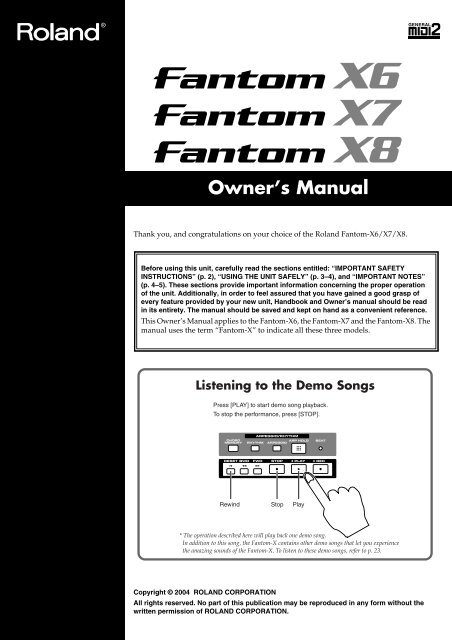
Owner’s <strong>Manual</strong>Thank you, and congratulations on your choice of the <strong>Roland</strong> Fantom-X6/X7/X8.201bBefore using this unit, carefully read the sections entitled: “IMPORTANT SAFETYINSTRUCTIONS” (p. 2), “USING THE UNIT SAFELY” (p. 3–4), and “IMPORTANT NOTES”(p. 4–5). These sections provide important information concerning the proper operationof the unit. Additionally, in order to feel assured that you have gained a good grasp ofevery feature provided by your new unit, Handbook and Owner’s manual should be readin its entirety. The manual should be saved and kept on hand as a convenient reference.This Owner’s <strong>Manual</strong> applies to the Fantom-X6, the Fantom-X7 and the Fantom-X8. Themanual uses the term “Fantom-X” to indicate all these three models.Listening to the Demo SongsPress [PLAY] to start demo song playback.To stop the performance, press [STOP].Rewind Stop Play* The operation described here will play back one demo song.In addition to this song, the Fantom-X contains other demo songs that let you experiencethe amazing sounds of the Fantom-X. To listen to these demo songs, refer to p. 23.202Copyright © 2004 ROLAND CORPORATIONAll rights reserved. No part of this publication may be reproduced in any form without thewritten permission of ROLAND CORPORATION.
WARNING: To reduce the risk of fire or electric shock, do not expose this apparatus to rain or moisture.CAUTIONRISK OF ELECTRIC SHOCKDO NOT OPENATTENTION: RISQUE DE CHOC ELECTRIQUE NE PAS OUVRIRCAUTION: TO REDUCE THE RISK OF ELECTRIC SHOCK,DO NOT REMOVE COVER (OR BACK).NO USER-SERVICEABLE PARTS INSIDE.REFER SERVICING TO QUALIFIED SERVICE PERSONNEL.The lightning flash with arrowhead symbol, within anequilateral triangle, is intended to alert the user to thepresence of uninsulated “dangerous voltage” within theproduct’s enclosure that may be of sufficient magnitude toconstitute a risk of electric shock to persons.The exclamation point within an equilateral triangle isintended to alert the user to the presence of importantoperating and maintenance (servicing) instructions in theliterature accompanying the product.INSTRUCTIONS PERTAINING TO A RISK OF FIRE, ELECTRIC SHOCK, OR INJURY TO PERSONS.IMPORTANT SAFETY INSTRUCTIONSSAVE THESE INSTRUCTIONSWARNING - When using electric products, basic precautions should always be followed, including the following:1. Read these instructions.2. Keep these instructions.3. Heed all warnings.4. Follow all instructions.5. Do not use this apparatus near water.6. Clean only with a dry cloth.7. Do not block any of the ventilation openings. Install inaccordance with the manufacturers instructions.8. Do not install near any heat sources such as radiators,heat registers, stoves, or other apparatus (includingamplifiers) that produce heat.9. Do not defeat the safety purpose of the polarized orgrounding-type plug. A polarized plug has two blades withone wider than the other. A grounding type plug has twoblades and a third grounding prong. The wide blade or thethird prong are provided for your safety. If the provided plugdoes not fit into your outlet, consult an electrician forreplacement of the obsolete outlet.10. Protect the power cord from being walked on or pinchedparticularly at plugs, convenience receptacles, and thepoint where they exit from the apparatus.11. Only use attachments/accessories specified by themanufacturer.12. Use only with the cart, stand, tripod, bracket,or table specified by the manufacturer, orsold with the apparatus. When a cart is used,use caution when moving the cart/apparatuscombination to avoid injury from tip-over.13. Unplug this apparatus during lightning storms or whenunused for long periods of time.14. Refer all servicing to qualified service personnel. Servicingis required when the apparatus has been damaged in anyway, such as power-supply cord or plug is damaged, liquidhas been spilled or objects have fallen into the apparatus,the apparatus has been exposed to rain or moisture, doesnot operate normally, or has been dropped.WARNING:IMPORTANT:For the U.K.THIS APPARATUS MUST BE EARTHEDTHE WIRES IN THIS MAINS LEAD ARE COLOURED IN ACCORDANCE WITH THE FOLLOWING CODE.GREEN-AND-YELLOW: EARTH, BLUE: NEUTRAL, BROWN: LIVEAs the colours of the wires in the mains lead of this apparatus may not correspond with the coloured markings identifyingthe terminals in your plug, proceed as follows:The wire which is coloured GREEN-AND-YELLOW must be connected to the terminal in the plug which is marked by theletter E or by the safety earth symbol or coloured GREEN or GREEN-AND-YELLOW.The wire which is coloured BLUE must be connected to the terminal which is marked with the letter N or coloured BLACK.The wire which is coloured BROWN must be connected to the terminal which is marked with the letter L or coloured RED.2
USING THE UNIT SAFELYUsed for instructions intended to alertthe user to the risk of death or severeinjury should the unit be usedimproperly.Used for instructions intended to alertthe user to the risk of injury or materialdamage should the unit be usedimproperly.* Material damage refers to damage orother adverse effects caused withrespect to the home and all itsfurnishings, as well to domesticanimals or pets.The symbol alerts the user to important instructionsor warnings.The specific meaning of the symbol isdetermined by the design contained within thetriangle. In the case of the symbol at left, it is used forgeneral cautions, warnings, or alerts to danger.The symbol alerts the user to items that must neverbe carried out (are forbidden). The specific thing thatmust not be done is indicated by the design containedwithin the circle. In the case of the symbol at left, itmeans that the unit must never be disassembled.The ● symbol alerts the user to things that must becarried out. The specific thing that must be done isindicated by the design contained within the circle. Inthe case of the symbol at left, it means that the powercordplug must be unplugged from the outlet.001• Before using this unit, make sure to read the instructions below,and the Owner’s <strong>Manual</strong>...........................................................................................................002b• Connect mains plug of this model to a mains socket outlet with aprotective earthing connection...........................................................................................................• Do not open or perform any internal modifications on the unit.(The only exception would be where this manual providesspecific instructions which should be followed in order to put inplace user-installable options; see p. 240, p. 242, p. 244, p. 246.)..........................................................................................................003• Do not attempt to repair the unit, or replace parts within it (exceptwhen this manual provides specific instructions directing you todo so). Refer all servicing to your retailer, the nearest <strong>Roland</strong>Service Center, or an authorized <strong>Roland</strong> distributor, as listed onthe “Information” page...........................................................................................................004• Never use or store the unit in places that are:• Subject to temperature extremes (e.g., direct sunlight in anenclosed vehicle, near a heating duct, on top of heat-generatingequipment); or are• Damp (e.g., baths, washrooms, on wet floors); or are• Humid; or are• Exposed to rain; or are• Dusty; or are• Subject to high levels of vibration...........................................................................................................005• This unit should be used only with a rack or stand that is recommendedby <strong>Roland</strong>...........................................................................................................006• When using the unit with a rack or stand recommended by<strong>Roland</strong>, the rack or stand must be carefully placed so it is leveland sure to remain stable. If not using a rack or stand, you stillneed to make sure that any location you choose for placing theunit provides a level surface that will properly support the unit,and keep it from wobbling...........................................................................................................008a• The unit should be connected to a power supply only of the typedescribed in the operating instructions, or as marked on the unit...........................................................................................................008e• Use only the attached power-supply cord. Also, the suppliedpower cord must not be used with any other device...........................................................................................................009• Do not excessively twist or bend the power cord, nor place heavyobjects on it. Doing so can damage the cord, producing severedelements and short circuits. Damaged cords are fire and shockhazards!..........................................................................................................010• This unit, either alone or in combination with an amplifier andheadphones or speakers, may be capable of producing soundlevels that could cause permanent hearing loss. Do not operate fora long period of time at a high volume level, or at a level that isuncomfortable. If you experience any hearing loss or ringing inthe ears, you should immediately stop using the unit, and consultan audiologist...........................................................................................................011• Do not allow any objects (e.g., flammable material, coins, pins); orliquids of any kind (water, soft drinks, etc.) to penetrate the unit...........................................................................................................012a:• Immediately turn the power off, remove the power cord from theoutlet, and request servicing by your retailer, the nearest <strong>Roland</strong>Service Center, or an authorized <strong>Roland</strong> distributor, as listed onthe “Information” page when:• The power-supply cord, or the plug has been damaged; or• If smoke or unusual odor occurs• Objects have fallen into, or liquid has been spilled onto theunit; or• The unit has been exposed to rain (or otherwise has becomewet); or• The unit does not appear to operate normally or exhibits amarked change in performance...........................................................................................................013• In households with small children, an adult should providesupervision until the child is capable of following all the rulesessential for the safe operation of the unit...........................................................................................................014• Protect the unit from strong impact.(Do not drop it!)..........................................................................................................015• Do not force the unit’s power-supply cord to share an outlet withan unreasonable number of other devices. Be especially carefulwhen using extension cords—the total power used by all devicesyou have connected to the extension cord’s outlet must neverexceed the power rating (watts/amperes) for the extension cord.Excessive loads can cause the insulation on the cord to heat upand eventually melt through...........................................................................................................016• Before using the unit in a foreign country, consult with yourretailer, the nearest <strong>Roland</strong> Service Center, or an authorized<strong>Roland</strong> distributor, as listed on the “Information” page...........................................................................................................3
022a• Always turn the unit off and unplug the power cord beforeattempting installation of the circuit board (SRX series; p. 240, p.242, DIMM; p. 244, p. 246)...........................................................................................................023• DO NOT play a CD-ROM disc on a conventional audio CDplayer. The resulting sound may be of a level that could causepermanent hearing loss. Damage to speakers or other systemcomponents may result...........................................................................................................026• Do not put anything that contains water (e.g., flower vases) on thisunit. Also, avoid the use of insecticides, perfumes, alcohol, nail polish,spray cans, etc., near the unit. Swiftly wipe away any liquid that spillson the unit using a dry, soft cloth...........................................................................................................101a• The unit should be located so that its location or position does notinterfere with its proper ventilation...........................................................................................................101c• This unit for use only with <strong>Roland</strong> stand KS-12 (Fantom-X6/Fantom-X7) / KS-17 (Fantom-X8). Use with other stands (or carts)is capable of resulting in instability causing possible injury...........................................................................................................102b• Always grasp only the plug on the power-supply cord whenplugging into, or unplugging from, an outlet or this unit...........................................................................................................103a:• At regular intervals, you should unplug the power plug and cleanit by using a dry cloth to wipe all dust and other accumulationsaway from its prongs. Also, disconnect the power plug from thepower outlet whenever the unit is to remain unused for anextended period of time. Any accumulation of dust between thepower plug and the power outlet can result in poor insulation andlead to fire.104• Try to prevent cords and cables from becoming entangled. Also,all cords and cables should be placed so they are out of the reachof children...........................................................................................................106• Never climb on top of, nor place heavy objects on the unit...........................................................................................................107b• Never handle the power cord or its plugs with wet hands whenplugging into, or unplugging from, an outlet or this unit...........................................................................................................108a• Before moving the unit, disconnect the power plug from theoutlet, and pull out all cords from external devices...........................................................................................................109a• Before cleaning the unit, turn off the power and unplug the powercord from the outlet (p. 22)...........................................................................................................110a• Whenever you suspect the possibility of lightning in your area,pull the plug on the power cord out of the outlet...........................................................................................................115a• Install only the specified circuit board(s) (SRX Series, DIMM).Remove only the specified screws (p. 240, p. 242, p. 244, p. 246, p.248)...........................................................................................................118• Should you remove the screws that fasten the bottom panel (thefront panel of the Fantom-X8) or the PC card protector, be sure toplace them out of children’s reach, so there is no chance of thembeing swallowed accidentally...........................................................................................................IMPORTANT NOTES291bIn addition to the items listed under “IMPORTANT SAFETY INSTRUCTIONS” and “USING THE UNIT SAFELY” on pages 2–4, please readand observe the following:Power Supply301• Do not connect this unit to same electrical outlet that is being used by anelectrical appliance that is controlled by an inverter (such as a refrigerator,washing machine, microwave oven, or air conditioner), or that contains amotor. Depending on the way in which the electrical appliance is used,power supply noise may cause this unit to malfunction or may produceaudible noise. If it is not practical to use a separate electrical outlet, connecta power supply noise filter between this unit and the electrical outlet.307• Before connecting this unit to other devices, turn off the power to all units.This will help prevent malfunctions and/or damage to speakers or otherdevices.308• Although the LCD and LEDs are switched off when the POWER switch isswitched off, this does not mean that the unit has been completely disconnectedfrom the source of power. If you need to turn off the powercompletely, first turn off the POWER switch, then unplug the power cordfrom the power outlet. For this reason, the outlet into which you choose toconnect the power cord's plug should be one that is within easy reach andreadily accessible.Placement351• Using the unit near power amplifiers (or other equipment containing largepower transformers) may induce hum. To alleviate the problem, changethe orientation of this unit; or move it farther away from the source ofinterference.352a• This device may interfere with radio and television reception. Do not usethis device in the vicinity of such receivers.352b• Noise may be produced if wireless communications devices, such as cellphones, are operated in the vicinity of this unit. Such noise could occurwhen receiving or initiating a call, or while conversing. Should youexperience such problems, you should relocate such wireless devices sothey are at a greater distance from this unit, or switch them off.354a• Do not expose the unit to direct sunlight, place it near devices that radiateheat, leave it inside an enclosed vehicle, or otherwise subject it to temperatureextremes. Excessive heat can deform or discolor the unit.355b• When moved from one location to another where the temperature and/orhumidity is very different, water droplets (condensation) may form insidethe unit. Damage or malfunction may result if you attempt to use the unitin this condition. Therefore, before using the unit, you must allow it tostand for several hours, until the condensation has completely evaporated.358• Do not allow objects to remain on top of the keyboard. This can be thecause of malfunction, such as keys ceasing to produce sound.4
IMPORTANT NOTESMaintenance401a• For everyday cleaning wipe the unit with a soft, dry cloth or one that hasbeen slightly dampened with water. To remove stubborn dirt, use a clothimpregnated with a mild, non-abrasive detergent. Afterwards, be sure towipe the unit thoroughly with a soft, dry cloth.402• Never use benzine, thinners, alcohol or solvents of any kind, to avoid thepossibility of discoloration and/or deformation.Repairs and Data452• Please be aware that all data contained in the unit’s memory may be lostwhen the unit is sent for repairs. Important data should always be backedup on a memory card, or written down on paper (when possible). Duringrepairs, due care is taken to avoid the loss of data. However, in certaincases (such as when circuitry related to memory itself is out of order), weregret that it may not be possible to restore the data, and <strong>Roland</strong> assumesno liability concerning such loss of data.Additional Precautions551• Please be aware that the contents of memory can be irretrievably lost as aresult of a malfunction, or the improper operation of the unit. To protectyourself against the risk of loosing important data, we recommend thatyou periodically save a backup copy of important data you have stored inthe unit’s memory on a memory card, or other device.552• Unfortunately, it may be impossible to restore the contents of data that wasstored on a memory card, unit’s memory, or other device once it has beenlost. <strong>Roland</strong> Corporation assumes no liability concerning such loss of data.553• Use a reasonable amount of care when using the unit’s buttons, sliders, orother controls; and when using its jacks and connectors. Rough handlingcan lead to malfunctions.554• Never strike or apply strong pressure to the display.555• A small amount of noise may be heard from the display during normaloperation.556• When connecting / disconnecting all cables, grasp the connector itself—never pull on the cable. This way you will avoid causing shorts, or damageto the cable’s internal elements.557• A small amount of heat will radiate from the unit during normal operation.558a• To avoid disturbing your neighbors, try to keep the unit’s volume atreasonable levels. You may prefer to use headphones, so you do not needto be concerned about those around you (especially when it is late atnight).559a• When you need to transport the unit, package it in the box (includingpadding) that it came in, if possible. Otherwise, you will need to use equivalentpackaging materials.561• Use only the specified expression pedal (EV-5; sold separately). Byconnecting any other expression pedals, you risk causing malfunctionand/or damage to the unit.562• Use a cable from <strong>Roland</strong> to make the connection. If using some other makeof connection cable, please note the following precautions.• Some connection cables contain resistors. Do not use cables that incorporateresistors for connecting to this unit. The use of such cables cancause the sound level to be extremely low, or impossible to hear. Forinformation on cable specifications, contact the manufacturer of thecable.566b• The sensitivity of the D Beam controller will change depending on theamount of light in the vicinity of the unit. If it does not function as youexpect, adjust the sensitivity as appropriate for the brightness of yourlocation. Increase this value will raise the sensitivity (p. 226).Before Using CardsUsing Memory Cards704• Carefully insert the memory Card all the way in—until it is firmly in place.705• Never touch the terminals of the memory card. Also, avoid getting theterminals dirty.707• This unit’s memory card slot accepts CompactFlash, Smartmedia (3.3V).708• CompactFlash, Smartmedia (3.3V) are constructed using precision components;handle the cards carefully, paying particular note to the following.• To prevent damage to the cards from static electricity, be sure todischarge any static electricity from your own body before handling thecards.• Do not touch or allow metal to come into contact with the contactportion of the cards.• Do not bend, drop, or subject cards to strong shock or vibration.• Do not keep cards in direct sunlight, in closed vehicles, or other suchlocations (storage temperature: -25 to 85° C).• Do not allow cards to become wet.• Do not disassemble or modify the cards.Handling CD-ROMs801• Avoid touching or scratching the shiny underside (encoded surface) of thedisc. Damaged or dirty CD-ROM discs may not be read properly. Keepyour discs clean using a commercially available CD cleaner.Copyright851• Unauthorized recording, distribution, sale, lending, public performance,broadcasting, or the like, in whole or in part, of a work (musical composition,video, broadcast, public performance, or the like) whose copyright isheld by a third party is prohibited by law.852a• When exchanging audio signals through a digital connection with anexternal instrument, this unit can perform recording without being subjectto the restrictions of the Serial Copy Management System (SCMS). This isbecause the unit is intended solely for musical production, and is designednot to be subject to restrictions as long as it is used to record works (such asyour own compositions) that do not infringe on the copyrights of others.(SCMS is a feature that prohibits second-generation and later copyingthrough a digital connection. It is built into MD recorders and otherconsumer digital-audio equipment as a copyright-protection feature.)853• Do not use this unit for purposes that could infringe on a copyright held bya third party. We assume no responsibility whatsoever with regard to anyinfringements of third-party copyrights arising through your use of thisunit.237204* Microsoft and Windows are registered trademarks of Microsoft Corporation.206j* Windows® is known officially as: “Microsoft® Windows® operatingsystem.”207* Apple and Macintosh are registered trademark of Apple Computer, Inc.209* MacOS is a trademark of Apple Computer, Inc.213* Pentium is a registered trademark of Intel Corporation.220* All product names mentioned in this document are trademarks or registeredtrademarks of their respective owners.230* SmartMedia is a trademark of Toshiba Corp.231* OMS is a registered trademark of Opcode Systems, Inc.234* CompactFlash and are trademarks of SanDisk Corporation andlicensed by CompactFlash association.235* <strong>Roland</strong> Corporation is an authorized licensee of the CompactFlash andCF logo () trademarks.5
ContentsUSING THE UNIT SAFELY ..............................................................................3IMPORTANT NOTES........................................................................................4Main Features ................................................................................................15Panel Descriptions ........................................................................................16Front Panel................................................................................................................................................. 16Rear Panel.................................................................................................................................................. 18Getting Ready ................................................................................................19Connecting an Amp and Speaker System............................................................................................. 19Placing the Fantom-X8 on a Stand (For Fantom-X8 user) ................................................................. 20Turning On the Power ............................................................................................................................. 21Adjusting the Display Contrast (LCD Contrast).................................................................................. 22Turning Off the Power............................................................................................................................. 22Listening to the Demo Songs.......................................................................23Listening to the demo song loaded when you start up the Fantom-X ............................................. 23Listening to the other demo songs......................................................................................................... 23Various Performance Features ....................................................................24Velocity/Aftertouch ..................................................................................................................... 24Pitch Bend/Modulation Lever.................................................................................................... 24Octave Shift (Oct) .......................................................................................................................... 24Hold Pedal...................................................................................................................................... 24Control Pedal ................................................................................................................................. 25Transpose (Trans).......................................................................................................................... 25Overview of the Fantom-X ............................................................................26How the Fantom-X Is Organized ........................................................................................................... 26Basic Structure ............................................................................................................................... 26Classification of Fantom-X Sound Types................................................................................... 26About Simultaneous Polyphony................................................................................................. 28About Memory.......................................................................................................................................... 28Temporary Memory...................................................................................................................... 29Rewritable Memory ...................................................................................................................... 29Non-Rewritable Memory............................................................................................................. 29About the Onboard Effects ..................................................................................................................... 29Effect Types.................................................................................................................................... 29How Effects Units Work in Different Modes............................................................................ 30About the Sequencer ................................................................................................................................ 30What Is a Song? ............................................................................................................................. 30What Is a Track? ............................................................................................................................ 30Songs and the Sound Generator Mode ...................................................................................... 31Positions for Storing a Song......................................................................................................... 31About the Sampling Section.................................................................................................................... 32Where Samples are Stored ........................................................................................................... 32Basic Operation of the Fantom-X ........................................................................................................... 33Switching the Sound Generator Mode....................................................................................... 33About the Function Buttons ........................................................................................................ 34Moving the Cursor........................................................................................................................ 34Modifying a Value ........................................................................................................................ 35Assigning a Name......................................................................................................................... 36Registering and recalling frequently used screen pages (Bookmark) .............................................. 37Registering a page......................................................................................................................... 37Recalling a page............................................................................................................................. 37Viewing an explanation of each button (Help) ....................................................................................37Viewing the number of voices used by the sound generator (Voice Monitor) ............................... 376
ContentsPlaying in Patch Mode ..................................................................................38About the Patch Play Screen................................................................................................................... 38Displaying Patch Play Screen...................................................................................................... 38Selecting a Patch ....................................................................................................................................... 39Selecting Patches by Category (Patch Finder) .......................................................................... 40Selecting Patches from the List.................................................................................................... 41Auditioning Patches (Phrase Preview) ...................................................................................... 42Creating a list of frequently used Patches and Performances (Live Setting).................................. 42Recalling sounds ........................................................................................................................... 42Registering a sound ...................................................................................................................... 43Removing a registration............................................................................................................... 43Removing all sound registrations from a bank ........................................................................ 43Changing the step at which a sound is registered ................................................................... 43Selecting Favorite Patches (Favorite Patch).......................................................................................... 44Registering a Favorite Patch........................................................................................................ 44Registering Favorite Rhythm Sets .............................................................................................. 45Transposing the Keyboard in Octave Units (Octave Shift) ................................................................ 45Transposing the Keyboard in Semitone Steps (Transpose)................................................................ 46Selecting the Tones That Will Sound (Tone On/Off).......................................................................... 46Playing Single Notes (Monophonic)...................................................................................................... 46Creating Smooth Pitch Changes (Portamento) .................................................................................... 47Selecting the Parameter Controlled by the Realtime Controllers or D Beam Controller(Control Setting) ....................................................................................................................................... 47Specifying the Part that Will be Affected by the Controller ................................................... 47Assigning a Parameter to a Controller....................................................................................... 48Playing Percussion Instruments............................................................................................................. 52Selecting a Rhythm Set ................................................................................................................. 52Playing a Rhythm Set ................................................................................................................... 53Playing in Piano Mode ..................................................................................54Selecting Piano Mode............................................................................................................................... 54Selecting a Patch ....................................................................................................................................... 54Selecting Patches by Category..................................................................................................... 54Selecting from the Patch List Screen........................................................................................... 54Playing acoustic piano sounds ............................................................................................................... 54Adjusting the Keyboard Touch (Key Touch)............................................................................ 54Changing the Piano Sound (Open/Close) ................................................................................ 55Adjusting the Depth of Resonance (Resonance)....................................................................... 55Playing electric piano sounds ................................................................................................................. 55Selecting electric piano effects..................................................................................................... 55Saving a Sound (Patch)............................................................................................................................ 55Creating a Patch ............................................................................................56How to Make Patch Settings................................................................................................................... 56Editing in a Graphic Display (Zoom Edit) ................................................................................ 57Initializing Patch Settings (Init)................................................................................................... 57Copying Patch (Tone) Settings (Copy)....................................................................................... 58Cautions When Selecting a Waveform ...................................................................................... 58Saving Patches You’ve Created (Write) ................................................................................................ 59Auditioning the Save-Destination Patch (Compare) ............................................................... 60Functions of Patch Parameters ............................................................................................................... 60Settings Common to the Entire Patch (General)....................................................................... 60Modifying Waveforms (Wave) ................................................................................................... 62Changing How a Tone Is Sounded (TMT) ................................................................................ 63Modifying Pitch (Pitch/Pitch Env)............................................................................................. 67Modifying the Brightness of a Sound with a Filter (TVF/TVF Env)..................................... 69Adjusting the Volume (TVA/TVA Env) ................................................................................... 717
ContentsOutput............................................................................................................................................. 73Modulating Sounds (LFO)........................................................................................................... 74Apply Portamento or Legato to the Sound (Solo/Porta) ........................................................ 77Miscellaneous Settings (Misc) ..................................................................................................... 78Matrix Control Settings (Ctrl1–4)................................................................................................ 80Setting Effects for a Patch (Effects/MFX/MFX Control/Chorus/Reverb).......................... 82Creating a Rhythm Set ..................................................................................83How to make Rhythm Set settings......................................................................................................... 83Editing in a Graphic Display (Zoom Edit) ................................................................................ 84Initializing Rhythm Set Settings (Init)........................................................................................ 84Copying Rhythm Tone Settings (Copy)..................................................................................... 84Cautions When Selecting a Waveform ...................................................................................... 85Saving Rhythm Sets You’ve Created (Write) .......................................................................................86Auditioning the Save-Destination Rhythm Set (Compare) .................................................... 86Functions of Rhythm Set Parameters .................................................................................................... 87Making Settings Common to the Entire Rhythm Set (General) ............................................. 87Modifying Waveforms (Wave) ................................................................................................... 88Changing How a Rhythm Tone Is Sounded (WMT) ............................................................... 89Modifying Pitch (Pitch/Pitch Env)............................................................................................. 90Modifying the Brightness of a Sound with a Filter (TVF/TVF Env)..................................... 92Adjusting the Volume (TVA/TVA Env) ................................................................................... 94Output Settings (Output)............................................................................................................. 95Setting Effects for a Rhythm Set (Effects/MFX/MFX Control/Chorus/Reverb) ............... 96Playing in Performance Mode ......................................................................97Displaying Performance Layer Screen .................................................................................................. 97Displaying Performance Mixer Screen.................................................................................................. 97Functions in the PERFORMANCE Layer/Mixer Screen.................................................................... 98Selecting a Performance........................................................................................................................... 99Selecting Performances from the List......................................................................................... 99Creating a list of frequently used Patches and Performances (the Live Setting function) ............ 99Selecting Favorite Performances .......................................................................................................... 100Registering a Favorite Performance ......................................................................................... 100Using the Layer Screen .......................................................................................................................... 100Selecting a Part ............................................................................................................................ 100Selecting the Part that You want to Sound (Keyboard Switch)............................................ 101Selecting the Sound for a Part ................................................................................................... 101Combining and Playing Sounds Together (Layer) ................................................................ 102Playing Different Sounds in Different Areas of the Keyboard (Split)................................. 102Using the Mixer Screen.......................................................................................................................... 103Selecting Parts for a Layer or Split............................................................................................ 103Selecting the Sound for a Part ................................................................................................... 103Editing the Part Settings............................................................................................................. 104Selecting a Part to Play Individually (Solo)............................................................................. 105Silencing the Playback of a Specific Part (Mute) .................................................................... 105Using pads to mute Parts........................................................................................................... 105Viewing the Part Settings as a List (Performance Part View).......................................................... 106Performing with the Arpeggio/Rhythm function............................................................................. 106Performing with the Realtime Controllers and D Beam Controller ............................................... 106Viewing MIDI messages for each Part (Part Information) ............................................................... 106Viewing the number of voices used by the sound generator (Voice Monitor) ............................. 106Adjusting the Master Level................................................................................................................... 1068
ContentsCreating a Performance ..............................................................................107Viewing the Part Settings as a List (Performance Part View).......................................................... 107Adjusting the Parameters of Each Part .................................................................................... 107Selecting the Parameter Controlled by the Realtime Controllers or D Beam Controller(Control Setting) ..................................................................................................................................... 114Make Settings for the Realtime Controllers and D Beam Controller (Ctrl)........................ 114Control Switch Settings (Ctrl Switch) ...................................................................................... 118Changing the Settings of the Patch Assigned to a Part..................................................................... 119Initializing Performance Settings (Init) ............................................................................................... 119Saving a Performance You’ve Created (Write) .................................................................................. 120Modifying the Sound in Real Time.............................................................121Waving Your Hand Over the D Beam to Modify the Sound (D Beam Controller) ...................... 121Making Settings for the D Beam Controller............................................................................ 122Using Knobs or Buttons to Modify the Sound (Realtime Controller) ............................................ 124Changing Realtime Controller Settings ................................................................................... 125Using a Pedal to Modify the Sound (Control Pedal)......................................................................... 126Making Control Pedal Settings ................................................................................................. 126Playing Arpeggios .......................................................................................128About Arpeggio...................................................................................................................................... 128Playing Arpeggios.................................................................................................................................. 128Turning Arpeggio On and Off .................................................................................................. 128Determining the Tempo for Arpeggio Performances............................................................ 128Holding an Arpeggio.................................................................................................................. 128Playing Arpeggios Along with the Sequencer ................................................................................... 129Arpeggio Settings ................................................................................................................................... 129Selecting Styles for Arpeggio Performances (Arpeggio Style) ............................................. 129Changing the Beat and Shuffle (Arp/Rhythm Grid)............................................................. 129Applying Staccato and Tenuto (Arp/Rhythm Duration) ..................................................... 130Selecting Ascending/Descending Variations (Different Ways of Playing the Sounds)(Arp Motif) ................................................................................................................................... 130Adjusting the Velocity of the Arpeggio (Arp Velocity)......................................................... 130Selecting the Part that Will Play Arpeggios in Performance Mode (Arp Part).................. 130Changing the Accent Strength (Arp Accent) .......................................................................... 130Hanging the Range of the Arpeggio (Oct Range) .................................................................. 131Using the Realtime Control Knobs to Edit the Arpeggio Settings....................................... 131Creating an Arpeggio Style (Arpeggio Style Edit) ............................................................................ 131Step-recording ............................................................................................................................. 131Using the Dial or [INC][DEC] to Input Values....................................................................... 132Saving the Styles You Have Created (Write)...................................................................................... 132Using the Chord Memory Function (Chord Memory)...............................133About the Chord Memory Function.................................................................................................... 133Performing with the Chord Memory Function.................................................................................. 133Turning Chord Memory Function On and Off....................................................................... 133Selecting Chord Forms ............................................................................................................... 133Sounding a chord in the order of its notes (Rolled Chord)................................................... 134Creating Your Own Chord Forms ....................................................................................................... 134Saving the Chord Forms You Have Created...................................................................................... 1349
Contents10Playing Rhythms .........................................................................................135About Rhythm Patterns......................................................................................................................... 135Using Rhythm Groups........................................................................................................................... 135Playing Rhythm ...................................................................................................................................... 135Turning Rhythm On and Off..................................................................................................... 135Determining the Tempo for Rhythm Pattern Performances ................................................ 135Select the Rhythm Group........................................................................................................... 136Rhythm Pattern Settings........................................................................................................................ 136Selecting Rhythm Patterns......................................................................................................... 136Changing the Beat and Shuffle (Grid)...................................................................................... 137Applying Staccato and Tenuity (Duration)............................................................................. 137Changing the velocity of Rhythm Pattern (Rhythm Pattern Velocity) ............................... 137Changing the Accent Strength (Rhythm Accent) ................................................................... 137Using the Realtime Control Knobs to Control the Rhythm.................................................. 137Creating an Rhythm Pattern (Rhythm Pattern Edit)......................................................................... 138Step-recording ............................................................................................................................. 138Using the Dial or [INC][DEC] to Input Values....................................................................... 138Saving the Patterns You Have Created (Write) ................................................................................. 139Creating Your Own Styles (Rhythm Group Edit).............................................................................. 139Saving the Rhythm Group You Have Created (Write)..................................................................... 140Sampling ......................................................................................................141Switching external input on/off........................................................................................................... 141Making Input Source Settings (Input Setting).................................................................................... 141Input Effect Setup Settings.................................................................................................................... 142Sampling Procedure............................................................................................................................... 142Dividing a Sample During Sampling....................................................................................... 144Sampling Earlier in Time (Skip Back Sampling)................................................................................ 145Editing a Sample..........................................................................................146Selecting a Sample (Sample List).......................................................................................................... 146Selecting a Sample....................................................................................................................... 146Loading a Sample........................................................................................................................ 147Loading all Samples.................................................................................................................... 147Unloading a Sample.................................................................................................................... 147Deleting a Sample ....................................................................................................................... 147Importing an Audio File ............................................................................................................ 148Displaying Sample Edit Screen ............................................................................................................ 148Magnifying/Shrinking the Waveform Display (Zoom In/Out).......................................... 148Setting the Start/End Points of the Sample........................................................................................ 149Using the knobs to edit the points............................................................................................ 149Making Settings for Sample (Sample Parameters) ............................................................................ 150Assigning Samples to a Pad (Assign To Pad) .................................................................................... 151From Patch Mode........................................................................................................................ 151From Performance Mode ........................................................................................................... 151Assigning a Sample as a Patch to a Part (Assign to Keyboard)....................................................... 152From Patch Mode........................................................................................................................ 152From Performance Mode ........................................................................................................... 152Create a Rhythm Set (Create Rhythm) ................................................................................................ 152Creating a Multisample (Create Multisample) .................................................................................. 153Unloading a Sample (Unload) .............................................................................................................. 155Removing Unwanted Portions of a Sample (Truncate) .................................................................... 155Boosting or Limiting the High-frequency Range of the Sample (Emphasis) ................................ 155Maximizing the Volume of a Sample (Normalize)............................................................................ 156Amp.......................................................................................................................................................... 156Stretching or Shrinking a Sample (Time Stretch)............................................................................... 156Dividing a Sample into Notes (Chop) ................................................................................................. 157Joining Two or More Samples (Combine) .......................................................................................... 158Saving a Sample...................................................................................................................................... 159
ContentsUsing the Pads.............................................................................................160Using the Hold Function to Sustain a Sound ..................................................................................... 160Using the Roll Function to Play Sounds.............................................................................................. 160Making Settings for the Pads (Pad Setting) ........................................................................................ 161Specify the Currently Used Sound Generator ........................................................................ 161Settings You Can Make for Each Pad....................................................................................... 161Settings that Apply to All Pads................................................................................................. 161Writing the Pad Settings ............................................................................................................ 162Exchanging the Sound of Two Pads (Pad Exchange) ............................................................ 162Assigning a Pattern to a Pad (RPS Function) ..................................................................................... 163Using the Pads to Play Rhythms.......................................................................................................... 163Playing Back a Song ...................................................................................164Playing a Song Immediately (Quick Play).......................................................................................... 164Playing Back Songs Consecutively (Chain Play) ............................................................................... 164Various Playback Methods ................................................................................................................... 165Fast-Forward and Rewind During Playback .......................................................................... 165Playing Back Correctly from the Middle of the Song (MIDI Update)................................. 165Muting the Playback of a Specific Instrument........................................................................ 165Changing the Playback Tempo of a Song................................................................................ 166Playing a Song Back at a Fixed Tempo (Muting the Tempo Track) .................................... 166Playing Back a S-MRC Format Song ........................................................................................ 166Playing Back a Song Repeatedly (Loop Play) ......................................................................... 166Using the D Beam Controller to Start/Stop Song Playback ................................................. 167Recording Songs.........................................................................................168Two Recording Methods............................................................................................................ 168Before You Record a New Song ........................................................................................................... 168Select the Sound to be Used for Recording ............................................................................. 168Erasing the Song/Pattern from Temporary Song (Song Clear) ........................................... 168Specify the Time Signature ........................................................................................................ 169Setting the tempo ........................................................................................................................ 169Recording Your Performance as You Play It (Realtime Recording) ............................................... 170Basic Operation for Realtime Recording ................................................................................. 170Recording Tempo Changes in a Song (Tempo Recording)................................................... 171Loop Recording and Punch-In Recording............................................................................... 171Correct the Timing of Your Playing as You Record (Recording Quantize) ....................... 172Selecting the Sequencer Data that will Be Recorded (Recording Select) ............................ 172Erasing Unwanted Data While You Record (Realtime Erase).............................................. 173Recording Arpeggios Aligned to the Measures of the Sequencer ....................................... 173Auditioning Sounds or Phrases While Recording (Rehearsal Function)............................ 173Inputting Data One Step at a Time (Step Recording)........................................................................ 174Inputting Notes and Rests ......................................................................................................... 174Assigning a Pattern to a Phrase Track ..................................................................................... 176Editing Songs ..............................................................................................177Loading the Song You Want to Edit .................................................................................................... 177Viewing the data within a track................................................................................................ 178Using Different Sound Generators for Each Track ................................................................ 178Loading Individual Tracks/Patterns of Song Data................................................................ 178Silencing the Playback of a Track (Mute) ................................................................................ 178Assigning Markers (Locate Positions) to a Song .................................................................... 179Specifying the Area of a Song that will Repeat (Loop Points).............................................. 179Editing Sequencer Data Over the Specified Range (Track Edit) ..................................................... 180Basic Operation for Track Editing ............................................................................................ 180Aligning a Song’s Timing (Quantize) ...................................................................................... 181Erasing Unwanted Performance Data (Erase) ........................................................................ 183Deleting Unwanted Measures (Delete).................................................................................... 184Copying Phrases (Copy) ............................................................................................................ 18411
ContentsInserting a Blank Measure (Insert) ........................................................................................... 185Transpose the Key (Transpose)................................................................................................. 185Changing the Velocity (Volume) (Change Velocity) ............................................................. 186Changing the MIDI Channel (Change Channel).................................................................... 186Modifying the Length of Notes (Change Duration) .............................................................. 187Combining Two Phrase Tracks or Patterns into One (Merge) ............................................. 188Extracting and Moving a Part of Sequencer Data (Extract) .................................................. 188Shifting Performance Data Forward and Back (Shift Clock) ................................................ 189Thinning Out the Sequencer Data (Data Thin)....................................................................... 190Swapping Two Phrase Tracks or Patterns (Exchange).......................................................... 191Adjusting the Song’s Playback Time (Time Fit) ..................................................................... 191Deleting Blank Measures (Truncate)........................................................................................ 191Editing Individual Items of Sequencer Data (Micro Edit)................................................................ 192Editing Sequencer Data (Basic Procedure in the Microscope).............................................. 192Sequencer Data Handled by a Phrase Track/Pattern............................................................ 193Viewing Sequencer Data (View) ............................................................................................... 194Inserting Sequencer Data (Create)............................................................................................ 194Erasing Sequencer Data (Erase) ................................................................................................ 195Moving Sequencer Data (Move) ............................................................................................... 195Copying Sequencer Data (Copy) .............................................................................................. 195Changing the Tempo Midway Through the Song ................................................................. 196Changing the Time Signature Midway Through the Song................................................... 196Assigning a Name to a Song (Song Name)......................................................................................... 197Saving/Loading a song (Save/Load)..........................................................198Saving a Song (Save) .............................................................................................................................. 198Basic Procedure ........................................................................................................................... 198Data saved together with a song............................................................................................... 198Saving a Song with Samples (Save Song+Samples)............................................................... 199Saving a Song (Save Song)......................................................................................................... 199Saving Samples (Save All Samples).......................................................................................... 200Saving a Song as an SMF File (Save as SMF)...................................................................................... 200Loading a Song (Load)........................................................................................................................... 201Basic Procedure ........................................................................................................................... 201Loading a Song with Samples (Load Song+Samples) ........................................................... 201Loading a song (Load Song)...................................................................................................... 202Loading Samples (Load All Samples) ...................................................................................... 202Importing a WAV/AIFF File (Import Audio).................................................................................... 202Playing a Phrase at the Touch of a Finger (RPS Function) .....................203Before You Use the RPS Function ........................................................................................................ 203Record a Pattern .......................................................................................................................... 203Settings for the RPS Function .................................................................................................... 203Using the RPS Function While You Perform...................................................................................... 204Recording a Performance Using the RPS Function................................................................ 205Adding Effects .............................................................................................206Turning Effects On and Off................................................................................................................... 206Making Effect Settings ........................................................................................................................... 206Applying Effects in Patch Mode .......................................................................................................... 207Specifying How the Sound Will Be Output (Routing) .......................................................... 207Signal Flow Diagram and Parameters ..................................................................................... 207Applying Effects in Performance Mode.............................................................................................. 210Specifying How the Sound Will Be Output (Routing) .......................................................... 210Signal Flow Diagram and Parameters ..................................................................................... 210Making Multi-Effects Settings (MFX1–3)............................................................................................ 213Making Multi-Effects Settings (MFX Control) ................................................................................... 213Specifying the multi-effect structure (MFX Structure)...................................................................... 215Making Chorus Settings (Chorus) ....................................................................................................... 21512
ContentsMaking Reverb Settings (Reverb) ........................................................................................................ 216Mastering Effect...................................................................................................................................... 217Connecting to Your Computer via USB (USB Mode) ...............................218About USB Functions............................................................................................................................. 218Switching the Storage Mode and the MIDI Mode............................................................................. 218Transferring Files to or from Your Computer (Storage Mode) ....................................................... 219Exchanging MIDI Messages with Your Computer (MIDI Mode)................................................... 222File-Related Functions (File Utility)............................................................223Basic Procedure....................................................................................................................................... 223Copying a File (Copy)............................................................................................................................ 224Deleting a File (Delete) .......................................................................................................................... 224Moving a File (Move)............................................................................................................................. 224Initializing a Memory Card (Card Format) ........................................................................................ 224Settings Common to All Modes (System Function) .................................225How to Make System Function Settings ............................................................................................. 225Saving the System Settings (System Write) ........................................................................................ 225Functions of System Parameters .......................................................................................................... 226Pedal/D Beam ............................................................................................................................. 226Keyboard ...................................................................................................................................... 226Sync/Temp .................................................................................................................................. 227Metronome................................................................................................................................... 228Sound ............................................................................................................................................ 229MIDI .............................................................................................................................................. 230USB................................................................................................................................................ 231Scale Tune..................................................................................................................................... 232Preview ......................................................................................................................................... 232System Ctrl................................................................................................................................... 233Background.................................................................................................................................. 233Screen Saver ................................................................................................................................. 233Sampling....................................................................................................................................... 233Start up.......................................................................................................................................... 234System Information................................................................................................................................ 234Data Management FunctionsReset to Default Factory Settings (Factory Reset)...................................235Basic Procedure....................................................................................................................................... 235Backing Up User Data (User Backup) ................................................................................................. 235Restoring User Data that You Backed Up (User Restore) ................................................................ 235Factory Reset ........................................................................................................................................... 235Using Fantom-X Editor................................................................................236Installing Fantom-X Editor into Your Computer............................................................................... 236Making Connections .............................................................................................................................. 236Using Fantom-X Librarian .................................................................................................................... 236Fantom-X Editor System Requirements.............................................................................................. 237System Requirements (Windows) ............................................................................................ 237System Requirements (Mac OS)................................................................................................ 237About V-LINK ...............................................................................................238What is V-LINK? .................................................................................................................................... 238Connection Examples ............................................................................................................................ 238Turning the V-LINK ON/OFF ............................................................................................................. 238V-LINK Settings...................................................................................................................................... 238V-LINK Parameters .................................................................................................................... 239Resetting the Image..................................................................................................................... 23913
ContentsInstalling the Wave Expansion Board........................................................240Cautions When Installing an Wave Expansion Board...................................................................... 240How to Install a Wave Expansion Board ............................................................................................ 240Checking the Installed Wave Expansion Boards ............................................................................... 241Installation de la carte d’expansion Wave ................................................242Précautions à prendre lors de l’installation d’une carte d’expansion Wave ................................. 242Installation d’une carte d’expansion Wave ........................................................................................ 242Vérification des cartes d’extension audio aprés installation............................................................ 243Expanding the Memory ...............................................................................244Precautions for Expanding Memory ................................................................................................... 244How to Expand the Memory ................................................................................................................ 244Removing the Memory............................................................................................................... 245Checking that memory is installed correctly...................................................................................... 245Ajouter de la mémoire.................................................................................246Précautions à prendre lors de l’ajout de mémoire............................................................................. 246Installation du module de mémoire .................................................................................................... 246Retrait du module de mémoire................................................................................................. 247Vérifier que la mémoire est installée correctement ........................................................................... 247Using a Memory Card..................................................................................248Before Using the Memory Card ........................................................................................................... 248Writing data to the card......................................................................................................................... 248Installing the PC Card Protector .......................................................................................................... 248Troubleshooting ..........................................................................................249Problems Concerning the Entire Fantom-X ............................................................................ 249Issues Related to Sound ............................................................................................................. 249Issues Related to Effects ............................................................................................................. 251Issues Related to Saving Data ................................................................................................... 251Issues Related to Sequencer....................................................................................................... 252Issues Related to MIDI and External Devices......................................................................... 253Issues Related to Sampling ........................................................................................................ 254Issues Related to a Memory Card............................................................................................. 254Parameter List..............................................................................................255Patch Parameter...................................................................................................................................... 255Rhythm Set Parameter ........................................................................................................................... 259Performance Parameter ......................................................................................................................... 262Rhythm Group Parameter..................................................................................................................... 265Sample Parameters................................................................................................................................. 265System Parameters ................................................................................................................................. 266Effects List ...................................................................................................270Multi-Effects Parameter......................................................................................................................... 270Chorus Parameters................................................................................................................................. 293Reverb Parameters ................................................................................................................................. 294Input Effect Parameters ......................................................................................................................... 294Error Messages............................................................................................296About MIDI....................................................................................................297About MIDI Connectors............................................................................................................. 297MIDI Channels and Multi-timbral Sound Generators........................................................... 297MIDI Implementation ...................................................................................298Specifications ..............................................................................................333Index .............................................................................................................33514
Main FeaturesCutting-edge sound engine thatunifies audio and MIDIThe Fantom-X inherits the same sound engine that was acclaimed onthe Fantom-S, unifying synthesizer and sampler into a single soundgenerator. Sampled waveforms and waveforms imported from a PCor other external source can also be used as synthesizer waveforms.In addition to the internal sounds and sampled waveforms, you caninstall up to four SRX-series wave expansion boards for instantaccess to an even broader range of sounds.Top-class 128-voice polyphonyAn ample 128 voices of polyphony guarantees stress-free musicproduction or live performance.Highest quality 88-notemultisampled piano waveformsThe Fantom-X features an 88-note multisampled piano painstakinglyrecorded by professional engineers. Every note has been sampled instereo with four velocity-switched layers, meaning that a lavish 704samples are used to create this piano sound. It boasts not only tonalquality but also a high level of presence, making it closer than ever tothe “real thing.”The 128 MB of internal waveform memory is double that of theFantom-S series. It adds a wide range of sounds created with anemphasis on quality, including strings, nylon string guitar, drums,and bass, as well as piano.* 88-note multisampling is used only for the piano waveform.Large, color LCD—first ever on asynthesizer!A large, color LCD is used for excellent visibility and userfriendliness.With a fresh new appearance, it opens a new era in user interfaces.Full-fledged samplerIn addition to sampling and resampling functionality, waveformediting is also provided, delivering functionality that rivalsdedicated samplers. There’s also an Auto Sync function that canautomatically match the length of a measure to the current tempo.32 MB of sampling memory is provided as standard, and you caninstall expansion DIMM modules to expand this to as much as 544MB.Skip Back SamplingThe Skip Back Sampling function that was so popular on theFantom-S series is also featured on the Fantom-X.This function continually records whatever you play on the Fantom-X. Then, when you happen to come up with an inspired riff, simplypress a single button to capture it.Piano mode and Live Setting functionPiano mode lets you use the Fantom-X as a dedicated piano simplyby pressing one button. The Live Setting function provides recall oflive performance setups, guaranteeing smooth transitions betweensongs in your set.A full complement of interfacesUSB connector for connection to your computerUSB-MIDI support allows data to be exchanged with your computer,and also makes it easy to connect with PC tools.For connection to audio devices, both analog and digital input andoutput are provided as standard. When sampling, you can selecteither analog or digital as the source.There’s also a PC card slot for backing up your data. This allows youa broad choice of media including SmartMedia and Compact Flash,and since media capacities up to 1 GB are supported (when usingCompact Flash), you have great flexibility in data transfer.Built-in 16-track sequencerA high-resolution 16-track sequencer is built in. With functions likeLoop recording that lets you record each part non-stop, it’s designednot to interfere with your creative imagination. After you’ve inputyour data, you can take advantage of the large LCD to edit track datagraphically.Dynamic pad bankThe Fantom-X features a dynamic pad bank that is sensitive tovelocity and aftertouch. They can be used as trigger pads to playfavorite sounds like hits or bass sounds, to recall RPS sequencephrases, or assigned to play skip back-sampled phrases. In anotheridea, rhythm sounds that were “chopped” from a loop phrase can beassigned to the pads and played for realtime input into thesequencer.Mastering functionality78 different multi-effects, chorus, and reverb are provided. Since themastering effects that are indispensable as the final step of the musicproduction process are also provided, you can create songs with alevel of quality that approaches a commercially released CD.V-LINK functionalityV-LINK lets you synchronize music and images to create completelynew forms of expression. Realtime controllers such as the D Beamcontroller and the dynamic pads can be used to control images whileyou perform music.Fantom-X Editor/Librarian includedThe included editor and librarian software lets you edit and manageFantom-X sounds from your computer.15
Panel DescriptionsFront Panelfig.01-001141 2 4910 12751536811131 D BEAMD BEAMSwitches D Beam function on/off. You can apply a variety of effectsto sounds simply by moving your hand. -> (p. 121)[ASSIGNABLE]You can assign a variety of parameters and functions to D Beam tomodify the sound in realtime. -> (p. 122)[PAD TRIGGER]Instead of striking the pads themselves, you can also use the D Beamcontroller to control the sounding of the pads. -> (p. 122)[SOLO SYNTH]Play the Fantom-X as a monophonic synthesizer. -> (p. 123)* Hold down [SHIFT] and press one of the corresponding buttons toaccess the D BEAM setting screen.2EXT SOURCE[MIX IN]Switches the external input on/off. -> (p. 141)* Hold down [SHIFT] and press this button to access the externalsource setting screen.LEVEL knobControls the volume of the external input.PEAK indicatorThis will light when the volume of the external input is too high.3 VOLUME / V-LINKVOLUMEAdjusts the overall volume that is output from the rear panelOUTPUT A (MIX) jacks and PHONES jack. -> (p. 21)[V-LINK]Switches the V-LINK function on/off. -> (p. 238)* Hold down [SHIFT] and press [V-LINK] to access the V-LINK settingscreen.4REALTIME CONTROL[ ]REALTIME CONTROL knobDepending on the parameter or function that is assigned, you can usethe knobs to modify the sound in realtime. -> (p. 47)[ ], [ ]ASSIGNABLE switchYou can assign a variety of parameters and functions to these twobuttons. Use them to switch the parameters and functions to modifythe sound in realtime. -> (p. 122)[RPS]Switches RPS on/off. -> (p. 203)* Hold down [SHIFT] and press (or rotate) one of the above switches (orknob) to access the corresponding setting screen.[-OCT], [+OCT]Transposes the pitch of the keyboard in 1 octave units (-3- +3 octaves).5ARPEGGIO / RHYTHM[CHORD MEMORY]Switches the CHORD MEMORY on/off. -> (p. 133)[RHYTHM]Switches the RHYTHM on/off. -> (p. 135)[ARPEGGIO]Switches the ARPEGGIO on/off. -> (p. 128)* Hold down [SHIFT] and press one of the corresponding buttons to accessCHORD MEMORY, RHYTHM or ARPEGGIO settings screen.[ARP HOLD]Switches the Arpeggio Hold function on/off.BEAT (Beat Indicator)This blinks in sync with the tempo and beat.6 SEQUENCERPerform sequencer operations such as playback and record.[RESET]Moves the song position to the top. If you press this during playback,you will return to the beginning of the song and stop. -> (p. 165)[BWD]Moves the song position to the first beat of the previous measure. ->(p. 165)[FWD]Moves the song position to the first beat of the next measure. -> (p.165)[Play]Controls sequencer play.16
Panel Descriptions[STOP]Controls sequencer stop.While stopped, you can hold down [SHIFT] and Press [PLAY] toperform MIDI Update. -> (p. 165)[REC]The display changes to the Recording Standby window. -> (p. 170)If you press this during recording, the Rehearsal function will beactivated. -> (p. 173)7 DISPLAYDisplayThis displays information regarding the operation you areperforming8[MENU]Opens the MENU. The contents of the menu will depend on thecurrent mode.Function buttons ([F1]–[F8])During editing, these buttons execute a variety of functions, andtheir function will differ depending on the screen.[TEMPO]Sets the tempo (BPM). -> (p. 128, p. 135, p. 166)9LCD CONTRAST knobAdjusts the display contrast. -> (p. 22)[WRITE]Save edited settings into Temporary Area or a memory card. -> (p.59, p. 86, p. 120, p. 132, p. 134, p. 159, p. 198, p. 225)[PATCH EDIT]Make patch-related settings.[SONG EDIT]Make settings for song data and song edit. -> (p. 164)[EFFECTS]Make effect-related settings. Here you can also make masteringsettings. -> (p. 206)10[MIXER]View the Performance mode’s Mixer screen. -> (p. 103)[LAYER/SPLIT]View the Performance mode’s Layer screen. -> (p. 100)[PATCH/RHYTHM]Enter Patch/Rhythm mode. -> (p. 38)11VALUE DialThis is used to modify values. If you hold down [SHIFT] as you turnthe VALUE dial, the value will change in greater increments.[DEC], [INC]This is used to modify values. If you keep on holding down onebutton while pressing the other, the value change accelerates. If youpress one of these buttons while holding down [SHIFT], the valuewill change in bigger increments.[CURSOR]Moves the cursor location up/down/left/right.[SHIFT] (JUMP)This button is used in conjunction with other buttons to executevarious functions.[ENTER]Use this button to execute an operation.[EXIT]Return to the previous screen, or close the currently open window.In some screens, this causes the currently executing function to beaborted.12 DYNAMIC PAD / SAMPLING[SAMPLE EDIT]Edit a sample. -> (p. 148)[SAMPLE LIST]View the sample list. -> (p. 146)[SAMPLING]View the Sampling Menu screen. -> (p. 142)[SKIP BACK SAMPLING]Sample the performance for a specified duration prior to the momentyou pressed the button. -> (p. 145)[PAD SETTING]Make pad settings. -> (p. 160)[CLIP BOARD]You can register frequently used screens and use the pads to recallthem (the Bookmark function). -> (p. 37)[SAVE/LOAD]Saves/loads data in the Temporary Area (p. 29) or sample memory(p. 32) to/from user memory or a memory card.[PAD 1–16]Use as a keyboard to play sound.[ROLL]Turn “roll” playback on/off. -> (p. 160)[HOLD]Turn “hold” (sustaining the sound after you release the pad) on/off.->(p. 160)13Pitch Bend/Modulation LeverThis allows you to control pitch bend or apply vibrato.14Here you can install a wave expansion board (SRX series; soldseparately) or install separately sold memory (DIMM).On the Fantom-X6/X7, this is located on the bottom panel. -> (p.240, p. 242)15[PIANO MODE]Switches to a special mode optimal for playing piano sounds. If youpress this button while holding down [SHIFT], the Live Setting Playscreen will appear. -> (p. 54)17
Panel DescriptionsRear Panelfig.01-002fig.01-003fig.01-007, 008POWER ON SwitchPress to turn the power on/off. -> (p. 21, p. 22)AC InletConnect the included power cord to this inlet. -> (p. 21)fig.01-004CTL (CONTROL) PEDAL JackYou can connect optional expression pedals (EV-5, etc.) to thesejacks. By assigning a desired function to a pedal, you can use it toselect or modify sound or perform various other control. You canalso connect optional pedal switches (DP series etc.) to sustainsound. -> (p. 25)925* Use only the specified expression pedal (EV-5; sold separately). Byconnecting any other expression pedals, you risk causing malfunctionand/or damage to the unit.HOLD PEDAL JackAn optional pedal switch (DP series etc.) can be connected to thisjack for use as a hold pedal. -> (p. 24)This can also be set so it supports the use of half-pedalingtechniques. So, after connecting an optional expression pedal (DP-8,etc.), you can employ pedal work to achieve even finer control inperformances in which piano tones are used.fig.01-005MIDI Connectors (IN, OUT, THRU)These connectors can be connected to other MIDI devices to receiveand transmit MIDI messages.fig.01-006OUTPUT A (MIX) Jacks (L (MONO), R)These jacks output the audio signal to the connected mixer/amplifiersystem in stereo. For mono output, use the L jack. -> (p. 19)OUTPUT B Jacks (L, R)These jacks output the audio signal to the connected mixer/amplifiersystem in stereo.INDIVIDUAL 1–4 JacksThese jacks output audio signals in mono to an amp or mixer.The setting determining whether these jacks are used as stereoOUTPUT jacks or monaural INDIVIDUAL jacks is made with theOutput Assign setting (p. 207).AUDIO INPUT Jack (L, R)Accept input of audio signals in stereo (L/R) from external devices.If you want to use mono input, connect to the L jack.When recording from a mic, connect it to the L jack, and set InputSelect (p. 141) to “MICROPHONE.”PHONES JackThis is the jack for connecting headphones (sold separately). -> (p.19)fig.01-003aPC CARD SlotA memory card can be inserted here. -> (p. 244, p. 246)931* Carefully insert the memory card all the way in-until it is firmly inplace.USB ConnectorThis connector lets you use a USB cable to connect your computer tothe Fantom-X. -> (p. 218)DIGITAL IN/OUT Connectors (S/P DIF COAXIAL)These are coaxial-type S/P DIF format digital in/out connectors.These connectors input and output a digital audio signal (stereo).The output signal is identical to the signal that is output from theOUTPUT A (MIX) jacks.* S/P DIF is a digital interface format used for consumer digital audio devices.18
Getting ReadyConnecting an Amp and Speaker SystemSince the Fantom-X contains no amplifier or speakers, you’ll need to connect it to audioequipment such as a keyboard amplifier, monitor speaker system or home stereo, or useheadphones to hear its sound.1. Before hooking anything up, make sure that the power on all of your gear is turnedOFF.2. Connect one end of the supplied power cable to the Fantom-X, and the other end to apower outlet.3. Connect the Fantom-X to your amp/speaker system as shown in the diagram.921To prevent malfunction and/or damage to speakers or otherdevices, always turn down thevolume, and turn off thepower on all devices beforemaking any connections.fig.02-002.eto Power outletStereo headphonesIn order to fully experience theFantom-X’s sound, werecommend using a stereoamp/speaker system. If you’reusing a mono system,however, make yourconnections to the Fantom-X’sOUTPUT A (MIX) jack L(MONO).Audio cables are not includedwith the Fantom-X. You’llneed to provide them.Mixer etc.Power ampMonitor speakers(powered)For details on how to install aWave Expansion Board (soldseparately), refer to “Installingthe Wave Expansion Board”(p. 240).The OUTPUT A [MIX] jackssupport balanced output. Usea correctly wired cable so thatthe HOT, COLD, and GND asprinted on the rear panel of theFantom-X are correct for themixer or other input deviceyou’re using.19
Getting ReadyPlacing the Fantom-X8 on a Stand (For Fantom-X8 user)If you want to place the Fantom-X8 on a stand, use the <strong>Roland</strong> KS-17. Place the instrument on the stand as follows.fig.02-001.ePlace it so the center of the stand comesbetween the "a" and "n" of the word "Fantom."Place so that it is immediately aboveRubber feet of the Fantom-X8Stand screwsCenter20
Getting ReadyTurning On the PowerOnce the connections have been completed (p. 19), turn on power to your various devices inthe order specified. By turning on devices in the wrong order, you risk causing malfunctionand/or damage to speakers and other devices.fig.bender.e1. Before turning on the Fantom’s power, consider these two questions:• Are all peripheral devices connected correctly?• Have the volume controls of the Fantom-X and all connected audio devices beenturned to their lowest settings?941To ensure proper operation ofthe pitch bend lever, makesure not to touch the leverwhen turning the Fantom-X’spower on.2. Turn on the POWER ON switch located on the rear panel of the Fantom-X.fig.02-003Do not touch!* This unit is equipped with a protection circuit. A brief interval (a few seconds) after powerup is required before the unit will operate normally.Be careful not to set yourlistening volume too high toavoid damage to your amp/speaker system or your942hearing.3. Turn on the power for any connected amplifiers or speakers.4. Play the Fantom-X’s keyboard, gradually increasing the setting of its volume control,and then carefully raise the volume of your connected amplifiers or speakers to thedesired listening level.fig.02-00421
Getting ReadyAdjusting the Display Contrast (LCD Contrast)The characters in the display may be difficult to view immediately after turning on the Fantom-X’s power or after extended use. Your viewing angle or the current lighting conditions can alsoaffect the appearance of the display. In such situations, you can turn the CONTRAST knob(located on the rear panel) to adjust the contrast of the display.fig.02-005Turning Off the Power1. Before you turn off the power, consider these two questions:• Have the volume controls for the Fantom-X and all connected audio devices beenturned to their lowest settings?• Have you saved your Fantom-X sounds or other data you’ve created?2. Turn off the power for all connected audio devices.3. Turn off the POWER ON switch of the Fantom-X.If you need to turn off thepower completely, first turnoff the POWER switch, thenunplug the power cord fromthe power outlet. Refer to“Power Supply” (p. 4).22
Listening to the Demo SongsThe Fantom-X contains a demonstration (“demo”) song that you can listen to using theFantom-X’s Demo Play feature. The demo will introduce you to the Fantom-X’s exceptionalsounds and effects.Listening to the demo song loaded when you start up theFantom-XWith the factory settings, you can play a song simply by powering up the Fantom-X andpressing the [PLAY] button.Song name: Still SolaceCopyright©<strong>Roland</strong> CorporationThis song is an acoustic piano and acoustic guitar performance. Either sound is ideal for bothsoloing and accompaniment.fig.02-005aYou can use the Song Editscreen to view the musical dataof this song.981aAll rights reserved.Unauthorized use of thismaterial for purposes otherthan private, personalenjoyment is a violation ofapplicable laws.Listening to the other demo songsIf you want to hear the other songs, use the following procedure to play them.For the names and copyright information of these songs, refer to the Fantom-X's display.1. Press [MENU].The pull-down menu appears.fig.02-0062. Press to select a “Demo Play,” and then press [ENTER].fig.02-0073, 42, 53. Press [F1 (SONG1)]-[F7 (SONG7)] to start demo song playback.Otherwise, playback will stop automatically when the song ends.If you press [F8 (All Songs)], the songs will playback successively, beginning from the first.4. Press [F8 (Exit)] to return to the Demo Menu screen.5. Press [EXIT] to return to the previous screen.* When you play back using the procedure of steps 1–5, the playback data will not betransmitted from the MIDI OUT connector.When you perform demoplayback, any patch orperformance you may havebeen editing will be lost.98223
Various Performance FeaturesVelocity/AftertouchThe force with which you play the keyboard, or the “velocity” with which you play, can affectthe volume or timbre of a sound. Aftertouch—downward pressure you apply to a key afterplaying a note—can also affect the sound.fig.02-008For details on the setting, referto p. 226.There are two types ofaftertouch: PolyphonicAftertouch, which appliesaftertouch to individual notes,and Channel Aftertouch,which applies aftertouch to anentire MIDI channel (p. 193).The Fantom-X can output theMIDI data for PolyphonicAftertouch using the pads, andChannel Aftertouch using thekeyboard.Pitch Bend/Modulation LeverWhile playing the keyboard, move the lever to the left to lower the pitch of the currentlyselected patch, or to the right to raise its pitch. This is known as pitch bend. You can also applyvibrato by gently pushing the lever away from you. This is known as modulation.If you push the lever away from you and at the same time move it to the right or left, you canapply both effects at once.fig.02-009.eYou can set the amount ofpitch change for each patch (p.67).Pitch BendModulationOctave Shift (Oct)You can shift the pitch of the keyboard in one-octave units over a range of +/-3 octaves byadjusting the value of the Octave Shift parameter.Use KEY EFFECT [-OCT] or [+OCT] at the left of the screen to make the desired setting.To return to the original setting, press both buttons simultaneously.Hold PedalIf an optional pedal switch (DP series) is connected to the rear panel PEDAL HOLD jack, youcan press the pedal switch to cause notes to sustain or “hold” even after their keys have beenreleased.fig.02-010For details on the setting, referto p. 226.24
Various Performance FeaturesControl PedalIf an optional expression pedal or pedal switch (EV-5, DP-2.) is connected to the rear panelPEDAL CONTROL jack, you can use the pedal to control the volume or various function.fig.02-011Transpose (Trans)You can transpose the pitch of the keyboard in semitone steps, over a range of G–F# (-5– +6semitones) by adjusting the Transpose parameter’s value.Press [CURSOR] to move the cursor to “Trans” in the upper part of the screen, and turn theVALUE dial or press [INC] or [DEC] to change its setting.fig.02-012<strong>Roland</strong>The way in which the soundchanges will depend on thesettings. For details on settingsfor parameters controlled bythe pedal, refer to “MakingControl Pedal Settings”(“Making Control PedalSettings” (p. 126)).Use only the specifiedexpression pedal or pedalswitch (EV-5, DP-2; soldseparately). By connecting anyother expression pedals, yourisk causing malfunction and/or damage to the unit.For details, refer to“Transposing the Keyboard inOctave Units (Octave Shift)”(“Transposing the Keyboardin Octave Units (OctaveShift)” (p. 45)).25
Overview of the Fantom-XHow the Fantom-X Is OrganizedBasic StructureBroadly speaking, the Fantom-X consists of a controller section, asound generator section, and a sequencer section. These sections areinternally connected via MIDI.fig.04-001.eSequencerSectionPlaybackSamplerSectionSoundGeneratorSectionAudio InputSamplingResamplingClassification of Fantom-X SoundTypesWhen using the Fantom-X, you will notice that a variety of differentcategories come into play when working with sounds. What followsis a simple explanation of each sound category.TonesOn the Fantom-X, the tones are the smallest unit of sound. However,it is not possible to play a tone by itself. The patch is the unit ofsound which can be played, and the tones are the basic buildingblocks which make up the patch.fig.04-002.eToneLFO 1 LFO 2RecordingPlayController Section (controllerssuch as keyboard, pad, pitch bend lever, etc.)WGTVFTVAController SectionThis section consists of the keyboard, pad, pitch bend/modulationlever, panel knobs and buttons, and D Beam controller. It alsoincludes any pedals that may be connected to the rear panel. Theperformance information generated when you do things such aspress/release a key or pad, or depress the hold pedal is convertedinto MIDI messages and sent to the sound generator section,sequencer section, and/or an external MIDI device.Sound Generator SectionThe sound generator section produces the sound. It receives MIDImessages from the keyboard controller section and sequencer sectionand/or from an external MIDI device, generates musical soundaccording to the MIDI messages that were received, and outputs thesound from the output jacks or headphone jack.Sequencer SectionThis section records operations of the keyboard controller section asMIDI messages, and transmits the recorded MIDI messages to thesound generator section. MIDI messages recorded on the sequencercan also be transmitted from the MIDI OUT connector to allow theFantom-X to also control external MIDI devices.The Sampler sectionA sampler is a device that captures sounds from a CD player or micconnected to the audio input or the digital input (or sounds from awave file) as “samples.”Samples you record can be used in the same way as the waveformsthat are built into the internal sound generator. (p. 141)The Fantom-X can load WAV or AIFF format wave files as samplesvia a USB connection. Loaded sample can be used in patches orrhythm sets.PitchEnvelopeTones consist of the following five components.WG (Wave Generator)Specifies the PCM waveform (wave) that is the basis of the sound,and determines how the pitch of the sound will change.The Fantom-X has 1,480 different waveforms. All patches built intothe Fantom-X consist of combinations of tones which are createdbased on these waveforms.There are four wave generators for each rhythm tone(percussion instrument sounds).TVF (Time Variant Filter)Specifies how the frequency components of the sound will change.TVA (Time Variant Amplifier)Specifies the volume changes and the sound’s position in a stereosoundfield.Envelopeaudio signalTVFEnvelopecontrol signalTVAEnvelopeYou use Envelope to initiate changes to occur to a sound over time.There are separate envelopes for Pitch, TVF (filter), and TVA(volume). For example if you wish to modify the way in which thesound attacks or decays over time, you would adjust the TVAenvelope.26
Overview of the Fantom-XLFO (Low Frequency Oscillator)Use the LFO to create cyclic changes (modulation) in a sound. TheFantom-X has two LFOs. You can use the LFO to apply an effect toeither the WG (pitch), the TVF (filter), or the TVA (volume). When anLFO is applied to the WG pitch, a vibrato effect is produced. When anLFO is applied to the TVF cutoff frequency, a wah effect is produced.When an LFO is applied to the TVA volume, a tremolo effect isproduced.LFO is not included in the rhythm tones (percussion instrument sounds).PatchesPatches are the basic sound configurations that you play during aperformance. Each patch can be configured by combining up to fourtones. How the four tones are combined is determined by theStructure Type parameter (p. 63).fig.04-003.ePatchTone 4Tone 3Tone 2Tone 1LFO 1 LFO 2Each percussion instrument consists of the following four elements.(For details, refer to the explanations for “Tones.”)WG (Wave Generator): 1–4TVF (Time Variant Filter)TVA (Time Variant Amplifier)EnvelopePerformancesA performance has a patch or rhythm set assigned to each of the 16parts, and can simultaneously handle 16 sounds.The Fantom-X has two screens: a Layer screen and a Mixer screen (p.100, p. 103).Use the Layer screen if you want to play two or more patchestogether (Layer) or play different patches in separate areas of thekeyboard (Split).Use the Mixer screen if you want to “mix” by individually adjustingthe pan and level settings for each of the sixteen parts.Because the Fantom sound generator can control multiple sounds(instruments) it is called a Multi-timbral sound generator.fig.04-005.ePerformancePart 16LayerMixerWGTVFTVAPitchEnvelopeTVFEnvelopeTVAEnvelopePart 1Rhythm SetsRhythm sets are groups of a number of different percussioninstrument sounds. Since percussion instruments generally do notplay melodies, there is no need for a percussion instrument sound tobe able to play a scale on the keyboard. It is, however, moreimportant that as many percussion instruments as possible beavailable to you at the same time. Therefore, each key (note number)of a rhythm set will produce a different percussion instrument.fig.04-004.eRhythm SetPartPatch/Rhythm SetOn the Fantom-X, a “part” is something to which you assign a patchor rhythm set. Patch mode has two parts, the Pad part and theKeyboard part, and you can assign a patch or rhythm set to each ofthese parts. In Performance mode, each performance has sixteenparts, and you can assign a patch or rhythm set to each part.Note Number 98 (D7)Note Number 97 (C#7)Note Number 36 (C2)Note Number 35 (B1)Rhythm Tone (Percussion instrument sound)WGTVFTVAPitchEnvelopeTVFEnvelopeTVAEnvelope27
Overview of the Fantom-XAbout Simultaneous PolyphonyThe Fantom-X can play a maximum of 128 sounds simultaneously.The following paragraphs discuss what this means, and what willhappen when more than 128 simultaneous voices are requested fromthe Fantom-X.Calculating the Number of VoicesBeing UsedThe Fantom-X is able to play up to 128 notes simultaneously. Thepolyphony, or the number of voices (sounds) does not refer only tothe number of patches actually being played, but changes accordingto the number of tones used in the patches, and the number of wavesused in the tones. The following method is used to calculate thenumber of sounds used for one patch being played.(Number of patches being played) x (Number of tones used bypatches being played) x (Number of waves used in the tones)For example, a patch that combines four tones, each of which use twowaves, will use eight notes of polyphony at once. Also, when playingin Performance mode, the number of sounds for each part is countedto obtain the total number of sounds for all parts.How a Patch SoundsWhen the Fantom-X is requested to play more than 128 voicessimultaneously, currently sounding notes will be turned off to makeroom for newly requested notes. The note with the lowest prioritywill be turned off first. The order of priority is determined by thePatch Priority setting (p. 61).Patch Priority can be set either to “LAST” or “LOUDEST.” When“LAST” is selected, a newly requested note that exceeds the 128 voicelimit will cause the first-played of the currently sounding notes to beturned off. When “LOUDEST” is selected, the quietest of the currentlysounding notes will be turned off. Usually, “LAST” is selected.Note Priority in Performance ModeSince Performance mode is usually used to play an ensemble consistingof several patches, it is important to decide which parts take priority.Priority is specified by the Voice Reserve settings (p. 111). When a notewithin a patch needs to be turned off to make room for a new note, thePatch Priority setting of the patch will apply (p. 61).About MemoryPatch and performance settings are stored in what is referred to asmemory. There are three kind of memory: temporary, rewritable,and non-rewritable.fig.04-006.eFantom-XPreset A (PR-D)Preset A (PR-C)Preset A (PR-B)Preset A (PR-A)Patch128Rhythm Set32 * 1Performance64 * 1SelectEXP D SlotEXP C SlotEXP B SlotEXP A SlotPatchRhythm SetPreset A (PR-H)Preset A (PR-G)Preset A (PR-F)Preset A (PR-E)Wave Expansion BoardGM (GM2)Patch256Rhythm Set9Select Select * 2Temporary AreaSelectSelect* 1 Only in PR-A (PRST)* 2 The selected Patches/Rhythm Sets cannot be changed.SystemUser (USER)Patch256Rhythm Set32Performance64Patch256Rhythm Set32Performance64Memory CardWriteWriteVoice ReserveThe Fantom-X has a Voice Reserve function that lets you reserve aminimum number of notes that will always be available for eachpart. For example if Voice Reserve is set to “10” for part 16, part 16will always have 10 notes of sound-producing capacity available to iteven if a total of more than 128 notes (total for all parts) are beingrequested. When you make Voice Reserve settings, you need to takeinto account the number of notes you want to play on each part aswell as the number of tones used by the selected patch (p. 111).It is not possible to make Voice Reserve settings that wouldcause the total of all parts to be greater than 64 voices.28
Overview of the Fantom-XTemporary MemoryTemporary AreaThis is the area that holds the data for the patch or performance thatyou’ve selected using the panel buttons.When you play the keyboard or play back a sequence, sound isproduced based on data in the temporary area. When you edit apatch or performance, you do not directly modify the data inmemory; rather, you call up the data into the temporary area, andedit it there.Settings in the temporary area are temporary, and will be lost whenthe power is turned off or when you select another patch/performance. To keep the settings you have modified, you mustwrite them into rewritable memory.Rewritable MemorySystem MemorySystem memory stores system parameter settings that determinehow the Fantom-X functions.User MemoryUser memory is the internal memory area that holds patches,performances, samples, and performance data.Memory CardYou can use a memory card to store patches, performances, samples,and performance data just as you can in User memory.Non-Rewritable MemoryPreset MemoryData in Preset memory cannot be rewritten. However, you can callup settings from preset memory into the temporary area, modifythem and then store the modified data in rewritable memory (exceptGM2).About the Onboard EffectsEffect TypesThe Fantom-X has built-in effect units, and you can independentlyedit each unit’s settings.Multi-EffectsThe multi-effects are multi-purpose effects that completely changethe sound type by changing the sound itself. Contained are 78different effects types; select and use the type that suits your aims. Inaddition to effects types composed of simple effects such asDistortion, Flanger, and other such effects, you can also set up awide variety of other effects, even connecting effects in series or inparallel. Furthermore, while chorus and reverb can be found amongthe multi-effects types, the following chorus and reverb are handledwith a different system. In Performance mode, three types of multieffectcan be used simultaneously; these are referred to as MFX1,MFX2, and MFX3. In Patch mode, the Keyboard part can use MFX1and the Pad part can use MFX2.ChorusChorus adds depth and spaciousness to the sound. You can selectwhether to use this as a chorus effect or a delay effect.ReverbReverb adds the reverberation characteristics of halls orauditoriums. Five different types are offered, so you can select anduse the type that suits your purpose.Mastering EffectThis is a stereo compressor (limiter) that is applied to the finaloutput of the Fantom-X. It has independent high, mid, and lowranges. Independently for the high-frequency, mid-frequency, andlow-frequency regions, this compresses any sounds that exceed thespecified level, making the volume more consistent.Wave Expansion Boards(SRX Series; sold separately)The Fantom-X can be equipped with up to four Wave ExpansionBoards (SRX series; sold separately). Wave Expansion Boardscontain Wave data, as well as patches and rhythm sets that use thisWave data, which can be called directly into the temporary area andplayed.29
Overview of the Fantom-XHow Effects Units Work inDifferent ModesIn Patch ModeMulti-effects can be used individually by each patch and rhythm set.Chorus and reverb are each shared by patches and rhythm sets; thesame effect applies to each tone. Adjusting the signal level to be sentto each effects unit (Send Level) provides control over the effectintensity that’s applied to each tone.fig.04-007Keyboard partPatchAbout the SequencerA sequencer records keyboard performance and controllermovements as MIDI messages (sequencer data). As the data playsback, the recorded MIDI messages are sent to a sound generatorwhich will produce the required sounds. The sequencer actuallyplays instruments instead of the musician, and since it can record amusical performance, it is a tape recorder as well.But in reality a sequencer doesn’t record sound, but actually thesteps that cause the sound generator to produce sound, so it offersseveral advantages. Sound quality is always excellent, the equivalentof first-generation tape, no matter how many times the data playsback; tempo changes have no effect on pitch; detailed editing ispossible, etc.TONEMulti-EffectsWhat Is a Song?Pad partC8Rhythm SetA0RHYTHMTONEMulti-EffectsChorusReverb* To each part you can assign either a Patch or a Rhythm Set.++For the Fantom-X, musical performance data for one song orcomposition is referred to as a song. A song combines sequencerdata recorded on Phrase tracks 1–16, a Tempo track, a Beat track anda Pattern, as discussed below.fig.04-009.eSongPatternPattern1Phrase track 16Pattern2Phrase track 2Phrase track 1In the Performance ModeThe multi-effects, chorus and reverb effects can be set individually foreach performance. The intensity of each effect will be set for each part.When you apply effects in Performance mode, the effect settings ofthe patch or rhythm set assigned to each part will be ignored, and theeffect settings of the performance will be used. Thus, the effects forthe same patch or rhythm set may differ when played in Patch modeand in Performance mode. However, depending on the settings, youcan have effect settings for a patch or rhythm set assigned to a partapplied to the entire performance. In addition, when using the multieffectssettings of a performance, you can use three different multieffectssimultaneously, depending on the effect type.fig.04-008.ePerformance/MultitimbrePart 1Tempo trackPattern100Beat trackWhat Is a Track?Each section of a song which stores musical performance data iscalled a track.Phrase Tracks 1–16Part16PatchTONEMulti-EffectsChorusReverbPhrase tracks record the musical performance. Each Phrase trackrecords musical performance data for 16 MIDI channels. Totally, upto 16 tracks x 16 MIDI channels of data can be recorded. It’s helpful ifyou’ve made decision prior to recording such as recording melodyon Phrase track 1, bass on Phrase track 2, drums on Phrase track 10,and accompaniment on the remaining Phrase tracks.30
Overview of the Fantom-XTempo TrackThe Tempo track records tempo changes of a song over time. It canbe used for tempo changes during a song. If a song has the sametempo from beginning to end, the Tempo track can be ignored.When a song is first recorded on the Fantom-X, a tempo setting atthe time of recording will be stored at the beginning of the Tempotrack. Therefore when song playback starts from the beginning, thesong will always play back at this initial tempo.Thus playback tempo is determined by the Tempo track setting. Ifyou modify the tempo during playback, the overall tempo of thesong will be controlled by the setting you make.Beat TrackThe Beat track records the time signature of each measure of a song.Set the Beat track when recording a new song, or when you want tochange time signature during a song.PatternPatterns are a place to store performance data separately fromphrase tracks. You can create up to one hundred patterns; as with aphrase track, each pattern can contain up to sixteen MIDI channels ofdata.Patterns can be assigned to phrase tracks. This means that if yoursong uses repeating phrases such as drum or bass riffs, you canrecord each phrase as a pattern, and then use the Step Recordingwindow to assign the patterns at the appropriate locations (p. 176).In this case, the phrase track only contains “pattern call numbers”which specify which pattern is to be played. This is convenient, andalso lets you conserve memory.The RPS function (p. 203) for immediate playback also applies toPatterns. Patterns are therefore convenient for live performance, ifyou’ve recorded necessary sequencer data as Patterns and take themto the gig.Patterns also make fine scratch-pads for musical ideas.Songs and the Sound GeneratorModeThe Fantom-X’s sequencer can be used at any time, regardless of themode of the sound generator (Patch/Performance).In Performance mode you can use up to sixteen sounds, with eachpart playing a different sound. This means that Performance mode isideal for recording or playing an ensemble that uses multipleinstruments, such as drums, bass, and piano.In Patch mode you can play using the sounds that are assigned to theKeyboard part and the Pad part.Positions for Storing a SongTemporary AreaThe sequencer has an area called Temporary Area that cantemporarily store one song. So we call this temporary song.To play back a song saved to a disk with the Fantom-X, it doesn’thave to be loaded into Temporary Area. Only when you’re going torecord a song or edit a song saved to disk, do you have to load it intoTemporary Area. Since only one song can be worked on duringrecording or editing, all the Temporary Area has to do is store onesong (about 120,000 notes).The song in Temporary Area is volatile and will be lost when thepower is turned off. To keep a song, you must save it to usermemory or memory card.Memory Card/User MemoryWhen keeping a recorded or edited song in Temporary Area, save itto user memory or memory card as a song file. Up to 256 songs canbe saved to a card and user memory.If you want to keep the song in Temporary Area that you recordedor edited, you must save it as a song file onto a memory card or intouser memory. Either method lets you save up to 256 songs.A card and user memory can contain two file types. The three-lettersymbol shown in parentheses ( ) is a file name extension thatdistinguishes the different file types.Song File (.SVQ)This file is a song created on the Fantom-X. It is called an MRC Pro song.Standard MIDI File (.MID)Standard MIDI File is a standard file format that allows sequencerdata to be exchanged between most musical applications. Fantom-Xfiles can be saved as Standard MIDI Files. This also allows you toplay back commercially available music data (GM scores) that iscompatible with the GM/GM2 system.fig.04-010.eTemporary Memory User MemorySong fileInternal MemoryStandard MIDI fileFantom-XMemory CardSong fileStandard MIDI file31
Overview of the Fantom-XAbout the Sampling SectionThe Sampling section samples (records) external sounds from anaudio device or mic as digital data. Sampled sounds can be played asa patch or rhythm set. You can also import WAV/AIFF format filesand use them in the same way.SamplesA sample contains the waveform data sampled by the Fantom-X. Inaddition to the actual waveform data itself, a sample also containsparameters such as start point, loop start, and loop end. The Fantom-X can hold 9,000 samples.fig.04-011.eSampleDrumSamplingWave(Sample)Addedautomatically000100022000Sample ListUser SampleWhere Samples are StoredSamples that you record or import are stored in sample memory.This sample memory is temporary, and its data will be lost whenyou turn off the power. If you want to keep these samples, you mustsave them to user memory or a memory card.* You cannot save data to the preset memory.fig.04-013.eWriteWriteSample MemorySampler SectionPreset BankUser BankCard BankLoadWriteLoadWriteWritePreset MemoryUser MemoryLoad/WriteFantom-XMultisamplesTwo or more samples assigned to the keyboard are collectivelycalled a multisample. A multisample is divided into 128 “splits.”Each split contains the number of a sample in the sample list—itdoes not contain the actual sample data itself.The Fantom-X has 128 internal samples (preset samples), and inaddition can store up to 128 user samples in a separately soldmemory card.fig.04-012.eMultisampleMemory CardSamplingMultisampleNo.128MultisampleNo.001A multisample isdivided into 128sampleNo.001sampleNo.002sampleNo.003sampleNo.127sampleNo.128Number in the sample list32
Overview of the Fantom-XBasic Operation of the Fantom-XTo select the Layer screen1. Press [LAYER/SPLIT].fig.04-015_50Switching the Sound Generator ModeThe Fantom-X has two sound generating modes: Patch mode,Performance mode. You can select the sound generating mode (state)that is most appropriate for how you are playing the Fantom-X.Use the following procedure to switch between these modes.Patch modeIn this mode you can use the keyboard and pads to play individualsounds (patches/rhythm sets).The keyboard and pads each have their own sound generator andpart, and are connected on a single MIDI channel.To select Patch mode1. Press [PATCH/RHYTHM].fig.04-014_50To select the Mixer screen1. Press [MIXER].fig.04-016_50Performance ModeThis mode allows you to combine multiple sounds (patches orrhythm sets).LAYER/SPLIT displayUse this screen when you want to play two or more sounds(patches/rhythm sets) together.You can play patches together (Layer) or divide the keyboard intotwo regions and play different patches in each region (Split).MIXER displayUse this screen when you want to mix the sounds by adjusting thelevel and pan for each of the 16 parts.The Layer screen and Mixer screen provide different views ofthe same performance. For example, you’ll want to use theLayer/Split screen when you’re setting up a keyboard split, oruse the Mixer screen when you’re adjusting the effect settings orvolume balance of the patches for each part.33
Overview of the Fantom-XAbout the Function ButtonsThe eight [F1]–[F8] buttons (function buttons) located below thedisplay execute various functions, and their operation will differdepending on the screen. Functions will be listed in the bottom of thescreen.fig.04-017Moving the CursorA single screen or window displays multiple parameters or items forselection. To edit the setting of a parameter, move the cursor to thevalue of that parameter. To select an item, move the cursor to thatitem. When selected with the cursor, a parameter value or otherselection is highlighted.fig.04-019.eCursorMove the cursor with the , , and (cursor buttons).fig.04-020WindowThe somewhat smaller screens that appear temporarily on topof the normal screens are called windows. Various types ofwindows appears according to the situation. Some display lists,others allow you to make settings, and still others ask you toconfirm an operation.fig.04-018.e: moves the cursor up.: moves the cursor down.: moves the cursor to the left.: moves the cursor to the right.If you hold down one cursor button while you also press thecursor button for the opposite direction, the cursor will movemore rapidly in the direction of the first-pressed cursor button.WindowWhen the cursor is displayed, pressing [ENTER] will sometimesdisplay a list of the available choices for that parameter. This isconvenient when you want to see what your choices are. Whenthe list is displayed, you can also use the pads to input yourchoice. (p. 35)Press [EXIT] to close the window. Some windows will closeautomatically when an operation is performed.34
Overview of the Fantom-XModifying a ValueTo modify the value, use the VALUE dial or the [INC]/[DEC]buttons.fig.04-021Using the padsIn some cases when the cursor is located at an input location, youcan press [ENTER] to see a list of parameter values. For some ofthese lists, the screen will show an icon like the following, whichmeans you can use the pads to input or specify the value.When inputting a numerical valuefig.04-021aIn each screen of the Fantom-X, you can use the cursor to movethe area displayed as highlighted, and modify its value.Each parameter has its own range of possible values, so youcannot set any value smaller than the minimum value or greaterthan the maximum value.VALUE DialRotating the VALUE dial clockwise increases the value,counterclockwise decreases the value. Holding down [SHIFT] as youmove the VALUE dial increases value increments so you can makelarge value changes faster.PAD 1–9: Input numerals 1–9PAD 10: Input the numeral 0BS: Cancels the numeral you inputDEL: Cancels the lowest place of the number you input. If you’veinput “15,” pressing DEL will change the value to “1.”When inputting directlyfig.04-021aWhen the cursor is located at a parameter value, press [ENTER]to display a window where you can set the value. Useto select a value, and then press [ENTER] to finalize the setting.[INC] and [DEC]Pressing [INC] increases the value, and [DEC] decreases it. Keep thebutton pressed for continuous adjustment. For faster value increases,keep [INC] pressed down and press [DEC]. For decreasing valuefaster, keep [DEC] pressed down and press [INC].If you press [INC] or [DEC] while holding down [SHIFT], the valueincrements will get bigger.Pressing a pad will directly input the corresponding value. From thetop, the items in the list correspond to pads 1–16.35
Overview of the Fantom-XAssigning a NameOn the Fantom-X, you can assign names to each patch, rhythm set,performance, Song, Sample, and Pattern. The procedure is the samefor any type of data.1. Press [CURSOR] to move the cursor to the location whereyou wish to input a character.fig.04-022aUsing the Pads to Specify CharactersYou can use the pads to specify characters.By pressing a pad one or more times, you can successively selectthe letters, numerals, and symbols that appear on the pad. Forexample, if you repeatedly press pad 1, you will cycle throughthe available choices like this: 1 -> A -> B -> C -> 1 -> A...• You can switch between uppercase and lowercase letters for thecharacter to be entered by pressing CAPS LOCK.• Press SPACE to replace the character at the cursor location witha space.• Press INS to insert a space at the cursor location.• Press DEL to delete the character at the cursor location.• Press BS to delete the character to the left of the cursor location.fig.04-0222. Turn the VALUE dial, or press [INC]/[DEC] to specify thecharacter.• [F1 (Change Type)]: Selects the type of character. Each time youpress this, you will alternately select the firstcharacter of a character set: uppercase (A),lowercase (a), or numerals and symbols (0).• [F2 (Delete)]: Deletes the character at the cursor location,and moves the subsequent characters onespace forward.• [F3 (Insert)]: Inserts a space at the cursor location.• or : Move the cursor.• , : Switch between uppercase and lowercaseletters.* If you decide to discard your input, press [F7 (Cancel)].Available characters/symbols are:space, A–Z, a–z, 0–9, ! “ # $ % & ‘ ( ) * + , - . / : ; < = > ? @ [ \ ] ^_ ` { | }From a naming screen you can press [MENU] and select“Undo” to return the name to what it was before you changedit. From [MENU] you can select “To Upper” or press tochange the character at the cursor to uppercase. From [MENU]you can select “To Lower” or press to change the characterat the cursor to lowercase. From [MENU] you can select “DeleteAll” to clear all the characters you were inputting.Song file names may not contain lowercase characters or certainsymbols (“ * + , . / : ; < = > ? [ \ ] |).36
Overview of the Fantom-XRegistering and recallingfrequently used screenpages (Bookmark)This function lets you register frequently used screen pages, and usethe pads to access them. For example, if you find yourself frequentlymoving between the Patch Edit page and the Effect page, this functionwill help you switch between these two pages more efficiently.Registering a page1. Access the page that you want to register.2. Hold down [CLIP BOARD] and press the pad to which youwant to register this page.For example, if you register the page at pad number 3, thedisplay will indicate “Bookmarked to #3.”3. Press [EXIT].The settings are stored in the Fantom-X.* If you do not press [EXIT], these settings will be lost when you turnoff the power.Recalling a pageViewing an explanation ofeach button (Help)Here's how you can make the Fantom-X's screen display a briefexplanation of each button or what the button does when pressedwhile holding down the [SHIFT] key.1. Press [MENU].2. Use the VALUE dial or [INC][DEC] to select “Help.”3. Press [ENTER].The “Help” screen will appear.Viewing the number ofvoices used by the soundgenerator (Voice Monitor)Here’s how you can see a graphic indication of the number of voicesused by the sound generator.1. In the Patch mode or Performance mode screen, hold down[SHIFT] and press [F4 (Voice Monitor)].2. Press [F8 (Exit)] to return to the previous screen.1. Press [CLIP BOARD].The Bookmark screen will appear.Pads for which a page has been registered will blink.fig.04-0232. Press one of the blink pads; the Bookmarked to that padwill appear.* To clear a registered page, hold down [CLIPBOARD] in step 1 andpress the pad whose registration you want to clear.37
Playing in Patch ModeIn Patch mode, the keyboard and the pads are each used to play asingle sound (patch/rhythm set).The keyboard controller section and the pad controller section eachhave their own sound generator part, and each are connected bytheir own MIDI channel. This means you can play separate soundson the keyboard and the pads.4. Press [F6] to switch the Patch Play screen.This screen simultaneously displays the settings of theKeyboard part and the Pad part.fig.05-003_50About the Patch Play ScreenDisplaying Patch Play ScreenTo access the Patch Play screen, use the following procedure.1. Press [PATCH/RHYTHM].You will enter Patch mode, and the Patch Play screen appears.The Fantom-X has two parts; a Keyboard part and a Pad part.2. Press [F7 (Part Kbd)] to select the Keyboard part.fig.05-001.ePatch typePatch groupPatch numberPatch namePatch CategoryPress [F3 (Part Level)] to adjust the volume of the keyboard partand pad part.Pressing [F8 (Part Level)] will open a window where you canadjust the volume of the keyboard part and pad part.Press [F6] (keyboard part) or [F7] (pad part) to select the part,and turn the VALUE dial or use [INC][DEC] to adjust thevolume.Press [F8 (Close)] to close the window.fig.05-004_503. Press [F8 (Part Pad)] to select the Pad part.fig.05-002.ePatch typePatch CategoryPatch groupPatch number / Patch name38
Playing in Patch ModeFunctions in the Patch Play screenfig.05-005.eSelecting a Patch798The Fantom-X has eight patch groups, including the User group andPreset groups A–H and GM, with each group storing 128 patches(256 in GM, USER). What’s more, you can further expand youroptions by installing up to four optional Wave Expansion Boards(SRX series; sold separately), enabling you to select from a hugeassortment of available patches.USER12611121114123456789101112131415163716 17 18 19 20 21 22Indicates the current sound generating mode.Indicates the volume of the Keyboard part and Pad part.Indicates multi-effects (MFX1, 2), chorus (CHO), reverb (REV),and masterring (MASTER) on and off.Indicates the name of the currently selected song,the measure locationIndicates the time signature, and the tempo.Indicates the Loop Play on/off (LOOP).Sets the Transpose (Trans). And indicates the Octave Shift (Oct).Patch/rhythm set select switchDetermines whether you will be selecting patches or rhythm sets.Indicates/selects the patch category.Selects whether the patch category will be locked.Indicates/selects the group, number,and name of the selected patch.Indicates the tone On/Off status.Indicates whether the controller settings will applyto the keyboard or the pads.Indicates the state of the pad settings.Indicates the rhythm tone.Indicates the functions that are assigned to eachrealtime controller knob (●) and assignable switch (■).This indicates the function that is assigned to the D Beam controller,and the response status of the D Beam controller.Displays the Patch List screen.49581081315This is the group inside the Fantom-X which can be rewritten.patches you yourself create can be stored in this group. The Fantom-X includes 256 preset patches.PR-A–H (Preset A–H)This is the group inside the Fantom-X which cannot be rewritten.However you may modify the settings of the currently selectedpatch, and then store the modified patch in User memory. GroupsA–H already contain 128 prepared patches each, for a total of 1024patches.CARD (Memory Card)This group lets you use patches stored on a memory card inserted inthe rear panel card slot. Since the data in this group can be rewritten,you can use this group to store patches that you create.GM (GM2)This is an internal group of patches compatible with General MIDI 2,a system of MIDI function specifications designed to transcenddifferences between makers and types of devices; these patchescannot be overwritten. Furthermore, settings of currently selectedpatches from this group cannot be changed. The Fantom-X includes256 preset patches.XP-A–D (Wave Expansion Boards installed inEXP-A–D Slots)These are groups used when using patches from Wave ExpansionBoards installed in the EXP A–D slots, and cannot be rewritten.However you may modify the settings of the currently selectedpatch, and then store the modified patch in User memory andMemory card. The number of onboard patches depends on thespecific Wave Expansion Boards installed.XP-A–D patches can be selected only if a Wave ExpansionBoard SRX series (SRX series; sold separately) is installed in thecorresponding slot.17Displays the Favorite screen.1819202122Adjusts the volume of the keyboard part and pad part.Displays the Control Setting screen.Displays the Tone SW/Select screen.Switches the Patch Play screen.Switches the keyboard part and pad part.39
Playing in Patch Mode1. Press [PATCH/RHYTHM] to access the Patch Play screen.fig.05-001.ePatch typePatch groupPatch numberPatch namePatch CategorySelecting Patches by Category(Patch Finder)The Fantom-X provides a “Patch Search function” (Patch Finder)which allows you to specify a type (category) of patch so that youcan quickly find the desired patch. There are a total of 38 categories.1. Press [PATCH/RHYTHM] to access the Patch Play screen.fig.05-001.ePatch typePatch groupPatch numberPatch namePatch Category2. Press [F7 (Part Kbd)] or [F8 (Part Pad)] to move the cursorto the pad part or the keyboard part.fig.05-006.ePatch typePatch groupPatch number2. Make sure that the patch type is set to “PATCH.”If this is set to “Rhythm,” use [CURSOR] to move the cursor tothe switch, and turn the VALUE dial or press [DEC] to select“Patch.”3. If you selected a patch group, turn the VALUE dial or use[INC][DEC] to choose the patch group.USER: UserPR-A–H:CARD:GM:Preset A–HMemory CardGM (GM2)XP-A–D: Wave Expansion Boards installed in EXP-A–D Slots* Make sure that the patch type select switch is set to “Patch.” If this isset to “Rhythm,” use [CURSOR] to move the cursor to the switch,and turn the VALUE dial or press [DEC] to select “Patch.”3. Use [CURSOR] to move the cursor to the “Patch Category,”and turn the VALUE dial, or press [INC]/[DEC] to select thedesired category.4. Press to move the cursor to “Lock,” and turn the VALUEdial or press [INC] to add a check mark (✔).5. Use [CURSOR] to move the cursor to the patch group orpatch number, and turn the VALUE dial or use [INC]/[DEC]to select the patch.When the cursor is located at the Patch group, you can select thegroup. When the cursor is located at the Patch number, you canspecify the number.4. Press [CURSOR] to move the cursor to the patch group.5. Turn the VALUE dial, or press [INC]/[DEC] to select a patchgroup.6. If you selected a patch for the pad part, play the pads tohear the sound. If you selected a patch for the keyboardpart, play the keyboard to hear the sound.40
Playing in Patch ModeThe following categories can be selected.CategoryContents- - - No Assign No assignPNO AC.Piano Acoustic PianoEP EL.Piano Electric PianoKEY Keyboards Other Keyboards (Clav,Harpsichord etc.)BEL Bell Bell, Bell PadMLT Mallet MalletORG Organ Electric and Church OrganACD Accordion AccordionHRM Harmonica Harmonica, Blues HarpAGT AC.Guitar Acoustic GuitarEGT EL.Guitar Electric GuitarDGT DIST.Guitar Distortion GuitarBS Bass Acoustic & Electric BassSBS Synth Bass Synth BassSTR Strings StringsORC Orchestra Orchestra EnsembleHIT Hit&Stab Orchestra Hit, HitWND Wind Winds (Oboe, Clarinet etc.)FLT Flute Flute, PiccoloBRS AC.Brass Acoustic BrassSBR Synth Brass Synth BrassSAX Sax SaxHLD Hard Lead Hard Synth LeadSLD Soft Lead Soft Synth LeadTEK Techno Synth Techno SynthPLS Pulsating Pulsating SynthFX Synth FX Synth FX (Noise etc.)SYN Other Synth Poly SynthBPD Bright Pad Bright Pad SynthSPD Soft Pad Soft Pad SynthVOX Vox Vox, ChoirPLK Plucked Plucked (Harp etc.)ETH Ethnic Other EthnicFRT Fretted Fretted Inst (Mandolin etc.)PRC Percussion PercussionSFX Sound FX Sound FXBTS Beat&Groove Beat and GrooveDRM Drums Drum SetCMB Combination Other patches which useSplit and LayerSelecting Patches from the ListYou can display a list of patches and select a patch from that list.1. Press [PATCH/RHYTHM] to access the Patch Play screen.2. Press [F1 (Patch List)].fig.05-008_50The Patch List screen will appear.Press [F4 (Patch Categ)] to see a list sorted by category, or press[F5 (Patch)] or [F6 (Rhythm)] to see the patch group list.3. Use [F1]/[F2] to select a category or group.4. Turn the VALUE dial or use [DEC]/[INC] or / toselect a patch.fig.05-009_50You can press [F7 (Preview)] to audition the patch using anappropriate phrase that is preset for each category (PhrasePreview).5. Press [F8 (Select)] to confirm your patch selection.41
Playing in Patch ModeAuditioning Patches(Phrase Preview)The Fantom-X allows you to preview patches by hearing a phraseappropriate for each type of patch.1. Press [PATCH/RHYTHM] to access the Patch Play screen.2. Press [F1 (Patch List)] to access the Patch List screen.fig.05-009_50Creating a list of frequentlyused Patches andPerformances (Live Setting)You can create a list of frequently used sounds, and recall theminstantly. Since you can register Patches, Rhythm Sets, orPerformances, any type of sound you need can be recalled instantlyregardless of the mode.Each list (bank) can store a total of sixteen patches, rhythm sets, andperformances. You can create twenty of these banks.For example, you might use bank 1 to list up to sixteen sounds thatyou use in the first song of your live set.Recalling sounds1. Press [MENU] to open the Menu window.3. Press and hold [F7 (Preview)].The patch selected in the Patch List screen will be sounded.2. Either turn the VALUE dial or press or to select“Live Setting Play,” and then press [ENTER].fig.05-001b_50The Live Setting Play screen appears.4. Release your finger from [F7 (Preview)], and the phrase willstop playing.If you wish to change how the phrase is played by PhrasePreview, you can edit the Preview Mode parameter (p. 232).You can also hold down [SHIFT] and press [PIANO MODE] toaccess the Live Setting Play screen.3. Press or to select the bank that you want to recall.4. Press [F1 (1)]–[F8 (8)] to select the step number that youwant to recall.To select 9–16, hold down [SHIFT] and press [F1 (9)]–[F8 (16)].The selected sound will be recalled.Alternatively, in step 4 of this procedure, you can use [INC]/[DEC] to step through the sounds by moving to the next (orprevious) step number.In step 4 of this procedure, you can also use or to selectthe step number. In this case, the sound will not change untilyou press [ENTER].42
Playing in Patch ModeRegistering a sound1. Access the screen of the patch, rhythm set, or performancethat you want to register.2. Press [MENU] to open the Menu window.3. Either turn the VALUE dial or press or to select“Live Setting Edit,” and then press [ENTER].fig.05-001c_50The Live Setting Edit screen appears.Changing the step at which asound is registeredHere’s how to change the step at which a sound is registered.1. In the Live Setting Edit screen, use or to move thecursor to the step at which the sound you want to move isregistered.2. Hold down [SHIFT] and use or to move the sound.Importing a Text File (Import Text)Here’s how you can import a text file you created on your computer,and display it in the Fantom-X’s Live Setting screen.1. Access the Live Setting Edit screen, and press or([F1 (⇑)] or [F2 (⇓)]) to select the Bank whose text you wantto view.You can also hold down [SHIFT] and press [ENTER] to accessthe Live Setting Edit screen.2. Press [F6 (Import Text)].fig.23-002_504. Use or ([F1 (⇑)] or [F2 (⇓)]) to select the bank inwhich you want to register the sound.5. Use or to select the number (step) in which toregister the sound.You can register the sound in any of the sixteen steps. Registerthe sounds in an order that’s appropriate for your song or liveperformance.6. Press [F8 (Regist)] to register the sound.For example, if you register the sound in Bank 1, step number02, the display will indicate “Regist to 1-02.”Removing a registration1. In the Live Setting Edit screen, use or to move thecursor to the step that you want to remove.2. Press [F7 (Remove)].For example, if you remove the registration for Bank 1, stepnumber 02, the display will indicate “Remove 1-02,” and thatstep becomes empty.Removing all sound registrationsfrom a bank3. Press [F1 (User)] or [F2 (Card)] to select the area (usermemory or card) from which you want to import the text file.4. Press or to select the file you want to import.5. Press [F8 (Import Text)].The file you want to import will be displayed.* To cancel, press [F7 (Cancel)].6. Press [F8 (Exec)].The file will be imported.* To cancel, press [F7 (Cancel)].You can scroll the screen by turning the VALUE dial.1. In the Live Setting Edit screen, use [F1 (⇑)] or [F2 (⇓)] tomove the cursor to the bank for which you want to clear theregistrations.2. Hold down [SHIFT] and press [F7 (Bank Remove)].If you clear the entire contents of Bank 1, the display willindicate “Remove Bank 1,” and that bank is made empty.43
Playing in Patch ModeSelecting Favorite Patches(Favorite Patch)2. Press [F2 (Favorite)].fig.05-007_50In the patch mode, You can bring together your favorite and mostfrequently used patches in one place by registering them in thefavorite patch. By using this function, you can rapidly select favoritepatches from Preset/User/Card area or a Wave Expansion Board.1. Press [PATCH/RHYTHM] to access the Patch Play screen.2. Press [F2 (Favorite)].fig.05-007_50The Favorite Patch window appears.3. Turn the VALUE dial or press [INC]/[DEC] to select the Bank.4. Hold down [SHIFT] and press [F1]–[F8] to execute theregistration.The patch will be registered to the button you pressed.5. When you have finished registering, press [EXIT].Using the Favorite List Screen toRegister1. Press [PATCH/RHYTHM] to access the Patch Play screen toselect the patch that you wish to register (p. 39).3. Press or to choose the patch.4. To change the bank, turn the VALUE dial or use [INC][DEC].5. After you have changed the bank, press [F1]–[F8] to selecta patch.2. Press [F1 (Patch List)].3. Press [F3 (Favorite)].The Favorite List screen appears.fig.05-010_506. Press [EXIT] to close the Favorite Patch windowRegistering a Favorite PatchYou can bring together your favorite and most frequently usedpatches in one place by registering them in the favorite patch. Byusing this function you can rapidly select favorite patches fromPreset/User/card area or a Wave Expansion Board. You can registera total of 64 sounds (8 sounds x 8 banks) as favorite patchs.4. Press [F1 (⇑)] or [F2 (⇓)] to select the Bank.For details on selecting a favorite patch, refer to “Registering aFavorite Patch” (p. 44).Using [F1]–[F8] to Register1. Press [PATCH/RHYTHM] to access the Patch Play screen toselect the patch that you wish to register (p. 39).5. Press or to select a favorite number.6. Press [F6 (Regist)] to execute the registration.The patch will be registered to the button you pressed.7. When you have finished registering favorite patchs, press[EXIT] to close the Favorite List screen.By pressing [F7 (Preview)] you can audition the sound of theregistered patch (Phrase Preview).Canceling a patch registrationBy pressing [F5 (Remove)] you can cancel the patch registration thatis selected in the Favorite List screen.44
Playing in Patch ModeRegistering Favorite Rhythm SetsYou can bring together your favorite and most frequently usedrhythm sets in one place by registering them in the favorite patch. Byusing this function you can rapidly select favorite rhythm sets fromPreset/User/Card area or a Wave Expansion Board. You canregister a total of 64 sounds (8 sounds x 8 banks) as favorite patchs.For details on selecting a favorite patch, refer to “SelectingFavorite Patches (Favorite Patch)” (p. 44).Using [F1]–[F8] to Register1. Press [PATCH/RHYTHM] to access the Patch Play screen,and select the rhythm set that you wish to register (p. 52).2. Press [F2 (Favorite)].3. Turn the VALUE dial or press [INC]/[DEC] to select theBank.4. Hold down [SHIFT] and press [F1]–[F8] to execute theregistration.The rhythm set will be registered to the button you pressed.5. When you have finished registering, press [EXIT].Canceling a patch registrationBy pressing [F4 (Remove)] you can cancel the patch registration thatis selected in the Favorite List screen.Transposing the Keyboardin Octave Units (OctaveShift)The Octave Shift function transposes the pitch of the keyboard in 1octave units (-3– +3 octaves).For playing a bass part more easily using your right hand, transposethe keyboard down by 1 or 2 octaves.* Octave Shift applies only to the keyboard part.1. Press [PATCH/RHYTHM] to access the Patch Play screen.2. Press KEYSHIFT [-OCT] or [+OCT] to set the amount oftransposition (-3–+3).The button will light if this is set.* Each time you press [+OCT], the amount of transposition will changein the order of +1, +2, and +3. Each time you press [-OCT], theamount of transposition will change in the order of -1, -2, and -3. Ifyou press both buttons simultaneously, the amount of movement willbe zero.fig.05-012Using the Favorite List Screen toRegister1. Press [PATCH/RHYTHM] to access the Patch Play screen,and select the rhythm set that you wish to register (p. 52).2. Press [F1 (Patch List)].3. Press [F3 (Favorite)].fig.05-011_50The Favorite List screen appears.There is a single Octave Shift setting (Setup parameter) for theentire Fantom-X. The changed setting will be remembered evenif you switch patches or performances.4. Press [F1 (⇑)] or [F2 (⇓)] to select the Bank.5. Press or to select favorite number.6. Press [F6 (Regist)] to execute the registration.By pressing [F7 (Preview)] you can audition the sound of theregistered rhythm set (Phrase Preview).7. When you have finished registering favorite patchs, press[EXIT] to close the Favorite List screen.45
Playing in Patch ModeTransposing the Keyboardin Semitone Steps(Transpose)3. Press [F5 (Tone Sw/Sel)].fig.05-014_50Transpose changes keyboard pitch in units of semitones.This function is useful when you play transposed instruments suchas trumpet or clarinet following a printed score.* Transpose applies only to the keyboard part.1. Press [PATCH/RHYTHM] to access the Patch Play screen.2. Press [F7 (Part Kbd)] to move the cursor to the keyboardpart.3. Press [F6] to switch the Patch Play screen.4. Use [CURSOR] to move the cursor to “Trans.”fig.05-0134. Press [F1 (Tone Sw)]/[F4 (Tone Sw)] to turn each tone on/off. The setting will switch on/off each time you press thebutton.5. Press [EXIT] to close the window.If you want just one or two tones to sound in a patch, turn theothers off and store that setting on a patch. This cutsnonessential use of the Fantom-X’s simultaneous voices.Playing Single Notes(Monophonic)When using a patch for a naturally monophonic instrument such assax or flute, it is effective to play in mono.5. Either turn the VALUE dial or use [INC]/[DEC] to adjust theTranspose setting (G–F#: -5–+6 semitones).There is a single Transpose setting (Setup parameter) for theentire Fantom-X. The changed setting will be remembered evenif you switch patches or performances.If you assign “Transpose Up” “Transpose Down” as a function1. Press [PATCH/RHYTHM] to access the Patch Play screen.2. Press [F7 (Part Kbd)] to move the cursor to the keyboardpart.3. Press [PATCH EDIT] to access the Patch Edit screen.4. Press [F1 (⇑)] or [F2 (⇓)] to select the “Solo/Porta” tab.fig.05-015_50A screen like the one shown below appears.to be controlled by the realtime assignable switches ([ ]/[ ]), you can easily change the Transpose by pressing thesebuttons (p. 125).Selecting the Tones That WillSound (Tone On/Off)Since a patch is a combination of up to four tones, you can switchunwanted (tones out of the four) off and get just the sound of aspecific tone.1. Press [PATCH/RHYTHM] to access the Patch Play screen.2. Press [F7 (Part Kbd)] or [F8 (Part Pad)] to move the cursorto the pad part or the keyboard part.5. Press or to move the cursor to “MONO (Solo)/Poly.”6. Turn the VALUE dial or press [DEC] to select “MONO.”Now you can play in mono mode.If you assign “Mono/Poly” as a function to be controlled by theassignable switch ([ ]/[ ]), you can easily switchbetween mono/poly by pressing a button (p. 125).46
Playing in Patch ModeCreating Smooth PitchChanges (Portamento)Portamento is an effect which smoothly changes the pitch from thefirst-played key to the next-played key. By applying portamentowhen Mono mode is selected (see the preceding item), you cansimulate performance effects such as slurring on a violin.1. Press [PATCH/RHYTHM] to access the Patch Play screen.2. Press [F7 (Part Kbd)] to move the cursor to the keyboardpart.3. Press [PATCH EDIT] to access the Patch Edit screen.4. Press [F1 (⇑)] or [F2 (⇓)] to select the “Solo/Porta” tab.fig.05-015_50A screen like the one shown below appears.Selecting the ParameterControlled by the RealtimeControllers or D BeamController (Control Setting)The Fantom-X lets you assign the parameters that will be affectedwhen you operate the realtime control knobs, assignable switches, DBeam, pitch bend, or modulation lever. This lets you modify thesound in a variety of ways by operating the controllers.Specifying the Part that Will beAffected by the ControllerYou can specify whether operating the controller will affect thesound assigned to the keyboard part or the sound assigned to thepad part.1. Press [PATCH/RHYTHM] to access the Patch Play screen.2. Press [F4 (Ctrl Setting)].3. Press [F7 (Ctrl Part)].fig.05-016_50When you press [F7 (Zoom Edit)], the Solo Synth Zoom Editscreen will appear, which displays the above parameters ingraphical fashion, simulating an analog synthesizer. To exitfrom this screen, press [F8 (Exit)] or [EXIT].5. Press or to move the cursor to “PortamentoSwitch.”6. Turn the VALUE dial or press [INC] to select “ON.”You’re ready to play portamento.7. When you want to change the portamento setting, edit thefollowing parameters in the screen of step 6.Portamento Mode, Portamento Type, Portamento Start,Portamento Time4. Use [CURSOR] to select the parameter.5. Either turn the VALUE dial or use [INC][DEC] to turn thesetting.6. If you want to keep the settings, press [F8 (System Write)].7. When you have finished making settings, press [EXIT] toreturn to the Patch Play screen.See p. 77 for each parameter’s functions.8. Press [EXIT] to return to the Patch Play screen and play.If you assign “Portamento” as a function to be controlled by theassignable switches ([ ]/[ ]), you can use a button toeasily turn portamento on/off (p. 125).When Patch mode is selected, controller settings cannot besaved for each individual patch. Controller settings are saved assystem settings.Bender and Modulation Part SelectSelects the part that will be controlled by pitch bend messages ormodulation messages.Value: KBD, PADBeam Part SelectSelects the part that will be controlled by the D Beam.Value: KBD, PAD47
Playing in Patch ModeKnob Part SelectSelects the part that will be controlled by the realtime control knobs.Value: KBD, PADD Beam (Pad Trigger)Instead of striking the pads themselves, you can also use the D Beamcontroller to control the sounding of the pads.Assigning a Parameter to aControllerHere’s how to specify the parameter that will be affected when youoperate a controller.PAD trigger settings are saved independently for eachperformance as part of the performance settings. This lets youcreate performances that make effective use of controllersettings.fig.05-018_501. Press [PATCH/RHYTHM] to access the Patch Play screen.2. Press [F4 (Ctrl Setting)].fig.05-017_50For details on these settings, refer to “Assigning a Parameterto a Controller” (p. 48).3. Press [F1 (⇑)] or [F2 (⇓)] to select the parameter.4. Use [CURSOR] to move the cursor to the parameter.5. Either turn the VALUE dial or use [INC][DEC] to set thevalue.6. If you want to keep the settings, press [F8 (System Write)].When Patch mode is selected, controller settings cannot besaved for each individual patch. Controller settings are saved assystem settings.7. When you have finished making settings, press [EXIT] toreturn to the Patch Play screen.You can jump directly to various setting screens by holdingdown the [SHIFT] and operating the following buttons orknobs.• Button at the right of the realtime control knobs• Assignable switchPad NumberSpecifies the pad number affected by the D Beam.When the cursor is located at this parameter, you can also make thissetting by striking the desired pad.Value: 0–16Pad VelocitySpecifies the strength of the pad sound played by the D Beamcontroller.Value: 1–127Pad Control ModeThis specifies how the D Beam will behave when it is obstructed. Ifthis is set to MOMENTARY, the parameter will be on only while theD Beam is obstructed, and will turn off when you stop obstructing it.If this is set to LATCH, the parameter will alternately be switchedon/off each time you obstruct the D Beam.Value: MOMENTARY, LATCH48
Playing in Patch ModeD Beam (Solo Synth)You can use the D Beam controller to perform in a way similar to ona mono synth.fig.05-019_50OSC Sync SwitchTurning this switch on produces a complex sound with manyharmonics. This is effective when the OSC1 pitch is higher than theOSC2 pitch.Value: OFF, ONFilter TypeWhen you press [F6 (Panel View)], the Panel View screen willappear, which displays the above parameters in graphicalfashion, simulating an analog synthesizer. From the Panel Viewscreen, you can press [F2 (Image View)] to open the Image Viewscreen, where you can see a graphical indication of the D Beamoutput value. Press [EXIT] to return to the Control Settingscreen.For details on these settings, refer to “Assigning a Parameterto a Controller” (p. 48).OSC 1/2 WaveformSelect the waveform. SAW is a sawtooth wave, and SQR is a squarewave.Value: SAW, SQROSC 1/2 Pulse WidthSpecifies the pulse width of the waveform. By cyclically modifyingthe pulse width you can create subtle changes in the tone.* The Pulse Width is activated when “SQR” is selected with OSC1/2waveform.Value: 0–127OSC 1/2 Coarse TuneAdjusts the pitch of the tone’s sound up or down in semitone steps(+/-4 octaves).Value: -48–+48OSC 1/2 Fine TuneAdjusts the pitch of the tone’s sound up or down in 1-cent steps (+/-50 cents).Value: -50–+50OSC2 LevelAdjust the OSC2 level.Value: 0–127Selects the type of filter.OFF: No filter is used.LPF: Low Pass Filter. This reduces the volume of allfrequencies above the cutoff frequency (Cutoff Freq)in order to round off, or un-brighten the sound.This is the most common filter used in synthesizers.BPF: Band Pass Filter. This leaves only the frequencies inthe region of the cutoff frequency (CutoffFrequency), and cuts the rest. This can be usefulwhen creating distinctive sounds.HPF: High Pass Filter. This cuts the frequencies in theregion below the cutoff frequency (CutoffFrequency). This is suitable for creating percussivesounds emphasizing their higher tones.PKG: Peaking Filter. This emphasizes the frequencies inthe region of the cutoff frequency (CutoffFrequency). You can use this to create wah-waheffects by employing an LFO to change the cutofffrequency cyclically.CutoffSelects the frequency at which the filter begins to have an effect onthe waveform’s frequency components.Value: 0–127ResonanceEmphasizes the portion of the sound in the region of the cutofffrequency, adding character to the sound. Excessively high settingscan produce oscillation, causing the sound to distort.Value: 0–127LevelSets the volume.Value: 0–127Chorus Send LevelSets the level of the signal sent to chorus.Value: 0–127Reverb Send LevelSets the level of the signal sent to reverb.Value: 0–127LFO RateAdjusts the modulation rate, or speed, of the LFO.Value: 0–12749
Playing in Patch ModeLFO Osc 1 Pitch DepthSpecifies the depth to which the LFO will modulate the OSC1 pitch.Value: -63–+63LFO Osc 2 Pitch DepthD Beam (Assignable)By assigning a variety of functions to the D Beam controller you canapply different effects to the sound in real time.fig.05-020_50Specifies the depth to which the LFO will modulate the OSC2 pitch.Value: -63–+63LFO Osc 1 Pulse Width DepthSpecifies the depth to which the LFO will modulate the pulse widthof the OSC1 waveform.* The Pulse Width is activated when “SQR” is selected with OSC1/2waveform.Value: -63–+63LFO Osc 2 Pulse Width DepthSpecifies the depth to which the LFO will modulate the pulse widthof the OSC2 waveform.* The Pulse Width is activated when “SQR” is selected with OSC1/2waveform.Value: -63–+63Range (Solo synth range)Specifies the range in which the pitch of the solo synth will vary.Value: 2 OCTAVES, 4 OCTAVES, 8 OCTAVESFor details on these settings, refer to “Assigning a Parameterto a Controller” (p. 48).TypeSpecifies the function controlled by the D Beam controller.ValueCC01–31, 33–95: Controller numbers 1–31, 33–95For more information about Control Change messages, pleaserefer to “MIDI Implementation” (p. 298).Bend Up: Raises the pitch in semitone steps (up to 4octaves higher).Bend Down: Lowers the pitch in semitone steps (up to 4octaves lower).Start/stop:Starts/Stops the sequencer.TAP Tempo: Tap tempo (a tempo specified by the intervalat which you move your hand over the DBeam controller).Arp Grid:Arpeggio GridArp Duration: Adjusts the duration of each arpeggiatednoteArp Motif:Arpeggio MotifArp Oct Up:The range in which the arpeggio is soundedwill rise in steps of an octave (maximum 3octaves).Arp Oct Down: The range in which the arpeggio is soundedwill lower in steps of an octave (maximum 3octaves).Range Min (D Beam Range Lower)Specify the lower limit of the range of the D Beam controller.Value: 0–127Range Max (D Beam Range Upper)Specify the upper limit of the range of the D Beam controller.Bysetting Range Max below Range Min you can invert the range ofchange.Value: 0–12750
Playing in Patch ModeKnobfig.05-021_50Switchfig.05-022_50For details on these settings, refer to “Assigning a Parameterto a Controller” (p. 48).For details on these settings, refer to “Assigning a Parameterto a Controller” (p. 34).Knob parameters are valid only when the REALTIMECONTROL button is set to “ASSIGNABLE.”Knob Assign 1–4 (Realtime Control KnobAssign 1–4)Specify the functions that will be controlled by the [] knobs.ValueCC01–31, 33–95: Controller numbers 1–31, 33–95For more information about Control Change messages, pleaserefer to “MIDI Implementation” (p. 298).Pitch Bend:Aftertouch:Arp Style:Arp Grid:Pitch BendAftertouchArpeggio StyleArpeggio GridArp Duration: Adjusts the duration of each arpeggiated noteArp Motif:Chord Form:Arpeggio MotifChord FormMaster Level: The volume of the entire Fantom-X.* Master Level adjusts the volume both of the OUTPUT A jacks and theDIGITAL OUT jack. The front panel VOLUME knob only adjusts thevolume of the OUTPUT A jacks.Arp Step:Digital In:Controls the playback position of the arpeggiopattern.Input level from DIGITAL IN.Assignable switches are valid only when the keyboard part isselected.Switch 1/2 (Assignable Switch 1–2)Specify the functions that will be controlled by the [ ]/[ ]buttons.ValueTranspose Down: Lowers the key range in semitone steps (upto 5 semitones lower).Transpose Up: Raises the key range in semitone steps (up to6 semitones higher).* Normally, the Transpose Down/Up functions are assigned to switches1/2.Tap Tempo: Tap tempo (a tempo specified by the intervalat which you press the button).Mono/Poly:Pressed to toggle between polyphonic(POLY) and monophonic (MONO) play of apatch.Indicator lit = MonoIndicator unlit = PolyPortamento: Portamento On/OffHold:Hold play On/OffMFX1–3 Sw: Multi-effect 1–3 switchChorus Sw:Chorus switchReverb Sw:Reverb switchMastering Sw: Mastering switchLoop:Loop play On/OffRhythm Start/Stop: Rhythm pattern playback On/Off51
Playing in Patch ModePlaying PercussionInstruments1. Press [PATCH/RHYTHM] to access the Patch Play screen.2. Press [F7 (Part Kbd)] or [F8 (Part Pad)] to select the padpart or the keyboard part.fig.05-023.eIn Patch mode, you can play percussion instruments from thekeyboard and pad by selecting a rhythm set. As the rhythm toneassigned to each key and pad varies by the rhythm set selected, youcan play a wide range of percussion instruments.Patch TypeRhythm set groupRhythm set numberSelecting a Rhythm SetThe Fantom-X has four rhythm set groups, including the User group,Preset group and GM group, with 32 rhythm sets in the User group,40 rhythm sets in Preset group, and 9 rhythm sets in GM group.Rhythm sets can also be saved on a memory card. What’s more, youcan further expand your options by installing up to three optionalWave Expansion Boards (SRX series; sold separately), enabling youto select from a large selection of rhythm sets.USERThis is the group inside the Fantom-X which can be rewritten. Therhythm sets you create can be stored in this group. The Fantom-Xincludes 32 rhythm sets.PRST (Preset)This is the group inside the Fantom-X which cannot be rewritten.However, you can modify the settings of the currently selectedrhythm set, and then save the modified settings in User memory.The Fantom-X contains 40 preset rhythm sets.CARD (Memory Card)This group lets you use patches stored on a memory card inserted inthe rear panel card slot. Since the data in this group can be rewritten,you can use this group to store patches that you create.GM (GM2)This is an internal group of rhythm sets compatible with GeneralMIDI 2, a system of MIDI function specifications designed totranscend differences between makers and types of devices; theserhythm sets cannot be overwritten. Furthermore, settings ofcurrently selected rhythm sets from this group cannot be changed.The Fantom-X includes nine preset rhythm sets.* Make sure that the Patch Type is set to “Rhythm.” If this is set to“Patch,” use [CURSOR] to move the cursor to the switch, and turnthe VALUE dial or press [INC] to select “Rhythm.”3. Press to move the cursor to the rhythm set group.4. Turn the VALUE dial or press [INC]/[DEC] to select therhythm set group.USER: UserPRST:CARD:GM:XP-A–D:PresetMemory cardPreset GM (GM2)Wave Expansion Boards installed in EXP-A–D Slots5. Press to move the cursor to the rhythm set number.6. Turn the VALUE dial or press [INC]/[DEC] to select therhythm set number.7. If you selected a rhythm set for the pad part, play the padsto hear the sound. If you selected a rhythm set for thekeyboard part, play the keyboard to hear the sound.You can select favorite rhythm sets in the same way as whenselecting patches. For details on the procedure, refer to“Selecting Favorite Patches” (p. 28).XP-A–D (Wave Expansion Boards installed inEXP-A–D Slots)These groups are for when using rhythm sets from a WaveExpansion Board installed in slots EXP A–D, and cannot berewritten. However, you can modify the settings of the currentlyselected rhythm set, and then save the modified settings in Usermemory and Memory card. The number of onboard rhythm setsdepends on the specific Wave Expansion Boards installed.A Rhythm Set XP-A–D cannot be accessed if the WaveExpansion Board (SRX series: sold separately) it belongs to hasnot been installed.52
Playing in Patch ModePlaying a Rhythm Set1. Press [PATCH/RHYTHM] to access the Patch Play screen,and then press [F6].The Patch Play screen switches.2. Press [F7 (Part Kbd)] or [F8 (Part Pad)] to select the part.Select the rhythm set that you wish to play.3. Press a key or a pad on the keyboard to play a percussioninstrument.fig.05-024.eBelow the rhythm set name, the screen shows the note name ofthe key you pressed, and the name of the percussion instrument(rhythm tone name) assigned to that key.Note nameRhythm tone name53
Playing in Piano ModeThe Fantom-X has a Piano mode that use the instrument as adedicated piano. This chapter explains the procedures used in pianomode, and the functions of the parameters.Cautions for Piano mode• If you want to edit a patch, switch to Patch mode.• If you use a Hold pedal, we recommend that you use a<strong>Roland</strong> DP-8. If the DP-8 is used, you can control theamount of resonance by the depth to which you press thepedal.Selecting from the Patch List ScreenYou can display a list of piano patches and select a patch from thatlist.1. In the Piano Mode screen, press [F1 (List)].fig.27-002_50Selecting Piano Mode1. Press [PIANO MODE].fig.27-001_50The Piano Mode screen appears.2. Press or to select the patch.3. Press [F1 (⇑)] or [F2 (⇓)] to select the desired category.4. Turn the VALUE dial or press [INC]/[DEC], and then press[F8 (Select)] to select the patch.By pressing [F7 (Preview)] you can audition a patch using apreselected phrase appropriate for that type (category) of patch(Phrase Preview).Selecting a PatchIn Piano mode you can select piano-type sounds.1. Press or to move the cursor to the patch name.2. Turn the VALUE dial or press [INC]/[DEC] to select thepatch.In Piano mode you cannot select patches from the GM group.Selecting Patches by CategoryThe Fantom-X provides a “Patch Search function” (Patch Finder)which allows you to specify a type (category) of patch so that youcan quickly find the desired patch.By pressing [F6 (System Write)] you can register the currentlyselected patch as the one that will be first selected the next timeyou press [PIANO MODE] to enter Piano mode.Playing acoustic piano soundsWhen you select acoustic piano, the multi-effect setting will be“78:SYMPATHETIC RESONANCE.”Adjusting the Keyboard Touch(Key Touch)You can vary the touch of the keyboard when you play thekeys.1. In the Piano Mode screen press [F2 (Key Touch)].fig.27-004_501. Press or to move the cursor to the patch category.2. Turn VALUE dial of press [INC]/[DEC] to select the patchcategory.You can choose from two categories: “PNO” (acoustic piano)and “EP” (electric piano).54
Playing in Piano Mode2. Use the VALUE dial or [DEC][INC] to specify the desiredtouch.• Light: This sets the keyboard to a light touch. You can achievefortissimo (ff) play with a less forceful touch than usual,so the keyboard feels lighter. This setting makes iteasier for children, whose hands have less strength.• Medium: This sets the keyboard to the standard touch. Youcan play with the most natural touch. This setting isclosest to the response of an acoustic piano.• Heavy: This sets the keyboard to a heavy touch. You have toplay the keyboard more forcefully than usual inorder to play fortissimo (ff), so the keyboard touchfeels heavier. This setting allows you to add moreexpression when playing dynamically.Playing electric pianosoundsSelecting electric piano effectsChanging the Piano Sound(Open/Close)1. In the Piano Mode screen, press [F3 (Open/Close)].fig.27-003_502. Use the VALUE dial or [DEC][INC] to change the setting,simulating the way in which the sound changes when youopen or close the lid of a grand piano.Value: 1–6Adjusting the Depth of Resonance(Resonance)When you hold down the damper pedal on an acoustic piano, thestrings (notes) you play will cause the other strings to resonatesympathetically, creating a rich and spacious resonance. You canadjust the depth of this resonance.You can press a button [F4]–[F8] to access multi-effects that arefrequently used on electric pianos.Knobs 1–4 displayed in the screen correspond to REALTIMECONTROL knobs 1–4.[F4 (Tremolo)]: Tremolo[F5 (Chorus)]: Chorus[F6 (Phaser)]: Phaser[F7 (EQ)]: Equalizer[F8 (Speaker SIM)]: Speaker simulatorSaving a Sound (Patch)Changes you make to sound settings are temporary, and will be lostif you turn off the power or select another sound. If you want to keepthe modified sound, you must save it in the internal USER group(user memory). Refer to “Saving Patches You’ve Created (Write)”(p. 59).1. From the Piano Mode screen, press [F4 (Resonance)].fig.27-005_502. Either turn the VALUE dial or use [INC] [DEC] to set thevalue.55
Creating a PatchWith the Fantom-X, you have total control over a wide variety ofsettings. Each item that can be set is known as a parameter. Whenyou change the values of parameters, you are doing what is referredto as Editing. This chapter explains the procedures used in creatingpatches, and the functions of the patch parameters.2. Press [PATCH EDIT].fig.05-015_50The Patch Edit screen appears.How to Make Patch SettingsStart with an existing patch and edit it to create a new patch. Since apatch is a combination of up to any four tones, you should listen tohow the individual tones sound before you edit.Four Tips for Editing Patches●Select a patch that is similar to the sound you wish tocreate (p. 39).It’s hard to create a new sound that’s exactly what youwant if you just select a patch and modify its parameters atrandom. It makes sense to start with a patch whose soundis related to what you have in mind.● Decide which tones will sound (p. 46).When creating a patch, it is important to decide whichtones you are going to use. In the Patch Edit screen, setTone Switch 1–4 to specify whether each tone will sound(on), or not (off). It is also important to turn off unusedtones to avoid wasting voices, unnecessarily reducing thenumber of simultaneous notes you can play.● Check the Structure setting (p. 63).The important Structure parameter determines how thefour tones combine. Before you select new tones, makesure you understand how the currently selected tones areaffecting each other.● Turn Effects off (p. 206).Since the Fantom-X effects have such a profound impact onits sounds, turn them off to listen to the sound itself so youcan better evaluate the changes you’re making. Since youwill hear the original sound of the patch itself when theeffects are turned off, the results of your modifications willbe easier to hear. Actually, sometimes just changing effectssettings can give you the sound you want.1. Press [PATCH/RHYTHM] to access the Patch Play screen,and select the part (keyboard part or pad part) and patchwhose settings you want to edit (p. 39).You cannot edit the patches in the GM2 group.If you want to create a patch from scratch (rather than startingfrom an existing patch), execute the Initialize operation(p. 57).3. The parameters are organized into several editing groups.Press [F1 (⇑)] or [F2 (⇓)] to select the tab for the editinggroup that contains the parameter you wish to edit.For details on how the parameters are grouped, refer to “PatchParameter” (p. 255).• To change the part that you want to editPress [F7 (Part Select)].4. Press or to move the cursor to the parameter youwish to modify.5. Press [F8 (Tone Sw/Sel)] to select the tone that you want to edit.fig.06-001_50The Tone Sw Select window appears.Press any one of the [F5 (Tone Select)]–[F8 (Tone Select)]buttons to select the tone that you want to edit.• Simultaneously editing the same parameter of multiple tonesTo select the tones you want to edit at the same time,simultaneously press two or more of the [F5 (Tone Select)]-[F8(Tone Select)] buttons, making them light red.• To switch a tone on/offPress a [F1 (Tone Sw)]–[F4 (Tone Sw)] button to switch thecorresponding tone on/off.* You can also select the tone by pressing or . You can also holddown [SHIFT] and press [F1]–[F8] to select a tone to edit or to switcha tone on/off.6. When you have made your selection, press [EXIT].7. Turn the VALUE dial or press [INC]/[DEC] to get the valueyou want.If you’ve selected two or more tones, your editing will modifythe parameter values for all selected tones by the same amount.56
Creating a Patch8. Repeat steps 5-7 to set each parameter you want to edit.9. If you wish to save the changes you’ve made, press[WRITE] to perform the Save operation (p. 59). If you do notwish to save changes, press [EXIT] to return to the PatchPlay screen.If you return to the Patch Play screen without saving, an “*”will be displayed at the left of the patch number, indicating thatthe patch settings have been edited.If you turn off the power or select a different sound while thedisplay indicates “*,” your edited patch will be lost.4. Use [CURSOR] to move the cursor to the parameter thatyou want to edit.You can use the realtime control knob to set the value.5. Turn the VALUE dial or use [INC][DEC] to modify the value.6. When you have finished editing, press [EXIT].Initializing Patch Settings (Init)“Initialize” means to return the settings of the currently selectedsound to a standard set of values.In stead of using [F1] or [F2] in the patch edit screen, you canalso select the edit group by holding down [SHIFT] andpressing or . It is convenient to use this feature whenthe Tone SW/Select window is displayed.Editing in a Graphic Display(Zoom Edit)You can edit while viewing a graphic display of the most frequentlyused important parameters.Zoom Edit lets you edit the followingparameters.Parameter page Parameter pagePitch Envelope p. 68 Structure Type p. 63TVF p. 69 LFO 1/2 p. 74TVF Envelope p. 71 Step LFO p. 74TVA Envelope p. 72The Initialize operation will affect only the currently selectedsound; the sounds that are stored in user memory will not beaffected. If you wish to restore all of the Fantom-X’s settings totheir factory values, perform a Factory Reset (p. 235).1. Press [PATCH/RHYTHM] to access the Patch Play screen,and select the part (keyboard part or pad part) and patchthat you want to initialize (p. 39).2. Hold down [SHIFT] and press [F1 (Init)].A message will ask you for confirmation.3. Press [F8 (Exec)].The initialization will be carried out, and you’ll be returned tothe previous screen.To cancel, press [F7 (Cancel)].1. Press [PATCH/RHYTHM] to access the Patch Play screen,and select the part (keyboard part or pad part) and patchthat you want to edit.2. Press [PATCH EDIT], and then press [F3 (Zoom Edit)].fig.06-002_50The Zoom Edit screen will appear.3. The parameters are organized into several edit groups.Press [F1]–[F4] to select the tab for the parameters that youwant to edit.• To switch the parameter you want to editPress [F6].• To switch to a different part for editingPress [F7 (Part Select)].• To select a tone for editing or switch a tone on/offPress [F8 (Tone Sw/Sel)].57
Creating a PatchCopying Patch (Tone) Settings(Copy)This operation copies the settings of any desired patch to thecurrently selected patch. You can use this feature to make the editingprocess faster and easier.1. Press [PATCH/RHYTHM] to access the Patch Play screen,and select the part (keyboard part or pad part) that you wantto edit and the copy-destination patch (p. 39).2. Press [PATCH EDIT].3. Press [F5 (Tone Copy)].fig.06-003_50The Patch Copy window appears.4. Press [CURSOR] to move the cursor, select the “Source(copy-source)” group and number, and patch/tone.5. Turn the VALUE dial or use [INC][DEC] to make settings.6. Press [CURSOR] to move the cursor, select the“Destination (copy-destination)” patch/tone/number.7. Turn the VALUE dial or use [INC][DEC] to make settings.Cautions When Selecting aWaveformThe sounds of the Fantom-X are based on complex PCM waveforms,and if you attempt to make settings that are contrary to the type ofthe original waveform, the results will not be as you expect.The internal waveforms of the Fantom-X fall into the following twogroups.One-shot: These waveforms contain sounds that have shortdecays. A one-shot waveform records the initial rise and fall of thesound. Some of the Fantom-X’s one-shot waveforms are sounds thatare complete in themselves, such as percussive instrument sounds.The Fantom-X also contains many other one-shot waveforms that areelements of other sounds. These include attack components such aspiano-hammer sounds and guitar fret noises.Looped: These waveforms include sounds with long decaysas well as sustained sounds. Loop waveforms repeatedly play back(loop) the portion of the waveform after the sound has reached arelatively steady state. The Fantom-X’s looped waveforms alsoinclude components of other sounds, such as piano-string resonantvibrations and the hollow sounds of brass instruments.The following diagram shows an example of sound (electric organ)that combines one-shot and looped waveforms.fig.06-005.eTVA ENV for looped Organwaveform (sustain portion)LevelTVA ENV for one-shot Key-click waveform (attack portion)+ =Resulting TVA ENVchange8. Press [F8 (Exec)].A message will ask you for confirmation.Note offTimeNote off9. Press [F8 (Exec)] to return to the Patch Edit screen.To cancel, press [F7 (Cancel)].The Compare Functionfig.06-004_50For the Patch Effect Copy andPatch Tone Copy operations,you can use the Comparefunction.If you want to play the copysourcepatch, press [F6(Compare)] to light it into red.Now you can play the copy-source patch from the keyboard orpads.Cautions When Using a One-shotWaveformIt is not possible to use the envelope to modify a one-shot waveformto create a decay that is longer than the original waveform, or to turnit into a sustaining sound. If you were to program such an envelope,you would be attempting to shape a portion of the sound that simplydoesn’t exist, and the envelope would have no effect.The patch auditioned using the Compare function maysound slightly different than when it is played normally.58
Creating a PatchCautions When Using a LoopWaveformWith many acoustic instruments such as piano and sax, extremetimbral changes occur during the first few moments of each note.This initial attack is what defines much of the instrument’s character.For such waveforms, it is best to use the complex tonal changes ofthe attack portion of the waveform just as they are, and to use theenvelope only to modify the decay portion. If you attempt to use theenvelope to modify the attack portion as well, the characteristics ofthe original waveform may prevent you from getting the sound thatyou intend.fig.06-006.eLevelTone change storedwith the waveLooped portionSaving Patches You’veCreated (Write)Changes you make to sound settings are temporary, and will be lostif you turn off the power or select another sound. If you want to keepthe modified sound, you must save it in the internal USER group(user memory)When you edit the patch settings, an “*” will appear in the PatchPlay screen.When you perform the save procedure, the data that previouslyoccupied the save destination will be lost.1. Make sure that the patch you wish to save is selected.Envelopefor the TVF filterTime2. Press [WRITE].fig.06-007_50The Write Menu screen appears.Resultingtone change3. Press [F2 (Patch/Rhythm)].* Alternatively, you can use or to select “Patch/Rhythm,”and then press [ENTER].The Patch Write screen appears.fig.06-008_504. Assign a name to the patch.For details on assigning names, refer to “Assigning a Name”(p. 36)5. When you have finished inputting the name, press [F8(Write)].A screen will appear, allowing you to select the writedestinationpatch.59
Creating a Patch6. Turn the VALUE dial or use [INC][DEC] and [F2 (⇑)][F3 (⇓)]to select the write destination and patch number.The write destination can be either the Fantom-X’s internal userarea (User), or a memory card (Card).By pressing [F6 (Compare)] you can check the save-destinationpatch (Compare function).7. Press [F8 (Write)].A message will ask you for confirmation.Never switch off the Fantom-X while data is being saved.8. Press [F8 (Exec)] to execute the save operation.* To cancel the operation, press [F7 (Cancel)].Auditioning the Save-DestinationPatch (Compare)Before you save a patch, you can audition the patch which currentlyoccupies the save destination to make sure that it is one you don’tmind overwriting. This can help prevent important patches frombeing accidentally overwritten and lost.1. Follow the procedure in “Saving Patches You’ve Created(Write)” through step 6 to select the save destination.Functions of PatchParametersThis section explains the functions the different patch parametershave, as well as the composition of these parameters.Parameters marked with a “★” can be controlled usingspecified MIDI messages (Matrix Control). Settings in theControl screen will determine how these parameters arecontrolled (p. 80).If a number is displayed for the parameter name, ( 1 , 2 , 3 ,4 ), you can use the realtime controller knob of the correspondingnumber (the left most knob is number 1, the right most knob isnumber 4) to set the value.When you enter the Patch Edit screen, the indicator at the right of theRealtime Control knobs will go out, and the Realtime Control knobscan be used to edit the parameters of the patch or rhythm set. If youonce again press the button located at the right of the RealtimeControl knobs to make the indicator light, the knobs will controltheir original functions. When you exit the Patch Edit screen, theindicator will automatically return to its previous lit state.fig.06-0102. Press [F6 (Compare)] to light it into red.fig.06-009.eSave-destination patch123 4You can use the same knobs to edit the values in the Zoom Editscreen as well.3. Play the keyboard or pad to sound the save destinationpatch, then check whether you really want to overwrite it.Settings Common to the Entire Patch(General)fig.05-015_50The patch auditioned using the Compare function may soundslightly different than when it is played normally.4. If you wish to change the save destination, re-specify thesave-destination patch by using or .5. Press [F8 (Write)].A message will ask you for confirmation.6. Press [F8 (Exec)] once again to execute the Save operation.For details on these settings, refer to “How to Make PatchSettings” (p. 56).60
Creating a PatchPatch CategorySpecifies the type (category) of the patch.It also determines the phrase that will be sounded when using thePhrase Preview function.For details on the possible category names, refer to (p. 40).Patch Level 1Specifies the volume of the patch.Value: 0–127Patch Pan 2Specifies the pan of the patch. “L64” is far left, “0” is center, and“63R” is far right.Value: L64–0–63RStretch Tune DepthThis setting allows you to apply “stretched tuning” to the patch.(Stretched tuning is a system by which acoustic pianos are normallytuned, causing the lower range to be lower and the higher range tobe higher than the mathematical tuning ratios would otherwisedictate.) With a setting of “OFF,” the patch’s tuning will be equaltemperament. A setting of “3” will produce the greatest difference inthe pitch of the low and high ranges.Value: OFF, 1–3The diagram shows the pitch change relative to equal temperamentthat will occur in the low and high ranges. This setting will have asubtle effect on the way in which chords resonate.fig.06-011.ePitch difference fromequal temperamentParameter value3Patch PriorityThis determines how notes will be managed when the maximumpolyphony is exceeded (128 voices).ValueLAST: The last-played voices will be given priority, andcurrently sounding notes will be turned off in order,beginning with the first-played note.LOUDEST: The voices with the loudest volume will be givenpriority, and currently sounding notes will be turnedoff, beginning with the lowest-volume voice.OFF123Low note range21OFFHigh note rangeOctave ShiftAdjusts the pitch of the patch’s sound up or down in units of anoctave (+/-3 octaves).Value: -3– +3Patch Coarse Tune ★Adjusts the pitch of the patch’s sound up or down in semitone steps(+/-4 octaves).Value: -48– +48Patch Fine Tune 3Adjusts the pitch of the patch’s sound up or down in 1-cent steps (+/-50 cents).Value: -50– +50One cent is 1/100th of a semitone.Analog Feel (Analog Feel Depth) 4Specifies the depth of 1/f modulation that is to be applied to thepatch. (1/f modulation is a pleasant and naturally-occurring ratio ofmodulation that occurs in a babbling brook or rustling wind.)By adding this “1/f modulation,” you can simulate the naturalinstability characteristic of an analog synthesizer.Value: 0–127Cutoff OffsetCutoff Frequency Offset alters the cutoff frequency of the overallpatch, while preserving the relative differences between the cutofffrequency values set for each tone in the Cutoff Frequencyparameters (p. 69).Range: -63– +63This value is added to the cutoff frequency value of a tone, so ifthe cutoff frequency value of any tone is already set to “127”(maximum), positive “+” settings here will not produce anychange.61
Creating a PatchResonance OffsetResonance Offset alters the resonance of the overall patch, whilepreserving the relative differences between the resonance values setfor each tone in the Resonance parameter (p. 69).Range: -63– +63Modifying Waveforms (Wave)fig.06-012_50* Resonance: emphasizes the overtones in the region of the cutofffrequency, adding character to the sound.This value is added to the resonance value of a tone, so if theresonance value of any tone is already set to “127” (maximum),positive “+” settings here will not produce any change.Attack Time OffsetAttack Time Offset alters the attack time of the overall patch, whilepreserving the relative differences between the attack time values setfor each tone in the A-Env Time 1 parameters (p. 73), F-Env Time 1parameters (p. 71).Range: -63– +63* Attack Time: The time it takes for a sound to reach maximumvolume after the key is pressed and sound begun.This value is added to the attack time value of a tone, so if theattack time value of any tone is already set to “127” (maximum),positive “+” settings here will not produce any change.Release Time OffsetRelease Time Offset alters the release time of the overall patch, whilepreserving the relative differences between the release time valuesset for each tone in the A-Env Time 4 parameters (p. 73), F-Env Time4 parameters (p. 71).Range: -63– +63* Release Time: The time from when you take your finger off the keyuntil the sound disappears.This value is added to the release time value of a tone, so if therelease time value of any tone is already set to “127”(maximum), positive “+” settings here will not produce anychange.Velocity Sens Offset (Velocity SensitivityOffset)Velocity Sensitivity Offset alters the Velocity Sensitivity of theoverall patch while preserving the relative differences between theVelocity Sensitivity values set for each tone in the parameters below.Cutoff V-Sens parameter (p. 70)Level V-Sens parameter (p. 71)Range: -63– +63* Velocity: Pressure with which the key is pressed.This value is added to the velocity sensitivity value of a tone, soif the velocity sensitivity value of any tone is already set to“+63” (maximum), positive “+” settings here will not produceany change.For details on these settings, refer to “How to Make PatchSettings” (p. 56).Wave GroupSelects the group for the waveform that is to be the basis of the tone.ValueINT:EXP:SAMP:MSAM:Waveforms stored in internalWaveform stored in a Wave Expansion Board (SRXseries) installed in EXP slots.Sample waveformsMultisample waveformsYou cannot select a waveform group of a Wave ExpansionBoard that is not installed.Wave BankSelects the wave bank.ValueWhen the wave group is EXP:When the wave group is SAMP:When the wave group is MSAM:A–DPRST, USER, CARDUSER, CARDWave No. L (Mono) (Wave Number L (Mono)Wave No. R (Wave Number R)Selects the basic waveform for a tone. Along with the Wave number,the Wave name appears at the lower part of the display.When in monaural mode, only the left side (L) is specified. When instereo, the right side (R) is also specified.Value: —-, 1–1228 (The upper limit will depend on the wave group.)If you want to select a left/right pair of Waves, select the left (L)Wave number and then press [F6 (Set Stereo)]; the right (R)(Wave) will be recalled.* When using a multisample in stereo, you must specify the samenumber for L and R.62
Creating a PatchWave Gain1FXM Color3Sets the gain (amplification) of the waveform. The value changes in 6dB (decibel) steps—an increase of 6 dB doubles the waveform’s gain.If you intend to use the Booster to distort the waveform’s sound, setthis parameter to its maximum value (p. 65).Value: -6, 0, +6, +12Wave Tempo SyncWhen you wish to synchronize a Phrase Loop to the clock (tempo),set this to “ON.” This is valid only when a separately sold waveexpansion board is installed, and a waveform that indicates a tempo(BPM) is selected as the sample for a tone.Value: OFF, ONIf a waveform from a wave expansion board is selected for thetone, turning the Wave Tempo Sync parameter “ON” will causepitch-related settings (p. 67) and FXM-related settings (p. 63) tobe ignored.• If a sample is selected for a tone, you must first set the BPM(tempo) parameter of the sample.• If a sample is selected for a tone, Wave Tempo Sync will requiretwice the normal number of voices.• When the Wave Tempo Sync parameter is set to “ON,” set theDelay Time parameter (p. 79) to “0.” With other settings, a delayeffect will be applied, and you will be not be able to play as youexpect.Specifies how FXM will perform frequency modulation. Highersettings result in a grainier sound, while lower settings result in amore metallic sound.Value: 1–4FXM Depth ★Specifies the depth of the modulation produced by FXM.Value: 0–16Changing How a Tone Is Sounded(TMT)You can use the force with which keys are played, or MIDI messagesto control the way each Tone is played. This is referred to as the ToneMix Table (TMT).fig.06-013_504Phrase LoopPhrase loop refers to the repeated playback of a phrase that’sbeen pulled out of a song (e.g., by using a sampler). Onetechnique involving the use of Phrase Loops is the excerpting ofa Phrase from a pre-existing song in a certain genre, for exampledance music, and then creating a new song with that Phraseused as the basic motif. This is referred to as “Break Beats.”For details on these settings, refer to “How to Make PatchSettings” (p. 56).Structure Type 1 & 2, 3 & 4Determines how tone 1 and 2, or tone 3 and 4 are connected.Value: 1–10The following 10 different Types of combination are available.fig.06-014Realtime Time StretchIf the wave group is “SAMP” or “MSAM,” and the WaveTempo Sync parameter is turned “ON,” you can vary theplayback speed of the waveform without affecting the pitch.TYPE 1TONE 1 (3)TONE 2 (4)WGTVFTVAWG TVF TVAFXM Switch 2This sets whether FXM will be used (ON) or not (OFF).Value: OFF, ONFXMFXM (Frequency Cross Modulation) uses a specified waveformto apply frequency modulation to the currently selectedwaveform, creating complex overtones. This is useful forcreating dramatic sounds or sound effects.With this type, tones 1 and 2 (or 3 and 4) are independent. Use thistype when you want to preserve PCM sounds or create and combinesounds for each tone.fig.06-015TYPE 2TONE 1 (3) WG TVA TVFTONE 2 (4) WG TVF TVAThis type stacks the two filters together to intensify thecharacteristics of the filters. The TVA for tone 1 (or 3) controls thevolume balance between the two tones.63
Creating a Patchfig.06-016fig.06-021TYPE 3TYPE 8TONE 1 (3)WGTVATVFTONE 1 (3)WGTVFTVABRTONE 2 (4)WG TVF TVATONE 2 (4)WG TVF TVAThis type mixes the sound of tone 1 (3) and tone 2 (4), applies a filter,and then applies a booster to distort the waveform.fig.06-017TYPE 4TONE 1 (3) WG TVA TVFBTONE 2 (4) WG TVF TVAThis type applies a booster to distort the waveform, and thencombines the two filters. The TVA for tone 1 (or 3) controls thevolume balance between the two tones and adjusts booster level.fig.06-018TYPE 5TONE 1 (3) WG TVA TVFRTONE 2 (4) WG TVF TVAThis type uses a ring modulator to create new overtones, andcombines the two filters. The tone 1 (3) TVA will control the volumebalance of the two tones, adjusting the depth of ring modulator.fig.06-019TYPE 6TONE 1 (3) WG TVA TVFRTONE 2 (4) WG TVF TVAThis type uses a ring modulator to create new overtones, and inaddition mixes in the sound of tone 2 (4) and stacks the two filters.Since the ring-modulated sound can be mixed with tone 2 (4), tone 1(3) TVA can adjust the amount of the ring-modulated sound.fig.06-020TYPE 7TONE 1 (3) WG TVF TVARTONE 2 (4) WG TVF TVAThis type applies a filter to tone 1 (3) and ring-modulates it with tone2 (4) to create new overtones.This type sends the filtered tone 1 (3) and tone 2 (4) through a ringmodulator, and then mixes in the sound of tone 2 (4) and applies afilter to the result.fig.06-022TYPE 9TONE 1 (3) WG TVF TVARTONE 2 (4) WG TVF TVAThis type passes the filtered sound of each tone through a ringmodulator to create new overtones. The tone 1 (3) TVA will controlthe volume balance of the two tones, adjusting the depth of ringmodulator.fig.06-023TYPE 10TONE 1 (3) WG TVF TVARTONE 2 (4) WG TVF TVAThis type passes the filtered sound of each tone through a ringmodulator to create new overtones, and also mixes in the sound oftone 2 (4). Since the ring-modulated sound can be mixed with tone 2(4), tone 1 (3) TVA can adjust the amount of the ring-modulatedsound.• When TYPE 2–10 is selected and one tone of a pair is turned off,the other tone will be sounded as TYPE 1 regardless of thedisplayed setting.• If you limit the keyboard area in which a tone will sound(Keyboard Range p. 65) or limit the range of velocities for whichit will sound (Velocity Range p. 66), the result in areas or rangeswhere the tone does not sound is just as if the tone had beenturned off. This means that if TYPE 2–10 is selected and youcreate a keyboard area or velocity range in which one tone of apair does not sound, notes played in that area or range will besounded by the other tone as TYPE 1 regardless of thedisplayed setting.64
Creating a PatchBooster 1&2, 3&4 (Booster Gain)When a Structure Type of TYPE 3 or TYPE 4 is selected, you canadjust the depth of the booster. The booster increases the inputsignal in order to distort the sound. This creates the distortion effectfrequently used with electric guitars. Higher settings will producemore distortion.Value: 0, +6, +12, +18BoosterThe Booster is used to distort the incoming signal.fig.06-024.eBooster levelRing ModulatorA ring modulator multiplies the waveforms of two tones witheach other, generating many new overtones (in harmonicpartials) which were not present in either waveform. (Unlessone of the waveforms is a sine wave, evenly-spaced frequencycomponents will not usually be generated.)As the pitch difference between the two waveforms changes theharmonic structure, the result will be an unpitched metallicsound. This function is suitable for creating metallic soundssuch as bells.fig.06-026In addition to using this to create distortion, you can use thewaveform (WG1) of one of the tones as an LFO which shifts theother waveform (WG2) upward or downward to createmodulation similar to PWM (pulse width modulation). Thisparameter works best when you use it in conjunction with theWave Gain parameter (p. 63).fig.06-025.eWG1WG2WG2Uses WG1 as LFOTVAAdds to WG1Adjusts WG1 outputBoosterDistorted area of theWaveform changesKey Fade Lower (Keyboard Fade WidthLower)This determines what will happen to the tone’s level when a notethat’s lower than the tone’s specified keyboard range is played.Higher settings produce a more gradual change in volume. If youdon’t want the tone to sound at all when a note below the keyboardrange is played, set this parameter to “0.”Value: 0–127Key Range Lower (Keyboard Range Lower)1Specifies the lowest note that the tone will sound for each tone.Value: C-1–UPPERKey Range Upper (Keyboard Range Upper)2Specifies the highest note that the tone will sound for each tone.Value: LOWER–G9Shift in waveform by WG1If you attempt to raise the lower key higher than the upper key,or to lower the upper key below the lower key, the other valuewill be automatically modified to the same setting.65
Creating a PatchKey Fade Upper(Keyboard Fade Width Upper)This determines what will happen to the tone’s level when a notethat’s higher than the tone’s specified keyboard range is played.Higher settings produce a more gradual change in volume. If youdon’t want the tone to sound at all when a note below the keyboardrange is played, set this parameter to “0.”Value: 0–127fig.06-027.eLevelVelo Range Upper (Velocity Range Upper) 4This sets the highest velocity at which the tone will sound. Makethese settings when you want different tones to sound in response tonotes played at different strengths.Value: LOWER–127If you attempt to set the Lower velocity limit above the Upper,or the Upper below the Lower, the other value willautomatically be adjusted to the same setting.Fade LowerRange LowerTMT Velocity Control(TMT Velocity Control Switch)TMT Velocity Control determines whether a different tone is played(ON) or not (OFF) depending on the force with which the key isplayed (velocity).When set to “RANDOM,” the patch’s constituent tones will soundrandomly, regardless of any Velocity messages.When set to “CYCLE,” the patch’s constituent tones will soundconsecutively, regardless of any Velocity messages.Value: OFF, ON, RANDOM, CYCLEInstead of using Velocity, you can also have tones substitutedusing the Matrix Control (p. 66). However, the keyboardvelocity and the Matrix Control cannot be used simultaneouslyto make different tones to sound. When using the MatrixControl to switch tones, set the Velocity Control parameter to“OFF.”Velo Fade Lower (Velocity Fade Width Lower)This determines what will happen to the tone’s level when the toneis played at a velocity lower than its specified velocity range. Highersettings produce a more gradual change in volume. If you wantnotes played outside the specified key velocity range to not besounded at all, set this to “0.”Value: 0–127Fade UpperRange UpperPitchWhen using the Matrix Control to have different tones played,set the lowest value (Lower) and highest value (Upper) of thevalue of the MIDI message used.Velo Fade Upper (Velocity Fade Width Upper)This determines what will happen to the tone’s level when the toneis played at a velocity greater than its specified velocity range.Higher settings produce a more gradual change in volume. If youwant notes played outside the specified key velocity range to not besounded at all, set this to “0.”Value: 0–127fig.06-028.eLevelVelocityFade LowerFade UpperRange LowerRange UpperTMT Control Sw (TMT Control Switch)Use the Matrix Control to enable (ON), or disable (OFF) sounding ofdifferent tones.Value: OFF, ONYou can also cause different tones to sound in response to notesplayed at different strengths (velocity) on the keyboard (p. 66).However, the Matrix Control and the keyboard velocity cannotbe used simultaneously to make different tones to sound. Whenyou want to make the different tones to sound, set the VelocityControl parameter (p. 66) to “OFF.”Velo Range Lower (Velocity Range Lower)3This sets the lowest velocity at which the tone will sound. Makethese settings when you want different tones to sound in response tonotes played at different strengths.Value: 1–UPPER66
Creating a PatchModifying Pitch (Pitch/Pitch Env)fig.06-029_50For details on these settings, refer to “How to Make PatchSettings” (p. 56).PitchPitch Key follow 4This specifies the amount of pitch change that will occur when youplay a key one octave higher (i.e., 12 keys upward on the keyboard).If you want the pitch to rise one octave as on a conventionalkeyboard, set this to “+100.” If you want the pitch to rise twooctaves, set this to “+200.” Conversely, set this to a negative value ifyou want the pitch to fall. With a setting of “0,” all keys will producethe same pitch.Value: -200, -190, -180, -170, -160, -150, -140, -130, -120, -110,-100, -90, -80, -70, -60, -50, -40, -30, -20, -10, 0, +10,+20, +30, +40, +50, +60, +70, +80, +90, +100, +110,+120, +130, +140, +150, +160, +170, +180, +190, +200fig.06-030.ePitch+200+100+500Tone Coarse Tune ★1-50Adjusts the pitch of the tone’s sound up or down in semitone steps(+/-4 octaves).Value: -48– +48-200 -100C1 C2 C3 C4 C5 C6 C7KeyTone Fine Tune ★ 2Adjusts the pitch of the tone’s sound up or down in 1-cent steps (+/-50 cents).Value: -50– +50One cent is 1/100th of a semitone.Random Pitch Depth 3This specifies the width of random pitch deviation that will occureach time a key is pressed. If you do not want the pitch to changerandomly, set this to “0.” These values are in units of cents (1/100thof a semitone).Value: 0, 1, 2, 3, 4, 5, 6, 7, 8, 9, 10, 20, 30, 40, 50, 60, 70, 80, 90,100, 200, 300, 400, 500, 600, 700, 800, 900, 1000, 1100,1200Bend Range Up (Pitch Bend Range Up)Specifies the degree of pitch change in semitones when the PitchBend lever is all the way right. For example, if this parameter is set to“12,” the pitch will rise one octave when the pitch bend lever ismoved to the right-most position.Value: 0– +48Bend Range Down (Pitch Bend Range Down)Specifies the degree of pitch change in semitones when the PitchBend lever is all the way left. For example if this is set to “-48” andyou move the pitch bend lever all the way to the left, the pitch willfall 4 octaves.Value: -48–0P-Env V-Sens(Pitch Envelope Velocity Sensitivity)Keyboard playing dynamics can be used to control the depth of thepitch envelope. If you want the pitch envelope to have more effectfor strongly played notes, set this parameter to a positive (+) value. Ifyou want the pitch envelope to have less effect for strongly playednotes, set this to a negative (-) value.Value: -63– +63P-Env T1 V-Sens(Pitch Envelope Time 1 Velocity Sensitivity)This allows keyboard dynamics to affect the Time 1 of the Pitchenvelope. If you want Time 1 to be speeded up for strongly playednotes, set this parameter to a positive (+) value. If you want it to beslowed down, set this to a negative (-) value.Value: -63– +6367
Creating a PatchP-Env T4 V-Sens (Pitch Envelope Time 4Velocity Sensitivity)Use this parameter when you want key release speed to affect theTime 4 value of the pitch envelope. If you want Time 4 to be speededup for quickly released notes, set this parameter to a positive (+)value. If you want it to be slowed down, set this to a negative (-)value.Value: -63– +63P-Env Time KF (Pitch Envelope Time KeyFollow)Use this setting if you want the pitch envelope times (Time 2–Time4) to be affected by the keyboard location. Based on the pitchenvelope times for the C4 key, positive (+) settings will cause noteshigher than C4 to have increasingly shorter times, and negative (-)settings will cause them to have increasingly longer times. Largersettings will produce greater change.Value: -100, -90, -80, -70, -60, -50, -40, -30, -20, -10, 0, +10,+20, +30, +40, +50, +60, +70, +80, +90, +100fig.06-031.eTimePitch EnvP-Env Depth (Pitch Envelope Depth) 1 , 2 ,4Adjusts the effect of the Pitch Envelope. Higher settings will causethe pitch envelope to produce greater change. Negative (-) settingswill invert the shape of the envelope.Value: -12– +12P-Env Time 1–4 (Pitch Envelope Time 1–4) ★3Specify the pitch envelope times (Time 1–Time 4). Higher settingswill result in a longer time until the next pitch is reached. (Forexample, Time 2 is the time over which the pitch changes from Level1 to Level 2.)Value: 0–127fig.06-032.eT1 T2 T3 T4-100-50Pitch L0L1L3Time0Note onL2Note offL4+50T: Time L: Level+100C1 C2 C3 C4 C5 C6 C7KeyP-Env Level 0–4 (Pitch Envelope Level 0–4)Specify the pitch envelope levels (Level 0–Level 4). It determineshow much the pitch changes from the reference pitch (the value setwith Coarse Tune or Fine Tune on the Pitch screen) at each point.Positive (+) settings will cause the pitch to be higher than thestandard pitch, and negative (-) settings will cause it to be lower.Value: -63– +6368
Creating a PatchModifying the Brightness of aSound with a Filter (TVF/TVF Env)If you set “LPF2” or “LPF3,” the setting for the Resonanceparameter will be ignored (p. 69).fig.06-033_50Cutoff Frequency ★1TVFFor details on these settings, refer to “How to Make PatchSettings” (p. 56).Filter Type 3Selects the type of filter. A filter cuts or boosts a specific frequencyregion to change a sound's brightness, thickness, or other qualities.ValueOFF: No filter is used.LPF: Low Pass Filter. This reduces the volume of allfrequencies above the cutoff frequency (Cutoff Freq)in order to round off, or un-brighten the sound.This is the most common filter used in synthesizers.BPF: Band Pass Filter. This leaves only the frequencies inthe region of the cutoff frequency (Cutoff Freq), andcuts the rest. This can be useful when creatingdistinctive sounds.HPF: High Pass Filter. This cuts the frequencies in theregion below the cutoff frequency (Cutoff Freq). Thisis suitable for creating percussive soundsemphasizing their higher tones.PKG: Peaking Filter. This emphasizes the frequencies inthe region of the cutoff frequency (Cutoff Freq). Youcan use this to create wah-wah effects by employingan LFO to change the cutoff frequency cyclically.LPF2: Low Pass Filter 2. Although frequency componentsabove the Cutoff frequency (Cutoff Freq) are cut, thesensitivity of this filter is half that of the LPF. Thismakes it a comparatively warmer low pass filter.This filter is good for use with simulated instrumentsounds such as the acoustic piano.LPF3: Low Pass Filter 3. Although frequency componentsabove the Cutoff frequency (Cutoff Freq) are cut, thesensitivity of this filter changes according to theCutoff frequency. While this filter is also good foruse with simulated acoustic instrument sounds, thenuance it exhibits differs from that of the LPF2, evenwith the same TVF Envelope settings.Selects the frequency at which the filter begins to have an effect onthe waveform’s frequency components.Value: 0–127With “LPF/LPF2/LPF3” selected for the Filter Type parameter,lower cutoff frequency settings reduce a tone’s upper harmonics fora more rounded, warmer sound. Higher settings make it soundbrighter.If “BPF” is selected, harmonic components will change dependingon the TVF Cutoff Frequency setting. This can be useful whencreating distinctive sounds.With “HPF” selected, higher Cutoff Frequency settings will reducelower harmonics to emphasize just the brighter components of thesound.With “PKG” selected, the harmonics to be emphasized will varydepending on Cutoff Frequency setting.To edit the overall patch while preserving the relativedifferences in the Cutoff Frequency values set for each tone, setthe Cutoff Offset parameter (p. 61).Resonance ★ 2Emphasizes the portion of the sound in the region of the cutofffrequency, adding character to the sound. Excessively high settingscan produce oscillation, causing the sound to distort.Value: 0–127To edit the overall patch while preserving the relativedifferences in the Resonance values set for each tone, set theResonance Offset parameter (p. 62).fig.06-034.eLevelHighparameter valueLowLPF BPF HPF PKGFrequencyCutoff frequency69
Creating a PatchCutoff Key followUse this parameter if you want the cutoff frequency to changeaccording to the key that is pressed. Relative to the cutoff frequencyat the C4 key (center C), positive (+) settings will cause the cutofffrequency to rise for notes higher than C4, and negative (-) settingswill cause the cutoff frequency to fall for notes higher than C4.Larger settings will produce greater change.Value: -200, -190, -180, -170, -160, -150, -140, -130, -120, -110,-100, -90, -80, -70, -60, -50, -40, -30, -20, -10, 0, +10,+20, +30, +40, +50, +60, +70, +80, +90, +100, +110,+120, +130, +140, +150, +160, +170, +180, +190, +200fig.06-035.eCutoff V-Curve (Cutoff Frequency VelocityCurve)Selects one of the following seven curves that determine howkeyboard playing dynamics (velocity) influence the cutoff frequency.Set this to “FIXED” if you don't want the Cutoff frequency to beaffected by the keyboard velocity.Value: FIXED, 1–7fig.06-036Cutoff frequency(Octave)+2+1o-1-2Cutoff V-Sens (Cutoff Velocity Sensitivity)Use this parameter when changing the cutoff frequency to beapplied as a result of changes in playing velocity. If you wantstrongly played notes to raise the cutoff frequency, set thisparameter to positive (+) settings. If you want strongly played notesto lower the cutoff frequency, use negative (-) settings.Value: -63– +634+200+100-200 -100C1 C2 C3 C4 C5 C6 C7 Key1 2 3 4 5 6 7+500-50Resonance V-Sens (Resonance VelocitySensitivity)This allows keyboard velocity to modify the amount of Resonance. Ifyou want strongly played notes to have a greater Resonance effect,set this parameter to positive (+) settings. If you want stronglyplayed notes to have less Resonance, use negative (-) settings.Value: -63– +63F-Env V-Curve (TVF Envelope Velocity Curve)Selects one of the following 7 curves that will determine howkeyboard playing dynamics will affect the TVF envelope. Set this to“FIXED” if you don't want the TVF Envelope to be affected by thekeyboard velocity.Value: FIXED, 1–7fig.06-0361 2 3 4 5 6 7F-Env V-Sens (TVF Envelope VelocitySensitivity)Specifies how keyboard playing dynamics will affect the depth of theTVF envelope. Positive (+) settings will cause the TVF envelope tohave a greater effect for strongly played notes, and negative (-)settings will cause the effect to be less.Value: -63– +63F-Env T1 V-Sens (TVF Envelope Time 1 VelocitySensitivity)This allows keyboard dynamics to affect the Time 1 of the TVFenvelope. If you want Time 1 to be speeded up for strongly playednotes, set this parameter to a positive (+) value. If you want it to beslowed down, set this to a negative (-) value.Value: -63– +63F-Env T4 V-Sens (TVF Envelope Time 4 VelocitySensitivity)The parameter to use when you want key release speed to controlthe Time 4 value of the TVF envelope. If you want Time 4 to bespeeded up for quickly released notes, set this parameter to apositive (+) value. If you want it to be slowed down, set this to anegative (-) value.Value: -63– +63To edit the overall patch while preserving the relativedifferences in the Cutoff Frequency Velocity Sensitivity valuesset for each tone, set the Velocity Sens Offset parameter (p. 62).However, this setting is shared by the Level V-Sens parameter(p. 71).70
Creating a PatchTVF ENVF-Env Depth (TVF Envelope Depth)Specifies the depth of the TVF envelope. Higher settings will causethe TVF envelope to produce greater change. Negative (-) settingswill invert the shape of the envelope.Value: -63– +63F-Env Time KF (TVF Envelope Time Key Follow)Use this setting if you want the TVA envelope times (Time 2–Time 4)to be affected by the keyboard location. Based on the TVF envelopetimes for the C4 key (center C), positive (+) settings will cause noteshigher than C4 to have increasingly shorter times, and negative (-)settings will cause them to have increasingly longer times. Largersettings will produce greater change.Value: -100, -90, -80, -70, -60, -50, -40, -30, -20, -10, 0, +10,+20, +30, +40, +50, +60, +70, +80, +90, +100fig.06-031.eTimeF-Env Time 1–4 (TVF Envelope Time 1–4) ★ 1 ,2 , 4Specify the TVF envelope times (Time 1–Time 4). Higher settingswill lengthen the time until the next cutoff frequency level isreached. (For example, Time 2 is the time over which Level 1 willchange to Level 2.)Value: 0–127fig.06-037.eC1 C2 C3 C4 C5 C6 C7CutoffFrequencyF-Env Level 0–4 (TVF Envelope Level 0–4)Specify the TVF envelope levels (Level 0–Level 4). These settingsspecify how the cutoff frequency will change at each point, relativeto the standard cutoff frequency (the cutoff frequency valuespecified in the TVF screen).Value: 0–127-1000-50+50+100T1 T2 T3 T4L0L1Note onL2T: Time L: LevelL3Note offL4KeyTime3Adjusting the Volume (TVA/TVAEnv)fig.06-038_50TVAFor details on these settings, refer to “How to Make PatchSettings” (p. 56).Tone Level ★Sets the volume of the tone. This setting is useful primarily foradjusting the volume balance between tones.Value: 0–127Level V-Curve (TVA Level Velocity Curve)You can select from seven curves that determine how keyboardplaying strength will affect the volume. If you do not want thevolume of the tone to be affected by the force with which you playthe key, set this to “FIXED.”Value: FIXED, 1–7fig.06-036Level V-Sens (TVA Level Velocity Sensitivity)Set this when you want the volume of the tone to change dependingon the force with which you press the keys. Set this to a positive (+)value to have the changes in tone volume increase the moreforcefully the keys are played; to make the tone play more softly asyou play harder, set this to a negative (-) value.Value: -63– +6311 2 3 4 5 6 7If you wish to make adjustments to the entire patch whilemaintaining the relative values of TVA Level VelocitySensitivity among tones, adjust the Velocity Sens Offsetparameter (p. 62). However, this setting is shared by the CutoffV-Sens parameter (p. 70).71
Creating a PatchBiasBias causes the volume to be affected by the keyboard position. Thisis useful for changing volume through keyboard position (pitch)when playing acoustic instruments.fig.06-039.eLOWERUPPERLevel +Level0–KeyBias PositionC-1 G9Bias PositionC-1 G9–0+KeyPan Key Follow 3Use this parameter if you want key position to affect panning.Positive (+) settings will cause notes higher than C4 key (center C) tobe panned increasingly further toward the right, and negative (-)settings will cause notes higher than C4 key (center C) to be pannedtoward the left. Larger settings will produce greater change.Value: -100– +100fig.06-040.ePanR+100LO&UPLevel +0–Bias PositionC-1 G9–0+ALL–Level0KeyBias Position+C-1 G9–0+Keyo+500-50Bias LevelAdjusts the angle of the volume change that will occur in theselected Bias Direction. Larger settings will produce greater change.Negative (-) values will invert the change direction.Value: -100, -90, -80, -70, -60, -50, -40, -30, -20, -10, 0, +10,+20, +30, +40, +50, +60, +70, +80, +90, +100Bias PositionSpecifies the key relative to which the volume will be modified.Value: C-1–G9Bias DirectionSelects the direction in which change will occur starting from theBias Position.ValueLOWER: The volume will be modified for the keyboard areabelow the Bias Point.UPPER: The volume will be modified for the keyboard areaabove the Bias Point.LO&UP: The volume will be modified symmetrically towardthe left and right of the Bias Point.ALL: The volume changes linearly with the bias point atthe center.Tone Pan ★ 2Sets the pan of the tone. “L64” is far left, “0” is center, and “63R” isfar right.Value: L64–0–63RL-100C1 C2 C3 C4 C5 C6 C7Random Pan DepthUse this parameter when you want the stereo location to changerandomly each time you press a key. Higher settings will produce agreater amount of change.Value: 0–63Alter Pan Depth (Alternate Pan Depth)This setting causes panning to be alternated between left and righteach time a key is pressed. Higher settings will produce a greateramount of change. “L” or “R” settings will reverse the order inwhich the pan will alternate between left and right. For example iftwo tones are set to “L” and “R” respectively, the panning of the twotones will alternate each time they are played.Value: L63–0–63RWhen any value from Type “2”–”10” is selected for theStructure parameter in the Pan KF, Rnd Pan Depth, Alter PanDepth parameter settings, the output of tones 1 and 2 are joinedin tone 2, and the output of tones 3 and 4 are joined in tone 4.For this reason, tone 1 will follow the settings of tone 2, andtone 3 will follow the settings of tone 4 (p. 63).TVA EnvA-Env T1 V-Sens (TVA Envelope Time 1Velocity Sensitivity)This allows keyboard dynamics to affect the Time 1 of the TVAenvelope. If you want Time 1 to be speeded up for strongly playednotes, set this parameter to a positive (+) value. If you want it to beslowed down, set this to a negative (-) value.Value: -63– +634Key72
Creating a PatchA-Env T4 V-Sens (TVA Envelope Time 4Velocity Sensitivity)The parameter to use when you want key release speed to controlthe Time 4 value of the TVA envelope. If you want Time 4 to bespeeded up for quickly released notes, set this parameter to apositive (+) value. If you want it to be slowed down, set this to anegative (-) value.Value: -63– +63A-Env Time KF (TVA Envelope Time KeyFollow)Use this setting if you want the TVA envelope times (Time 2–Time 4)to be affected by the keyboard location. Based on the TVA envelopetimes for the C4 key (center C), positive (+) settings will cause noteshigher than C4 to have increasingly shorter times, and negative (-)settings will cause them to have increasingly longer times. Largersettings will produce greater change.Value: -100, -90, -80, -70, -60, -50, -40, -30, -20, -10, 0, +10,+20, +30, +40, +50, +60, +70, +80, +90, +100fig.06-031.eTimeA-Env Time 1–4 (TVA Envelope Time 1–4) ★1 , 2 , 4Specify the TVA envelope times (Time 1– Time 4). Higher settingswill lengthen the time until the next volume level is reached. (Forexample, Time 2 is the time over which Level 1 will change to Level2.)Value: 0–127A-Env Level 1–3 (TVA Envelope Level 1–3)Specify the TVA envelope levels (Level 1–Level 3). These settingsspecify how the volume will change at each point, relative to thestandard volume (the Tone Level value specified in the TVA screen).Value: 0–127fig.06-041.eLevelC1 C2 C3 C4 C5 C6 C70+50+100T1 T2 T3 T4L1 L2Note onT: Time L: LevelL3Note off-100-50Key3TimeOutputPatch Out AssignSpecifies how the direct sound of each patch will be output.Value:MFX:Output in stereo through multi-effects. You can alsoapply chorus or reverb to the sound that passesthrough multi-effects.A, B: Output to the OUTPUT A (MIX) jack or OUTPUT Bjack in stereo without passing through multi-effects.1–4: Output to the INDIVIDUAL 1–4 jacks in monowithout passing through multi-effects.TONE:Outputs according to the settings for each tone.* If you've made settings so that sounds are separately routed to theINDIVIDUAL 1 jack and INDIVIDUAL 2 jack, but no plug isactually inserted in the INDIVIDUAL 2 jack, the sounds routed toINDIVIDUAL 1 and INDIVIDUAL 2 will be mixed and output fromthe INDIVIDUAL 1 jack.* If the Mix/Parallel parameter ([MENU]/System/General) is set to“MIX,” all sounds are output from the OUTPUT A (MIX) jacks instereo (p. 230).Tone Out AssignSpecifies how the direct sound of each tone will be output.Value:MFX:Output in stereo through multi-effects. You can alsoapply chorus or reverb to the sound that passesthrough multi-effects.A, B: Output to the OUTPUT A (MIX) jack or OUTPUT Bjack in stereo without passing through multi-effects.1–4: Output to the INDIVIDUAL 1–4 jacks in monowithout passing through multi-effects.* If the Patch Output Assign is set to anything other than “TONE,”these settings will be ignored.* When the Structure Type parameter has a setting of Type “2”–”10,”the outputs of tones 1 and 2 will be combined with tone 2, and theoutputs of tones 3 and 4 will be combined with tone 4. For this reason,tone 1 will follow the settings of tone 2, and tone 3 will follow thesettings of tone 4 (p. 63).* If you've made settings so that sounds are separately routed to theINDIVIDUAL 1 jack and INDIVIDUAL 2 jack, but no plug isactually inserted in the INDIVIDUAL 2 jack, the sounds routed toINDIVIDUAL 1 and INDIVIDUAL 2 will be mixed and output fromthe INDIVIDUAL 1 jack.* If the Mix/Parallel parameter is set to “MIX,” all sounds are outputfrom the OUTPUT A (MIX) jacks in stereo (p. 230).* If you've set Tone Out Assign to “MFX,” set the MFX OutputAssign parameter (p. 208) to specify the output destination of thesound that has passed through the multi-effects.* Sounds are output to chorus and reverb in mono at all times.* The output destination of the signal after passing through the chorusis set with the Chorus Output Select (p. 209) and the Chorus OutputAssign (p. 209).* The output destination of the signal after passing through the reverb isset with the Reverb Output Assign (p. 209).73
Creating a PatchTone Out LevelSet the level of the signal that is sent to the output destinationspecified by Tone Output Assign.Value: 0–127Tone Chorus Send (Send Level (Output=MFX))1Specifies the level of the signal sent to the chorus for each tone if thetone is sent through MFX.Value: 0–127Tone Reverb Send (Send Level (Output=MFX))2Specifies the level of the signal sent to the reverb for each tone if thetone is sent through MFX.Value: 0–127Tone Chorus Send (Send Level (Output=nonMFX)) 3Sets the level of the signal sent to chorus for each tone if the tone isnot sent through MFX.Value: 0–127Tone Reverb Send (Send Level (Output=nonMFX)) 4Sets the level of the signal sent to reverb for each tone if the tone isnot sent through MFX.Value: 0–127LFO 1/2Waveform (LFO1/LFO2 Waveform)Selects the waveform of the LFO.ValueSIN:Sine waveTRI:Triangle waveSAW-U: Sawtooth waveSAW-D: Sawtooth wave (negative polarity)SQR: Square waveRND: Random waveBND-U: Once the attack of the waveform output by the LFOis allowed to develop in standard fashion, thewaveform then continues without further change.BND-D: Once the decay of the waveform output by the LFOis allowed to develop in standard fashion, thewaveform then continues without further change.TRP: Trapezoidal waveS&H: Sample & Hold wave (one time per cycle, LFO valueis changed)CHAOS: Chaos waveVSIN: Modified sine wave. The amplitude of a sine wave israndomly varied once each cycle.STEP: A waveform generated by the data specified by LFOStep 1–16. This produces stepped change with afixed pattern similar to a step modulator.If you set this to “BND-U” or “BND-D,” you must turn the KeyTrigger parameter to “ON.” If this is “OFF,” it will have noeffect.Modulating Sounds (LFO)fig.06-042_50LFO Rate (LFO1/LFO2 Rate) ★ 1Adjusts the modulation rate, or speed, of the LFO.Value: 0–127, NoteLFO Rate sets the beat length for the synchronized tempo issynchronized with the tempo set in a sequencer.(Example)For a tempo of 120 (120 quarter notes occur in 1 minute (60 seconds))Setting(half note)(quarter note)(eighth note)LFO Rate1 second (60 / 60 =1 (second))0.5 seconds (60 / 120= 0.5 (seconds))0.25 seconds (60 / 240= 0.25 (seconds))For details on these settings, refer to “How to Make PatchSettings” (p. 56).This setting will be ignored if the Waveform parameter is set to“CHAOS.”An LFO (Low Frequency Oscillator) causes change over a cyclein a sound. Each tone has two LFOs (LFO1/LFO2), and thesecan be used to cyclically change the pitch, cutoff frequency andvolume to create modulation-type effects such as vibrato, wahand tremolo. Both LFOs have the same parameters so only oneexplanation is needed.74
Creating a PatchRate Detune (LFO1/LFO2 Rate Detune)LFO Rate Detune makes subtle changes in the LFO cycle rate (Rateparameter) each time a key is pressed. Higher settings will causegreater change. This parameter is invalid when Rate is set to “note.”Value: 0–127Offset (LFO1/LFO2 Offset)fig.06-031.eTime-1000-50Raises or lowers the LFO waveform relative to the central value(pitch or cutoff frequency). Positive (+) settings will move thewaveform so that modulation will occur from the central valueupward. Negative (-) settings will move the waveform so thatmodulation will occur from the central value downward.Value: -100, -50, 0, +50, +100+50+100C1 C2 C3 C4 C5 C6 C7KeyDelay Time (LFO1/LFO2 Delay Time)Delay Time (LFO Delay Time) specifies the time elapsed before theLFO effect is applied (the effect continues) after the key is pressed (orreleased).Value: 0–127After referring to “How to Apply the LFO” (p. 76), change thesetting until the desired effect is achieved.When using violin, wind, or certain other instrument sounds ina performance, rather than having vibrato added immediatelyafter the sounds are played, it can be effective to add the vibratoafter the note is drawn out somewhat. If you set the Delay Timein conjunction with the Pitch Depth parameter and Rateparameter, the vibrato will be applied automatically following acertain interval after the key is pressed. This effect is calledDelay Vibrato.Delay Time KF (LFO1/LFO2 Delay Time KeyFollow)Adjusts the value for the Delay Time parameter depending on thekey position, relative to the C4 key (center C). To decrease the timethat elapses before the LFO effect is applied (the effect is continuous)with each higher key that is pressed in the upper registers, select apositive value; to increase the elapsed time, select a negative value.Larger settings will produce greater change. If you do not want theelapsed time before the LFO effect is applied (the effect iscontinuous) to change according to the key pressed, set this to “0.”Value: -100, -90, -80, -70, -60, -50, -40, -30, -20, -10, 0, +10,+20, +30, +40, +50, +60, +70, +80, +90, +1002Fade Mode (LFO1/LFO2 Fade Mode)Specifies how the LFO will be applied.Value: ON , OFF After referring to “How to Apply the LFO” (p. 76), change thesetting until the desired effect is achieved.Fade Time (LFO1/LFO2 Fade Time) 3Specifies the time over which the LFO amplitude will reach themaximum (minimum).Value: 0–127After referring to “How to Apply the LFO” (p. 76), change thesetting until the desired effect is achieved.Key Trigger (LFO1/LFO2 Key Trigger)This specifies whether the LFO cycle will be synchronized to beginwhen the key is pressed (ON) or not (OFF).Value: OFF, ONPitch Depth (LFO1/LFO2 Pitch Depth) ★ 4Specifies how deeply the LFO will affect pitch.Value: -63– +63TVF Depth (LFO1/LFO2 TVF Depth) ★Specifies how deeply the LFO will affect the cutoff frequency.Value: -63– +63TVA Depth (LFO1/LFO2 TVA Depth) ★Specifies how deeply the LFO will affect the volume.Value: -63– +6375
Creating a PatchPan Depth (LFO1/LFO2 Pan Depth) ★Specifies how deeply the LFO will affect the pan.Value: -63– +63Positive (+) and negative (-) settings for the Depth parameterresult in differing kinds of change in pitch and volume. Forexample, if you set the Depth parameter to a positive (+) valuefor one tone, and set another tone to the same numerical value,but make it negative (-), the modulation phase for the two toneswill be the reverse of each other. This allows you to shift backand forth between two different tones, or combine it with thePan setting to cyclically change the location of the sound image.When the Structure parameter is set to any value from “2”through “10,” the output of tones 1 and 2 will be combined intotone 2, and the output of tones 3 and 4 will be combined intotone 4. This applies to the Pan Depth parameter settings. Forthis reason, tone 1 will follow the settings of tone 2, and tone 3will follow the settings of tone 4 (p. 63).Step LFOLFO Step Type (LFO Step Type)When generating an LFO waveform from the data specified in LFOStep1–16, specify whether the level will change abruptly at each stepor will be connected linearly.Value: TYPE1 (stair-step change), TYPE2 (linear change)Step 1–16 (LFO Step 1–16)Specifies the data for the Step LFO. If the LFO Pitch Depth is +63,each +1 unit of the step data corresponds to a pitch of +50 cents.Value: -36– +36How to Apply the LFO●fig.06-043.eApply the LFO gradually after the key ispressedhigh (more)PitchCutoff FrequencyLevelPanlow (less)Fade Mode: ON Delay Time:Fade Time:The time that the LFO will continue after thekeyboard is played.The time over which the LFO amplitude willreach the minimum after the Delay Time haselapsed.Apply the LFO gradually after the key isreleasedhigh (more)PitchCutoff FrequencyLevelPanlow (less)Fade Mode: OFF Delay Time:Fade Time:Note onNoteonNote onDelay TimeNoteoffDelayTimeNote offFade TimeDelayTimeFade TimeFade TimeDepthDepthDepthThe time that the LFO will continue after thekeyboard is released.The time over which the LFO amplitude willreach the minimum after the Delay Time haselapsed.76
Creating a PatchApply Portamento or Legato to theSound (Solo/Porta)Solo/Portamentofig.06-047_50Let’s say you have the Legato Switch set to “ON,” and theLegato Retrigger set to “OFF.” When you try to sound a legato(by pressing a higher key while a lower key is held down), thepitch may sometimes not be able to rise all the way to theintended pitch (stopping instead at an intermediate pitch). Thiscan occur because the limit of pitch rise, as determined at thewave level, has been exceeded. Additionally, if differing upperpitch limits are used for the waves of a Patch that uses multipletones, it may stop being heard in MONO. When making largepitch changes, set the Legato Retrigger to “ON.”Portamento SwitchSpecifies whether the portamento effect will be applied (ON) or not(OFF).Value: OFF, ONFor details on these settings, refer to “How to Make PatchSettings” (p. 56).Mono/PolySpecifies whether the patch will play polyphonically (POLY) ormonophonically (MONO). The “MONO” setting is effective whenplaying a solo instrument patch such as sax or flute.ValueMONO: Only the last-played note will sound.POLY: Two or more notes can be played simultaneously.Legato Switch (Legato Switch)Legato Switch is valid when the Mono/Poly parameter is set to“MONO.” This setting specifies whether the Legato Switch will beused (ON) or not (OFF).With the Legato Switch parameter “ON,” pressing a key while continuingto press a previous key causes the note to change pitch to the pitch of themost recently pressed key, sounding all the while. This creates a smoothtransition between notes, which is effective when you wish to simulate thehammering-on and pulling-off techniques used by a guitarist.Value: OFF, ONLegato Retrigger (Legato Retrigger Switch)The Legato Retrigger is valid when the Mono/Poly parameter is set to“MONO” and the Legato Switch parameter is set to “ON.” The settingdetermines whether sounds are replayed (ON) or not (OFF) whenperforming legato. Normally you will leave this parameter “ON.” When“OFF,” when one key is held down and another key is then pressed, onlythe pitch changes, without the attack of the latter key being played. Setthis to “OFF” when performing wind and string phrases or when usingmodulation with the mono synth keyboard sound.Value: OFF, ONPortamentoPortamento is an effect which smoothly changes the pitch fromthe first-played key to the next-played key. By applyingportamento when the Mono/Poly parameter is “MONO,” youcan simulate slide performance techniques on a violin or similarinstrument.Portamento ModeSpecifies the performance conditions for which portamento will beapplied.ValueNORMAL:LEGATO:Portamento TypePortamento will always be applied.Portamento will be applied only when you playlegato (i.e., when you press the next key beforereleasing the previous key).Specifies the type of portamento effect.ValueRATE:TIME:The time it takes will depend on the distancebetween the two pitches.The time it takes will be constant, regardless of howfar apart in pitch the notes are.77
Creating a PatchPortamento StartWhen another key is pressed during a pitch change produced byportamento, a new pitch change will begin. This setting specifies thepitch at which the change will begin.ValuePITCH:fig.06-048.eStarts a new portamento when another key ispressed while the pitch is changing.Miscellaneous Settings (Misc)fig.06-050_50PitchC5D4C4NOTE:fig.06-049.ePitchpress C4 keypress C5 keypress D4 keyTimePortamento will begin anew from the pitch wherethe current change would end.Tone Delay ModeSelects the type of tone delay.ValueNORM: The tone begins to play after the time specified in theDelay Time parameter has elapsed.fig.06-051.eNo Tone DelayC5Delay timeD4C4Portamento TimeWhen portamento is used, this specifies the time over which thepitch will change. Higher settings will cause the pitch change to thenext note to take more time.Value: 0–127press C4 keypress C5 keypress D4 keyTimeNote onHOLD:fig.06-052.eNote offAlthough the tone begins to play after the timespecified in the Delay Time parameter has elapsed, ifthe key is released before the time specified in theDelay Time parameter has elapsed, the tone is notplayed.Delay timeNo soundplayedNote onNote off78
Creating a PatchOFF-N:fig.06-053.eRather than being played while the key is pressed,the tone begins to play once the period of timespecified in the Delay Time parameter has elapsedafter release of the key. This is effective in situationssuch as when simulating noises from guitars andother instruments.Delay timeTone Delay TimeSpecifies the time from when the key is pressed (or if the DelayMode parameter is set to “OFF-N” or “OFF-D,” the time from whenthe key is released) until when the tone will sound.Value: 0–127, NoteTone Delay Time specifies the beat length for the synchronizedtempo when the tempo that specifies the elapsed time until the toneis sounded (Patch Tempo) is synchronized with the tempo set in asequencer.(Example)For a tempo of 120 (120 quarter notes occur in 1 minute (60 seconds))Note onOFF-D:fig.06-054.eNote offRather than being played while the key is pressed,the tone begins to play once the period of timespecified in the Delay Time parameter has elapsedafter release of the key. Here, however, changes inthe TVA Envelope begin while the key is pressed,which in many cases means that only the soundfrom the release portion of the envelope is heard.Delay timeSettingDelay time(half note) 1 second (60 / 60 =1 (second))(quarter note) 0.5 seconds (60 / 120= 0.5 (seconds))(eighth note) 0.25 seconds (60 / 240= 0.25 (seconds))Tone Env Mode (Tone Envelope Mode)When a loop waveform (p. 59) is selected, the sound will normallycontinue as long as the key is pressed. If you want the sound todecay naturally even if the key remains pressed, set this to “NOSUS.”Range: NO SUS, SUSTNote on Note offIf you have selected a waveform that is a decay-type sound (i.e.,a sound that fades away naturally even if the key is notreleased), selecting “OFF-N” or “OFF-D” may result in nosound being heard.Tone DelayThis produces a time delay between the moment a key ispressed (or released), and the moment the tone actually beginsto sound. You can also make settings that shift the timing atwhich each tone is sounded. This differs from the Delay in theinternal effects, in that by changing the sound qualities of thedelayed tones and changing the pitch for each tone, you canalso perform arpeggio-like passages just by pressing one key.You can also synchronize the tone delay time to the tempo ofthe sequencer.If you are not going to use Tone Delay, set the Delay Modeparameter to “NORM” and Delay Time parameter to “0.”• If the Structure parameters set in the range of “2”–”10,” theoutput of tones 1 and 2 will be combined into tone 2, andthe output of tones 3 and 4 will be combined into tone 4.For this reason, tone 1 will follow the settings of tone 2, andtone 3 will follow the settings of tone 4 (p. 63).If a one-shot type Wave (p. 58) is selected, it will not sustaineven if this parameter is set to “SUST.”Tone Rx Bender (Tone Receive Pitch BendSwitch)For each tone, specify whether MIDI Pitch Bend messages will bereceived (ON), or not (OFF).Value: OFF, ONTone Rx Expression (Tone Receive ExpressionSwitch)For each tone, specify whether MIDI Expression messages will bereceived (ON), or not (OFF).Value: OFF, ONTone Rx Hold-1 (Tone Receive Hold Switch)For each tone, specify whether MIDI Hold-1 messages will bereceived (ON), or not (OFF).Value: OFF, ONIf “NO SUS” is selected for Env Mode parameter, this settingwill have no effect.79
Creating a PatchTone Rx Pan ModeFor each tone, specify how pan messages will be received.ValueCONT: Whenever Pan messages are received, the stereoposition of the tone will be changed.K-ON: The pan of the tone will be changed only when thenext note is played. If a pan message is receivedwhile a note is sounding, the panning will notchange until the next key is pressed.Matrix Control Settings (Ctrl1–4)fig.06-055_50The channels cannot be set so as not to receive Pan messages.Tone Redamper Sw (Tone Redamper Switch)You can specify, on an individual tone basis, whether or not thesound will be held when a Hold 1 message is received after a key isreleased, but before the sound has decayed to silence. If you want tosustain the sound, set this “ON.” When using this function, also setthe Rx Hold-1 parameter “ON.” This function is effective for pianosounds.Value: OFF, ONFor details on these settings, refer to “How to Make PatchSettings” (p. 56).Matrix ControlOrdinarily, if you wanted to change tone parameters using anexternal MIDI device, you would need to send SystemExclusive messages—MIDI messages designed exclusively forthe Fantom-X. However, System Exclusive messages tend to becomplicated, and the amount of data that needs to betransmitted can get quite large.For that reason, a number of the more typical of the Fantom-X’stone parameters have been designed so they accept the use ofControl Change (or other) MIDI messages for the purpose ofmaking changes in their values. This provides you with avariety of means of changing the way patches are played. Forexample, you can use the Pitch Bend lever to change the LFOcycle rate, or use the keyboard’s touch to open and close a filter.The function which allows you use MIDI messages to makethese changes in realtime to the tone parameters is called theMatrix Control. Up to four Matrix Controls can be used in asingle patch.To use the Matrix Control, specify which MIDI message (Sourceparameter) will be used to control which parameter(Destination parameter), and how greatly (Sns parameter), andthe tone to which the effect is applied (Tone parameter).80
Creating a PatchMatrix Control 1–4 SourceSets the MIDI message used to change the tone parameter with theMatrix Control.ValueOFF:Matrix control will not be used.CC01–31, 33–95: Controller numbers 1–31, 33–95CTRL Destination 1–4 (Matrix ControlDestination 1–4)Matrix Control Destination selects the tone parameter that is to becontrolled when using the Matrix Control. The following parameterscan be controlled. When not controlling parameters with the MatrixControl, set this to “OFF.” Up to four parameters can be specified foreach Matrix Control, and controlled simultaneously.For more information about Control Change messages, pleaserefer to “MIDI Implementation” (p. 298).PITCH BEND:Pitch BendAFTERTOUCH:AftertouchSYS CTRL1–SYS CTRL4: MIDI messages used as common matrixcontrols.VELOCITY:Velocity (pressure you press a key with)KEY FOLLOW:Key follow (keyboard position with C4as 0)TEMPO:The specified tempo (sequencer tempo)or the tempo of an external MIDIsequencer.LFO1: LFO 1LFO2: LFO 2PITCH ENV:Pitch envelopeTVF ENV:TVF envelopeTVA ENV:TVA envelopeVelocity and Key follow correspond to Note messages.Although there are no MIDI messages for LFO 1 through TVAEnvelope, they can be used as Matrix Control. In this case, youcan change the tone settings in realtime by playing patches.• If you want to use common controllers for the entire Fantom-X,select “SYS CTRL1”–”SYS CTRL4.” MIDI messages used asSystem Control 1–4 are set with the System Ctrl 1–4 Sourceparameters (p. 233).●●●●In this manual, Parameters that can be controlled using theMatrix Control are marked with a “★.”Opening and Closing the FilterCUTOFF: Changes the cutoff frequency.RESONANCE: Emphasizes the overtones in the region ofthe cutoff frequency, adding character to thesound.Changing the Volume, Pan, and PitchLEVEL: Changes the volume level.PAN:Changes the pan.PITCH:Changes the pitch.Changing How the Effects Are AppliedOUTPUT LEVEL: Changes the volume of output levels.CHORUS SEND: Changes the amount of chorus.REVERB SEND: Changes the amount of reverb.Applying LFO to Modulate SoundsLFO1/LFO2 PCH DEPTH: Changes the vibrato depth.LFO1/LFO2 TVF DEPTH: Changes the wah depth.LFO1/LFO2 TVA DEPTH: Changes the tremolo depth.LFO1/LFO2 PAN DEPTH: Changes the effect that the LFO willhave on pan.LFO1/LFO2 RATE: Changes the LFO cycle rate.Changes the speed of the LFOcycles.There are parameters that determine whether or not Pitch Bend,Controller Number 11 (Expression) and Controller Number 64(Hold 1) are received (p. 79). When these settings are “ON,” andthe MIDI messages are received, then when any change is madein the settings of the desired parameter, the Pitch Bend,Expression, and Hold 1 settings also change simultaneously. Ifyou want to change the targeted parameters only, then set theseto “OFF.”• There are parameters that let you specify whether specific MIDImessages will be received for each channel in a performance (p.112). When a patch with Matrix Control settings is assigned to apart, confirm that any MIDI messages used for the MatrixControl will be received. If the Fantom-X is set up such thatreception of MIDI messages is disabled, then the Matrix Controlwill not function.* The speed will not change if LFO Rate is set to “note.”● Changing the Pitch EnvelopePIT ENV A-TIME: Changes the Env Time 1 parameter of thepitch envelope.PIT ENV D-TIME: Changes the Env Time 2 and Env Time 3parameters of the pitch envelope.PIT ENV R-TIME: Changes the Env Time 4 parameter of thepitch envelope.● Changing the TVF EnvelopeTVF ENV A-TIME: Changes the Env Time 1 parameter of theTVF envelope.TVF ENV D-TIME: Changes the Env Time 2 and Env Time 3parameters of the TVF envelope.TVF ENV R-TIME: Changes the Env Time 4 parameter of theTVF envelope.81
Creating a Patch●●Changing the TVF EnvelopeTVA ENV A-TIME:Changes the Env Time 1 parameter of theTVA envelope.TVA ENV D-TIME:Changes the Env Time 2 and Env Time 3parameters of the TVA envelope.TVA ENV R-TIME:Changes the Env Time 4 parameter of theTVA envelope.Splitting Tones That Are PlayedTMTCTRL Sens 1–4 (Matrix Control Sens 1–4)Sets the amount of the Matrix Control’s effect that is applied. If youwish to modify the selected parameter in a positive (+) direction –i.e., a higher value, toward the right, or faster etc. – from its currentsetting, select a positive (+) value. If you wish to modify the selectedparameter in a negative (-) direction – i.e., a lower value, toward theleft, or slower etc. – from its current setting, select a negative (-)value. For either positive or negative settings, greater absolutevalues will allow greater amounts of change. Set this to “0” if youdon't want to apply the effect.Value: -63– +63●●If the Matrix Control is used to split tones, set the TMT VelControl parameter to “OFF,” and the TMT Control Switchparameter to “ON” (p. 66, p. 66).• If the Matrix Control is used to split tones, we recommendsetting the Matrix Control Sens to “+63.” Selecting a lower valuemay prevent switching of the tones. Furthermore, if you want toreverse the effect, set the value to “-63.”• If you want to use matrix control to switch smoothly betweentones, use the Velo Fade Lower and Velo Fade Upperparameters (p. 66). The higher the values set, the smoother theswitch is between the tones.Changing the Depth of FrequencyModulation for FXMFXM DEPTHControlling the amount of realtime stretch/shrinkTIMECTRL Tone 1–4 (Tone Control Switch 1–4)Matrix Control Tone selects the tone to which the effect is appliedwhen using the Matrix Control.ValueOFF:ON:REVS:The effect will not be applied.The effect will be applied.The effect will be applied in reverse.Setting Effects for a Patch (Effects/MFX/MFX Control/Chorus/Reverb)For details regarding effect settings, refer to the pages shownbelow.• “Making Effect Settings” (p. 206)• “Making Multi-Effects Settings (MFX1–3)” (p. 213)• “Making Chorus Settings (Chorus)” (p. 215)• “Making Reverb Settings (Reverb)” (p. 216)This will have no effect if Realtime Time Stretch (p. 63) is notselected. If matrix control sensitivity is set to “+” the stretch/shrink time will become shorter, and if set to “-” the time willbecome longer.●Changing Specific Multi-Effects ParametersMFX CTRL1–4:Change the parameter that was specified byMFX Control 1–4 Assign parameter.If you have not made the necessary settings for using the multieffect,the multi-effect will not be applied even if you attempt tocontrol it as a Matrix Control destination.●If you’re not using Matrix ControlOFF:Matrix Control will not be used.82
Creating a Rhythm SetWith the Fantom-X, you have total control over a wide variety ofsettings. Each item that can be set is known as a parameter. Whenyou change the values of parameters, you are doing what is referredto as Editing. This chapter explains the procedures used in creatingrhythm sets, and the functions of the rhythm set parameters.5. Press [F8 (Wave Sw/Sel)] to select the wave that you wantto edit.fig.05-011_50The Wave Sw/Select window will appears.How to make Rhythm SetsettingsStart with an existing rhythm set and edit it to create a new rhythmset. Rhythm sets are created from a collection of multiple rhythmtones (percussion instruments). You can change the assignments ofthe rhythm tones for each key with rhythm set edit.The rhythm tone assigned to each key consists of up to four waves.Rhythm tones and waves are related in the same way that patchesand tones are related.1. Press [PATCH/RHYTHM] to access the Patch Play screen,and select the part (keyboard part or pad part) and rhythmset whose settings you want to edit (p. 52).You cannot edit the rhythm sets in the GM group.If you want to create a rhythm set from scratch (rather thanstarting from an existing rhythm set), execute the Initializeoperation (p. 84).2. Press [PATCH EDIT].fig.07-001_50The Rhythm Edit screen appears.Press any one of the [F5 (Wave Select1)]–[F8 (Wave Select4)]buttons to select the wave that you want to edit.• Simultaneously editing the same parameter of multiplewavesTo select the tones you want to edit at the same time,simultaneously press two or more of the [F5 (Wave Select1)]-[F8(Wave Select4)] buttons, making them light red.• To switch a wave on/offPress a [F1 (Wave Sw1)]–[F4 (Wave Sw4)] button to switch thecorresponding wave on/off.* You can also select the tone by pressing or .6. When you have made your selection, press [EXIT].7. Turn the VALUE dial, or Press [INC]/[DEC] to set a value.• To change the part that you want to editPress [F7 (Part Select)].8. Repeat steps 5–7 to set each parameter you want to edit.9. If you wish to save the changes you’ve made, press[WRITE] to perform the Save operation (p. 86). If you do notwish to save changes, press [EXIT] to return to the PatchPlay screen.If you return to the Patch Play screen without saving, an “*”will be displayed at the left of the rhythm set number,indicating that the rhythm set settings have been edited.3. The parameters are organized into several editing groups.Press [F1 (⇑)] or [F2 (⇓)] to select the tab for the editinggroup that contains the parameter you wish to edit.If you turn off the power or select a different sound while thedisplay indicates “*,” your edited rhythm set will be lost.For details on how the parameters are grouped, refer to“Rhythm Set Parameter” (p. 259).4. Use or to move the cursor to the parameter youwish to modify.83
Creating a Rhythm SetEditing in a Graphic Display (ZoomEdit)You can edit while viewing a graphic display of the most frequentlyused important parameters.Zoom Edit lets you edit the following parameters.ParameterpagePitch Envelope p. 91TVF p. 92TVF Envelope p. 93TVA Envelope p. 941. Press [PATCH/RHYTHM] to access the Patch Play screen,and select the part (keyboard part or pad part) and patchthat you want to edit.2. Press [PATCH EDIT], and then press [F3 (Zoom Edit)].fig.07-002_50The Zoom Edit screen will appear.1. Press [PATCH/RHYTHM] to access the Patch Play screen,and select the part (keyboard part or pad part) and rhythmset that you want to initialize (p. 52).2. Hold down [SHIFT] and press [F1 (Init)].A message will ask you for confirmation.3. Press [F8 (Exec)].The initialization will be carried out, and you’ll be returned tothe previous screen.To cancel, press [F7 (Cancel)].Initializing only a specific keyHere’s how to initialize only a specific key of a Rhythm Set.1. Press [PATCH/RHYTHM] to access the Patch Play screen,and select the part (keyboard part or pad part) and rhythmset that you want to initialize (p. 52).2. Press [PATCH EDIT].Press keys to specify the key (A0–C8) that is to be initialized.3. Press [F4 (Init)].Select the type of initialization.• ALL: All keys of the rhythm set will be initialized. (This isthe same as the rhythm set initialize proceduredescribed above.)• KEY: One key will be initialized.4. Press [F8 (Select)].A message will ask for confirmation.3. The parameters are organized into several edit groups.Press [F1]–[F4] to select the tab for the parameters that youwant to edit.• To select a Wave for editing or switch a Wave on/offPress [F8 (Wave Sw/Sel)].• To switch to a different part for editingPress [F7 (Part Select)].4. Use [CURSOR] to move the cursor to the parameter thatyou want to edit.You can use the realtime control knob to set the value.5. Turn the VALUE dial or use [INC][DEC] to modify the value.6. When you have finished editing, press [EXIT].Initializing Rhythm Set Settings(Init)“Initialize” means to return the settings of the currently selectedsound to a standard set of values or to the factory settings.5. Press [F8 (Exec)].The initialization will be carried out, and you’ll be returned tothe previous screen.To cancel, press [F7 (Cancel)].Copying Rhythm Tone Settings(Copy)This operation copies the settings of any desired rhythm set to thecurrently selected rhythm set. You can use this feature to make theediting process faster and easier.Basic Procedure for Rhythm ToneCopy1. Press [PATCH/RHYTHM] to access the Patch Play screen,and select the part (keyboard part or pad part) that you wantto edit and the copy-destination Rhythm set (p. 52).2. Press [PATCH EDIT].The Initialize operation will affect only the currently selectedsound; the sounds that are stored in user memory will not beaffected. If you wish to restore all of the Fantom’s settings totheir factory values, perform a Factory Reset (p. 235).84
Creating a Rhythm Set3. Press [F5 (Tone Copy)].fig.07-003_50The Rhythm Copy window appears.4. Using [CURSOR] to move the cursor, select the “Source(copy-source)” bank and number, and the rhythm tone.5. Turn the VALUE dial or use [INC][DEC] to make the setting.Looped:themselves, such as percussive instrument sounds.The Fantom-X also contains many other one-shotwaveforms that are elements of other sounds. Theseinclude attack components such as piano-hammersounds and guitar fret noises.These waveforms include sounds with long decaysas well as sustained sounds. Loop waveformsrepeatedly play back (loop) the portion of thewaveform after the sound has reached a relativelysteady state. The Fantom-X’s looped waveforms alsoinclude components of other sounds, such as pianostringresonant vibrations and the hollow sounds ofbrass instruments.6. Using [CURSOR] to move the cursor, select the“Destination (copy-destination)” rhythm tone number.7. Turn the VALUE dial or use [INC][DEC] to make the setting.8. Press [F8 (Exec)].A message will ask for confirmation.9. Press [F8 (Exec)] to return to the Rhythm Edit screen.* To cancel, press [F7 (Cancel)].The Compare FunctionFor the Rhythm Tone Copy operations, you can use theCompare function.If you want to play the copy-source patch, press [F6 (Compare)]to light it into red. Now you can play the copy-source rhythmset from the keyboard or pads.fig.07-004_50The rhythm set auditioned using the Compare functionmay sound slightly different than when it is playednormally.Cautions When Using a One-shotWaveformIt is not possible to use the envelope to modify a one-shot waveformto create a decay that is longer than the original waveform, or to turnit into a sustaining sound. If you were to program such an envelope,you would be attempting to shape a portion of the sound that simplydoesn’t exist, and the envelope would have no effect.Cautions When Using a LoopWaveformWith many acoustic instruments such as piano and sax, extremetimbral changes occur during the first few moments of each note.This initial attack is what defines much of the instrument’s character.For such waveforms, it is best to use the complex tonal changes ofthe attack portion of the waveform just as they are, and to use theenvelope only to modify the decay portion. If you attempt to use theenvelope to modify the attack portion as well, the characteristics ofthe original waveform may prevent you from getting the sound thatyou intend.fig.06-006.eLevelTone change storedwith the waveLooped portionTimeEnvelopefor the TVF filterCautions When Selecting aWaveformThe sounds of the Fantom-X are based on complex PCM waveforms,and if you attempt to make settings that are contrary to the type ofthe original waveform, the results will not be as you expect.The internal waveforms of the Fantom-X fall into the following twogroups.One-shot: These waveforms contain sounds that have shortdecays. A one-shot waveform records the initial riseand fall of the sound. Some of the Fantom-X’s oneshotwaveforms are sounds that are complete inResultingtone change85
Creating a Rhythm SetSaving Rhythm Sets You’veCreated (Write)Changes you make to sound settings are temporary, and will be lostif you turn off the power or select another sound. If you want to keepthe modified sound, you must save it in the internal user memory ormemory card.When you edit the patch settings, an “*” will appear in the PatchPlay screen.6. Turn the VALUE dial or use [INC][DEC] and [F2 (⇑)] [F3 (⇓)]to select the write destination and rhythm set number.The write destination can be either the Fantom-X’s internal userarea (User), or a memory card (Card).fig.07-007_50When you perform the save procedure, the data that previouslyoccupied the save destination will be lost.1. Make sure that the Rhythm Set you wish to save is selected.2. Press [WRITE].The WRITE Menu screen appears.fig.07-005_50By pressing [F6 (Compare)] you can check the save-destinationRhythm set (Compare function).7. Press [F8 (Write)].A message will ask you for confirmation.Never switch off the Fantom-X while data is being saved.8. Press [F8 (Exec)] to execute the save operation. To cancelthe operation, press [F7 (Cancel)].* To cancel, press [F7 (Cancel)].Auditioning the Save-DestinationRhythm Set (Compare)3. Press [F2 (Patch/Rhythm)].* Press or to select “Rhythm Edit,” and then press [ENTER].The Rhythm Set Name screen appears.fig.07-006_50Before you save a rhythm set, you can audition the rhythm set whichcurrently occupies the save destination to make sure that it is oneyou don’t mind overwriting. This can help prevent importantrhythm sets from being accidentally overwritten and lost.1. Follow the procedure in “Saving Rhythm Sets You’veCreated (Write)” through step 5 to select the savedestination.2. Press [F7 (Compare)] to light it into red.The Rhythm Compare window appears, making it possible tosound the currently selected save destination rhythm set.fig.07-008.eSave-destinationrhythm set4. Assign a name to the rhythm set.For details on assigning names, refer to “Assigning a Name”(p. 36)5. When you have finished inputting the name, press [F8(Write)].A screen will appear, allowing you to select the writedestinationrhythm set.3. Play the keyboard or pad to sound the save destinationrhythm set, then check whether you really want to overwriteit.The rhythm set auditioned using the Compare function maysound slightly different than when it is played normally.86
Creating a Rhythm Set4. If you wish to change the save destination, re-specify thesave-destination rhythm set by using or .5. Press [F7 (Write)].6. Press [F8 (Exec)] once again to execute the Save operation.Rhythm Level (Rhythm Set Level)Sets the volume of the rhythm set.Value: 0–1271Functions of Rhythm SetParametersThis section explains the functions the different rhythm setparameters have, as well as the composition of these parameters.If a number is displayed for the parameter name, ( 1 , 2 , 3 ,4 ), you can use the realtime controller knob of the correspondingnumber (the left most knob is number 1, the right most knob isnumber 4) to set the value.When you enter the Rhythm Edit screen, the indicator at the right ofthe Realtime Control knobs will go out, and the Realtime Controlknobs can be used to edit the parameters of the patch or rhythm set.If you once again press the button located at the right of the RealtimeControl knobs to make the indicator light, the knobs will controltheir original functions. When you exit the Rhythm Edit screen, theindicator will automatically return to its previous lit state.fig.06-010fig.07-001_50123 4Making Settings Common to theEntire Rhythm Set (General)The volume levels of the tones from which the rhythm set iscomposed is set with the Tone Level parameter (p. 94). Thevolume levels of the Waves from which the rhythm tone iscomposed is set with the Wave Level parameter (p. 90).Tone Name (Rhythm Tone Name)You can assign a name of up to 12 characters to the rhythm tone.Value: space, A-Z, a-z, 0-9, ! " # $ % & ' ( ) * + , - . / : ; < = > ?@ [ \ ] ^ _ ` { | }For details on assigning names, refer to “Assigning a Name”(p. 36)Assign TypeAssign Type sets the way sounds are played when the same key ispressed a number of times.ValueMULTI: Layer the sound of the same keys. Even withcontinuous sounds where the sound plays for anextended time, such as with crash cymbals, thesounds are layered, without previously playedsounds being eliminated.SINGLE: Only one sound can be played at a time when thesame key is pressed. With continuous sounds wherethe sound plays for an extended time, the previoussound is stopped when the following sound isplayed.Mute GroupOn an actual acoustic drum set, an open hi-hat and a closed hi-hatsound can never occur simultaneously. To reproduce the reality ofthis situation, you can set up a Mute Group.The Mute Group function allows you to designate two or morerhythm tones that are not allowed to sound simultaneously. Up to 31Mute Groups can be used. rhythm tones that are not belong to anysuch group should be set to “OFF.”Value: OFF, 1–31Tone Env Mode (Rhythm Tone Envelope Mode)For details on these settings, refer to “How to make RhythmSet settings” (p. 83).Rhythm Level applies to the entire rhythm set; the otherparameters are set individually for each rhythm tone.When a loop waveform (p. 85) is selected, the sound will normallycontinue as long as the key is pressed. If you want the sound todecay naturally even if the key remains pressed, set this to “NOSUS.”Value: NO-SUS, SUSTTAINIf a one-shot type Wave (p. 85) is selected, it will not sustaineven if this parameter is set to “SUST.”87
Creating a Rhythm SetTone Pitch Bend Range(Rhythm Tone Pitch Bend Range)Specifies the amount of pitch change in semitones (4 octaves) thatwill occur when the Pitch Bend Lever is moved. The amount ofchange when the lever is tilted is set to the same value for both leftand right sides.Value: 0–48Modifying Waveforms (Wave)fig.07-009_50Tone Receive Expression(Rhythm Tone Receive Expression Switch)For each rhythm tone, specify whether MIDI Expression messageswill be received (ON), or not (OFF).Value: OFF, ONTone Receive Hold-1(Rhythm Tone Receive Hold-1 Switch)For each rhythm tone, specify whether MIDI Hold-1 messages willbe received (ON), or not (OFF).Value: OFF, ONIf “NO SUS” is selected for Env Mode parameter (p. 87), thissetting will have no effect.Tone Receive Pan Mode(Rhythm Tone Receive Pan Mode)For each rhythm tone, specify how pan messages will be received.ValueCONTINUOUS:Whenever Pan messages are received, the stereoposition of the tone will be changed.KEY-ON:The pan of the tone will be changed only when thenext note is played. If a pan message is receivedwhile a note is sounding, the panning will notchange until the next key is pressed.The channels cannot be set so as not to receive Pan messages.One Shot ModeThe sound will play back until the end of the waveform (or the endof the envelope, whichever comes first). The result will be the sameas when the envelope’s Tone Env Mode parameter (p. 87) is set toNO-SUS. If you have set Wave Group (p. 88) to Sample, the loopsetting will be forced to ONE SHOT.Value: OFF, ONAftertouch Time Ctrl Sens (Sensitivity)If Wave Group is set to SAMPLE and Tempo Sync is ON, aftertouchwill control the amount of time stretching/shrinking caused by TimeStretch. If Time Stretch is not being applied, nothing will happen. Ifthe stretch/shrink time will become shorter, and if set to “-” the timewill become longer.Value: -63–+63For details on these settings, refer to “How to make RhythmSet settings” (p. 83).With rhythm tones, sounds are created by combining up to fourWaves (eight for stereo).Tips on Creating a Rhythm ToneThe Waves for the bass drum, snare, hi-hat, toms, and otherpercussion instruments are each assigned to one rhythm tone.When adding 3D effects to the sound, make the Pan settings foreach rhythm tone individually.Wave GroupSelect the groups containing the Waves comprising the rhythm tone.ValueINT:Waveforms stored in internalEXP: Waveform stored in a Wave Expansion Board (SRXseries) installed in EXP slots.SMAP: Sample waveformsMSAM: Multisample waveformsYou cannot select a waveform group of a Wave ExpansionBoard that is not installed.Wave BankSelect the wave bank.ValueWhen the wave group is EXP: A-DWhen the wave group is SAMP: PRST, USER, CARDWhen the wave group is MSAM: USER, CARD88
Creating a Rhythm SetWave No. L (Mono) (Wave Number L (Mono))Wave No. R (Wave Number R)This selects the Waves comprising the rhythm tone. Along with theWave number, the Wave name appears at the lower part of thedisplay.When in monaural mode, only the left side (L) is specified. When instereo, the right side (R) is also specified.Value: —-, 1–1228 (The upper limit will depend on the wave group.)If you want to select a left/right pair of Waves, select the left (L)Wave number and then press [F6 (Set Stereo)]; the right (R)(Wave) will be recalled.* When using a multisample in stereo, you must specify the samenumber for L and R.Wave Tempo SyncWhen you wish to synchronize a Phrase Loop to the clock (tempo),set this to “ON.” This is valid only when a separately sold waveexpansion board is installed, and a waveform that indicates a tempo(BPM) is selected as the sample for a wave.Value: OFF, ON1FXM Switch 2This sets whether FXM will be used (ON) or not (OFF).Value: OFF, ONFXMFXM (Frequency Cross Modulation) uses a specified waveformto apply frequency modulation to the currently selectedwaveform, creating complex overtones. This is useful forcreating dramatic sounds or sound effects.FXM Color 3Specifies how FXM will perform frequency modulation. Highersettings result in a grainier sound, while lower settings result in amore metallic sound.Value: 1–4FXM Depth 4Specifies the depth of the modulation produced by FXM.Value: 0–16If a waveform from a wave expansion board is selected for thetone, turning the Wave Tempo Sync parameter “ON” will causepitch-related settings (p. 91) and FXM-related settings (p. 89) tobe ignored.• If a sample is selected for a tone, you must first set the BPM(tempo) parameter of the sample.• If a sample is selected for a tone, Wave Tempo Sync will requiretwice the normal number of voices.Phrase LoopWhen the Tempo Sync parameter is set to “ON,” settingsrelated to Pitch (p. 91) and FXM (p. 89) are disabled.Changing How a Rhythm Tone IsSounded (WMT)The WMT (Wave Mix Table) uses key velocity to control the fourwaveforms assigned to the rhythm tone.fig.07-010_50Phrase loop refers to the repeated playback of a phrase that’sbeen pulled out of a song (e.g., by using a sampler). Onetechnique involving the use of Phrase Loops is the excerpting ofa Phrase from a pre-existing song in a certain genre, for exampledance music, and then creating a new song with that Phraseused as the basic motif. This is referred to as “Break Beats.”Realtime Time StretchIf the wave group is “SAMP” or “MSAM,” and the WaveTempo Sync parameter is turned “ON,” you can vary theplayback speed of the waveform without affecting the pitch.Wave Gain 1Sets the gain (amplification) of the waveform. The value changes in 6dB (decibel) steps—an increase of 6 dB doubles the waveform’s gain.Value: -6, 0, +6, +12For details on these settings, refer to “How to make RhythmSet settings” (p. 83).Wave Coarse Tune 1Adjusts the pitch of the waveform’s sound up or down in semitonesteps (+/-4 octaves).Value: -48– +48The Coarse Tune of the entire rhythm tone is set by the ToneCoarse parameter (p. 91).89
Creating a Rhythm SetWave Fine TuneAdjusts the pitch of the waveform’s sound up or down in 1-centsteps (+/-50 cents).Value: -50– +50One cent is 1/100th of a semitone.The Fine Tune of the entire rhythm tone is set by the Tone FineTune parameter (p. 91).Wave LevelYou can set the volume of the waveform.Value: 0–127The volume level of each rhythm tone is set with the Tone Levelparameter; the volume levels of the entire rhythm set is set withthe Rhythm Level parameter (p. 87).Wave PanThis specifies the pan of the waveform. “L64” is far left, “0” is center,and “63R” is far right.Value: L63–0–63RWave Rnd Pan Sw(Wave Random Pan Switch)Use this setting to cause the waveform’s panning to changerandomly each time a key is pressed (ON) or not (OFF).Value: OFF, ON43* The range of the panning change is set by the Rnd Pan Depthparameter (p. 94).WMT Velocity Control (Velocity Control Switch)WMT Velocity Control determines whether a different rhythm toneis played (ON) or not (OFF) depending on the force with which thekey is played (velocity).When set to “RND,” the rhythm set’s constituent rhythm tones willsound randomly, regardless of any Velocity messages.Value: OFF, ON, RANDOMWave Alter Pan Sw(Wave Alternate Pan Switch)2Velo Fade Lower (Velocity Fade Width Lower)This determines what will happen to the tone’s level when the toneis played at a velocity lower than its specified velocity range. Highersettings produce a more gradual change in volume. If you wantnotes played outside the specified key velocity range to not besounded at all, set this to “0.”Value: 0–127Velo Range Lower (Velocity Range Lower)This sets the lowest velocity at which the waveform will sound.Make these settings when you want different waveforms to sound inresponse to notes played at different strengths.Value: 1–UPPERVelo Range Upper (Velocity Range Upper)This sets the highest velocity at which the waveform will sound.Make these settings when you want different waveforms to sound inresponse to notes played at different strengths.Value: LOWER–127If you attempt to set the Lower velocity limit above the Upper,or the Upper below the Lower, the other value willautomatically be adjusted to the same setting.Velo Fade Upper (Velocity Fade Width Upper)This determines what will happen to the tone’s level when the toneis played at a velocity greater than its specified velocity range.Higher settings produce a more gradual change in volume. If youwant notes played outside the specified key velocity range to not besounded at all, set this to “0.”Value: 0–127fig.06-028.eLevelVelocityFade LowerFade UpperRange LowerRange UpperModifying Pitch (Pitch/Pitch Env)fig.07-011_50This setting causes panning of the waveform to be alternatedbetween left and right each time a key is pressed. Set Alternate PanSwitch to “ON” to pan the Wave according to the Alter Pan Depthparameter (p. 94) settings, or to “REV” when you want the panningreversed. If you do not want the panning to change each time a keyis pressed, set this to “OFF.”Range: OFF, ON, REVFor details on these settings, refer to “How to make RhythmSet settings” (p. 83).90
Creating a Rhythm SetPitchTone Coarse Tune (Rhythm Tone Coarse Tune)1Selects the pitch at which a rhythm tone sounds.Value: C-1– G9Set the coarse tuning for Waves comprising the rhythm toneswith the Wave Coarse Tune parameter (p. 89).Tone Fine Tune (Rhythm Tone Fine Tune) 2Adjusts the pitch of the rhythm tone’s sound up or down in 1-centsteps (+/-50 cents).Value: -50– +50One cent is 1/100th of a semitone.Set the fine tuning for Waves comprising the rhythm tones withthe Wave Fine Tune parameter (p. 90).Tone Random Pitch Depth 3This specifies the width of random pitch deviation that will occureach time a key is pressed. If you do not want the pitch to changerandomly, set this to “0.” These values are in units of cents (1/100thof a semitone).Value: 0, 1, 2, 3, 4, 5, 6, 7, 8, 9, 10, 20, 30, 40, 50, 60, 70, 80, 90,100, 200, 300, 400, 500, 600, 700, 800, 900, 1000, 1100,1200P-Env T4 V-Sens (Pitch Envelope Time 4Velocity Sensitivity)Use this parameter when you want key release speed to affect theTime 4 value of the pitch envelope. If you want Time 4 to be speededup for quickly released notes, set this parameter to a positive (+)value. If you want it to be slowed down, set this to a negative (-)value.Value: -63– +63P-Env Time 1–4 (Pitch Envelope Time 1–4) 1 ,2 , 4Specify the pitch envelope times (Time 1–Time 4). Higher settingswill result in a longer time until the next pitch is reached. (Forexample, Time 2 is the time over which the pitch changes from Level1 to Level 2.)Value: 0–127P-Env Level 0–4 (Pitch Envelope Level 0–4)Specify the pitch envelope levels (Level 0–Level 4). It determineshow much the pitch changes from the reference pitch (the value setwith Coarse Tune or Fine Tune on the Pitch screen) at each point.Positive (+) settings will cause the pitch to be higher than thestandard pitch, and negative (-) settings will cause it to be lower.Value: -63– +63fig.06-032.eT1 T2 T3 T43Pitch EnvP-Env Depth (Envelope Depth)Pitch L0L1Note onL2L3Note offL4TimeAdjusts the effect of the Pitch Envelope. Higher settings will causeT: Time L: Levelthe pitch envelope to produce greater change. Negative (-) settingswill invert the shape of the envelope.Value: -12– +12P-Env V-Sens (Pitch Envelope VelocitySensitivity)Keyboard playing dynamics can be used to control the depth of thepitch envelope. If you want the pitch envelope to have more effectfor strongly played notes, set this parameter to a positive (+) value. Ifyou want the pitch envelope to have less effect for strongly playednotes, set this to a negative (-) value.Value: -63– +63P-Env T1 V-Sens (Pitch Envelope Time 1Velocity Sensitivity)This allows keyboard dynamics to affect the Time 1 of the Pitchenvelope. If you want Time 1 to be speeded up for strongly playednotes, set this parameter to a positive (+) value. If you want it to beslowed down, set this to a negative (-) value.Value: -63– +6391
Creating a Rhythm SetModifying the Brightness of aSound with a Filter (TVF/TVF Env)If you set “LPF2” or “LPF3,” the setting for the Resonanceparameter will be ignored.fig.07-012_50Cutoff Frequency1TVFFor details on these settings, refer to “How to make RhythmSet settings” (p. 83).Filter Type 3Selects the type of filter. A filter cuts or boosts a specific frequencyregion to change a sound's brightness, thickness, or other qualities.ValueOFF: No filter is used.LPF: Low Pass Filter. This reduces the volume of allfrequencies above the cutoff frequency (Cutoff Freq)in order to round off, or un-brighten the sound. Thisis the most common filter used in synthesizers.BPF: Band Pass Filter. This leaves only the frequencies inthe region of the cutoff frequency (CutoffFrequency), and cuts the rest. This can be usefulwhen creating distinctive sounds.HPF: High Pass Filter. This cuts the frequencies in theregion below the cutoff frequency (CutoffFrequency). This is suitable for creating percussivesounds emphasizing their higher ones.PKG: Peaking Filter. This emphasizes the frequencies inthe region of the cutoff frequency (CutoffFrequency). You can use this to create wah-waheffects by employing an LFO to change the cutofffrequency cyclically.LPF2: Low Pass Filter 2. Although frequency componentsabove the Cutoff frequency (Cutoff Frequency) arecut, the sensitivity of this filter is half that of the LPF.This makes it a comparatively warmer low passfilter. This filter is good for use with simulatedinstrument sounds such as the acoustic piano.LPF3: Low Pass Filter 3. Although frequency componentsabove the Cutoff frequency (Cutoff Frequency) arecut, the sensitivity of this filter changes according tothe Cutoff frequency. While this filter is also goodfor use with simulated acoustic instrument sounds,the nuance it exhibits differs from that of the LPF2,even with the same TVF Envelope settings.Selects the frequency at which the filter begins to have an effect onthe waveform’s frequency components.Value: 0–127With “LPF/LPF2/LPF3” selected for the Filter Type parameter,lower cutoff frequency settings reduce a tone’s upper harmonics fora more rounded, warmer sound. Higher settings make it soundbrighter.If “BPF” is selected, harmonic components will change dependingon the TVF Cutoff Frequency setting. This can be useful whencreating distinctive sounds.With “HPF” selected, higher Cutoff Frequency settings will reducelower harmonics to emphasize just the brighter components of thesound.With “PKG” selected, the harmonics to be emphasized will varydepending on Cutoff Frequency setting.ResonanceEmphasizes the portion of the sound in the region of the cutofffrequency, adding character to the sound. Excessively high settingscan produce oscillation, causing the sound to distort.Value: 0–127fig.06-034.eCutoff V-Curve (Cutoff Frequency VelocityCurve)Selects one of the following seven curves that determine howkeyboard playing dynamics (velocity) influence the cutoff frequency.Set this to “FIXED” if you don't want the Cutoff frequency to beaffected by the keyboard velocity.Value: FIXED, 1–7fig.06-0362LPF BPF HPF PKGLevelHighparameter valueLowFrequencyCutoff frequency1 2 3 4 5 6 792
Creating a Rhythm SetCutoff V-Sens (Cutoff Velocity Sensitivity)Use this parameter when changing the cutoff frequency to beapplied as a result of changes in playing velocity. If you wantstrongly played notes to raise the cutoff frequency, set thisparameter to positive (+) settings. If you want strongly played notesto lower the cutoff frequency, use negative (-) settings.Value: -63– +63Resonance V-Sens(Resonance Velocity Sensitivity)This allows keyboard velocity to modify the amount of Resonance. Ifyou want strongly played notes to have a greater Resonance effect,set this parameter to positive (+) settings. If you want stronglyplayed notes to have less Resonance, use negative (-) settings.Value: -63– +63TVF EnvF-Env Depth (TVF Envelope Depth)Specifies the depth of the TVF envelope. Higher settings will causethe TVF envelope to produce greater change. Negative (-) settingswill invert the shape of the envelope.Value: -63– +63F-Env V-Curve (TVF Envelope Velocity Curve)Selects one of the following 7 curves that will determine howkeyboard playing dynamics will affect the TVF envelope. Set this to“FIXED” if you don't want the TVF Envelope to be affected by thekeyboard velocity.Value: FIX, 1–7fig.06-036F-Env T4 V-Sens(TVF Envelope Time 4 Velocity Sensitivity)The parameter to use when you want key release speed to controlthe Time 4 value of the TVF envelope. If you want Time 4 to bespeeded up for quickly released notes, set this parameter to apositive (+) value. If you want it to be slowed down, set this to anegative (-) value.Value: -63– +63F-Env Time 1–4 (TVF Envelope Time 1–4)1 , 2 , 4Specify the TVF envelope times (Time 1– Time 4). Higher settingswill lengthen the time until the next cutoff frequency level isreached. (For example, Time 2 is the time over which Level 1 willchange to Level 2.)Value: 0–127F-Env Level 0–4 (TVF Envelope Level 0–4)Specify the TVF envelope levels (Level 0–Level 4). These settingsspecify how the cutoff frequency will change at each point, relativeto the standard cutoff frequency (the cutoff frequency valuespecified in the TVF screen).Value: 0–127fig.06-037.eCutoffFrequencyT1 T2 T3 T4L0L1Note onL2L3Note offL43Time1 2 3 4 5 6 7F-Env V-Sens(TVF Envelope Velocity Sensitivity)Specifies how keyboard playing dynamics will affect the depth of theTVF envelope. Positive (+) settings will cause the TVF envelope tohave a greater effect for strongly played notes, and negative (-)settings will cause the effect to be less.Value: -63– +63T: Time L: LevelF-Env T1 V-Sens(TVF Envelope Time 1 Velocity Sensitivity)This allows keyboard dynamics to affect the Time 1 of the TVFenvelope. If you want Time 1 to be speeded up for strongly playednotes, set this parameter to a positive (+) value. If you want it to beslowed down, set this to a negative (-) value.Value: -63– +6393
Creating a Rhythm SetAdjusting the Volume (TVA/TVAEnv)fig.07-013_50Random Pan Depth 3Use this parameter when you want the stereo location to changerandomly each time you press a key. Higher settings will produce agreater amount of change.Value: 0–63This will affect only waves whose Wave Rnd Pan Sw parameter(p. 90) is ON.Alternate Pan Depth4TVAFor details on these settings, refer to “How to make RhythmSet settings” (p. 83).Tone Level (Rhythm Tone level) 1Sets the volume of the rhythm tone. Use this parameter to adjust thevolume balance between rhythm tones.Value: 0–127The volume levels of the Waves from which the rhythm tone iscomposed is set with the WMT1–4 Wave Level parameter (p.90).Level V-Curve (Level Velocity Curve)You can select from seven curves that determine how keyboardplaying strength will affect the volume. If you do not want thevolume of the rhythm tone to be affected by the force with whichyou press the key, select “FIXED.”Value: FIXED, 1–7fig.06-0361 2 3 4 5 6 7Level V-Sens (Level Velocity Sensitivity)Set this when you want the volume of the rhythm tone to changedepending on the force with which you press the keys. Set this to apositive (+) value to have the changes in rhythm tone volumeincrease the more forcefully the keys are played; to make the toneplay more softly as you play harder, set this to a negative (-) value.Value: -63– +63Tone Pan (Rhythm Tone Pan) 2Sets the pan for the rhythm tone. “L64” is far left, “0” is center, and“63R” is far right.Value: L64–0–63RThis setting causes panning to be alternated between left and righteach time a key is pressed. Higher settings will produce a greateramount of change. “L” or “R” settings will reverse the order inwhich the pan will alternate between left and right. For example iftwo rhythm tones are set to “L” and “R” respectively, the panning ofthe two rhythm tones will alternate each time they are played.Value: L63–0–63RThis will affect only waves whose Wave Alter Pan Swparameter (p. 90) is ON or REV.TVA EnvA-Env T1 V-Sens (TVA Envelope Time 1Velocity Sensitivity)This allows keyboard dynamics to affect the Time 1 of the TVAenvelope. If you want Time 1 to be speeded up for strongly playednotes, set this parameter to a positive (+) value. If you want it to beslowed down, set this to a negative (-) value.Value: -63– +63A-Env T4 V-Sens (TVA Envelope Time 4Velocity Sensitivity)The parameter to use when you want key release speed to controlthe Time 4 value of the TVA envelope. If you want Time 4 to bespeeded up for quickly released notes, set this parameter to apositive (+) value. If you want it to be slowed down, set this to anegative (-) value.Value: -63– +63A-Env Time 1–4 (TVA Envelope Time 1–4) 1 ,2 , 4Specify the TVA envelope times (Time 1– Time 4). Higher settingswill lengthen the time until the next volume level is reached. (Forexample, Time 2 is the time over which Level 1 will change to Level2.)Value: 0–127Set the Pan for Waves comprising the rhythm tones with theWave Pan parameter (p. 90).94
Creating a Rhythm SetA-Env Level 1–3 (TVA Envelope Level 1–3) 3Specify the TVA envelope levels (Level 1–Level 3). These settingsspecify how the volume will change at each point, relative to thestandard volume (the Rhythm Tone Level value specified in the TVAscreen).Value: 0–127fig.06-041.eT1 T2 T3 T4Tone Out AssignSpecifies how the direct sound of each tone will be output.Value:MFX: Output in stereo through multi-effects. You can alsoapply chorus or reverb to the sound that passesthrough multi-effects.A, B: Output to the OUTPUT A (MIX) jack or OUTPUT Bjack in stereo without passing through multi-effects.1–4: Output to the INDIVIDUAL 1–4 jacks in monowithout passing through multi-effects.LevelTimeL1 L2L3Note onNote offT: Time L: LevelOutput Settings (Output)fig.07-014_50For details on these settings, refer to “How to make RhythmSet settings” (p. 83).Rhythm Out AssignSpecifies for each rhythm set how the direct sound will be output.Value:MFX: Output in stereo through multi-effects. You can alsoapply chorus or reverb to the sound that passesthrough multi-effects.A, B: Output to the OUTPUT A (MIX) jack or OUTPUT Bjack in stereo without passing through multi-effects.1–4: Output to the INDIVIDUAL 1–4 jacks in monowithout passing through multi-effects.If you've made settings so that sounds are separately routed tothe INDIVIDUAL 1 jack and INDIVIDUAL 2 jack, but no plugis actually inserted in the INDIVIDUAL 2 jack, the soundsrouted to INDIVIDUAL 1 and INDIVIDUAL 2 will be mixedand output from the INDIVIDUAL 1 jack.If the Rhythm Output Assign is set to anything other than“TONE,” these settings will be ignored.If you've made settings so that sounds are separately routed tothe INDIVIDUAL 1 jack and INDIVIDUAL 2 jack, but no plugis actually inserted in the INDIVIDUAL 2 jack, the soundsrouted to INDIVIDUAL 1 and INDIVIDUAL 2 will be mixedand output from the INDIVIDUAL 1 jack.* If the Mix/Parallel parameter is set to “MIX,” all sounds are outputfrom the OUTPUT A (MIX) jacks in stereo (p. 230).* If you've set Tone Out Assign to “MFX,” set the MFX OutputAssign parameter (p. 208) to specify the output destination of thesound that has passed through the multi-effects.* Chorus and reverb are output in mono at all times.* The output destination of the signal after passing through the chorusis set with the Chorus Output Select (p. 209) and the Chorus OutputAssign (p. 209).* The output destination of the signal after passing through the reverb isset with the Reverb Output Assign (p. 212).Tone Out LevelSet the level of the signal that is sent to the output destinationspecified by Patch/Tone Output Assign.Value: 0–127Tone Chorus Send (Send Level (Output=MFX))1Specifies the level of the signal sent to the chorus for each tone if thetone is sent through MFX.Value: 0–127Tone Reverb Send (Send Level (Output=MFX))2Specifies the level of the signal sent to the reverb for each tone if thetone is sent through MFX.Value: 0–127If the Mix/Parallel parameter is set to “MIX,” all sounds areoutput from the OUTPUT A (MIX) jacks in stereo (p. 230).95
Creating a Rhythm SetTone Chorus Send (Send Level (Output=nonMFX)) 3Sets the level of the signal sent to chorus for each tone if the tone isnot sent through MFX.Value: 0–127Tone Reverb Send (Send Level (Output=nonMFX)) 4Sets the level of the signal sent to reverb for each tone if the tone isnot sent through MFX.Value: 0–127Setting Effects for a Rhythm Set(Effects/MFX/MFX Control/Chorus/Reverb)For details regarding effect settings, refer to the pages shownbelow.• “Applying Effects in Patch Mode” (p. 207)• “Making Multi-Effects Settings (MFX1–3)” (p. 213)• “Making Chorus Settings (Chorus)” (p. 215)• “Making Reverb Settings (Reverb)” (p. 216)96
Playing in Performance ModeA performance contains settings that apply to each individual part,such as the patch (rhythm set) assigned to each part, and its volumeand pan.Broadly speaking, Performance mode consists of two screens: Layerscreen and Mixer screen.Use the Layer screen when you want to combine multiple sounds(patches or rhythm sets) to create complex sounds. This lets you playpatches together (“layer”) or play different patches in separate areasof the keyboard (“split”).Use the Mixer screen when you want to mix the sounds by adjustingthe level and pan for each of 16 parts.When you play the keyboard, you will hear the current part and theparts whose keyboard switch has a check mark.In addition to the settings of each part, the following settings canalso be stored for each performance.• Controller settings such as the D Beam, realtime control knobs,assignable switches, and pads• Arpeggio and chord memory settings• Rhythm group numberDisplaying PerformanceMixer ScreenTo access the Performance Mixer screen, use the followingprocedure.1. Press PERFORMANCE [MIXER].You will enter Performance mode, and the Mixer screenappears.fig.04-016_50Displaying PerformanceLayer Screen2. Press [F6] to switch the page.fig.08-001_50To access the Performance Layer screen, use the followingprocedure.1. Press PERFORMANCE [LAYER/SPLIT].You will enter Performance mode, and the Layer screenappears.fig.04-015_5097
Playing in Performance ModeFunctions in the PERFORMANCE Layer/Mixer Screenfig.08-002.eMIXER1 screenLAYER screen14 214238 753657119171015161112131114MIXER2 screen181112139Set the volume (LEVEL), pan (PAN), reverb (REV),chorus (CHO), Mute Sw (M), Solo Sw (S) of the part.The setting screen is divided into two screens, andyou can press function button [F6] to switch between them.10 Indicates the keyboard switch on/off.1 Indicates the current sound generating mode.24Indicates the name of the currently selected song,the measure location, the time signature, andthe sequencer status.3 Indicates the Octave Shift (Oct) and the Transpose (Trans).5Indicates multi-effects (MFX), chorus (CHO),reverb (REV) and mastering (MASTER) on and off.Indicates the tempo at which the song,Arpeggio or rhythm pattern is played.Indicates the Loop Play on/off (LOOP).11 Jumps to the setting screen of the displayed parameter.12 Switches the MIXER screen 1 and 2.1314 Scrolls the settings through parts 1-16.15These select the four parts that are controlled by the knobs.The currently selected parts are enclosed by a light green border.Use [CURSOR] ( or ) to select what is to be controlled.Indicates the functions that are assigned to eachrealtime controller knob (●) and assignable switch (■).67MIXER screen: Indicates the group, number, and nameof the selected performance.LAYER screen: Selects the group, number ofthe selected performance.LAYER screen: Displays the patches assigned to the parts.When you switch the current part, the part number willalso change.8 Current Indicates the part.161718This indicates the function that is assigned to the D Beamcontroller, and the response status of the D Beam controller.Indicates the key range in which you can play the keyboardor play rhythm sets.Set the Part Course Tune (Key), Output Assign, Keyboard Sw (K)reverb (REV), Arpeggio Part (A), Pad Part (P) of the part.The setting screen is divided into two screens, andyou can press function button [F6] to switch between them.98
Playing in Performance ModeSelecting a PerformanceThe Fantom-X has two performance groups, including the Usergroup and Preset groups, with each group storing 64 performances,for a total of 128 performances.USERThis is the group inside the Fantom-X which can be rewritten.Performances you yourself create can be stored in this group. TheFantom-X contains 64 preset performances.Selecting Performances from theListYou can display a list of performances and select a performance fromthat list.1. Press [LAYER/SPLIT] or [MIXER].2. Press [F5 (Perf List)].fig.08-004_50The Performance List screen appears.PRST (Preset)This is the group inside the Fantom-X which cannot be rewritten.However you may modify the settings of the currently selectedperformance, and then store the modified performance in Usermemory. The Fantom-X contains 64 preset performances.CARD (Memory Card)This group lets you use patches stored on a memory card inserted inthe rear panel PC card slot. Since the data in this group can berewritten, you can use this group to store patches that you create.1. Press [LAYER/SPLIT].2. Press [CURSOR] to move the cursor to the performancegroup.fig.08-003.e3. Turn the VALUE dial, or press [INC]/[DEC] to select aperformance group.USER: UserPRST:CARD:Performance groupPerformance numberPresetMemory Card4. Press [CURSOR] to move the cursor to the performancenumber.3. To switch the performance group, press [F1(⇑)] [F2 (⇓)] tomove the cursor to the performance group tab, and pressor to select the performance.4. Press [F8 (Select)] to close the Performance List screen.Creating a list of frequentlyused Patches andPerformances (the LiveSetting function)You can create a list of frequently used sounds, and recall theminstantly. Since you can register Patches, Rhythm Sets, orPerformances, any type of sound you need can be recalled instantlyregardless of the mode.For details, refer to p. 42.5. Turn the VALUE dial or press [INC]/[DEC] to select theperformance number.99
Playing in Performance ModeSelecting FavoritePerformances3. Press [F3 (Favorite)].fig.08-006_50The Favorite List screen appears.You can bring together your favorite and most frequently usedperformances in one place by registering them in the FavoritePerformance. By using this function you can quickly select yourfavorite performances.For instructions on how to register to the Favorite Performance,refer to “Registering a Favorite Performance” (p. 100).1. Press [LAYER/SPLIT] or [MIXER].2. Press [F5 (Perf List)] and then press [F3 (Favorite)].The Favorite List screen appears.fig.08-005_504. Press [F1 (⇑)] [F2 (⇓)] to select the bank in which you wishto register the Performance.5. Press or to select the number to which you wish toregister. The number you select here corresponds to [F1]–[F8].6. Press [F6 (Regist)] to execute the registration.* To cancel, press [EXIT].By pressing [F5 (Remove)] you can cancel the Performanceregistration that is selected in the Favorite List screen.Using the Layer Screen3. Press or to select a performance number.To switch banks, press [F1 (⇑)] [F2 (⇓)].4. Press [F8 (Select)] to select the patch.Registering a FavoritePerformanceYou can bring together your favorite and most frequently usedPerformances in one place by registering them in the FavoritePerformance. By using this function you can rapidly select favoritePerformances from Preset/User/Card area or a Wave ExpansionBoard. You can register a total of 64 Performances (8 sounds x 8banks) as favorite Performance.Selecting a PartThe currently selected part is called the “current part.”1. From the Layer screen, Use or to select the part.The selected part is indicated by “ .”fig.08-007_50For details on selecting a favorite performance, refer to“Selecting Favorite Performances” (p. 100).1. Select the Performance that you wish to register (p. 99).2. Press [F5 (Perf List)].100
Playing in Performance ModeSelecting the Part that You want toSound (Keyboard Switch)Here's how to select the parts whose patch or rhythm set will sound.For each part, use the check box to specify whether that part will beplayed from the keyboard; this is called the “keyboard switch.”1. From the Layer screen, Use [CURSOR] to move the cursorto “KBD,” and press [INC] to add a check mark (✔) to“KBD.”When you play the keyboard, you will hear the current part andthe parts that have a check mark.fig.08-008_50Selecting the Sound for a PartIf you don’t like the patch that is assigned to a part, it’s easy toswitch the patch.Selecting from a list display1. Select the part whose sound you want to switch.2. Press [F1 (Patch List)].The Patch List screen will appear.fig.05-008_50* To cancel, press [EXIT].About the keyboard switchUse the keyboard switch when you want to play multiplesounds layered together (Layer) or assign different sounds todifferent regions of the keyboard (Split). Conversely, you canturn off all keyboard switches when you are creating data, etc.3. Use or to select a patch.If you press [F4 (Patch Categ)], the list will show the categories.If you press [F5 (Patch)] or [F6 (Rhythm)], the list will show thepatch groups.fig.05-009_50To switch groups, press [F1 (⇑)] [F2 (⇓)].By pressing [F7 (Preview)] you can audition a patch using apreselected phrase appropriate for that type (category) of patch(Phrase Preview).4. Press [F8 (Select)] to select the patch.101
Playing in Performance ModeCombining and Playing SoundsTogether (Layer)In Performance mode you can play the sounds of all parts whoseInternal Switch is on, and all connected parts. Combining the partswill produce, thicker, fatter sounds.fig.08-009.eA split performance is one application of a layer. Changing thekey range of each part in the layer results in a split.1. Press [LAYER/SPLIT] to access the Layer screen.2. Press or to select the part you want to play.3. Press [F3 (Key Range)].Part 1(Rx ch.1)Part 2(Rx ch.2)Part 15(Rx ch.15)Part 16(Rx ch.16)4. Press [F3 (KBD)], move the cursor to the keyboard switch,and press [INC] to turn on the keyboard switch that isconnected to the part you want to sound.KBD Switch:On5. To set the lower limit of the range, use [F4 (Lower)] to movethe cursor to “Key Range Lower.” To set the lower limit ofthe range, use [F5 (Upper)] to move the cursor to “KeyRange Upper.”Turn the VALUE dial or press [INC]/[DEC] to specify therange.1 (Tx ch.1)2 (Tx ch.2)The bar shown above the keyboard indicates the range of keysthat will sound.Rx ch.: Receive ChannelTx ch.: Transmit Channel15 (Tx ch.15)16(Tx ch.16)If you attempt to set the lower limit higher than the upper limit,or attempt to set the upper limit below the lower limit, the othersetting will change with the same value.fig.08-011_501. Press [LAYER/SPLIT] to access the Layer screen.2. Press or to select the part you want to play.The Performance Edit screen appears.3. Press [INC] to add a check mark to the part that you want tosound.Pressing [DEC] will remove the check mark.The bar shown above the keyboard indicates the range of keysthat will sound.When you play the keyboard, you will hear the current part andthe parts whose keyboard switch has a check mark.4. Repeat steps 2. 3. to turn the Internal Switch on for all partsthat are connected to the parts you want to play.Playing Different Sounds inDifferent Areas of the Keyboard(Split)In Performance mode you can divide the keyboard and play adifferent patch in each area (this is called “split”). As the note rangethat plays each part can be specified individually, you can split thekeyboard into a maximum of 16 sections.For instance, you can play strings in the lower range, piano in theupper range, and both sounds in the middle range.fig.08-010.eValue:Key Range Lower: C-1–UPPERKey Range Upper: LOWER–G9By specifying sections for different parts so that they overlapeach other, you can combine two or more parts only in a specificsection.6. When you are finished making settings, press [F8 (Close)]to return to the Performance Layer screen, and beginplaying.Part 1: StringsPart 1 + Part 2:(Strings + Piano)Part 2: Piano102
Playing in Performance ModeUsing the Mixer ScreenSelecting the Sound for a PartYou can switch the patch that is assigned to a part.Selecting Parts for a Layer or SplitThe currently selected part is called the “current part.”1. In the Mixer 2 screen, use or to select the part.fig.08-012Current PartSelecting from a list display1. Select the part whose sound you want to switch.2. Press [F1 (Patch List)].The Patch List screen will appear.fig.05-008_50* Use [CURSOR] to move the “Part,” and turn VALUE dial or press[INC] [DEC] to select the part.You can also select multiple parts in the Mixer screen.2. In the Mixer 2 screen, press to move the cursor to thebottom of the screen.* To cancel, press [EXIT].3. Use or to select a patch.If you press [F4 (Patch Categ)], the list will show the categories.If you press [F5 (Patch)] or [F6 (Rhythm)], the list will show thepatch groups.fig.05-009_503. Press [INC] to display “KBD,” and select the part that youwant to sound.When you play the keyboard, you will hear the current part andthe parts whose keyboard switch has a check mark.fig.08-013_50To switch groups, press [F1 (⇑)] [F2 (⇓)].By pressing [F7 (Preview)] you can audition a patch using apreselected phrase appropriate for that type (category) of patch(Phrase Preview).4. Press [F8 (Select)] to select the patch.About the keyboard switchUse the keyboard switch when you want to play multiplesounds layered together (Layer) or assign different sounds todifferent regions of the keyboard (Split). Conversely, you canturn off all keyboard switches when you are creating data, etc.103
Playing in Performance ModeSelecting in the Mixer Screen1. Press [MIXER] to access the MIXER screen.2. Use or to select a part.3. Use to move the cursor to the patch number.fig.08-014Editing the Part SettingsIn the Mixer screen you can set the following parameters for eachpart.Performance Mixer1 screenParameterPart Level (p. 108)Part Pan (p. 108)Part Reverb Send (p. 108)Part Chorus Send (p. 108)Solo Switch (p. 105)Mute Switch (p. 105)Shown in the Mixer screenasLevelPanRevChoSM4. Turn the VALUE dial or use [INC] [DEC] to select a patch.Selecting the Rhythm Set1. Press [MIXER] to access the MIXER screen.2. Use or to select a part.3. Use to move the cursor to the following location.fig.08-015Performance Mixer2 screenParameterKeyboard Switch (p. 110)Arpeggio Part (p. 130)Pad Part (p. 161)Part Coarse Tune (p. 109)Output Assign (p. 108)1. Press [MIXER].The Performance Mixer 1 screen will appear.Shown in the Mixer screenasKAPKeyOutput Assign* If you want to edit the parameters of the Performance Mixer 2 screen,press [F6] to switch screens.fig.04-016_504. Turn the VALUE dial or press [INC] [DEC] to select “R.”The rhythm set will be selected.2. Use or to move the cursor to the parameter youwant to edit.3. Use or to move the cursor to the part that you wantto edit.4. Turn the VALUE dial or use [INC] [DEC] to set the desiredvalue.The green border enclosing four parts corresponds to the fourREALTIME CONTROL knobs.104
Playing in Performance ModeSelecting a Part to PlayIndividually (Solo)When playing back a song, you can choose to hear just a specific partplay by itself.1. Press [MIXER] to access the Mixer screen.2. Use to move the cursor to the solo switch.3. Turn the VALUE dial or press [INC] or [DEC] to turn theSOLO switch on/off.fig.08-016_50Silencing the Playback of a SpecificPart (Mute)When playing along with a song, you can turn off (i.e., mute) partsyou don't want to hear. This allows you to turn off the melody partfor karaoke applications or for practicing the muted part.1. Press [MIXER] to access the Mixer screen.2. Use to move the cursor to the mute switch.3. Turn the VALUE dial or press [INC] or [DEC] to turn theMUTE switch on/off.fig.08-016a_50This setting is linked with the Solo Part Select parameter (PartView screen), and can be saved as a performance setting.Part Mute does not turn off the MIDI receive switch; rather, itsets the volume to the minimum setting to silence the sound.Therefore, MIDI messages are still received.Part Mute does not turn off the MIDI receive switch; rather, itsets the volume to the minimum setting to silence the sound.Therefore, MIDI messages are still received.Using pads to mute PartsYou can use the pads to switch part muting on/off. Pad numbers 1–16 correspond to part numbers 1–16.1. Press [MIXER] to access the Mixer screen.2. Press [F3 (Mute)].The Muting Parts with Dynamic Pads screen will appear.At this time, the pads will function as mute on/off buttons; eachtime you press a pad, muting will be switched on or off.• Pad lit: muted• Pad unlit: not mutedPressing [F6 (All Mute)] will mute all parts. Pressing [F7 (AllPlay)] will un-mute all parts.105
Playing in Performance ModeViewing the Part Settings as aList (Performance Part View)In Performance mode you can view the part settings as a list. This iscalled the “Part View” screen. In this screen you can view a list thatshows settings for all parts at once, such as the patch assigned toeach part, and its volume and pan settings. You can also edit thesesettings here, and make detailed settings that cannot be made in theLayer screen or Mixer screen.1. Access the Performance Layer or Mixer screen.2. Press [F2 (Part View)].The Part View screen will appear.For details on the setting, refer to “Viewing the Part Settingsas a List (Performance Part View)” (p. 107).fig.08-017_50Viewing MIDI messages foreach Part (Part Information)In Performance mode, the reception status of MIDI messages thatcontrol various things can be viewed for each part. This is usefulwhen you want to check whether the sound generator is respondingcorrectly to the keyboard, or to operations from an external MIDIcontroller.1. Access the Performance Layer or Mixer screen (p. 97).2. Hold down [SHIFT] and press [F2 (Part Info)].fig.08-018_50The Part Information window appears.3. Press [F1 (Level/Pan)]–[F8 (MIDI Filter)] to select the screen.4. Press [EXIT] to return to the Layer or Mixer screen.Performing with theArpeggio/Rhythm functionFor details on using the Arpeggio and Rhythm functions, refer to“Playing Arpeggios” (p. 128),” and “Playing Rhythms” (p. 135).Performing with theRealtime Controllers and DBeam ControllerFor details on the setting, refer to “Make Settings for the RealtimeControllers and D Beam Controller (Ctrl)” (p. 114).3. Turn VALUE dial or press [INC][DEC] to select the messagethat you want to check.Modulation: Modulation messagesBreath:Foot Type:Volume:Panpot:Expression:Hold 1:Pitch Bend:Aftertouch:Voices:Breath messagesFoot type messagesVolume messagesPanpot messagesExpression messagesHold 1 messagesPitch Bend messagesAftertouch messagesVoice messages (The number of voices used)4. Press [F8 (Close)] to close the window.Viewing the number ofvoices used by the soundgenerator (Voice Monitor)For details, refer to “Viewing the number of voices used by thesound generator (Voice Monitor)” (p. 37).Adjusting the Master LevelFor details, refer to “How Do I Adjust the Volume?” (p. 229)106
Creating a PerformanceWith the Fantom-X, you have total control over a wide variety ofsettings. Each item that can be set is known as a parameter. Whenyou change the values of parameters, you are doing what is referredto as Editing. This chapter explains the procedures used in creatingPerformances, and the functions of the Performance parameters.Viewing the Part Settings as aList (Performance Part View)In Performance mode you can view the part settings as a list. This iscalled the “Part View” screen. In this screen you can view a list thatshows settings for all parts at once, such as the patch assigned toeach part, and its volume and pan settings. You can also edit thesesettings here, and make detailed settings that cannot be made in theLayer screen, or Mixer screen.1. Access the Performance Layer or Mixer screen.2. Press [F2 (Part View)].fig.08-017_50The Part View screen will appear.3. Use [CURSOR] to move the cursor to the parameter youwant to change.4. Turn the VALUE dial or press [INC]/[DEC], set the value.* The name of the parameter at the cursor location is displayed in thebottom line of the Part View screen.[F1 (Level/Pan)]Patch TypeSets the assignment of a patch (Patch) or rhythm set (Rhythm) toeach of the parts.Patch BankSelects the group to which the desired patch or rhythm set belongs.ValueUSER:PRA–H:GM:CARD:XP-A–D:UserPreset A–HGM (GM2)CardWave Expansion Boards installed in EXP-A–D SlotsPatch NumberSelects the desired patch or rhythm set by its number.Value: 001–Keyboard SwitchSpecifies, for each part, whether or not the keyboard controllersection will be connected to the internal sound generator.Value: OFF, ON (✔)3. When you have finished making settings, press [EXIT] toreturn to the LAYER/SPLIT or Mixer screen.When the cursor is at a patch group or patch number, you canpress [ENTER] to open the Patch List screen and choose a patchfrom the list (p. 41).Adjusting the Parameters of EachPart1. Access the Part View screen.2. Press [F1 (Level/Pan]–[F8 (MIDI Filter)] to select theparameter.fig.09-001_50Solo SwitchCheck “✔” this setting if you want to hear the part by itself; this iscalled “soloing” the part.Value: OFF, ON (✔)Mute SwitchMutes (✔) or un-mutes (OFF) each part.Use this setting when, for example, you want to use the instrumentfor karaoke by muting the part playing the melody, or when youwant to play something using a separate sound module.Value: OFF, ON (✔)The Mute Switch parameter does not turn the part off, but setsthe volume to minimum so that no sound is heard. Therefore,MIDI messages are still received.107
Creating a PerformancePart LevelAdjust the volume of each part. This setting’s main purpose is toadjust the volume balance between parts.Value: 0–127Part PanAdjust the pan of each part. “L64” is far left, “0” is center, and “63R”is far right.Value: L64–0–63R[F2 (Output Effect)]fig.09-002_50• Chorus and reverb are output in mono at all times.• The output destination of the signal after passing through thechorus is set with the Chorus Output Select (p. 209) and theChorus Output Assign (p. 209).• The output destination of the signal after passing through thereverb is set with the Reverb Output Assign (p. 209).Part Output MFX Select (Part Output Multi-Effects Select)Of the three types of multi-effects that can be used simultaneously,specify which multi-effects will be used.Value: 1–3 (MFX-1–MFX-3)Part Output LevelSet the level of the signal that is sent to the output destinationspecified by Part Output Assign.Value: 0–127Part Chorus Send LevelSets the level of the signal sent to chorus for each part.Value: 0–127Part Reverb Send LevelFor details on these settings, refer to “Adjusting theParameters of Each Part” (p. 107).Part Output AssignSpecifies for each part how the direct sound will be output.ValueMFX: Output in stereo through multi-effects. You can alsoapply chorus or reverb to the sound that passes throughmulti-effects.A, B: Output to the OUTPUT A (MIX) jack or OUTPUT B jackin stereo without passing through multi-effects.1–4: Output to the INDIVIDUAL 1–4 jacks in mono withoutpassing through multi-effects.PAT: The part’s output destination is determined by thesettings of the patch or rhythm set assigned to the part.Sets the level of the signal sent to reverb for each part.Value: 0–127MFX1–3 SourceChorus SourceReverb SourceThe settings of a specific patch can be used as the settings for MFX1(1)–MFX3 (3), chorus (C), and reverb (R). This setting specifies thepart to which this patch has been assigned.If no part is selected, the settings of the Performance will be used.For the following parameters, settings can be made individuallyfor each multi-effects (MFX1–MFX3) selected in Part OutputMFX Select.If you've made settings so that sounds are separately routed tothe INDIVIDUAL 1 jack and INDIVIDUAL 2 jack, but no plugis actually inserted in the INDIVIDUAL 2 jack, the soundsrouted to INDIVIDUAL 1 and INDIVIDUAL 2 will be mixedand output from the INDIVIDUAL 1 jack.If the Mix/Parallel parameter is set to “MIX,” all sounds areoutput from the OUTPUT A (MIX) jacks in stereo (p. 230).If you've set Tone Out Assign to “MFX,” set the MFX OutputAssign parameter to specify the output destination of the soundthat has passed through the multi-effects.108
Creating a Performance[F3 (Pitch)]fig.09-003_50Part Mono/PolySet this parameter to “MONO” when the patch assigned to the partis to be played monophonically, or to “POLY” when the patch is tobe played polyphonically. If you want to use the Mono/Poly settingof the patch assigned to the part (p. 77), set this to “PAT.”Value: MONO, POLY, PATThis setting is ignored for parts to which a rhythm set isassigned.Part Legato SwitchFor details on these settings, refer to “Adjusting theParameters of Each Part” (p. 107).Part Octave ShiftAdjusts the pitch of the part’s sound up or down in units of anoctave (+/-3 octaves).Value: -3– +3You can add legato when performing monophonically. The term“legato” refers to a playing style in which notes are smoothlyconnected to create a flowing feel. This creates a smooth transitionbetween notes, which is effective when you wish to simulate thehammering-on and pulling-off techniques used by a guitarist.Turn this parameter “ON” when you want to use the Legato featureand “OFF” when you don’t. If you want to use the Legato Switchsetting of the patch assigned to the part (p. 77), set this to “PAT.”Value: OFF, ON, PATNote that when a rhythm set is assigned to a part, you cannotmodify the Octave Shift parameter.Part Coarse TuneAdjusts the pitch of the part’s sound up or down in semitone steps(+/-4 octaves).Value: -48– +48Coarse Tune and Octave ShiftThe Coarse Tune and Fine Tune parameters, along with theOctave Shift parameter, can all be seen as doing the same thingto the sound, i.e., changing the pitch of the sound. For example,if C4 (Middle C) is played with the Coarse Tune parameter setto “+12,” the note produced is C5 (one octave above C4). Forexample, if C4 (Middle C) is played with the Octave Shiftparameter set to “+1,” the note produced is C5 (one octaveabove C4).However, internally these function very differently. When theCoarse Tune parameter is set to “+12,” the pitch itself is raisedone octave. On the other hand, when the Octave Shift parameteris set to “+1,” it is the same as pressing the keys one octave up.In other words, use the Coarse Tune parameter when changingthe pitch, and the Octave Shift parameter when you want toshift the entire keyboard, for example, when the number of keysis insufficient.Part Fine TuneThis setting is ignored for parts to which a rhythm set isassigned.Part Pitch Bend RangeSpecifies the amount of pitch change in semitones (2 octaves) thatwill occur when the Pitch Bend Lever is moved. The amount ofchange when the lever is tilted is set to the same value for both leftand right sides. If you want to use the Pitch Bend Range setting ofthe patch assigned to the part (p. 67), set this to “PAT.”Value: 0–24, PATPart Portamento SwitchSpecify whether portamento will be applied. Turn this parameter“ON” when you want to apply Portamento and “OFF” when youdon’t. If you want to use the Portamento Switch setting of the patchassigned to the part (p. 77), set this to “PAT.”Value: OFF, ON, PATPart Portamento TimeWhen portamento is used, this specifies the time over which thepitch will change. Higher settings will cause the pitch change to thenext note to take more time. If you want to use the Portamento Timesetting of the patch assigned to the part (p. 78), set this to “PAT.”Value: 0–127, PATThis setting is ignored for parts to which a rhythm set isassigned.Adjusts the pitch of the part’s sound up or down in 1-cent steps (+/-50 cents).Value: -50– +50One cent is 1/100th of a semitone.109
Creating a Performance[F4 (Offset)]fig.09-004_50Part Release Time OffsetAdjusts the TVA/TVF Envelope Release Time for the patch orrhythm set assigned to a part.Value: -64– +63Patches also contain a Release Time Offset setting (p. 62). Thefinal TVA Envelope release time value is therefore the sum ofthe tone’s TVA Envelope Time 4 setting, the patch’s ReleaseTime Offset, and the part’s Release Time Offset. If the tone’sTime 4 parameter is set to “127” (maximum), there will be nochange in the Release Time Offset, even when this is set to apositive value.The same applies to the TVF envelope.For details on these settings, refer to “Adjusting theParameters of Each Part” (p. 107).Part Cutoff OffsetAdjusts the cutoff frequency for the patch or rhythm set assigned toa part.Value: -64– +63Part Decay Time OffsetAdjusts the TVA/TVF Envelope Decay Time for the patch or rhythmset assigned to a part.Value: -64– +63[F5 (Key Range)]fig.09-005_50Patches also have a Cutoff Offset setting (p. 61). The final Cutofffrequency value is the sum of the tone Cutoff Frequency valueand the patch and part Cutoff Offset values. If the tone’s cutofffrequency is already set to “127” (maximum), there will be nochange produced by setting the Cutoff Offset to a positivevalue.Part Resonance OffsetAdjusts the Resonance for the patch or rhythm set assigned to a part.Value: -64– +63Patches also have a Resonance Offset setting (p. 62). The finalResonance value is the sum of the tone Resonance value and thepatch and part Resonance Offset values. If the tone’s resonanceis already set to “127” (maximum), there will be no changeproduced by setting the resonance offset to a positive value.Part Attack Time OffsetAdjusts the TVA/TVF Envelope Attack Time for the patch orrhythm set assigned to a part.Value: -64– +63Patches also contain the Attack Time Offset setting (p. 62). Thefinal TVA Envelope attack time value is therefore the sum of thetone’s TVA Envelope Time 1 setting, the patch’s Attack TimeOffset, and the part’s Attack Time Offset. If the tone’s Time 1parameter is already set to “127” (maximum), there will be nochange produced by setting the Attack Time Offset to a positivevalue.The same applies to the TVF envelope.For details on these settings, refer to “Adjusting theParameters of Each Part” (p. 107).Specifies whether the controller (keyboard) section will be connectedto the internal sound generator and MIDI OUT regardless of thecurrent part. Normally, you will leave this off, but you can turn it onif you want to layer sounds.Value: ON, OFFKeyboard SwitchSpecifies, for each part, whether or not the keyboard controllersection will be connected to the internal sound generator.Value: On, OFFKeyboard Range Lower (Part Keyboard RangeLower)Specifies the lowest note that the tone will sound for each part.Value: C-1–UPPER110
Creating a PerformanceKeyboard Range Upper(Part Keyboard Range Upper)Specifies the highest note that the tone will sound for each part.Value: LOWER–G9Voice ReserveThis setting specifies the number of voices that will be reserved foreach part when more than 128 voices are played simultaneously.Value: 0–63, FULWhen the Key Range (p. 65) is set for each individual tone in apatch, sounds are produced in the range where the Key Rangeof each tone and the Key Range for the part overlap.fig.09-006.eKey range specified for PerformanceIt is not possible for the settings of all parts to total an amountgreater than 128. The remaining number of available voices willbe displayed at (rest=). Pay attention to this readout as youmake Voice Reserve settings.Calculating the Number of Voices Being UsedKey range specified for PatchThe range in which notes will playIf you attempt to raise the lower key higher than the upper key,or to lower the upper key below the lower key, the other valuewill be automatically modified to the same setting.Part Velocity Sensitivity OffsetThis changes the volume and cutoff frequency for each partaccording to the velocity with which the keys are pressed. If youwant strongly played notes to raise the volume/cutoff frequency, setthis parameter to positive (+) settings. If you want strongly playednotes to lower the volume/cutoff frequency, use negative (-)settings. Set Velocity Sensitivity to “0” when you want soundsplayed at a fixed volume and cutoff frequency, regardless of theforce with which the keys are played.Value: -63– +63The Fantom-X is able to play up to 128 notes simultaneously.The polyphony, or the number of voices (sounds) does not referonly to the number of sounds actually being played, butchanges according to the number of tones used in the patches,and the number of Waves used in the tones. The followingmethod is used to calculate the number of sounds used for onepatch being played.(Number of Sounds Being Played) x (Number of Tones Used byPatches Being Played) x (Number of Waves Used in the Tones)Realtime Stretch requires twice the normal polyphony.[F6 (Scale Tune)]fig.09-007_50Patches also contain a Velocity Sensitivity Offset setting (p. 62).The ultimate Velocity Sensitivity Offset value is the sum of thepart’s and the patch’s Velocity Sensitivity Offsets. Accordingly,if the patch’s Velocity Sensitivity Offset parameter is set to“127” (maximum), there will be no change in the part’s VelocitySensitivity Offset, even when this is set to a positive value.Part Vibrato RateFor each part, adjust the vibrato speed (the rate at which the pitch ismodulated). The pitch will be modulated more rapidly for highersettings, and more slowly with lower settings.Value: -64– +63Part Vibrato DepthFor each part, this adjusts the depth of the vibrato effect (the depth atwhich the pitch is modulated). The pitch will be modulated moregreatly for higher settings, and less with lower settings.Value: -64– +63For details on these settings, refer to “Adjusting theParameters of Each Part” (p. 107).Part Scale Tune C–BMake scale tune settings for each part.Value: -64– +63Scale Tune is switched on/off by means of the Scale TuneSwitch parameter (p. 232).Part Vibrato DelayFor each part, this adjusts the time delay until the vibrato (pitchmodulation) effect begins. Higher settings will produce a longerdelay time before vibrato begins, while lower settings produce ashorter time.Value: -64– +63111
Creating a PerformanceReceive SwitchEqual TemperamentThis tuning divides the octave into 12 equal parts, and is themost widely used method of temperament used in Westernmusic. The Fantom-X employs equal temperament when theScale Tune Switch is set to “OFF.”Just Temperament (Tonic of C)Compared with equal temperament, the principle triads soundpure in this tuning. However, this effect is achieved only in onekey, and the triads will become ambiguous if you transpose.Arabian ScaleIn this scale, E and B are a quarter note lower and C#, F# and G#are a quarter-note higher compared to equal temperament. Theintervals between G and B, C and E, F and G#, Bb and C#, andEb and F# have a natural third—the interval between a majorthird and a minor third. On the Fantom-X, you can use Arabiantemperament in the three keys of G, C and F.Note nameEqual temperament[F7 (External)]Just Temperament(tonic C)ArabianScaleC 0 0 -6C# 0 -8 +45D 0 +4 -2Eb 0 +16 -12E 0 -14 -51F 0 -2 -8F# 0 -10 +43G 0 +2 -4G# 0 +14 +47A 0 -16 0Bb 0 +14 -10B 0 -12 -49For each part, specify whether MIDI messages will be received (ON),or not (OFF).If this is “OFF,” the part will not respond. Normally, you shouldleave this “ON,” but you can turn it “OFF” when you do not want aspecific part to be playing during song playback.Value: OFF, ONReceive ChannelSpecifies the MIDI receive channel for each partValue: 1–16Ext Bank Select MSB (External Bank SelectMSB)If you want a Bank Select number MSB (controller number 0) to alsobe transmitted when you switch Performances, specify the value thatyou want to transmit (0–127) for each part. If you do not want thismessage to be transmitted, set this to “OFF.”Value: 0–127, OFFThe data of the part for which the Keyboard Switch is turned offwill not be transmitted.Ext Bank Select LSB (External Bank Select LSB)If you want a Bank Select number LSB (controller number 32) to alsobe transmitted when you switch Performances, specify the value thatyou want to transmit (0–127) for each part.Value: 0–127The data of the part for which the Keyboard Switch is turned offwill not be transmitted.Ext Program Number (External ProgramChange Number)If you want a Program Change number to also be transmitted whenyou switch Performances, specify the value that you want totransmit (0–128) for each part. If you do not want this message to betransmitted, set this to “OFF.”Value: 1–128, OFFfig.09-008_50The data of the part for which the Keyboard Switch is turned offwill not be transmitted.Ext Level (External Level)If you want Volume messages to also be transmitted when you selecta Performance, specify the desired value (0–127) for the part. If youdo not want this message to be transmitted, set this to “OFF.”Value: 0–127, OFFFor details on these settings, refer to “Adjusting theParameters of Each Part” (p. 107).The data of the part for which the Keyboard Switch is turned offwill not be transmitted.112
Creating a PerformanceExt Pan (External Pan)If you want Pan messages to also be transmitted when you select aPerformance, specify the desired value (L64–0–63R) for the part. Ifyou do not want this message to be transmitted, set this to “OFF.”Value: L64–0–63R, OFFThese messages will not be transmitted by parts whoseKeyboard Switch is turned off.[F8 (MIDI Filter)]fig.09-009_50Polyphonic Key Pressure (Receive PolyphonicKey Pressure Switch)For each MIDI channel, specify whether MIDI polyphonic keypressure messages will be received (ON), or not (OFF). Assigning acheck mark (✔) will enable reception, and removing the check markwill disable reception.Modulation (Receive Modulation Switch)For each MIDI channel, specify whether MIDI Modulation messageswill be received (ON), or not (OFF). Assigning a check mark (✔) willenable reception, and removing the check mark will disablereception.Volume (Receive Volume Switch)For each MIDI channel, specify whether MIDI Volume messages willbe received (ON), or not (OFF). Assigning a check mark (✔) willenable reception, and removing the check mark will disablereception.Pan (Receive Pan Switch)For each MIDI channel, specify whether MIDI Pan messages will bereceived (ON), or not (OFF). Assigning a check mark (✔) will enablereception, and removing the check mark will disable reception.For details on these settings, refer to “Adjusting theParameters of Each Part” (p. 107).MIDI FilterProgram Change (Receive Program ChangeSwitch)For each MIDI channel, specify whether MIDI Program Changemessages will be received (ON), or not (OFF). Assigning a checkmark (✔) will enable reception, and removing the check mark willdisable reception.Bank Select (Receive Bank Select Switch)For each MIDI channel, specify whether MIDI Bank Select messageswill be received (ON), or not (OFF). Assigning a check mark (✔) willenable reception, and removing the check mark will disablereception.Pitch Bend (Receive Pitch Bend Switch)For each MIDI channel, specify whether MIDI Pitch Bend messageswill be received (ON), or not (OFF). Assigning a check mark (✔) willenable reception, and removing the check mark will disablereception.Channel Pressure (Receive Channel PressureSwitch)For each MIDI channel, specify whether MIDI Channel Pressuremessages will be received (ON), or not (OFF). Assigning a checkmark (✔) will enable reception, and removing the check mark willdisable reception.Expression (Receive Expression Switch)For each MIDI channel, specify whether MIDI Expression messageswill be received (ON), or not (OFF). Assigning a check mark (✔) willenable reception, and removing the check mark will disablereception.Hold-1 (Receive Hold 1 Switch)For each MIDI channel, specify whether MIDI Hold 1 messages willbe received (ON), or not (OFF). Assigning a check mark (✔) willenable reception, and removing the check mark will disablereception.Phase Lock (Phase Lock Switch)Set Phase Lock to “✔” (ON) when you want to suppressdiscrepancies in timing of parts played on the same MIDI channel.When the Phase Lock parameter is set to “ON,” parts on thesame MIDI channel are put in a condition in which their timingis matched, enabling them to be played at the same time.Accordingly, a certain amount of time may elapse betweenreception of the Note messages and playing of the sounds. Turnthis setting to “ON” only as needed.Velocity CurveVelocity Curve selects for each MIDI channel one of the fourfollowing Velocity Curve types that best matches the touch of theconnected MIDI keyboard. Set this to “OFF” if you are using theMIDI keyboard’s own velocity curve.Value: OFF, 1–4fig.09-0101 2 3 4113
Creating a PerformanceSelecting the ParameterControlled by the RealtimeControllers or D BeamController (Control Setting)Make Settings for the RealtimeControllers and D Beam Controller(Ctrl)fig.09-013_50The Fantom-X lets you assign the parameters that will be affectedwhen you operate the realtime control knobs, assignable switches, DBeam, pitch bend, or modulation lever. This lets you modify thesound in a variety of ways by operating the controllers.1. Access the Performance Layer or Mixer screen, and selectthe Performance whose settings you wish to modify (p. 99).If you want to create a performance from scratch (rather thanstarting from an existing performance), execute the Initializeoperation (p. 119).2. Press [F4 (Ctrl Setting)].The Control Setting (Performance) screen appears.fig.09-011_50For details on these settings, refer to “Selecting the ParameterControlled by the Realtime Controllers or D BeamController (Control Setting)” (p. 114).D Beam (Pad Trigger)Instead of striking the pads themselves, you can also use the D Beamcontroller to control the sounding of the pads.PAD trigger settings are saved independently for eachperformance as part of the performance settings. This lets youcreate performances that make effective use of controllersettings.3. The parameters are organized into several editing groups.Press [F1 (⇑)] [F2 (⇓)] to select the tab for the editing groupthat contains the parameter you wish to edit.4. Use [CURSOR] to move the cursor to the parameter youwish to modify.5. Turn the VALUE dial or press [INC]/[DEC] to get the valueyou want.6. Repeat steps 3-5 to set each parameter you want to edit.7. The settings for the Solo Synth are saved for the systemsettings. Press [F8 (System Write)] to execute the writeoperation.8. The settings in the Control Setting screen are savedindependently for each performance. If you wish to save thechanges you’ve made, press [WRITE] to perform the Saveoperation (p. 120). If you do not wish to save changes,press [EXIT] to return to the Performance Layer or Mixerscreen.If you return to the Performance PLAY screen without saving,the display will indicate “*,” reminding you that thePerformance settings have been modified.Pad NumberSpecifies the pad number affected by the D Beam.Value: 1–16Pad VelocitySpecifies the strength of the pad sound played by the D Beamcontroller.Value: 1–127Pad Control ModeThis specifies how the D Beam will behave when it is obstructed. Ifthis is set to MOMENTARY, the parameter will be on only while theD Beam is obstructed, and will turn off when you stop obstructing it.If this is set to LATCH, the parameter will alternately be switchedon/off each time you obstruct the D Beam.Value: MOMENTARY, LATCHIf you turn off the power or select a different sound while thedisplay indicates “*,” your edited Performance will be lost.114
Creating a PerformanceD Beam (Solo Synth)You can use the D Beam controller to perform in a way similar to ona mono synth.fig.09-014_50OSC1 Sync SwitchTurning this switch on produces a complex sound with manyharmonics. This is effective when the OSC1 pitch is higher than theOSC2 pitch.Value: OFF, ONFilter TypeFor details on these settings, refer to “Selecting the ParameterControlled by the Realtime Controllers or D BeamController (Control Setting)” (p. 114).When you press [F7 (Panel View)], the Panel View screen willappear, which displays the above parameters in graphicalfashion, simulating an analog synthesizer. From the Panel Viewscreen, you can press [F2 (Image View)] to open the Image Viewscreen, where you can see a graphical indication of the D Beamoutput value. Press [EXIT] to leave this screen.To exit from thisscreen, press [EXIT].Settings for the Solo Synth are saved for system settings.OSC 1/2 WaveformSelect the waveform. SAW is a sawtooth wave, and SQR is a squarewave.OSC 1/2 Pulse WidthSpecifies the pulse width of the waveform. By cyclically modifyingthe pulse width you can create subtle changes in the tone.* The Pulse Width is activated when “SQR” is selected with OSC1/2waveform.Value: 0–127OSC 1/2 Coarse TuneAdjusts the pitch of the tone’s sound up or down in semitone steps(+/-4 octaves).Value: -48–+48OSC 1/2 Fine TuneAdjusts the pitch of the tone’s sound up or down in 1-cent steps (+/-50 cents).Value: -50–+50OSC2 LevelAdjust the level.Value: 0–127Selects the type of filter.OFF: No filter is used.LPF: Low Pass Filter. This reduces the volume of allfrequencies above the cutoff frequency (Cutoff Freq) inorder to round off, or un-brighten the sound. This is themost common filter used in synthesizers.BPF: Band Pass Filter. This leaves only the frequencies in theregion of the cutoff frequency, and cuts the rest. This canbe useful when creating distinctive sounds.HPF: High Pass Filter. This cuts the frequencies in the regionbelow the cutoff frequency. This is suitable for creatingpercussive sounds emphasizing their higher tones.PKG: Peaking Filter. This emphasizes the frequencies in theregion of the cutoff frequency. You can use this to createwah-wah effects by employing an LFO to change thecutoff frequency cyclically.CutoffSelects the frequency at which the filter begins to have an effect onthe waveform’s frequency components.Value: 0–127ResonanceEmphasizes the portion of the sound in the region of the cutofffrequency, adding character to the sound. Excessively high settingscan produce oscillation, causing the sound to distort.Value: 0–127LevelSets the volume.Value: 0–127Chorus Send LevelSets the level of the signal sent to chorus.Value: 0–127Reverb Send LevelSets the level of the signal sent to reverb.Value: 0–127LFO RateAdjusts the modulation rate, or speed, of the LFO.Value: 0–127LFO Osc 1 Pitch DepthSpecifies the depth to which the LFO will modulate the OSC1 pitch.Value: -63–+63115
Creating a PerformanceLFO Osc 2 Pitch DepthSpecifies the depth to which the LFO will modulate the OSC2 pitch.Value: -63–+63LFO Osc 1 Pulse Width DepthSpecifies the depth to which the LFO will modulate the pulse widthof the OSC1 waveform.* The Pulse Width is activated when “SQR” is selected with OSC1/2waveform.Value: -63–+63LFO Osc 2 Pulse Width DepthSpecifies the depth to which the LFO will modulate the pulse widthof the OSC2 waveform.* The Pulse Width is activated when “SQR” is selected with OSC1/2waveform.Value: -63–+63Range (Solo synth range)Specifies the range in which the pitch of the solo synth will vary.Value: 2 OCTAVES, 4 OCTAVES, 8 OCTAVESD Beam (Assignable)By assigning a variety of functions to the D Beam controller you canapply different effects to the sound in real time.fig.09-015_50Type (Assignable Type)Specifies the function controlled by the D Beam controller.ValueCC01–31, 33–95: Controller numbers 1–31, 33–95For more information about Control Change messages, pleaserefer to “MIDI Implementation” (p. 298).Bend Up: Controls the pitch as specified by the “PitchBend Range Up” setting (p. 67).Bend Down: Controls the pitch as specified by the “PitchBend Range Down” setting (p. 67).Start/Stop: Starts/Stops the sequencer.TAP Tempo: Tap tempo (a tempo specified by the interval atwhich you move your hand over the D Beamcontroller).Arp Grid: Arpeggio GridArp Duration: Adjusts the duration of each arpeggiated noteArp Motif: Arpeggio MotifArp Oct Up: The range in which the arpeggio is sounded willrise in steps of an octave (maximum 3 octaves).Arp Oct Down: The range in which the arpeggio is sounded willlower in steps of an octave (maximum 3octaves).Range Min (D Beam Range Lower)Specify the lower limit of the range of the D Beam controller.Value: 0–127Range Max (D Beam Range Upper)Specify the upper limit of the range of the D Beam controller. Bysetting Range Max below Range Min you can invert the range ofchange.Value: 0–127For details on these settings, refer to “Selecting the ParameterControlled by the Realtime Controllers or D BeamController (Control Setting)” (p. 114).The settings for the ASSIGNABLE are saved independently foreach performance as part of the performance settings. This letsyou create performances that make effective use of controllersettings.116
Creating a PerformanceKnobfig.09-016_50Switchfig.09-017_50For details on these settings, refer to “Selecting the ParameterControlled by the Realtime Controllers or D BeamController (Control Setting)” (p. 114).Knob parameters are valid only when the REALTIMECONTROL button is set to “ASSIGNABLE.”Knob Assign 1–4(Realtime Control Knob Assign 1–4)Specify the functions that will be controlled by the [ValueCC01–31, 33–95: Controller numbers 1–31, 33–95] knobs.For more information about Control Change messages, pleaserefer to “MIDI Implementation” (p. 298).Pitch Bend:Aftertouch:Arp Style:Arp Grid:Arp Duration:Arp Motif:Chord Form:Master Level:Pitch BendAftertouchArpeggio StyleArpeggio GridAdjusts the duration of each arpeggiated noteArpeggio MotifChord form of the Chord Memory functionThe volume of the entire Fantom-X* Master Level adjusts the volume both of the OUTPUT A jacks and theDIGITAL OUT jack. The panel VOLUME knob only adjusts thevolume of the OUTPUT A jacks.Arp Step:Digital In:Controls the playback position of the arpeggiopattern.Input level from DIGITAL IN.For details on these settings, refer to “Selecting the ParameterControlled by the Realtime Controllers or D BeamController (Control Setting)” (p. 114).Switch 1/2 (Assignable Switch 1–2)Specify the functions that will be controlled by the [ ]/[ ]buttons.ValueTranspose Down: Lowers the key range in semitone steps (up to 5semitones lower).Transpose Up: Raises the key range in semitone steps (up to 6semitones higher).Tap Tempo: Tap tempo (a tempo specified by the interval atwhich you press the button).Mono/poly: Pressed to toggle between polyphonic (POLY)and monophonic (MONO) play of a patch.Portamento: Portamento On/OffHold:Hold play On/OffMFX1–3 Sw: Multi-effect 1–3 switchChorus Sw: Chorus switchReverb Sw: Reverb switchMastering Sw: Mastering switchLoop:Loop play On/OffRhythm Start/Stop: Rhythm pattern playback On/Off117
Creating a PerformanceTempofig.09-018_50Control Switch Settings (Ctrl Switch)You can change controller switch on/off settings for each patch inthe performance.1. In the Control Setting (Performance) screen, press [F7 (CtrlSwitch)].fig.09-012_50For details on these settings, refer to “Selecting the ParameterControlled by the Realtime Controllers or D BeamController (Control Setting)” (p. 114).Recommended TempoIf you want the sequencer tempo to change when you switchPerformances, specify the tempo that will follow this change. Thissetting is valid when the Seq Tempo Override parameter is “ON.” Inorder to enable this setting, turn on the Tempo Override parameter(p. 227).Value: 20–250* This value is specified independently for each performance. This meansthat when you switch performances, the tempo setting of the Fantom-X will change.* The sequencer tempo will be overwritten to the new tempo when youswitch performances.MFX Ctrl Chfig.09-019_502. Use [CURSOR] to move the cursor to the parameter youwish to modify.3. Turn the VALUE dial or press [INC]/[DEC] to get the valueyou want.4. Repeat steps 2-3 to set each parameter you want to edit.5. Press [F8 (EXIT)] to return to the previous screen.Control Bender (Control Pitch Bend Switch)For each part, specify whether MIDI Pitch Bend messages will betransmitted (ON), or not (OFF).Value: OFF, ONControl Aftertouch (Control Aftertouch Switch)For each part, specify whether MIDI Aftertouch messages will betransmitted (ON), or not (OFF).Value: OFF, ONControl Modulation (Control ModulationSwitch)For each part, specify whether MIDI Modulation messages will betransmitted (ON), or not (OFF).Value: OFF, ONControl Hold Pedal (Control Hold Pedal Switch)For details on these settings, refer to “Selecting the ParameterControlled by the Realtime Controllers or D BeamController (Control Setting)” (p. 114).MFX 1–3 Control ChannelSelect the channel to which the multi-effect will be applied. Controlto modify multi-effects parameters in realtime, when MFX1–3 Sourceparameter is set to “Prf.” Set to “OFF” when the Multi-effectsControl is not being used.Value: 1–16, OFFFor each part, you can specify whether control messages from apedal connected to the HOLD PEDAL jacks will be transmitted(ON), or not (OFF).Value: OFF, ONControl Pedal (Control Pedal Switch)For each part, you can specify whether control messages from apedal connected to the CONTROL PEDAL jacks will be transmitted(ON), or not (OFF).Value: OFF, ON118
Creating a PerformanceControl D Beam (Control D Beam Switch)Specifies whether each part will be controlled by the D Beam.Value: OFF, ONControl Knob (Control Knob Switch)Specifies whether each part will be controlled by the control knob.Value: OFF, ONChanging the Settings of thePatch Assigned to a PartWhen using patches in Performance mode, some settings such aseffects settings will be affected by Performance settings. If you wishto edit a patch while hearing how it will sound in the Performance,use this procedure:* Here we explain how to change the setting of a patch assigned to apart. The procedure for changing the settings of rhythm sets is thesame. Substitute “rhythm set” wherever “patch” appears in asentence.1. Make sure the Performance mode is selected.2. Press [PATCH EDIT].The patch assigned to the part is displayed in the Patch Editscreen.fig.09-020_50Initializing PerformanceSettings (Init)“Initialize” means to return the settings of the currently selectedsound to a standard set of values.The Initialize operation will affect only the currently selectedsound; the sounds that are stored in user memory will not beaffected. If you wish to restore all of the Fantom-X’s settings totheir factory values, perform a Factory Reset (p. 235).1. Select the Performance that you wish to initialize (p. 99).2. Hold down [SHIFT] and press [F1 (Init)].The Performance Initialize window will appear.3. Turn the VALUE dial or press or to select theinitialization type.• DEFAULT: Resets the currently selected performancein the Temporary memory to thestandard values. Use this setting whenyou wish to create a sound from scratch.• SOUND CONTROL: Initializes the values of the following partparameters. Cutoff Offset, ResonanceOffset, Attack Time Offset, Release TimeOffset, Decay Time Offset, Vibrato Rate,Vibrato, Depth, Vibrato Delay4. Press [F8 (Select)].A message will ask you for confirmation.5. Press [F8 (Exec)].The initialization will be carried out, and you’ll be returned tothe previous screen.To cancel, press [F7 (Cancel)].3. The rest of the procedure is the same as when makingchanges in Patch mode (p. 56).119
Creating a PerformanceSaving a PerformanceYou’ve Created (Write)Changes you make to sound settings are temporary, and will be lostif you turn off the power or select another sound. If you want to keepthe modified sound, you must save it in the User area or a memorycard.When you modify the settings of a Performance, the PerformanceLayer screen will indicate “*.” Once you save the Performance intouser area, the “*” indication goes away.5. When you have finished inputting the name, press [F8(Write)].A screen will appear, allowing you to select the writedestinationperformance.fig.09-023_50When you perform the save procedure, the data that previouslyoccupied the save destination will be lost.1. Make sure that the performance you wish to save isselected.2. Press [WRITE].fig.09-021_50The Write Menu screen appears.6. Press [F1 (⇑)] or [F2 (⇓)] to select the write destination. Thenthe VALUE dial or use [INC] [DEC] to select theperformance number.The write destination can be either the Fantom-X’s internal userarea (User), or a memory card (Card).7. Press [F8 (Write)].A message will ask you for confirmation.Never switch off the Fantom-X while data is being saved.8. Press [F8 (Exec)] to execute the save operation.* To cancel the operation, press [F7 (Cancel)].When Changing the Settings for thePatch or Rhythm Set Assigned to aPart in a Performance3. Press [F1 (Perf)].* Alternatively, you can use CURSOR or to select“Performance,” and then press [ENTER].The Performance Write screen appears.fig.09-022_50If you've edited a patch or rhythm set assigned to a part in aperformance and then try to save the performance without firstsaving the edited patch or rhythm set, the following messageappears.fig.09-024_50In such cases, first save the patches and rhythm sets, and then savethe performance.4. Assign a name to the performance.For details on assigning names, refer to “Assigning a Name”(p. 36)120
Modifying the Sound in Real TimeYou can use the D Beam controller, realtime controllers, assignableswitches or a pedal to modify the sound while you perform.4. To turn off the D Beam controller, once again press thebutton you pressed in step 2 so the indicator goes out.Here we will explain the procedures and settings for using thesefunctions in Patch mode. The operations are the same inPerformance mode.If Performance mode is selected, the D Beam controller on/offsetting is saved for each performance as part of the performancesettings.Waving Your Hand Overthe D Beam to Modify theSound (D Beam Controller)The usable range of the D Beam controllerfig.10-003The D Beam controller can be used simply by waving your handover it. It can be used to apply various effects, depending on thefunction that is assigned to it. You can also create effects in which thesound changes instantaneously, in a way that would not be possibleby operating a knob or the bender lever. On the Fantom-X, the DBeam controller can be used not only to modify the sounds assignedto the Keyboard part or Pad part, but also to control the pitch of amonophonic (solo) synthesizer sound.1. Access the Patch Play screen (p. 38).The following area of the screen is the D Beam controllerdisplay area.fig.10-001The following diagram shows the usable range of the D Beamcontroller. Waving your hand outside this range will produceno effect.The response of the D Beam Controller can also be checked inthe “D Beam” area of the display. This is displayed graphicallyas a bar that lengthens as you move your hand closer, andshortens as you move your hand away.fig.10-002The usable range of the D Beam controller will becomeextremely small when used under strong direct sunlight.Please be aware of this when using the D Beam controlleroutside.2. Press either the D BEAM [PAD TRIGGER], [SOLO SYNTH],or [ASSIGNABLE] button to turn on the D Beam controller.fig.10-002The sensitivity of the D Beam controller will change dependingon the amount of light in the vicinity of the unit. If it does notfunction as you expect, adjust the sensitivity as appropriate forthe brightness of your location. Increase this value will raise thesensitivity (p. 226).• ASSIGNABLE button:Operates the function assigned to the DBeam controller.• PAD TRIGGER button:Use the D Beam controller to playsounds instead of striking the pads.• SOLO SYNTH button:Lets you use the D Beam as amonophonic synthesizer.3. While you play the keyboard or pads to produce sound,place your hand above the D Beam controller and move itslowly up and down.An effect will be applied to the sound, depending on the functionthat is assigned to the D Beam controller.121
Modifying the Sound in Real TimeMaking Settings for the D BeamControllerAssignableYou can assign various functions to the D Beam controller and applya wide range of effects to the sound in real time.1. Hold down [SHIFT] and press D BEAM [ASSIGNABLE].fig.10-004_50The Assignable screen appears.Range Min (D Beam Range Lower)Specify the lower limit of the range of the D Beam controller.Value: 0–127Range Max (D Beam Range Upper)Specify the upper limit of the range of the D Beam controller.Bysetting Range Max below Range Min you can invert the range ofchange.Value: 0–127The settings for the ASSIGNABLE are saved independently foreach performance as part of the performance settings. This letsyou create performances that make effective use of controllersettings.If Patch mode is selected, this is saved as part of the systemsettings. If you want to save the settings, press [F8 (SystemWrite)].Pad Trigger (Pad-related settings)2. Move the cursor to the parameter that you want to set, andturn the VALUE dial or press [INC]/[DEC] to make thesetting.3. Press [EXIT] the Assignable screen will close.TypeYou can use the D Beam controller to control the pads as analternative to striking the pads themselves.1. Hold down [SHIFT] and press D BEAM [PAD TRIGGER].The Pad Trigger Screen appears.fig.10-005_50Specifies the function controlled by the D Beam controller.ValueCC01–31, 33–95: Controller numbers 1–31, 33–95For more information about Control Change messages, pleaserefer to “MIDI Implementation” (p. 298).Bend Up:Controls the pitch as specified by the “PitchBend Range Up” setting (p. 67).Bend Down: Controls the pitch as specified by the “PitchBend Range Down” setting (p. 67).Start/stop:Starts/Stops the sequencer.TAP Tempo: Tap tempo (a tempo specified by the intervalat which you move your hand over the DBeam controller).Arp Grid:Arpeggio GridArp Duration: Adjusts the duration of each arpeggiatednoteArp Motif:Arpeggio MotifArp Oct Up:The range in which the arpeggio is soundedwill rise in steps of an octave (maximum 3octaves).Arp Oct Down: The range in which the arpeggio is soundedwill lower in steps of an octave (maximum 3octaves).Arp Step:Controls the playback position of thearpeggio pattern.Aftertouch:Aftertouch2. Move the cursor to the parameter that you want to set, andturn the VALUE dial or press [INC]/[DEC] to make thesetting.3. Press [EXIT] the Pad Trigger screen will close.Pad NumberSpecifies the pad number affected by the D Beam.When the cursor is located at this parameter, you can also make thissetting by striking the desired pad.Value: 0–16Pad VelocitySpecifies the strength of the pad sound played by the D Beamcontroller.Value: 1–127122
Modifying the Sound in Real TimePad Control ModeThis specifies how the D Beam will behave when it is obstructed. Ifthis is set to MOMENTARY, the parameter will be on only while theD Beam is obstructed, and will turn off when you stop obstructing it.If this is set to LATCH, the parameter will alternately be switchedon/off each time you obstruct the D Beam.Value: MOMENTARY, LATCHPAD trigger settings are saved independently for eachperformance as part of the performance settings. This lets youcreate performances that make effective use of controllersettings.If Patch mode is selected, this is saved as part of the systemsettings. If you want to save the settings, press [F8 (SystemWrite)].Solo SynthOn the Fantom-X you can play a monophonic synthesizer whosepitch is controlled by the D Beam.1. Hold down [SHIFT] and press D BEAM [SOLO SYNTH].The Solo Synth screen appears.fig.10-006_50OSC 1/2 WaveformSelect the waveform. SAW is a sawtooth wave, and SQR is a squarewave.Value: SAW, SQROSC 1/2 Pulse WidthSpecifies the pulse width of the waveform. By cyclically modifyingthe pulse width you can create subtle changes in the tone.* The Pulse Width is activated when “SQR” is selected with OSC1/2waveform.Value: 0–127OSC 1/2 Coarse TuneAdjusts the pitch of the tone’s sound up or down in semitone steps(+/-4 octaves).Value: -48–+48OSC 1/2 Fine TuneAdjusts the pitch of the tone’s sound up or down in 1-cent steps (+/-50 cents).Value: -50–+50OSC2 LevelAdjust the OSC2 level.Value: 0–127OSC1 Sync SwitchTurning this switch on produces a complex sound with manyharmonics. This is effective when the OSC1 pitch is higher than theOSC2 pitch.Value: OFF, ONFilter TypeWhen you press [F6 (Panel View)], the Panel View screen willappear, which displays the above parameters in graphicalfashion, simulating an analog synthesizer. From the Panel Viewscreen, you can press [F2 (Image View)] to open the Image Viewscreen, where you can see a graphical indication of the D Beamoutput value. Press [EXIT] to return to the Control Settingscreen.2. Move the cursor to the parameter that you want to set, andturn the VALUE dial or press [INC]/[DEC] to make thesetting.3. If you want to save the settings, press [F8 (System Write)].If you press [EXIT] the Assignable screen will close.Setting for the Solo Synth are saved for system settings.Selects the type of filter.OFF: No filter is used.LPF: Low Pass Filter. This reduces the volume of allfrequencies above the cutoff frequency (Cutoff Freq)in order to round off, or un-brighten the sound. Thisis the most common filter used in synthesizers.BPF: Band Pass Filter. This leaves only the frequencies inthe region of the cutoff frequency, and cuts the rest.This can be useful when creating distinctive sounds.HPF: High Pass Filter. This cuts the frequencies in theregion below the cutoff frequency. This is suitablefor creating percussive sounds emphasizing theirhigher tones.PKG: Peaking Filter. This emphasizes the frequencies inthe region of the cutoff frequency. You can use thisto create wah-wah effects by employing an LFO tochange the cutoff frequency cyclically.CutoffSelects the frequency at which the filter begins to have an effect onthe waveform’s frequency components.Value: 0–127123
Modifying the Sound in Real TimeResonanceEmphasizes the portion of the sound in the region of the cutofffrequency, adding character to the sound. Excessively high settingscan produce oscillation, causing the sound to distort.Value: 0–127LevelSets the volume.Value: 0–127Chorus Send LevelSets the level of the signal sent to chorus.Value: 0–127Reverb Send LevelSets the level of the signal sent to reverb.Value: 0–127Using Knobs or Buttons toModify the Sound (RealtimeController)You can use the REALTIME CONTROL knobs and ASSIGNABLESW buttons to modify the sound in real time.1. Access the Patch Play screen (p. 38).fig.10-007.eThe “Realtime Control” area shows the function that is assignedto each realtime controller knob and button. [ ] indicate thefour knobs, and [ ], [ ] indicate the two buttons.State of the controller settingsThe controller applies to the part whose display is visibleLFO RateAdjusts the modulation rate, or speed, of the LFO.Value: 0–127LFO Osc 1 Pitch DepthSpecifies the depth to which the LFO will modulate the OSC1 pitch.Value: -63–+63LFO Osc 2 Pitch DepthSpecifies the depth to which the LFO will modulate the OSC2 pitch.Value: -63–+63LFO Osc 1 Pulse Width DepthSpecifies the depth to which the LFO will modulate the pulse widthof the OSC1 waveform.* The Pulse Width is activated when “SQR” is selected with OSC1/2waveform.Value: -63–+63LFO Osc 2 Pulse Width DepthSpecifies the depth to which the LFO will modulate the pulse widthof the OSC2 waveform.* The Pulse Width is activated when “SQR” is selected with OSC1/2waveform.Value: -63–+63Range (Solo synth range)Specifies the range in which the pitch of the solo synth will vary.Value:2 OCTAVES, 4 OCTAVES, 8 OCTAVES2. You can select the function of the knobs by pressing thebutton located at the right of the realtime control knobs.The parameter display at the bottom of the screen will alsochange.• If the FILTER/ENV indicator is litParameters that will changewhen you turn a realtime controller knobParameters that will change when you press an assignable switchTurning the knobs will control Cutoff, Resonance, Attack, andRelease.• If the ARP/RHY indicator is litTurning the knobs will control the arpeggio parameters Rangeand Accent, and the rhythm parameters Accent Rate andTempo.• If the ASSIGNABLE indicator is litTurning the knobs will control the assigned parameters. Youcan freely assign parameters.* If the indicators are unlit, turning the knobs will not control anyparameters.3. While playing the keyboard or pressing the pads to producesound, operate the REALTIME CONTROL knobs andASSIGNABLE SW buttons.The sound will change according to the function assigned toeach knob or button.124
Modifying the Sound in Real TimeChanging Realtime Controller SettingsRealtime Controller Knob Settings1. Hold down [SHIFT] and rotate one of the REALTIMECONTROL knobs.fig.10-008_50The Knob screen appears.Assignable Switch Settings1. Hold down [SHIFT] and press one of the ASSIGNABLE SWbutton.fig.10-009_50The Switch screen appears.2. Move the cursor to the parameter that you want to set, andturn the VALUE dial or press [INC]/[DEC] to make thesetting.2. Move the cursor to the parameter that you want to set, andturn the VALUE dial or press [INC]/[DEC] to set it.3. If you want to save your settings, press [F8 (System Write)].Press [Exit] to return to the previous screen.Realtime controller settings are saved independently for eachperformance as part of the performance settings. This lets youcreate performances that make effective use of controllersettings.Knob Assign 1–4 (Realtime Control KnobAssign 1–4)Specify the functions that will be controlled by the [ValueCC01–31, 33–95: Controller numbers 1–31, 33–95] knobs.For more information about Control Change messages, pleaserefer to “MIDI Implementation” (p. 298).PITCH BEND:AFTERTOUCH:ARP STYLE:ARP GRID:ARP DURATION:ARP MOTIF:CHORD FORM:MASTER LEVEL:Pitch BendAftertouchArpeggio StyleArpeggio GridAdjusts the duration of each arpeggiated noteArpeggio MotifChord form of the Chord Memory functionThe volume of the entire Fantom-X* Master Level adjusts the volume both of the OUTPUT A jacks and theDIGITAL OUT jack. The panel VOLUME knob only adjusts thevolume of the OUTPUT A jacks.ARP STEP:DIGITAL IN:Controls the playback position of the arpeggiopattern.Input level from DIGITAL IN.3. If you want to save your settings, press [F8 (System Write)].Press [Exit] to return to the previous screen.Realtime controller settings are saved independently for eachperformance as part of the performance settings. This lets youcreate performances that make effective use of controllersettings.Switch AssignSpecify the function that will be controlled by the assignable switch.ValueTRANSPOSE DOWN:TRANSPOSE UP:TAP TEMPO:MONO/POLY:PORTAMENTO:HOLD:MFX1–3 SW:CHORUS SW:REVERB SW:MASTERING SW:LOOP:RHY START/STOP:Lowers the key range in semitone steps (upto 5 semitones lower).Raises the key range in semitone steps (up to6 semitones higher).Tap tempo (a tempo specified by the intervalat which you press the button).Pressed to toggle between polyphonic(POLY) and monophonic (MONO) play of apatch.Portamento On/OffHold play On/OffMulti-effect 1–3 switchChorus switchReverb switchMastering switchLoop play On/OffRhythm pattern playback On/OffIf Patch mode is selected, assignable switches are availablewhen the keyboard part is selected.125
Modifying the Sound in Real TimeUsing a Pedal to Modify theSound (Control Pedal)You can modify the sound by pressing a pedal that is connected tothe rear panel PEDAL HOLD jack or PEDAL CONTROL jack.Pedal such as expression pedals (DP-8; available separately), pedalswitches (DP series; available separately), or foot switches (BOSS FS-U; available separately) can be connected to the Fantom-X.1. Access the Patch Play screen (p. 38).2. While playing the keyboard to produce sound, operate apedal.The sound will change according to the function that is assignedto the control pedal.Making Control Pedal Settings1. Press [MENU].2. Use or to select “System,” and then press[ENTER].The System Setup screen appears.3. Press [F1 (⇑)] or [F2 (⇓)] to select “Pedal/D Beam.”fig.10-010_50A screen like the following appears.BEND UP:BEND DOWN:AFTERTOUCH:OCT UP:OCT DOWN:START/STOP:PUNCH IN/OUT:TAP TEMPO:PROG UP:PROG DOWN:FAVORITE UP:FAVORITE DOWN:ARP SW:RHY START/STOP:CHORD SW:LIVE SET UP:LIVE SET DOWN:LOOP:Controls the pitch as specified by the “PitchBend Range Up” setting (p. 67).Controls the pitch as specified by the “PitchBend Range Down” setting (p. 67).AftertouchEach pedal press raises the key range inoctave steps (up to 3 octaves higher).Each pedal press lowers the key range inoctave steps (up to 3 octaves lower).The sequencer will start/stop.<strong>Manual</strong> punch-in/out recording will start/stop.Tap tempo (a tempo specified by the intervalat which you press the pedal).The next sound number will be selected.The previous sound number will be selected.The favorite patch/performance of the nextnumber or bank will be selected.The favorite patch/performance of theprevious number or bank will be selected.Switches the Arpeggio/Rhythm functionon/off.Switch Rhythm pattern playback on/off.Switches the Chord function on/off.Switches to the next step within a LiveSetting list.Switches to the previous step within a LiveSetting list.Loop play On/OffControl Pedal Polarity4. Turn the VALUE dial or press [INC]/[DEC] to make thesetting.5. If you want to save your settings, press [F8 (System Write)].Press [Exit] to return to the Patch Play screen.Control Pedal AssignThis specifies the function of each pedal connected to the PEDALCONTROL jacks.ValueCC01–31, 33–95: Controller numbers 1–31, 33–95For details on control change messages, refer to “MIDIImplementation” (p. 298).Selects the polarity of the pedal. On some pedals, the electrical signaloutput by the pedal when it is pressed or released is the opposite ofother pedals. If your pedal has an effect opposite of what you expect,set this parameter to “REVERSE.” If you are using a <strong>Roland</strong> pedal(that has no polarity switch), set this parameter to “STANDARD.”Value: STANDARD, REVERSEHold Pedal PolaritySelect the polarity of the Hold pedal. On some pedals, the electricalsignal output by the pedal when it is pressed or released is theopposite of other pedals. If your pedal has an effect opposite of whatyou expect, set this parameter to “REVERSE.” If you are using a<strong>Roland</strong> pedal (that has no polarity switch), set this parameter to“STANDARD.”Range: STANDARD, REVERSEContinuous Hold PedalThis setting determines whether the HOLD PEDAL jack will providesupport for half-pedaling (ON), or not (OFF). When this is set tosupport use of half-pedaling techniques, you can then connect anoptional expression pedal (DP-8, etc.), and employ pedal work toachieve even finer control in performances in which piano tones areused.Value: OFF, ON126
Modifying the Sound in Real Time127
Playing ArpeggiosAbout ArpeggioThe Fantom-X’s Arpeggio function lets you produce arpeggiosautomatically; simply hold down some keys, and a correspondingarpeggio will be played automatically.Not only can you use the factory-set Arpeggio Styles, whichdetermine the way the arpeggio is played, but you can also freelyrewrite Styles and enjoy performing your own original arpeggios.An Arpeggio Style is not part of any Performance, but ratherindependent data; you can store up to 128 Arpeggio Styles.Therefore you can use a single Arpeggio Style in different Patchesand Performances. Arpeggio settings can be saved independently foreach performance. However, they cannot be saved as part of a patch.What’s more, you can perform in ensemble using these arpeggiosand rhythm patterns (p. 135).* You cannot play the arpeggio from the pads.Playing ArpeggiosDetermining the Tempo forArpeggio PerformancesThis sets the arpeggio tempo. You can save the arpeggio temposettings individually in each Patch, Rhythm Set, or Performance.1. Press [TEMPO].fig.11-002_50The current tempo value appears in the display.2. Press VALUE dial or [INC], [DEC] to set the tempo value (5–300), or set the value by tapping [F6 (Tap)] a number oftimes with the same rhythm (Tap Tempo).* If you press [F7 (Click)] to light it in red, the click will sound.3. When you have made the setting, press [F8 (Close)].Turning Arpeggio On and Off1. Press [ARPEGGIO] to turn it on.The button will light.fig.11-001Using a controller to adjust the playback tempoSince tempo control is assigned to one of the Fantom-X’srealtime control knobs, it’s easy to adjust the tempo whileplaying arpeggios.fig.11-0032. Play a chord on the keyboard.The Fantom-X will play an arpeggio, according to the notesforming the chord you have just voiced.3. To finish playing arpeggios, press [ARPEGGIO] again toturn it off.Tempo1. Press the REALTIME CONTROL button so the ARP/RHY indicator lights.2. Play an arpeggio, and turn the realtime control knob.In arpeggio settings, the Style (Arpeggio Style) (p. 129) isparticularly important. The playback pattern of the arpeggio isdetermined mainly by this selection.For details regarding each parameter, refer to“ArpeggioSettings” (p. 129).Using in Combination with the ChordMemory FunctionWhen performing with the Arpeggio, you can also use it alongwith the Chord Memory function (p. 133). After first storingcomplex Chord Forms in memory, you can then call them upwhen Arpeggio function is on, and you can easily play complexarpeggio sounds just by pressing a single key.Holding an ArpeggioBy using the following procedure, you can produce arpeggios evenwithout continuing to press the keyboard.1. Press [ARP HOLD].The indicator will begin blinking.2. Play a chord on the keyboard.3. If you play a different chord or notes while the arpeggio isbeing held, the arpeggio will change accordingly.4. To cancel Arpeggio Hold, press [ARP HOLD] once again.When Using a Hold PedalIf you play an arpeggio while pressing the hold pedal, the arpeggiowill continue to be played even if you release the chord.128
Playing Arpeggios1. Connect an optional pedal switch (DP series etc.) to theHOLD PEDAL jack.2. Press [ARPEGGIO] to turn on the arpeggio.3. Play a chord while pressing the hold pedal.4. If you play a different chord or notes while the arpeggio isbeing held, the arpeggio will change accordingly.Playing Arpeggios Alongwith the SequencerWhen using arpeggios while the sequencer is playing, or when youwant to record arpeggios into the sequencer in real time, you cansynchronize the arpeggio with the start/stop timing of thesequencer.For details, refer to “Arpeggio/Rhythm Sync Switch” (p. 227).Arpeggio Settings1. Hold down [SHIFT] and press [ARPEGGIO].A screen like the one below appears.If Performance mode is selected, (Performance) will appear atthe right of “Arpeggio.”fig.11-004_50About Arpeggio StylesAn Arpeggio Style is a series of data for basic arpeggio patternsand chord styles recorded in the form of a grid consisting of amaximum of 32 steps x 16 pitches.fig.11-005HIGHNote 16Note 06Note 05Note 04Note 03Note 02Note 01STEP1 2 3 4 5 6 7 8 9 10 11 .... 32Each grid contains one of the following kinds of data.• ON: Note On (with Velocity data)• TIE: Tie (hold of the previous note)• REST: Rest (no sound played)The keys that are pressed along with the sequence in which theyare pressed is referenced to the “lowest-pitched key duringinput.” Thus, you can use a single Arpeggio Style in differentPatches and Performances at the same time.A Arpeggio Style is not part of any patch or Performance, butrather independent data; you can store up to 64 ArpeggioStyles.Changing the Beat and Shuffle(Arp/Rhythm Grid)2. Press [CURSOR] to move the cursor to each parameter, andeither turn the VALUE dial or press [INC] or [DEC] to makethe setting.3. When you have made the setting, press [EXIT].Selecting Styles for ArpeggioPerformances (Arpeggio Style)This selects the arpeggio’s basic performance Style. The arpeggiostyles are kept in preset memory and user memory.Value: U001–128 (User), P001–128 (Preset)This sets the particular note division and resolution in a “singlegrid” used in creating the arpeggio in an Arpeggio Style, and howmuch of a “shuffle” syncopation is to be to applied (none/weak/strong) to it (grid type).* Grid settings are shared with the rhythm pattern.Value:1/4: Quarter note (one grid section = one beat)1/8: Eighth note (two grid sections = one beat)1/8L: Eighth note shuffle Light (two grid sections = one beat,with a light shuffle)1/8H: Eighth note shuffle Heavy (two grid sections = one beat,with a heavy shuffle)1/12: Eighth note triplet (three grid sections = one beat)1/16: Sixteenth note (four grid sections = one beat)1/16L: Sixteenth note shuffle Light (four grid sections = onebeat, with a light shuffle)1/16H: Sixteenth note shuffle Heavy (four grid sections = onebeat, with a heavy shuffle)1/24: Sixteenth note triplet (six grid sections = one beat)129
Playing ArpeggiosApplying Staccato and Tenuto(Arp/Rhythm Duration)This setting (duration) determines whether the sounds are playedstaccato (short and clipped), or tenuto (fully drawn out).* Grid settings are shared with the rhythm pattern.Value:30, 40, 50, 60, 70, 80, 90, 100, 120, Full30–120: For example, when set to “30,” the length of the notein a grid (or when a series of grids is connected withties, the final grid) is 30% of the full length of thenote set in the grid type.FUL (Full):Even if the linked grid is not connected with a tie,the same note continues to sound until the point atwhich the next new sound is specified.Selecting Ascending/DescendingVariations (Different Ways ofPlaying the Sounds) (Arp Motif)This selects the method used to play sounds (motif) when you have agreater number of notes than programmed for the Arpeggio Style.Value:UP (L):When the number of keys played is less than the number ofnotes in the Style, the highest-pitched of the pressed keys isplayed by default.UP (L&H):UP (_):DOWN (L):DOWN (L&H):DOWN (_):UP&DOWN (L):Only the lowest of the keys pressed is soundedeach time, and the notes play in order from thelowest of the pressed keys.Notes from both the lowest and highest pressedkeys are sounded each time, and the notes playin order from the lowest of the pressed keys.The notes play in order from the lowest of thepressed keys. No one note is played every time.Only the lowest of the keys pressed is soundedeach time, and the notes play in order from thehighest of the pressed keys.Notes from both the lowest and highest pressedkeys are sounded each time, and the notes playin order from the highest of the pressed keys.The notes play in order from the highest of thepressed keys. No note is played every time.Notes will be sounded from the lowest to thehighest key you press and then back down to thelowest key, with only the lowest key soundedeach time.UP&DOWN (L&H): Notes from both the lowest and highest pressedkeys are sounded each time, and the notes playin order from the lowest of the pressed keys andthen back again in the reverse order.UP&DOWN (_):The notes play in order from the lowest of thepressed keys, and then back again in the reverseorder. No note is played every time.RANDOM (L): Notes will be sounded randomly for the keysyou press, with only the lowest key soundedeach time.RANDOM (_): Only the lowest of the keys pressed is soundedeach time, the notes you press will be soundedrandomly. No note will sound each time.PHRASE: Pressing just one key will play a phrase based onthe pitch of that key. If you press more than onekey, the key you press last will be used.Action of a Style starting from the lowest note, “1-2-3-2” when thekeys “C-D-E-F-G” are playedWhen “UP (L)” is selected as the motif:C-D-E-D -> C-E-F-E -> C-F-G-F (-> repeated)When “UP (_)” is selected as the motif:C-D-E-D -> D-E-F-E -> E-F-G-F (-> repeated)When “UP&DOWN (L&H)” is selected as the motif:C-D-G-D -> C-E-G-E -> C-F-G-F -> C-E-G-E (-> repeated)Adjusting the Velocity of theArpeggio (Arp Velocity)Specifies the loudness of the notes that you play.If you want the velocity value of each note to depend on howstrongly you play the keyboard, set this parameter to REAL. If youwant each note to have a fixed velocity regardless of how stronglyyou play the keyboard, set this parameter to the desired value (1–127).Value: REAL, 1–127Selecting the Part that Will PlayArpeggios in Performance Mode(Arp Part)Here’s how to specify the part that will use the arpeggio inPerformance mode. You can specify only one part for playingarpeggios.If a rhythm set is assigned to a part in Performance mode, you canplay a rhythm pattern along with the arpeggios.The part you select here functions for both the arpeggio and thechord memory functions.Value: Part1–16Changing the Accent Strength (ArpAccent)When you play arpeggios, the velocity of each arpeggiated note isdetermined by the velocity of the notes programmed within thearpeggio style. You can adjust the amount (“spread”) of thisdynamic variation. With a setting of 100%, the arpeggiated notes willhave the velocities that are programmed by the arpeggio style. Witha setting of 0%, all arpeggiated notes will be sounded at a fixedvelocity.Value: 0-100%You can also use a REALTIME CONTROL knob to control this.130
Playing ArpeggiosHanging the Range of the Arpeggio(Oct Range)This adds an effect that shifts arpeggios one cycle at a time in octaveunits (octave range). You can set the shift range upwards ordownwards (up to three octaves up or down).Value: -3–0–+3Step-recordingIn this method, you use the keyboard and pads to step-record yourarpeggio. Each time you input a note, you will advance to the nextstep. This method is convenient when you want to create anarpeggio from scratch using a Style that contains no data.You can also use a REALTIME CONTROL knob to control this.Using the Realtime Control Knobsto Edit the Arpeggio SettingsYou can use the realtime control knobs to change the arpeggiosettings by editing the parameters in real time.1. Play arpeggios.2. Press the REALTIME CONTROL button to select “ARP/RHY.”fig.11-006The “ARP/RHY” indicator will light.3. Turn the REALTIME CONTROL knobs.While arpeggios are playing, you can use the knobs to controlthe following parameters.• “Hanging the Range of the Arpeggio (Oct Range)” (p. 131)• “Changing the Accent Strength (Arp Accent)” (p. 130)In addition to using the built-in arpeggio styles, you are free to createyour own. After creating an original arpeggio style, you can store itin the internal user memory.Broadly speaking, there are two ways to create an arpeggio style.fig.11-007_50Octave RangeAccent RateTempoCreating an Arpeggio Style(Arpeggio Style Edit)If you want to create “from scratch,” you’ll need to initialize theStyle. In the Arpeggio Style Edit screen, hold down [SHIFT] andpress [F1 (Init)]. A message will ask whether you want toinitialize; press [F8 (Exec)] to execute initialization.1. Hold down [SHIFT] and press [ARPEGGIO].2. Press [F7 (Edit)].The Arpeggio Style Edit screen will appear.3. Press [F1 (Arp Setup)].The Arpeggio Setup screen will appear.4. Move the cursor to “End Step,” and specify the number ofsteps for the arpeggio style you want to create.5. Move the cursor to “Input Velocity,” and specify thevelocity setting for the data you will input.• With the “Real” setting, the velocity will depend on the strengthwith which you actually strike the keyboard or pads.• With a numerical setting of “1–127,” the data will always beinput with the specified velocity, regardless of how stronglyyou strike the keyboard or pads.Make the desired setting, and then press [F8 (Close)] to close theArpeggio Setup screen.6. Press [F8 (Step Rec)] so it lights red.Now you’re ready to step-record. Play the keyboard or pads toinput notes.* To input a tie, press [F2 (TIE)].* To input a rest, press [F3 (Rest (Clear))].* You can use [F4 (Zoom In)]/[F5 (Zoom Out)] to zoom the display inor out.* You can press [F6 (Preview)] to audition the style you’ve input.131
Playing ArpeggiosUsing the Dial or [INC][DEC] toInput ValuesIn this method, you’ll use the cursor to specify the step or pitch thatyou want to input, and use the dial or [INC][DEC] to input values.This method is convenient when you want to edit or modifypreviously input data.1. Hold down [SHIFT] and press [ARPEGGIO].2. Press [F7 (Edit)].The Arpeggio Style Edit screen will appear.3. Press [F1 (Arp Setup)].The Arpeggio Setup screen will appear.4. Move the cursor to “End Step,” and specify the number ofsteps for the arpeggio style you want to create.Make the desired setting, and then press [F8 (Close)] to close theArpeggio Setup screen.5. Use [CURSOR] to specify the step or pitch you want toinput.* When using this method of input, you can use the keyboard to specifythe pitch of the note. (Unlike when step-recording, pressing thekeyboard will not actually input the note.)6. Input the velocity value, using either the VALUE dial or[INC][DEC].You can input a tie by turning VALUE all the way to the right(or using [INC] to raise the value all the way).* You can also input a tie by pressing [F2 (TIE)].Saving the Styles You HaveCreated (Write)The Styles you create are temporary; they are deleted as soon as youturn off the power or select some other Style. You can store 128arpeggio styles in the User memory.Arpeggio style settings are saved as independent data, notas part of the data for each patch. The settings in Patch mode,it is not possible to save arpeggio parameters (e.g., arpeggiostyle, grid type, motif, duration, octave range).It can be saved to individual in Performance mode. If youwant to save your settings, press [WRITE] and save theperformance.1. Confirm that the current Style is the one you want to save.2. Press [F3 (Arp)].3. Press [F8 (Write)].The Arpeggio name entry screen will appear (p. 36).4. When you have finished entering the name, press [F8(Write)].A screen in which you can select the destination for the writewill appear.fig.11-008_50* To input a rest, press [F3 (Rest (Clear))].* You can use [F4 (Zoom In)]/[F5 (Zoom Out)] to zoom the display inor out.* You can press [F6 (Preview)] to audition the style you’ve input.* When using this method of input, you can use the pads to specify thevelocity and finalize your input; after you’ve specified the step andpitch to be input, strike a pad to input it.(Higher-numbered pads produce higher velocity values; for example,striking pad 1 specifies a velocity value of 8, while striking pad 16specifies a velocity value of 127.)A maximum of sixteen note numbers (pitches) can be used in asingle style.5. Turn the VALUE dial or use [INC] [DEC] to select the writedestination.6. Press [F8 (Write)].A message will ask you for confirmation.7. To write the data, press [F8 (Exec)].Never switch off the Fantom-X while data is being saved.* To cancel, press [F7 (Cancel)].132
Using the Chord Memory Function (Chord Memory)About the Chord MemoryFunctionChord Memory is a function that allows you to play chords based onpre-programmed Chord Forms, just by pressing a single key on thekeyboard. The Fantom-X can store 64 preset chord forms and 64 userchord forms. If you wish, you can overwrite any of the 64 user(factory set) chord forms.The chord memory function operates on the arpeggio part inPerformance mode. If a rhythm set is selected for that part, you canalso use this to play rhythms.Performing with the ChordMemory FunctionTurning Chord Memory FunctionOn and Off1. Press [CHORD MEMORY] to turn it on.fig.11-001The button will light.* You cannot use the chord memory function with the pads.When you use the Chord Memory function with a tone forwhich the Mono/Poly Parameters (p. 77) is Mono, only onesound in the chord is played. When using the Chord Memoryfunction to turn Poly the Mono/Poly Parameters.Using in Combination with the ArpeggioFunctionWhen performing with the Chord Form function, you can alsouse it along with the Arpeggio function (p. 128). After firststoring complex Chord Forms in memory, you can then callthem up when Arpeggio is on, and you can easily createcomplex arpeggio sounds just by pressing a single key.2. Play the keyboard.A chord will sound according to the currently selected chordform.When you press the C4 key (Middle C), the chord is playedusing the exact chord structure recorded in the Chord Form.This is referenced to the C4 key; parallel chords are played bypressing other keys.3. To finish playing arpeggios, press [CHORD MEMORY] againto turn it off.Selecting Chord FormsChanging the chord form will change the notes in the chord.1. Hold down [SHIFT] and press [CHORD MEMORY].The following screen appears.If Performance mode is selected, (Performance) will appear atthe right of “Chord Form.”fig.12-001_502. Either turn the VALUE dial or use [INC]/[DEC] to select aChord Form number.The notes of the chord will be displayed.3. When you have finished selecting a Chord Form, press [Exit].133
Using the Chord Memory Function (Chord Memory)Sounding a chord in the order ofits notes (Rolled Chord)This causes the notes within a chord to be sounded consecutively, ratherthan simultaneously. Since the playback speed will change according tothe force with which you play the keyboard, you can vary your playingdynamics to create a realistic simulation of playing a guitar.1. Hold down [SHIFT] and press [CHORD MEMORY].The chord memory screen appears.2. Press [F1 (Rolled Chord)] so it lights red.With this setting, the notes of the chord will be soundedconsecutively when you play the keyboard.Changing the order in which notesare soundedYou can change the order in which the notes of a chord are sounded.1. Hold down [SHIFT] and press [CHORD MEMORY].The chord memory screen appears.2. Use or to select “Rolled Chord Type.”3. Either turn the VALUE dial or use [INC]/[DEC] to change avalue.ValueUP:Notes will be sounded in order from bottomto top.DOWN:Notes will be sounded in order from top tobottom.ALTERNATE: The order in which the notes are soundedwill change each time you play thekeyboard.Creating Your Own ChordFormsNot only can you use the prepared internal Chord Forms, whichdetermine the constituent notes of chords played using the ChordMemory function, but you can also freely create and rewrite them aswell.4. Use the keyboard to input the chord that you want to play.When you press a key, the note will be added in the screen.If you input a note by mistake, press [F5 (Del Note)].You can also erase a note you input by pressing the same key.You can press [F6 (Preview)] to hear the chord that you areinputting.5. If you want to save the chord form you created, proceed tostep 3 of “Saving the Chord Forms You Have Created.” Ifyou don’t want to save it, press [F7 (Exit)].Saving the Chord Forms YouHave CreatedThe Chord Form you create are temporary; they are deleted as soonas you turn off the power or select some other Style. If you want tokeep a Chord Form you have made, save it to the Fantom-X’s usermemory.A chord form is not part of any patch or performance, but ratherindependent data. Therefore you can use a single chord form indifferent Patches and Performances. In Performance mode youcan save these settings individually for each performance. Thesesettings cannot be saved in a patch.If you want to save your settings, press [WRITE] and save theperformance.1. Hold down [SHIFT] and press [CHORD MEMORY].Confirm that the chord form the one you want to save.2. Press [F8 (Write)].The Chord Form name entry screen will appear (p. 36).3. When you have finished entering the name, press [F8(Write)].A screen will appear, allowing you to select the writedestination.fig.12-003_501. Hold down [SHIFT] and press [CHORD MEMORY].2. Turn the VALUE dial to select a chord form.3. Press [F7 (Edit)].fig.12-002_50The Chord Form Edit screen appears.4. Use or to select the write destination.5. Press [F8 (Write)].A message will ask you confirm.6. To save the chord form, press [F8 (Exec)].Never switch off the Fantom-X while data is being saved.* To cancel, press [F7 (Cancel)].134
Playing RhythmsAbout Rhythm PatternsThe Fantom-X contains 256 preset rhythm patterns. You can play avariety of rhythm patterns simply by pressing the pads. In additionto using these built-in rhythm patterns, you can also create yourown.The 256 rhythm patterns are maintained as independent data; theyare not part of a performance’s data. This means that any onerhythm pattern can be shared by various rhythm sets orperformances. In Performance mode, a number by which a rhythmpattern is recalled can be stored as one of the performanceparameters. This number cannot be stored in Patch mode.Rhythm Patterns and Rhythm GroupsOn the Fantom-X, a set of rhythm pattern numbers, percussioninstrument sounds and a rhythm set assigned to the sixteenpads is stored as a Rhythm Group.Playing RhythmTurning Rhythm On and Off1. Press [RHYTHM] to turn it on.The button will light.fig.11-0012. Play a pad (9-16).According to the pad you pressed, the assigned rhythm patternwill begin playing.The volume of the rhythm pattern will also change according tohow strongly you strike the pad.fig.13-001.eRhythm pattern numberUsing Rhythm GroupsA “group” consists of settings for each of the sixteen pads, specifyingthe pattern that each pad will play. The rhythm set used by thatgroup is also stored as part of the settings.fig.13-001.eRhythm pattern numberRhythm Tone* You are free to change how rhythm pattern numbers and rhythmsounds are assigned.Rhythm group data is not part of a rhythm set or performance; the32 rhythm groups are stored as independent data. This means thatany one rhythm group can be shared by various patches orperformances. In addition to using the built-in rhythm groups, youcan also create your own.Rhythm Group settings can be saved independently for eachperformance. However, they cannot be saved as part of a patch.A pattern will begin playing when you press any pad from 9–16that isn’t illuminated. A rhythm tone will sound when youpress a pad that is blink. The pattern or rhythm tone that issounded by each pad can be specified in Rhythm Group Edit (p.139).* You can stop playback by pressing a blinking pad.* To stop rhythm pattern playback, press [RHYTHM] once again so theindicator goes out.This sets the Rhythm Pattern tempo.Specify the tempo of the rhythm pattern.1. Play a rhythm pattern (p. 135).2. Press [TEMPO].fig.11-002_50Rhythm ToneDetermining the Tempo for RhythmPattern PerformancesThe current tempo value appears in the display.3. Press VALUE dial or [INC], [DEC] to set the tempo value (5–300), or set the value by tapping [F6 (Tap)] a number oftimes with the same rhythm (Tap Tempo).* When you press [F7 (Click)] to light it in red, the click will sound.135
Playing Rhythms4. When you have made the setting, press [F8 (Close)].Using a controller to adjust the playback tempoSince tempo control is assigned to one of the Fantom-X’srealtime control knobs, it’s easy to adjust the tempo at which therhythm pattern will play back.fig.11-003Rhythm Pattern Settings1. Hold down [SHIFT] and press [RHYTHM].2. Press [F2 (Rhythm)].A screen like the one below appears.If Performance mode is selected, (PERFORMANCE) will appearat the right of “Rhythm Pattern.”fig.13-003_50Tempo1. Press the REALTIME CONTROL button so the ARP/RHY indicator lights.2. Play an Rhythm Pattern, and turn the realtime controlknob.Select the Rhythm Group1. Hold down [SHIFT] and press [RHYTHM].2. Press [F1 (Rhythm Group)].A screen like the one below appears.If Performance mode is selected, (Performance) will appear atthe right of “Rhythm Group.”fig.13-002_503. Press or to move the cursor to each parameter,and either turn the VALUE dial or press [INC] or [DEC] tomake the setting.You can audition the rhythm pattern by pressing [F6 (Preview)]so it lights in red. When you’ve finished auditioning thepattern, press [F6 (Preview)] once again to stop.4. When you have made the setting, press [EXIT].Selecting Rhythm PatternsSelect the basic playing style of the rhythm.This selects the rhythm’s basic performance Style.Value: P001–256 (Preset), U001–256 (User)* When you select the Rhythm group, the most suitable rhythm set isassigned to the Pad part. (In the screen, this is indicated by“Recommended Rhy (Recommended Rhythm set).”)3. Turn the VALUE dial or press [INC] or [DEC] to make thesetting.This selects the Rhythm group’s basic performance Style.Value: P01–32 (Preset), U01–32 (User)4. When you have made the setting, press [EXIT].136
Playing RhythmsChanging the Beat and Shuffle(Grid)This sets the particular note division and resolution in a “singlegrid” used in creating the pattern in an Rhythm Pattern, and howmuch of a “shuffle” syncopation is to be to applied (none/weak/strong) to it (grid type).* Grid settings are shared with the arpeggio.Value:1/4: Quarter note (one grid section = one beat)1/8: Eighth note (two grid sections = one beat)1/8L:1/8H:Eighth note shuffle Light (two grid sections = one beat,with a light shuffle)Eighth note shuffle Heavy (two grid sections = one beat,with a heavy shuffle)1/12: Eighth note triplet (three grid sections = one beat)1/16: Sixteenth note (four grid sections = one beat)1/16L:1/16H:Sixteenth note shuffle Light (four grid sections = onebeat, with a light shuffle)Sixteenth note shuffle Heavy (four grid sections = onebeat, with a heavy shuffle)1/24: Sixteenth note triplet (six grid sections = one beat)Applying Staccato and Tenuity(Duration)This setting (duration) determines whether the sounds are playedstaccato (short and clipped), or tenuity (fully drawn out).* Grid settings are shared with the arpeggio.Value:30, 40, 50, 60, 70, 80, 90, 100, 120, Full30–120: For example, when set to “30,” the length of the notein a grid (or when a series of grids is connected withties, the final grid) is 30% of the full length of thenote set in the grid type.FUL (Full):Even if the linked grid is not connected with a tie,the same note continues to sound until the point atwhich the next new sound is specified.Changing the Accent Strength(Rhythm Accent)When you play rhythm patterns, the velocity of each note isdetermined by the velocity of the notes programmed within thearpeggio style. You can adjust the amount (“spread”) of thisdynamic variation. With a setting of 100%, the notes will have thevelocities that are programmed by the rhythm pattern. With a settingof 0%, all notes will be sounded at a fixed velocity.Value: 0–100%You can also use a REALTIME CONTROL knob to control this.Using the Realtime Control Knobsto Control the RhythmHere’s how you can use the realtime control knobs to control therhythm in real time by adjusting the rhythm parameters.1. Play rhythm.2. Press the REALTIME CONTROL button to select “ARP/RHY.”fig.13-004The “ARP/RHY” indicator will light.TempoRhythm Accent3. Turn the REALTIME CONTROL knobs.While Rhythm Pattern are playing, you can use the knobs tocontrol the following parameters.• Rhythm Accent Rate -> p. 137• TEMPO -> p. 135This has no effect if the Tone Env Mode parameter (p. 87) is setto “No Sus.”Changing the velocity of RhythmPattern (Rhythm Pattern Velocity)This specifies the strength with which the Pads you press will besounded. If you want the velocity to change according to the forcewith which you press the Pads, set this to “REAL.” If you want thevelocity to be a fixed value regardless of the force with which youpress the Pads, specify the desired value (1–127).Value: REAL, 1–127137
Playing RhythmsCreating an Rhythm Pattern(Rhythm Pattern Edit)In addition to using the built-in Rhythm Patterns, you are free tocreate your own. After creating an original Rhythm Pattern, you canstore it in the internal user memory.Broadly speaking, there are two ways to create an Rhythm Pattern.fig.11-007_50* To input a tie, press [F2 (TIE)].* To input a rest, press [F3 (Rest (Clear))].* You can use [F4 (Zoom In)]/[F5 (Zoom Out)] to zoom the display inor out.* You can press [F6 (Preview)] to audition the style you’ve input.Using the Dial or [INC][DEC] toInput ValuesIn this method, you’ll use the cursor to specify the step or pitch thatyou want to input, and use the dial or [INC][DEC] to input values.This method is convenient when you want to edit or modifypreviously input data.1. Hold down [SHIFT] and press [RHYTHM].2. Press [F7 (Edit)].The Rhythm Pattern Edit screen will appear.Step-recordingIn this method, you use the keyboard and pads to step-record yourRhythm pattern. Each time you input a note, you will advance to thenext step. This method is convenient when you want to create aRhythm pattern from scratch using a Style that contains no data.If you want to create “from scratch,” you’ll need to initialize theStyle. In the Rhythm Pattern Edit screen, hold down [SHIFT]and press [F1 (Init)]. A message will ask whether you want toinitialize; press [F8 (Exec)] to execute initialization.1. Hold down [SHIFT] and press [RHYTHM].2. Press [F2 (Rhythm)].3. Press [F7 (Edit)].The Rhythm Pattern Edit screen will appear.4. Press [F1 (Rhythm Setup)].The Rhythm Setup screen will appear.5. Move the cursor to “End Step,” and specify the number ofsteps for the Rhythm Pattern you want to create.6. Move the cursor to “Input Velocity,” and specify thevelocity setting for the data you will input.• With the “Real” setting, the velocity will depend on the strengthwith which you actually strike the keyboard or pads.• With a numerical setting of “1–127,” the data will always beinput with the specified velocity, regardless of how stronglyyou strike the keyboard or pads.Make the desired setting, and then press [F8 (Close)] to close theRhythm Setup screen.3. Press [F1 (Rhythm Setup)].The Rhythm Setup screen will appear.4. Move the cursor to “End Step,” and specify the number ofsteps for the Rhythm Pattern you want to create.Make the desired setting, and then press [F8 (Close)] to close theRhythm Setup screen.5. Use [CURSOR] to specify the step or pitch you want toinput.* When using this method of input, you can use the keyboard to specifythe pitch of the note. (Unlike when step-recording, pressing thekeyboard will not actually input the note.)6. Input the velocity value, using either the VALUE dial or[INC][DEC].You can input a tie by turning VALUE all the way to the right(or using [INC] to raise the value all the way).* You can also input a tie by pressing [F2 (TIE)].* To input a rest, press [F3 (Rest (Clear))].* You can use [F4 (Zoom In)]/[F5 (Zoom Out)] to zoom the display inor out.* You can press [F6 (Preview)] to audition the style you’ve input.* When using this method of input, you can use the pads to specify thevelocity and finalize your input; after you’ve specified the step andpitch to be input, strike a pad to input it.(Higher-numbered pads produce higher velocity values; for example,striking pad 1 specifies a velocity value of 8, while striking pad 16specifies a velocity value of 127.)A maximum of sixteen note numbers (pitches) can be used in asingle style.7. Press [F8 (Step Rec)] so it lights red.Now you’re ready to step-record. Play the keyboard or pads toinput notes.138
Playing RhythmsSaving the Patterns YouHave Created (Write)The rhythm patterns you create are temporary; they are deleted assoon as you turn off the power or select some other rhythm patterns.You can store 256 rhythm patterns in the User memory.1. Hold down [SHIFT] and press [RHYTHM].2. Press [F1 (Rhythm Group)].Turn the VALUE dial, or press [INC][DEC] to select a rhythmgroup you want to edit.3. Press [F7 (Edit)].The Rhythm Group edit screen will appear.fig.13-007_50Rhythm pattern settings are saved as independent data,not as part of the data for each patch. The settings in Patchmode, it is not possible to save rhythm pattern parameters (e.g.,pattern, grid type).It can be saved to individual in Performance mode. If youwant to save your settings, press [WRITE] and save theperformance.1. Confirm that the current Pattern is the one you want tosave.2. In the Rhythm Pattern screen, press [F2 (Rhythm)].3. Press [F8 (Write)].The name entry screen will appear (p. 36).4. When you have finished entering the name, press [F8(Write)].A screen in which you can select the destination for the writewill appear.fig.13-006_505. Turn the VALUE dial or use , to select the writedestination.6. Press [F8 (Write)].A message will ask you for confirmation.7. To write the data, press [F8 (Exec)].Never switch off the Fantom-X while data is being saved.* To cancel, press [F7 (Cancel)].Creating Your Own Styles(Rhythm Group Edit)4. Use [CURSOR] to select a parameter, and turn the VALUEdial or use [INC][DEC] to set the value.• PADSelect the pad for which you want to make settings.* You can also choose the pad that you want to set by pressing that pad.• Recommended Rhy (Recommended Rhythm Set)Specifies which rhythm set will be used.• Pad ModeSpecifies whether a rhythm tone or a rhythm pattern numberwill be assigned to the pad.Range: Pattern, Note, Off• Rhythm Pattern (Rhythm Pattern Number)If Pad Mode is set to Pattern, specifies the pattern number thatwill sound when you press the pad.Range: U001–256, P001–256• Rhythm Pattern VelocitySpecifies the velocity of the rhythm pattern when the pad modeis set to “Pattern.”Range: REAL, 1–127• Pad NoteIf Pad Mode is set to Note, specifies the note number that willsound when you press the pad.Range:C-1 –G9• Pad VelocitySpecifies the strength of the sound heard when you strike thepad. If this is set to REAL, you can add dynamics by varying thestrength of your strike.Range: REAL, 1–1275. If you want to save the rhythm group you created, proceedto step 4 of “Saving the Rhythm Group You Have Created(Write)” (p. 140). If you don’t want to save it, press [F7(Exit)].Not only can you use the prepared internal Rhythm Groups thatdetermine how rhythm are played, but you can also create them aswell. This way, you can enjoy performing your own original rhythmgroup.139
Playing RhythmsSaving the Rhythm GroupYou Have Created (Write)The Rhythm Group you create are temporary; they are deleted assoon as you turn off the power or select some other Style. You canstore 32 Rhythm Groups in the User memory.Rhythm group settings are saved as independent data, notas part of the data for each patch. The settings in Patch mode,it is not possible to save rhythm group settings.It can be saved to individual in Performance mode. If youwant to save your settings, press [WRITE] and save theperformance.1. Confirm that the current Rhythm Group is the one you wantto save.2. Hold down [SHIFT] and press [RHYTHM].3. Press [F1 (Rhythm Group)].4. Press [F8 (WRITE)].The name entry screen will appear (p. 36).5. When you have finished entering the name, press [WRITE].A screen in which you can select the destination for the writewill appear.fig.13-008_506. Turn the VALUE dial or use , to select the writedestination.7. Press [F8 (Write)].A message will ask you for confirmation.8. To write the data, press [F8 (Exec)].Never switch off the Fantom-X while data is being saved.* To cancel, press [F7 (CANCEL)].140
SamplingThe Fantom-X lets you sample audio sources, such as an audiodevice, mic, or CD.This section explains the sampling procedure and what theparameters do.Switching external inputon/off1. Press [MIX IN] to turn it on.fig.11-000The button will light.• Input SelectSpecifies the input source of the sound to be sampled.ValueDIGITAL IN: DIGITAL IN connectorLINE IN L/R: INPUT jacks L/R (stereo)LINE IN L: INPUT jack L (mono)MICROPHONE: INPUT jack L (mono, mic level)• Digital Input LevelIf you’ve set Input Select to DIGITAL IN, this adjusts the inputlevel from the DIGITAL IN connector.Value: 0–1272. To turn it off, press [MIX IN] again.Making Input SourceSettings (Input Setting)1. Connect your CD player, mic, or other audio source to theAUDIO INPUT jacks or to the DIGITAL IN connector locatedon the rear panel of the Fantom-X.Cautions when using a microphoneHowling could be produced depending on the location ofmicrophones relative to speakers. This can be remedied by:1. Changing the orientation of the microphone(s).2. Relocating microphone(s) at a greater distance fromspeakers.3. Lowering volume levels.2. Hold down [SHIFT] and press [MIX IN].fig.14-001_50You can also control the Digital Input Level using an assignableknob (p. 125).• Input Effect TypeSelects the type of effect that will be applied to the externalinput source.Value: EQ, ENHANCER, COMPRESSOR, LIMITER, NOISESUP, C CANCELLERWhen you press [F8 (In FX Setup)], the parameter setting screenfor the currently selected input effect will be displayed “MakingInput Source Settings (Input Setting)” (p. 141).• Mix In Output Asgn (Mix In Output Assign)Output destination of the external input sound that is mixed inValueDRY: Output to OUTPUT (A) jacks without passingthrough effectsMFX: Output through multi-effectsWhen you select “MFX,” selects which of the three multi-effects(1–3) will be used.• Mix In Output LevelVolume level of the external input sound.Value: 0–127• Mix In Chorus Send LevelAdjusts the depth of chorus that will be applied to the externalinput source. Set this to “0” if you do not want to apply chorus.Value: 0–127• Mix In Reverb Send LevelDepth of reverb applied to the external input sound. Set this to 0if you don’t want to apply reverb.Value: 0–127• Input Effect SWSpecifies whether the external input sound will be sent throughthe effects processor (Input Effect). You can switch this on bypressing [F7 (In FX Sw)] so it lights red. Press it once again toturn it off.Value: ON, OFF5. Play back the external input source.3. Press or to select the parameter that you want toset.4. Turn the VALUE dial or press [INC]/[DEC] to set the value.141
Sampling6. If you use AUDIO INPUT, turn the EXT SOURCE LEVELknob to adjust the volume.* If you’re using DIGITAL IN, this adjustment is not necessary.fig.14-002* If the volume of the external source is too high, the PEAK indicatorwill light. If this occurs, turn down the LEVEL knob until the PEAKindicator no longer lights.7. Press [EXIT] to return to the previous screen.Input Effect Setup Settings1. Hold down [SHIFT] and press [MIX IN].2. Press [F8 (In FX Setup)].fig.14-003_50The Input Effect Setup screen appears.When you enter the Input Effect Setup screen, the indicator atthe right of the Realtime Control knobs will go out, and theRealtime Control knobs can be used to edit the MFXparameters. If you once again press the button located at theright of the Realtime Control knobs so the indicator is lit, theknobs will control their original functions. When you exit theInput Effect Setup screen, the indicator will automaticallyreturn to its previous lit state.5. Press [EXIT] to return to the previous screen.For details on the parameters that can be edited, refer to thesection “Input Effect Parameters” (p. 294)Sampling Procedure1. Press [SAMPLING] to access the Sampling Menu screen.fig.14-004fig.14-005_503. Press or to move the cursor.4. Turn the VALUE dial, or press [INC] /[DEC] to set the value.• Type (Input Effect Type)Selects the input effect type.ParameterExplanation1: Equalizer Adjusts the tone of the low-frequencyand high-frequency ranges.2: Enhancer Modifies the harmonic content ofthe high-frequency range to addsparkle to the sound.3: Compressor Restrains high levels and boostslow levels to make the overall volumemore consistent.4: Limiter Compresses the sound when it exceedsa specified volume, to keepdistortion from occurring.5: Noise Suppressor Suppresses noise during periods ofsilence.6: Center Canceler Removes the sounds that are localizedat the center of the stereo input.This is a convenient way toeliminate a vocal.The upper part of the screen will show the amount of freememory. If the free memory reaches 0%, no further sampling ispossible.2. Press [F1 (Sampling)]–[F5 (SOLO)] to select the samplingmode. The sampling-standby screen will appear.To cancel, press [F8 (Exit)].* You cannot sample the sound that is output from the OUTPUT Bjacks. You’ll need to set things up so that the sound you want tosample is output from the OUTPUT A (MIX) jacks.Sampling mode• Sampling:[F1 (Sampling)]Sample a sound from an external input source.* Operating the keyboards, pads, sequencer will not play the internalsound generator.In this settings screen, you can edit parameters for the type ofinput effect you selected.142
Sampling• Re-Sampling: [F2 (Re-Sampl)]Resample the sound of the internal sound generator. The soundof the external input will not be heard.* The volume of a phrase that you resample may be less than the volumeof the original phrase. If necessary, execute the Normalize command(p. 156) to raise the volume.• Mix Sampling: [F3 (Mix)]Sample the combined sounds of the internal sound generatorand an external input source.• Auto divide sampling: [F4 (Auto Divide)]Sample an extended source, and automatically divide it intoseveral samples at silent regions. If the sample contains silence,it will be divided at that point, and the subsequent portion willbe assigned to the next sample number.* Operating the keyboards, pads or D Beam controllers will not play theinternal sound generator.• Solo sampling: [F5 (Solo)]While playing the internal sound generator as usual, sampleonly the sound from the external input.* Effects cannot be applied to the external input sound.fig.14-006_503. Make the settings for things such as the input source of thesound to be sampled, and triggering.• Input SelectSpecifies the input source of the sound that is to be sampled.ValueDIGITAL IN:LINE IN L/R:LINE IN L:MICROPHONE:DIGITAL IN connectorINPUT jacks L/R (stereo)INPUT jack L (mono)INPUT jack L (mic level)* This cannot be set when resampling.• Stereo SwitchSpecifies whether the sound will be sampled in stereo or inmonaural. Mono sampling uses half as much memory space.ValueMONO:STEREO:The sound will be sampled as one wave. Ifthe sound is stereo, the left and right signalswill be mixed.The sound will be sampled as two waves, Land R.• Pre Sample TimeThe length of sound preceding the moment at which samplingwas manually or automatically initiated that will be captured inthe sample. This lets you prevent the attack portion of thesound from being omitted from the sample.Value: 0–1000 ms• Stop TriggerSpecifies how sampling will end.ValueMANUAL: Continue sampling until you press [STOP].BEAT:Stop sampling after the specified number ofbeats at the current tempo (BPM).TIME:Sample the specified length of time.• Sampling LengthYou can specify this if Stop Trigger is “BEAT” or “TIME.”ValueSampling Length When Stop Trigger is “BEAT”:1–20000:Number of beats to continue samplingWhen Stop Trigger is “TIME”:00’00”010–50’00”000:length oftime to continue sampling.• Auto Trigger LevelSpecifies the volume at which sampling will begin if you havepressed [F2 (Auto Trig)] to turn Auto Trig ON.Value: 0–7 (A setting of 0 is the minimum.)• Gap TimeSpecifies the length of the silences at which the sample will bedivided if the Sampling Mode is set to Auto Divide. Wheneverthere is a silent region longer than the specified time, the samplewill be divided at that point, and the next sample number willbe assigned to the sound that follows.Value: 500, 1000, 1500, 2000 ms* This parameter is valid only when you are using Auto DivideSampling.• Input Setting: [F1 (INPUT SETTING)]Makes settings for the external input (p. 141).• Auto Trigger: [F2 (AUTO TRIG)]If this is on, sampling will begin automatically when the inputsound is detected.Before you turn Auto Trig on, perform steps 4 and 5 to set theinput level.• Trim Sw: [F3 (TRIM SW)]If this is turned on, the Start point and End point settings (p.149) will be automatically adjusted after sampling is performed,so any silent portions at the beginning or end of the sampledsound are excluded.4. Play the external input source.143
Sampling5. In the EXT SOURCE section of the panel, use LEVEL knobto adjust the input level of the external source.* If you’re using DIGITAL IN, this adjustment is not necessary.fig.14-002Dividing a Sample DuringSampling1. During sampling, press [F8 (Divide)].The sample will be divided at the point where you pressed thebutton, and the subsequent material will be sampled as asample of the next number.* If the volume of the external source is too high, the PEAK indicatorwill light. If this occurs, turn down the LEVEL knob until the PEAKindicator no longer lights.* If the level of the sound to be sampled is too high, the word “CLIP”will appear at the right of the level meter in the screen.* Using a connection cable that contains a resistor can cause the soundlevel to be low. Use a connection cable that does not contain a resistor.6. Press [F8 (Start)] to begin sampling.* When sampling in mono, you can divide the material into a maximumof 256 samples. When sampling in stereo, you can divide the materialinto a maximum of 128 samples (L/R total 256 samples).Sampling timeThe Fantom-X contains 32 MB of memory, which allows about 6minutes of mono or about 3 minutes of stereo sampling. If youwant to sample for a longer time than this, you must installseparately sold memory (DIMM) (p. 244, p. 246).7. If Stop Trigger is set to MANUAL, press [F7 (Stop)] to stopsampling.The Sample Edit (p. 148) screen will appear.* If you want to edit the sample, refer to p. 146.fig.14-007_50When you finish sampling, the sample will automatically beadded to the sample list. Press [SAMPLE LIST] to view thesample list.Samples you record will be lost when you turn off thepower. If you want to keep your sample, press [WRITE] to saveit (p. 159). Samples shown as “NEW” in the sample list have notyet been saved.fig.14-008_508. Press [EXIT] to go back to where you were before youentered the Sampling screen.144
SamplingSampling Earlier in Time(Skip Back Sampling)Sometimes you may want to preserve a nice phrase that youhappened to play a bit earlier. In such cases, you can use the SkipBack Sampling function to sample sounds that were played earlier intime.When you execute skip-back sampling, several beats of your priorperformance are saved as a sample. You can assign this sample to apad and play it from the pad.fig.14-0094. Press [F8 (Exec)]; now you can play the sample from thepad.If you want to edit the sampled sound or play it from thekeyboard, press [SAMPLE EDIT] to access the Sample Editscreen.• Press [F3 (Sample Modify)] to edit the sample (p. 155 andfollowing).• Press [F6 (Assign KB/Pad)] to assign the sample to a keyboardpart (p. 152).You can specify how far back sampling will occur when youperform skip-back sampling (5–40 seconds). With the factorysettings this is set to 10 seconds.Button lit:Button unlit:Button blinking:Skip-back sampling can be performed in thisstate.Skip-back sampling cannot be performed.Notoperating. You cannot use skip-back sampling ifthere is insufficient free memory.The following screen will appear, and Skip BackSampling will be executed.Samples captured by Skip Back Sampling will be lost when youturn off the power. If you want to keep the sample, perform theSave procedure (p. 159).1. Play the Fantom-X’s keyboard or pads, or connect aninstrument or some other device to the AUDIO IN jacks orDIGITAL IN and input sounds or phrases.2. Press [SKIP BACK SAMPLING].The following screen will appear, and Skip Back Sampling willbe executed.fig.14-010_50When Skip Back Sampling ends, the Assign to Pad screen willappear. Now you can specify the pad that will play this sound.3. Specify the pad that you want to use; you can either turnthe VALUE dial or use [INC] [DEC] to select the pad number,or simply strike the desired pad.If you want to time-stretch the sample to match the tempo,press [F1 (Tempo Sync)].145
Editing a SampleThis section explains how you can edit a sample that you sampled/importedEditing is performed in sample memory—a memory area dedicatedto samples (p. 32).Selecting a Sample (SampleList)The sample list shows the current state ofthe samples.fig.15-001Select a sample from the list.Selecting a Sample1. Press [SAMPLE LIST].The Sample List display appears.fig.14-008_502. Specify the group from which you want to select a sample.• [F1 (Preset)]: Select from preset samples.• [F2 (User)]: Select from user samples.• [F3 (Card)]: Select from samples stored on a memory card.* You cannot edit preset (Preset) samples.3. Use VALUE dial, [INC][DEC], or to select a sample.If you hold down [SHIFT] while you operate the above buttons,the sample number will change in steps of ten.You can press [F8 (Preview)] to audition the selected sample.NEW: This is a sample that you sampled. It has not beensaved, and will be lost when you turn off the power.The same is true for samples imported as WAV/AIFF.UNLOAD: The sample has been saved, but not loaded intosample memory.EDIT: This is a sample that you loaded or sampled and areediting. Your edits will be lost when you turn offthe power. If you want to keep them, you mustWrite the sample. Save this data as necessary.The Fantom-X has a parameter (Load User Samples at Startup,(p. 234)) that specifies whether the samples in user memory, thesamples in a memory card, or the preset samples will beautomatically loaded into sample memory when you turn onthe power. If Load User Samples at Startup is turned off,samples will not be loaded into memory when you turn on thepower. In this case, you will need to load samples into memoryyourself. If you have unload a sample from sample memory,you will also need to load it again before you can re-select thatsample.4. Press [ENTER].The Sample Edit Screen appears.146
Editing a SampleLoading a SampleHere’s how you can load a sample from the user area, a memorycard, or a preset into sample memory.1. Press [SAMPLE LIST].The Sample List display appears.2. From [F1 (Preset)]–[F3 (Card)], select the bank that containsthe desired sample.3. Use VALUE dial, [INC][DEC], or to select a sample.If you want to load two or more samples, press [F5 (Mark Set)]to add a check mark (✔) to the samples that you want to select.To remove the check mark, press [F4 (Mark Clear)].If you hold down [SHIFT] and press [F5 (Mark Set All)], a checkmark will be added to all samples of the selected bank. If youhold down [SHIFT] and press [F4 (Mark Clr All)], check markswill be removed from all selected samples.The edit screen for the selected sample will appear.4. Press [F7 (Load Utility)], and then press [F7 (Load)].A message will ask you for confirmation.5. Press [F8 (Exec)] to load the sample.To cancel, press [F7 (Cancel)].* You can also perform this operation from the Sample Edit or SampleList screen by pressing [MENU] and selecting Load Sample.Loading all SamplesHere’s all samples in the user memory and memory card can beloaded.When you execute Load All Samples, all unsaved samples willbe erased.If the total size of the data in the user bank and card bankexceeds the size of memory, the samples of the user bank will beloaded first. At this time, as many card bank samples aspossible will be loaded, starting from the lowest-numberedsample.1. From the Sample List screen or Sample Edit Screen (p.148), press [MENU].2. Press or to select “Load All Samples,” and thenpress [ENTER].A message will ask you for confirmation.* If you press [SAVE/LOAD] and then press [F7 (Load All Smpl)]instead of performing steps 1–2, the same confirmation message willappear.3. Press [F8 (Exec)] to execute.To cancel, press [F7 (Cancel)].* You can also perform this operation from the Sample Edit or SampleList screen by pressing [MENU] and selecting Load All Samples.Unloading a SampleHere’s how you can unload a sample from sample memory. Thesaved sample file itself will not be deleted.1. With the Sample List screen shown, choose [F1 (Preset)]–[F3 (Card)] to select the group that contains the sample youwant to erase.2. Use VALUE dial, [INC][DEC], or to select a sample.If you want to erase two or more samples, press [F5 (Mark Set)]to add a check mark (✔) to the samples that you want to select.To remove the check mark, press [F4 (Mark Clear)].If you hold down [SHIFT] and press [F5 (Mark Set All)], a checkmark will be added to all samples of the selected bank. If youhold down [SHIFT] and press [F4 (Mark Clr All)], check markswill be removed from all selected samples.The edit screen for the selected sample will appear.You can press [F8 (Preview)] to audition the selected sample.3. Press [F7 (Load Utility)], and the press [F6 (Unload)].A message will ask you for confirmation.4. Press [F8 (Exec)] to unload the sample.To cancel, press [F7 (Cancel)].* You can also perform this operation from the Sample Edit screen bypressing [MENU] and selecting Unload Sample.Deleting a SampleHere’s how to completely delete a sample file.* You cannot delete the preset samples.1. With the Sample List screen shown, choose [F2 (User)]–[F3(Card)] to select the group that contains the sample youwant to delete.2. Turn the VALUE dial, or press or to select thesample.If you want to delete two or more samples, press [F5 (Mark Set)]to add a check mark (✔) to the samples that you want to select.To remove the check mark, press [F4 (Mark Clear)].If you hold down [SHIFT] and press [F5 (Mark Set All)], a checkmark will be added to all samples of the selected bank. If youhold down [SHIFT] and press [F4 (Mark Clr All)], check markswill be removed from all selected samples.The edit screen for the selected sample will appear.You can press [F8 (Preview)] to audition the selected sample.3. Press [F7 (Load Utility)], and the press [F5 (Delete Sample)].A message will ask you for confirmation.4. Press [F8 (Exec)] to delete the sample.To cancel, press [F7 (Cancel)].* You can also perform this operation from the Sample Edit or SampleList screen by pressing [MENU] and selecting Delete Sample File.147
Editing a SampleImporting an Audio FileHere’s how an audio file (WAV/AIFF) can be loaded into memoryas a sample.Place the audio files in the “TMP/AUDIO_IMPORT” folder onthe user memory or memory card. For details on how you canuse your computer to copy a file into the user area or memorycard, refer to p. 218.Displaying Sample EditScreen1. When you press [SAMPLE EDIT] in the sampling section.fig.14-007_50The Sample Edit screen will appear.1. From the Sample List screen or Sample Edit screen (p. 148),press [MENU] to select “Import Audio,” and then press[ENTER].* You can obtain the same result by pressing [SAVE/LOAD] and thenpressing [F8 (Import Audio)] instead of performing step 1.2. Press [F1 (User)] or [F2 (Card)] to select the import-sourcearea.User: Select a file from the user area.Card: Select a file from the memory card.3. Use [CURSOR] to move the cursor to the “TMP/AUDIO_IMPORT.”4. Press or , then select the file that you want toimport.If you want to select two or more samples, press [F5 (Mark Set)]to add a check mark (✔) to the files that you want to select. Toremove the check mark, press [F4 (Mark Clear)].If you hold down [SHIFT] and press [F5 (Mark Set All)], a checkmark will be added to all files of the selected folder. If you holddown [SHIFT] and press [F4 (Mark Clr All)], check marks willbe removed from all selected files.Samples that you edit will be lost when you turn off the power.If you want to keep them, you must Save them (p. 159).Magnifying/Shrinking theWaveform Display (Zoom In/Out)Here’s how to change the magnification of the sample display.1. In the Sample Edit screen, press [F7 (Zoom In/Out)].fig.15-002_50The Zoom In/Out sub-window will appear.5. Press [F8 (Import Audio)].A message will ask you for confirmation.* To cancel, press [F7 (Cancel)].6. Press [F8 (Exec)].The file will be imported, and the Sample List screen willappear.* To cancel, press [F7 (Cancel)].The imported file will be added to the sample list as a sample.This sample is temporary, and will be lost when you turn off thepower. If you want to keep it, press [WRITE] to save the data (p.159).2. Use [CURSOR] to change the magnification of the display.• Horizontal axis (time axis): 1/1–1/65536Press to increase the display magnification.Press to decrease the display magnification.* Either turn the VALUE dial or use [INC], [DEC] to adjust thissetting.• Vertical axis (waveform amplitude axis): x1–x128Press to increase the display magnification.Press to decrease the display magnification.3. Press [F8 (Close)] to close the sub-window.Even without displaying the Zoom In/Out sub-window, youcan press CURSOR to expand/shrink the horizontalaxis, or hold down [SHIFT] and press CURSOR toexpand/shrink the vertical axis.148
Editing a SampleSetting the Start/End Pointsof the SampleYou can specify the portion of the sample that will actually sound.You can also specify the region that is to be looped.1. Press [SAMPLE LIST] and select the sample that you wantto edit (p. 146).2. Press [SAMPLE EDIT].fig.15-003_50After specifying the start point and end point, you can executeTruncate (p. 155) to delete unwanted portions at the beginningand end of the sample.About the beatSamples contain beat data. Up to 100 beat locations are specifiedfor one sample. If the sample contains more than 100 beats, fiftybeat locations will be specified from the beginning and end ofthe sample, respectively.* The preset samples do not contain beat data.When you want to reset the beat indication(Reset Grid function)* For details on how to select a sample, refer to Sample List (p. 146).3. Use or to select the point that you want to set.• Start Point:This is the point at which playback will start. Set this so that anyunwanted portion at the beginning of the sample will beskipped, and the sound will begin at the desired moment.• Loop Start:This is the point at which loop playback (second andsubsequent times) will start. Set this if you want to loop thesound from a point other than the start point.• End Point:This is the point at which playback will end. Set this so that anyunwanted portion at the end of the sample will not be heard.By pressing [F8 (Preview)] you can audition the region betweenthe start point and edit point.If you hold down [F8 (Preview)] and edit the start/loop/endpoint, the sample will play repeatedly across that point. Sincethe sound in the region you’re specifying will play repeatedly,this is a convenient way to check your setting.(Zooming-in or zooming-out on the waveform will change theregion that loops.)You can reassign the sample grid according to the specifiedstart point and BPM. In the Sample Edit screen, specify the startpoint of the sample and press [F2 (Sample Param)] to access theSample Prm screen. In the Sample Prm screen, specify the BPMand press [F7 (Reset Grid)]. To execute, press [F8 (Exec)].Sample modify operations (Chop, Normalize, etc.) apply to theentire sample. Even if you specify a start point or end point,they will be ignored. If you want to apply the operation only tothe region between the start point and end point, use Truncateto delete unwanted portions of the sample, and then performthe sample modifying operation.Using the knobs to edit the pointsYou can use the knobs to edit each point. Using the knobs isconvenient when you need to make large changes to the value.1. Make sure that the button indicators located at the right ofthe REALTIME CONTROL knobs are extinguished.If they are lit, press the button so the indicators go out.2. Use the REALTIME CONTROL knobs to specify thefollowing editing points.fig.15-003aFrom the left, the knobs have the following functions.4. Either turn the VALUE dial or use [INC], [DEC] to move thepoint so it’s where you want it to be.You’ll probably find it convenient to zoom-in when making fineadjustments, and zoom-out when making major adjustments (p.148).You can move the point in units of one beat by pressing [F4 (⇐)]or [F5 (⇒)].The preset samples cannot be moved by beat.112342 3 4: Start Point: Loop Start: End Point: Zoom-in/zoom-out the horizontal axis of the display149
Editing a SampleMaking Settings for Sample(Sample Parameters)fig.15-007Start P.LoopStart P. End P.Here you can make various settings for the sample.1. Press [SAMPLE LIST] and select the sample that you wantto edit (p. 146).2. Press [SAMPLE EDIT] to access the Sample Edit screen,and press [F2 (Sample Param)].fig.15-004_50fig.15-008REV-ONE (Reverse One-shot)The sample will be played back only once from the End point tothe Start point in the reverse direction.Start P.LoopStart P. End P.• Loop TuneSpecifies the pitch of the loop region.Value: -50– +503. Press or to select a parameter.4. Use VALUE dial or [INC], [DEC] to edit the value.• Loop Modefig.15-005fig.15-006Specifies how the sample will be played.ValueFWD (Forward)After the Sample played back from the Start point to the Endpoint, it will then be repeatedly played back in the forwarddirection, from the Loop Start point to the End point.Start P.ONE-SHOTThe sample will be played back only once, from the Start pointto the End point.Start P.REV (Reverse)LoopStart P. End P.LoopStart P. End P.When the sample has been played back from the End point tothe Start point, it will be repeatedly played back in the reversedirection, from the Loop Start point to the Start point.* Make fine adjustments in one-cent (1/100 semitone) increments.• Original KeyNote number that will play the sample at the pitch at which itwas sampled.Value: 0 (C-1)–127 (G9)• BPM (TEMPO)Specifies the original tempo of the sample.Value: 5.00–300.00* In order to synchronize the tempo, Wave Temp Sync (p. 63) must beturned on.* When setting the BPM (tempo) value, you can hold down [SHIFT]and turn the VALUE dial, or use [INC] [DEC] to adjust the value tothe right of the decimal point.• Time Stretch TypeSpecifies how the tempo will be synchronized. Decreasing thisvalue will optimize the sound for more rapid phrases, andincreasing this value will optimize the sound for slowerphrases.Value: TYPE01–TYPE10• Start FineFine adjustment of the Start point.Value: 0–255• Loop Start FineFine adjustment of the Loop Start point.Value: 0–255• Loop End FineFine adjustment of the End point.Value: 0–255* By pressing [F7 (Reset Grid)] you can reassign the sample gridaccording to the specified start point and BPM. To execute, press [F8(Exec)].5. Press [EXIT] when you are finished.150
Editing a SampleAssigning Samples to a Pad(Assign To Pad)Here’s how to assign samples as the rhythm tones of a rhythm set.For example, you can create an original rhythm set by replacingcertain tones of a preset rhythm set with different samples.* From the Sample List screen you can also press [F7 (Load Utility)]->[F2 (Assign to Pad)] to execute Assign To Pad.* You cannot execute this with more than one sample selected.From Patch Mode1. Press [SAMPLE LIST] to select a sample, and then press[SAMPLE EDIT] to access the Sample Edit screen.2. Press [F6 (Assign KB/Pad)].fig.15-009_50The Assign to Kbd/Pad screen will appear.From Performance ModeBefore you continue with the procedure below, make sure you're inPerformance mode, and select the patch or rhythm set to which youwant to assign the sample.1. Press [SAMPLE LIST] to select a sample, and then press[SAMPLE EDIT] to access the Sample Edit screen.2. Press [F6 (Assign KB/Pad)].The Assign to Kbd/Pad screen will appear.3. Press [F7 (Assign to Pad)].The Assign to Pad screen will appear.If a rhythm set is not assigned to the selected part, a messagewill ask “Change into Rhythm and Initialize?”, asking if youwant to assign an initialized rhythm set to the selected part.fig.15-010_503. Press [F7 (Assign to Pad)].fig.15-010_50The Assign to Pad screen will appear.4. Select the desired pad by pressing it directly.If you press [F1 (Tempo Sync)] to light it into red, the WaveTempo Sync parameter (p. 63) will be turned ON for the rhythmtone that is assigned.5. Press [F8 (Exec)].A message will ask your confirmation.4. Select the desired pad by pressing it directly.If you press [F1 (Tempo Sync)] to light it into red, the WaveTempo Sync parameter (p. 89) will be turned ON for the rhythmtone that is assigned.5. Press [F8 (Exec)].A message will ask your confirmation.6. Press [F8 (Exec)] to execute Assign to Pad.The sample will be assigned (as a rhythm tone) to the specifiedpad.To cancel, press [F7 (Cancel)].7. Press [EXIT] to return to the previous screen.If you select another rhythm set, the rhythm set you assignedwill be replaced by that patch. If you want to keep the patch youcreated, press [WRITE] and save it.6. Press [F8 (Exec)] to execute Assign to Pad.The sample will be assigned (as a rhythm tone) to the specifiedpad.To cancel, press [F7 (Cancel)].7. Press [EXIT] to return to the previous screen.151
Editing a SampleAssigning a Sample as aPatch to a Part (Assign toKeyboard)3. Press [F6 (Assign to Kbd)].fig.15-012_50Assign to Keyboard window appears.Here’s how you can use the currently selected sample to create apatch, and assign it to a keyboard part.* From the Sample List screen you can also press [F7 (Load Utility)]->[F2 (Assign to Pad)] to execute Assign To Pad.* You cannot execute this with more than one sample selected.From Patch Mode1. Press [SAMPLE LIST] to select a sample, and then press[SAMPLE EDIT] to access the Sample Edit screen.2. Press [F6 (Assign KB/Pad)].fig.15-009_50Assign to Kbd/Pad window appears.4. Press or to specify the part to which the new patchis to be assigned, and then press [F8 (Select)].The Assign to Keyboard window will appear, and you canverify the assignment for the part.If you press [F2 (Tempo Sync)] to turn it into red, the WaveTempo Sync parameter (p. 63) will be turned ON for the patchthat is assigned.5. Press [F8 (Exec)]A message will ask you for confirmation.6. Press [F8 (Exec)].The sample will be assigned (as a patch) to the specified part.To cancel, press [F7 (Cancel)].7. Press [EXIT] to return to the previous screen.3. Press [F6 (Assign to Kbd)].The Assign to Keyboard window will appear, and you canverify the assignment for the keyboard part.If you press [F2 (Tempo Sync)] to turn it into red, the WaveTempo Sync parameter (p. 63) will be turned ON for the patchthat is assigned.4. Press [F8 (Exec)]A message will ask you for confirmation.5. Press [F8 (Exec)].The sample will be assigned (as a patch) to the specifiedkeyboard part.To cancel, press [F7 (Cancel)].From Performance Mode1. Press [SAMPLE LIST] to select a sample, and then press[SAMPLE EDIT] to access the Sample Edit screen.2. Press [F6 (Assign KB/Pad)].fig.15-009_50Assign to Kbd/Pad window appears.If you select another patch, the patch you assigned will bereplaced by that patch. If you want to keep the patch youcreated, press [WRITE] and save it.Create a Rhythm Set(Create Rhythm)Here’s how you can use the sample(s) to create a rhythm set. Thisoperation is called Create Rhythm.When you execute Create Rhythm, the sample(s) will become arhythm set and will be assigned to a part.For example, you could record a sample, use the Chop function todivide it, and then use this Create Rhythm operation to assign thedivided samples to a part as a rhythm set. Alternatively, you canassign a mark to two or more samples in the sample list, and executeCreate Rhythm to assign the samples to a part as a rhythm set.The samples will be assigned consecutively from the C2 key.1. Press [SAMPLE LIST] to access the Sample List screen.2. Select the samples.If you want to select two or more samples, press [F5 (Mark Set)]to add a check mark (✔) to the samples that you want to select.To remove the check mark, press [F4 (Mark Clear)].You can press [F8 (Preview)] to audition the selected sample.152
Editing a Sample3. Press [F7 (Load Utility)], and then press [F4 (CreateRhythm)].The Create Rhythm window will appear.Patch Modefig.15-013_50Creating a Multisample(Create Multisample)Two or more samples assigned to different keys are collectivelycalled a “multisample.” One multisample can assign up to 128samples divided (“split”) across the notes of the keyboard. Amemory card can store 128 multisamples.In order to hear a multisample, you’ll need to assign it to a Partas a Patch. Choose the desired samples to create themultisample, and then assign it as a patch to a keyboard part foruse.Performance Modefig.15-014_50fig.04-012.eMultisampleMultisampleNo.128MultisampleNo.001A multisample isdivided into 128sampleNo.001sampleNo.002sampleNo.003sampleNo.127sampleNo.128Number in the sample list4. Either turn the VALUE dial or use [INC] [DEC] to select thepart that you want to assign.5. Press [F8 (Select)].The Create Rhythm window will appear.If you press [F1 (Tempo Sync)] to light it into red, the WaveTempo Sync parameter (p. 89) will be turned ON for the rhythmtone that is assigned.fig.15-014_50aIf, for example, only one note (e.g., the sound of the C4 key) issampled from a wide-ranging instrument such as a piano, andassigned to the entire range of keys, it will sound unnaturalwhen played significantly below or above its original pitch. Ifthe instrument is sampled at several different pitches andassigned to different ranges of the keyboard, this unnaturaleffect can be minimized.fig.15-015.eMultisample128 split(128 key)sample No.001original keyC3sampleNo.002original keyC4split point split pointsampleNo.003ogriginal keyC5: original key6. Press [F8 (Exec)]The sample will be assigned (as a patch) to the specified part.To cancel, press [F7 (Cancel)].7. Press [EXIT] to return to the previous screen.* If you select another rhythm set, the rhythm set you assigned will bereplaced by that rhythm set. If you want to keep the rhythm set, press[WRITE] and save it.* The sounds will be assigned in order starting at the C2 key.When you create a multisample, the split points areautomatically determined according to the original key of eachsample. Before you begin this process, you should set theoriginal key of each sample to the range where you want it to beassigned. (“Assigning a multisample to the desired keys” (p.154))A sample will not sound at a pitch higher than one octave abovethe original key.153
Editing a Sample1. Press [SAMPLE LIST] to access the Sample List screen,and select the sample(s) that you want to include in yournew multisample.If you want to select two or more samples from the sample list,press [F5 (Mark Set)] to add a check mark (✔) to each sample.Pressing [F4 (Mark Clear)] will clear the check mark.You can press [F8 (Preview)] to audition the selected sample.If the total number of marks exceeds 128, the multisample willbe created from the 128 lowest-numbered samples.You cannot create a multisample using samples from more thanone group.2. Press [F7 (Load Utility)], and then press [F3 (Create MultiSample)].fig.15-xxx_50The Create Multisample Name screen will appear.8. When the data has been written, the Assign to Keyboardscreen will appear.fig.15-015b9. If you want to use the multisample as a patch, press [F8(Exec)].If you decide to cancel, press [F7 (Cancel)].Never turn off the power while data is being written.* You can’t listen to a multisample unless it’s assigned to a part as apatch. If you press [F7 (Cancel)] at this point, the multisample will besaved, but you’ll need to perform the additional step of assigning thesaved multisample to the keyboard in order to actually play it (p. 152).Assigning a multisample to thedesired keys3. Assign a name.For details on assigning names, refer to “Assigning a Name”(p. 36)4. When you have finished inputting the name, press [F8(Write)].A screen will appear, allowing you to select the destination forthe write.5. Either turn the VALUE dial or use [INC] [DEC] to select thewrite destination.Multisamples consisting of user samples will be written to User,and multisamples consisting of card samples will be written toCard.6. Press [F8 (Write)].A message will ask you to confirm the operation.7. If you are sure you want to write the multisample, press [F8(Exec)].If you decide to cancel, press [F7 (Cancel)].Never switch off the Fantom-X while data is being saved.In order to assign a multisample to the desired keys, you’ll need toset the Original Key of each sample to the appropriate keys. Then,when you execute the Create Multisample operation, the Fantom-Xwill assign the samples to the keyboard and set the split pointsautomatically.1. Press [SAMPLE LIST] to access the Sample List screen,and select one of the samples within the multisample.2. Press the [SAMPLE EDIT] button to access the Sample Editscreen.3. Press [F2 (Sample Param)] to access the Sample Paramscreen.4. Set the Original Key to the note number of the key to whichyou want to assign the sample.You can also specify a note number by playing a note on thekeyboard.5. Press the [SAMPLE EDIT] button to return to the SampleEdit screen, and set the Original Key for the other samplesin the same way.When creating a multisample, you’ll need to change theOriginal Key of more than one sample. After you’ve made thesetting for the first sample, you can simply press [SAMPLELIST] to access the Sample List screen, select another sampleand press [ENTER] to go directly to the Sample Param screen.* The Original Key you specify here needs to be saved for each sample.154
Editing a Sample6. When you’ve finished setting the Original Key of allsamples, create the multisample as described in “Creatinga Multisample (Create Multisample)” (p. 153).Unloading a Sample(Unload)In the Sample Edit screen you can press [F1 (Unload)] to unload thecurrently selected sample and return to the previous screen.Removing UnwantedPortions of a Sample(Truncate)This operation cuts the portions of the sample that are earlier thanthe Start Point and later than the Loop End Point.* You cannot execute this with more than one sample selected.1. Press [SAMPLE EDIT] to access the Sample Edit screen.Boosting or Limiting theHigh-frequency Range ofthe Sample (Emphasis)In some cases, the audio quality will be improved if you boost thehigh-frequency range of an imported sample. Also, the highfrequencyrange of the sample may be emphasized when you use asampler made by another manufacturer. In this case, you canminimize the change in tonal character by attenuating the highfrequencyrange.* You cannot execute this with more than one sample selected.1. Press [SAMPLE EDIT] to access the Sample Edit screen.2. Press [F3 (Sample Modify)] to access the Sample Modifywindow.3. Press [F2 (Emphasis)].fig.15-017_502. Press or to select the parameter.• Start Point: Specifies the sample start point.• End Point: Specifies the sample end point.3. Either turn the VALUE dial or use [INC] [DEC] to set thevalue.4. Press [F3 (Sample Modify)] to access the Sample Modifywindow.5. Press [F1 (Truncate)].fig.15-016_504. Either turn the VALUE dial or use [INC] [DEC] to select theemphasis type.• PreEmphasis: Emphasizes the high-frequency range.• DeEmphasis: Attenuates the high-frequency range.5. If you want to replace the current sample with theemphasized sample, press [F6 (Over Write)] to display the“✔” symbol.6. Press [F8 (Exec)].A message will ask you for confirmation.7. To execute, press [F8 (Exec)].6. If you want to replace the current sample with the truncatedsample, press [F6 (Over Write)] to display the “✔” symbol.* To cancel, press [F7 (Cancel)].7. Press [F8 (Exec)].A message will ask you for confirmation.8. To execute the Truncate operation, press [F8 (Exec)].* If you want to cancel without executing, press [F7 (Cancel)].155
Editing a SampleMaximizing the Volume of aSample (Normalize)3. Press [F4 (Amp)].fig.15-019_50This operation raises the level of the entire sample as much aspossible without exceeding the maximum level. In some cases, thevolume of a phrase you resampled (p. 143) will be lower than thevolume of the original phrase. In this case, it is a good idea to boostthe volume by executing the Normalize operation.* You cannot execute this with more than one sample selected.1. Press [SAMPLE EDIT] to access the Sample Edit screen.2. Press [F3 (Sample Modify)] to access the Sample Modifywindow.3. Press [F3 (Normalize)].fig.15-018_504. If you want to replace the current sample with thenormalized sample, press [F6 (Over Write)] to display the“✔” symbol.5. Press [F8 (Exec)].A message will ask you for confirmation.6. To execute, press [F8 (Exec)].* To cancel, press [F7 (Cancel)].4. Use VALUE dial or [INC] [DEC] to set the value.• Rate 1–4: Specifies the rate of volume boost.This specifies how much boost will be applied relative to thecurrent volume. The entire sample you select will be boosted.Value: 0–400%5. If you want to specify a point, press [F5 (Point)] to light itinto red. Press or to select a parameter, and thenuse VALUE dial or [INC] [DEC] to set the value.• Current Point:Specifies the currently selected point. Beginningnear the start point, the points will be numbered 1, 2, 3, or 4.• Point 1–4: Location of the current point• Rate 1–4: Amplification ratio of the current pointSpecifies how the volume of each point is to be boosted relativeto the current value.Value: 0–400%6. If you want the edited sample to replace the current sample,press [F6 (Over Write)] to display the “✔” mark.7. Press [F8 (Exec)].A message will ask you for confirmation.8. To execute, press [F8 (Exec)].* To cancel, press [F7 (Cancel)].AmpThis operation applies an envelope (time-variant change) to thevolume of the sample.You can also adjust the volume of the entiresample.* You cannot execute this with more than one sample selected.1. Press [SAMPLE EDIT] to access the Sample Edit screen.2. Press [F3 (Sample Modify)] to access the Sample Modifywindow.Stretching or Shrinking aSample (Time Stretch)This operation stretches or shrinks the sample to modify the lengthor tempo. You can stretch or shrink the sample by a factor of one halfto double the original length.* You cannot execute this with more than one sample selected.1. Press [SAMPLE EDIT] to access the Sample Edit screen.2. Press [F3 (Sample Modify)] to access the Sample Modifywindow.156
Editing a Sample3. Press [F5 (Time Strtch)].fig.15-020_503. Press [F3 (Chop)].fig.15-021_504. Press or to select the parameter.• Edit Time StretchBPM: Change the BPM of the sample to the BPM youspecify.Time: Specify the length of the sample as a time value.Rate: Specify the length relative to the current length ofthe sample.Value: 50.0–200.0%• TypeLower settings of this value will make the sound more suitablefor faster phrases, and higher settings will make the soundmore suitable for slower phrases.Value: TYPE01–TYPE10• Quality AdjustMake fine adjustments to the tonal quality of the Time Stretch.Value: 1–105. Use VALUE dial or [INC/DEC] to specify the tempo/length.When setting the BPM (tempo) value, you can hold down[SHIFT] and turn the VALUE dial, or use [INC] [DEC] to adjustthe value to the right of the decimal point.6. Press [F8 (Exec)].A message will ask you for confirmation.7. To execute, press [F8 (Exec)].The length of the sample will be changed as specified.* To cancel, press [F7 (Cancel)].Procedure for Dividing a SampleYou can freely specify the point(s) at which the sample is to bedivided.4. Press or to move the cursor to “Current Address.”5. Either turn the VALUE dial or use [INC], [DEC] to move thepoint.6. At the location where you want to divide the sample, press[F4 (Add Point)].The current location will be the dividing point.7. Repeat steps 5 and 6 to specify other dividing points asdesired.You can specify up to 15 locations at which to divide thesample; i.e., the sample will be divided into a maximum of 16pieces.8. Audition the sample as described in the section“Auditioning the divided samples.”If you want to re-make settings, press [F7 (Cancel)], and moveor delete the point (p. 158).9. Press [F8 (Exec)].A message will ask you for confirmation.10. To execute the division, press [F8 (Exec)].* To cancel, press [F7 (Cancel)].When you execute the Chop operation, a message will askwhether you want to execute Create Rhythm.* The divided samples will be added to the sample list.Dividing a Sample intoNotes (Chop)The chop function divides a sample waveform into separate notes.11. If you want to execute Create Rhythm, press [F8 (Exec)].For the rest of the procedure, refer to “Create a Rhythm Set(Create Rhythm)” (p. 152).12. If you don’t want to execute Create Rhythm, press [F7(Cancel)].* The Create Rhythm function (p. 152) makes it easy to create a rhythmset from a chopped sample.* You cannot execute this with more than one sample selected.1. Press [SAMPLE EDIT] to access the Sample Edit screen.2. Press [F3 (Sample Modify)] to access the Sample Modifywindow.157
Editing a SampleAutomatically Dividing a Sample(Auto Chop)Here’s how you can automatically specify the points at which thesample is to be divided, and then divide the sample.1. From step 3 of p. 157, press [F6 (Auto Chop)].The Auto Chop sub-window will appear.2. Either turn the VALUE dial or use [INC] [DEC] to select themethod by which the sample is to be divided.• Chop TypeSpecify how the sample will be divided.ValueLevel: Divide according to volume.Beat:Divide x:3. Press .Divide at beats based on the BPM (p. 150) of thesample.Divide into ‘x’ number of equal lengths.4. Either turn the VALUE dial or use [INC] [DEC] to set thevalue.• Level (If Chop Type is Level)Level at which the sample is to be divided. Lower settings ofthis value will cause the sample to be divided more finely.Value: 1–10• Beat (If Chop Type is Beat)Beat interval at which the sample is to be divided.Value: 1/32, 1/16T, 1/16, 1/8T, 1/8, 1/4T, 1/4, 1/2, 1/1, 2/1• Times (If Chop Type is Divide x)Number of samples into which the sample is to be dividedValue: 2–165. Press [F8 (Exec)].The sample will be automatically divided according to yoursettings, and the points will be specified. A maximum of 15division points will be set (16 regions).To cancel, press [F7 (Cancel)].6. Audition the sample as described in the section“Automatically Dividing a Sample (Auto Chop)” (p. 158)If you want to re-make settings, press [F7 (Cancel)], and moveor delete the point “Moving a Dividing Point” (p. 158).10. If you don’t want to execute Create Rhythm, press [F7(Cancel)].You will return to the Sample Edit screen.Auditioning the Divided SamplesAfter dividing the sample, you can press the pads to audition each ofthe divided samples.From the sample nearest to the start point, the samples will beplayed by pads [1], [2],...[16]Moving a Dividing Point1. Press or to move the cursor to “Point No.”2. Turn VALUE dial to select the point that you want to move.In order from the start point, the points are numbered 1, 2,...15.3. Press .4. Turn VALUE dial to move the dividing point.Deleting a Dividing Point1. Press or to move the cursor to “Point No.”2. Turn VALUE dial to select the point that you want to delete.3. Press [F5 (Clear Point)].The dividing point will be deleted.Joining Two or MoreSamples (Combine)This operation combines multiple samples into a single sample. Youcan combine as many as sixteen samples. You can also place silentspaces between the samples.1. Press [SAMPLE EDIT] to access the Sample Edit screen.2. Press [F3 (Sample Modify)] to access the Sample Modifywindow.3. Press [F7 (Combine)].fig.15-022_507. Press [F8 (Exec)].A message will ask you for confirmation.8. To execute the division, press [F8 (Exec)].* To cancel, press [F7 (Cancel)].When you execute Auto Chop, a message will ask you whetheryou want to execute Create Rhythm.9. If you want to execute Create Rhythm, press [F8 (Exec)].For the rest of the procedure, refer to “Create a Rhythm Set(Create Rhythm)” (p. 152).* The divided samples will be added to the sample list.158
Editing a Sample4. Either turn the VALUE dial or use [INC][DEC] to set thevalue.• 1–16: The sample or silence to be combined• TYPEValueSample: sample, Time: silent region (specified as time), Beat:silent region (specified as a note value)• BANK (Bank that contains the sample)Value U: user, C: card* This will be displayed only if TYPE is set to Sample.• PRM (Sample number, or the duration/note value of the silentregion)Value: 1–10000 ms (if TYPE is set to Time), note value: 1/32, 1/16T, 1/16, 1/8T, 1/8, 1/4T, 1/4, 1/2, 1/1, 2/1(if TYPE is set to Beat)The note value is based on the BPM of the sample immediatelybefore the silent region.4. Press [WRITE].The Write Menu screen will appear. Make sure that “Sample” ishighlighted.fig.15-023_505. Press [F3 (Sample)] or [ENTER].fig.15-024_50* If there is no sample immediately before the silent region, the currentBPM will be used.5. Use [CURSOR] to select a parameter and repeat step 4.You can press [F6 (Preview)] to audition the selected sample.6. Press [F6 (Exec)].A message will ask you for confirmation.7. To execute, press [F8 (Exec)].* To cancel, press [F7 (Cancel)].Saving a SampleA newly loaded sample, as well as any changes you’ve made in thesettings for a sample will be lost as soon as you turn off the power. Ifyou want to keep such data, you must save it as follows.1. Press [SAMPLE EDIT].2. Press [F1 (Sample List)].Samples displayed as “NEW” or “EDIT” have not yet beensaved.3. Select the sample that you want to save.If you want to select two or more samples, press [F5 (Mark Set)]to add a check mark (✔) to the samples that you want to select.To remove the check mark, press [F4 (Mark Clear)].If you hold down [SHIFT] and press [F5 (Mark Set All)], a checkmark will be added to all samples of the selected bank. If youhold down [SHIFT] and press [F4 (Mark Clr All)], check markswill be removed from all selected samples.The edit screen for the selected sample will appear.You can press [F8 (Preview)] to audition the selected sample.If you have selected more than one sample, a message will askyou to confirm the writing operation. Samples will be writteninto the identical number corresponding to each bank of thesample list. Sample names will be assigned automatically. Ifyou want to write the samples, press [F8 (Exec)]. If you decideto cancel, press [F7 (Cancel)].6. Assign a name to the sample.For details on assigning names, refer to “Assigning a Name”(p. 36)7. When you have finished inputting the name, press [F8 (Write)].A screen will appear allowing you to select the writedestinationsample.8. Turn the VALUE dial, or use [INC][DEC] or [F2 (User)][F3(Card)] to select the write destination and sample number.The write destination can be either the Fantom-X’s internal usermemory (User), or a memory card (Card).9. Press [F8 (Write)].A message will ask you for confirmation.Never switch off the Fantom-X while data is being saved.10. Press [F8 (Exec)] to execute the save operation.* To cancel the operation, press [F7 (Cancel)].• You can't save by overwriting another sample.• Stereo samples must be saved to two consecutive samplenumbers.159
Using the PadsThe pads of the Fantom-X function in the same way as the keyboard,and can also be used to play RPS and rhythm patterns. You can adddynamics to the sound by varying the force with which you strikethe pads.Using the Hold Function toSustain a SoundYou can use the Hold function to make the sound continue evenafter you take your finger off the pad. This is useful when you wanta sound such as a looped (repeating) phrase to play continuously.To play other sounds while holding one soundUsing the Roll Function toPlay SoundsYou can use the Roll function to play a “roll” (repeated notes at briefintervals) as long as you continue holding the pad.1. Hold down [ROLL] and press a pad.* If you press only [ROLL], a roll will continue sounding on all 16 pads.* If you press only [ROLL], the Roll function will be turned on for allsixteen pads.fig.16-0021. Hold down a pad and press [HOLD].fig.16-001In this state, a roll will be played as long as you hold down apad.The [HOLD] and the pad will blink.Hold will be turned on, and the sample will continue soundingeven when you take your finger off the pad. In this state,pressing another pad will cause its sample to sound only aslong as you continue pressing that pad.2. When you once again press the blinking [PAD] or [HOLD],the sound will stop.To hold two or more samples1. Press [HOLD] so the pad is lighted.2. Press a pad.The sample whose pad is blink will continue sounding. If youpress another pad in this state, its sample will also continuesounding in the same way.2. Take your hand off the pad, and the sound will stop.* The resolution of the roll is set by the Roll Resolution parameter (p.162), which is displayed while you hold down [PAD SETTING].* You can vary the dynamics by varying the pressure on the pad.* If you selected “Multi Velo” in Pad Setting Quick Setup, that settingwill be used (p. 161).The Roll function will not work in the following cases:• When you have made settings so that a pattern is played whenyou press a pad• When RPS is on (p. 203)This cannot be used to switch images via V-Link.3. The sound will stop when you press a lit pad. When youpress [HOLD], all samples will stop pad sounding.The Hold function will not work in the following cases:• When RPS is on (p. 203)• When the Tone Env Mode parameter (p. 87) is set to “NO-SUS”• When the One Shot Mode parameter (p. 88) is on160
Using the PadsMaking Settings for thePads (Pad Setting)Here you can make various settings for playing the pads; e.g., thenote number that each pad will send to the sound generator section,the pad sensitivity, and the aftertouch sensitivity.1. Press [PAD SETTING].fig.16-003.eThe Pad Setting screen will appear.Patch/Rhythm Set TypePad PartPatch/Rhythm Set GroupPatch/Rhythm Set NumberSettings You Can Make for EachPadFirst, select the pad for which you want to make settings. When youstrike a pad, its parameters will appear. Alternatively, you can movethe cursor to “Pad Number” in the screen, and select the pad youwant to edit.• Note (Pad Note)Specifies the note number transmitted by the selected pad.• Velocity (Pad Velocity)Specifies the strength of the sound when you strike the pad.With the “COMMON” setting, the Pad Common Sens (theoverall velocity sensitivity setting for all pads) will be used.With a setting of “1–127,” the sound generator will be playedwith that velocity value.Value: COMMON, 1–127Settings that Apply to All Pads2. Press or to move the cursor to the desiredparameter.3. Turn the VALUE dial or use [INC] [DEC] to make padsettings.Specify the Currently Used SoundGeneratorYou can specify the current sound generator mode (Patch orPerformance) from this screen.• Pad PartSpecifies the Part that will be played by the pad. This parameteris available only in Performance mode.Value: 1–16* If you make this setting, an indication of “PAD” will appear below thePart number in the Performance Layer and Mixer screens.• Patch/Rhythm Set TypeSpecifies whether Patch or Rhythm Set settings will be used forthe pad part.Value: Patch, Rhythm• Patch/Rhythm Set GroupSpecifies the patch or rhythm set group.Value:USER, PR-A–H, GM, CARD, (XP-A–D)• Patch/Rhythm Set NumberSelects the patch or rhythm set number.Quick SetupThis lets you make basic pad settings. For the greatest efficiency, useQuick Setup to choose the settings that are closest to what you havein mind. Then make the necessary changes for each pad.1. In the Pad Setting screen, press [F7 (Quick Setup)].The Quick Setup window will appear.* This won’t work if the Rhythm Pattern function is turned on. In orderto make these settings, you’ll need to press [RHYTHM] to turn off theRhythm Pattern function.2. Move the cursor and make settings.• Template SetValueNote: The sixteen consecutive note numbers starting atthe Base Note will be automatically assigned tothe pads.Rhythm: The note numbers will be arranged in the mostsuitable way for playing a rhythm set.Multi Velo: “Multi Velocity” is a special setting that assignsthe very same note number to each of the sixteenpads—but with differing velocities. This isconvenient if you need precise control of thevelocity while you play.• Base Note (Pad Base Note)Make this setting if you’ve selected Note or Multi Velo as theTemplate Set setting.If you’ve selected Note, this specifies the location where theconsecutive note numbers will begin (i.e., the lowest note).If you’ve specified Multi Velo, this specifies the note numberthat all pads will play.Value: C-1–G9161
Using the PadsSetting the Velocity for All Sixteen Pads atOnceUse this when you want to specify a common velocity for all sixteenpads. However if the pad velocity setting (of each pad) is set to otherthan Common, those settings will be used.• Pad Common Velo (Pad Common Velocity)For all sixteen pads, this specifies the velocity (loudness) that isproduced when you strike a pad. With the “REAL” setting,you’ll be able to produce dynamics by varying your strikingforce. With a setting of “1–127,” the pads will produce thespecified velocity value regardless of your actual striking force.Value: REAL, 1–127Adjusting the Pad Sensitivity• Pad Sens (Pad Sensitivity)Specifies the relation between your striking force and thevelocity that is produced.ValueLIGHT:It will be easy to produce the maximum velocitywithout having to strike very hard.MEDIUM: This is the standard pad sensitivity setting.HEAVY:You will have to strike quite strongly to produce themaximum velocity.Writing the Pad SettingsYou can save one set of settings as System settings for Patch mode.Press [F8 (System Write)] to save the settings.If you make settings in Performance mode, the pad settings will alsobe saved when you save the performance. This means that inPerformance mode, you can have separate pad settings for eachperformance.For details on how to save a performance, refer to“Saving aPerformance You’ve Created (Write)” (p. 120).Mode Parameter Write procedurePerformancemodePad Common VeloPad SensAftertouch SensRoll ResolutionPad settings otherthan the abovePress [F8 (SystemWrite)]* Save as System parametersPress [WRITE].* Saved as performanceparameters.Patch mode All pad settings Press [F8 (SystemWrite)].* Saved as System parameter.Adjusting the Aftertouch Sensitivity• Aftertouch Sens (Aftertouch Sensitivity)“Aftertouch” means additional pressure that you apply on apad after striking it. This setting adjusts the aftertouchsensitivity. Higher values make it easier to apply aftertouch.Normally you will leave this at a setting of “100.”Value: 0–100Settings for the ROLL Button• Roll ResolutionSpecifies the rapidity of the repeated strikes when you use apad to play a roll.Value: , , , , , , ,Exchanging the Sound of TwoPads (Pad Exchange)Here’s how to exchange the sound of two selected pads.* This setting exchanges the note numbers transmitted by the pads. Thismeans that even if you execute this function, there’s no need to make asimilar change for the sound generator settings.1. Press [F6 (Pad Exchg)].2. Select the number of a pad you want to exchange.Use the VALUE dial or [INC][DEC], or strike a pad directly tomake your selection.fig.16-004e3. Press [F8 (EXEC)] to execute.* If you decide to cancel, press [F7 (Cancel)].162
Using the PadsAssigning a Pattern to aPad (RPS Function)The Fantom-X lets you assign a previously recorded phrase to a padas a pattern, and play it by pressing that pad. For details, refer to(“Playing a Phrase at the Touch of a Finger (RPS Function)” (p.203).Using the Pads to PlayRhythmsThe Fantom-X lets you assign rhythm patterns and/or rhythmsounds to the pads and play them by pressing the pads. For details,refer to “Playing Rhythms” (p. 135).163
Playing Back a SongThis chapter explains how you can use the Fantom-X’s sequencer toplay back a song.When you play back a song, we recommend that you use thesound generator in Performance mode. In Performance mode,up to sixteen different sounds can be played separately by thesixteen parts, making this mode ideal for playing songs that aremulti-instrument ensembles of drums, bass, piano, etc.3. Press [PLAY] to start playback.When the song finishes playing, it will stop automatically. Ifyou want to stop playback midway through the song, press[STOP].If you have interrupted song playback, “+” may be displayed atthe right of the measure number. This indicates that the song isstopped in mid measure.Playing a Song Immediately(Quick Play)The Fantom-X is able to play a song from user memory and memorycard immediately, without first loading the song into TemporaryArea. This is called the Quick Play function.Quick Play can be used with MRC Pro songs (extension:.SVQ) andStandard MIDI Files (extension:.MID).1. Press [SONG EDIT].fig.17-001The Song Play screen appears.There will be no sound if samples have not been loaded for thepatches used in the song. You must load the necessary samplesbeforehand (p. 202).Playing Back SongsConsecutively (Chain Play)The Chain Play function lets you consecutively play back (QuickPlay) songs on user memory and memory card.1. Press [MENU] to access the Menu window.2. Use or to select “Chain Play,” and then select[ENTER].fig.17-003_50The Chain Play screen appears.2. Press [F1 (Song List)].Turn the VALUE dial or press [INC] [DEC] to select the songthat you want to play.fig.17-002_503. Press [F1 (User)] if you want to choose from user memory,or press [F2 (Card)] if you want to choose from memorycard.You cannot combine USER songs and CARD songs.• [F1 (User)]: Songs in user memory• [F2 (Card)]: Songs on a memory card* By pressing or in the above screen, you can specify the type ofsongs that will be displayed. If various types of songs are savedtogether, it will be easier to find the desired song if you restrict thedisplayed file types in this way.• VIEW ALL: all songs will be displayed• SVQ ONLY: only SVQ files will be displayed• SMF: only Standard MIDI Files will be displayed• MRC: only MRC files will be displayedBy holding down [SHIFT] and pressing or you canjump to the beginning or end of the song list.If you want to perform Chain Play repeatedly, press [F7 (RepeatAll)] to light it into red. If you press [F6 (Auto Step)] to light itinto red, playback will ends, and the next song will beginplaying automatically.164
Playing Back a Song4. Press [PLAY] to start Chain Play.Starting from the song of step 1. If you want to stop playbackbefore it is finished, press [STOP].If you want to begin playback from midway through the chain,use or to move to the desired step, and then press[PLAY].5. When you are finished with Chain Play, press [STOP].Chain Play cannot be started or stopped by a Start or Stopmessage from an external MIDI device. Nor will MIDIContinue, Song Position Pointer, Song Select, or Clock messagesbe received.Various Playback MethodsFast-Forward and Rewind DuringPlaybackFast-forward, rewind, and jump can be performed during playback,as well as while stopped. Use the following procedures for eachoperation.Fast-forward:Press [FWD].Continuous fast-forward: Press and hold [FWD].Rapid fast-forward:Rewind:Continuous rewind:Rapid rewind:Press [FWD] and then press [BWD].Press [BWD].Press and hold [BWD].Press [BWD] and then press [FWD].Jump to the previous locate position:Hold down [SHIFT] and press [BWD].Jump to the next locate position:Hold down [SHIFT] and press [FWD].Jump to the beginning of the song:Press [RESET].Playing Back Correctly from theMiddle of the Song (MIDI Update)When you play back from the middle of a song, for example afterfast-forward or rewind, the correct patch may not be selected, or thepitch may be incorrect. This is because the MIDI messages in the areathat you skipped have not been transmitted to the sound generator.In such cases, you can use the MIDI Update function. When youperform MIDI Update, the MIDI messages (other than Notemessages) from the beginning of the song until the location to whichyou moved will be transmitted to the sound generator, ensuring thatthe sound generator will be in the correct state for the resumption ofplayback.1. Make sure that song playback is stopped.It is not possible to perform MIDI Update while the song isplaying.2. Hold down [SHIFT] and press [PLAY].The display will indicate “MIDI Update...” while processingtakes place, and when finished, will indicate “Completed!”Muting the Playback of a SpecificInstrumentIf you want to silence the playback of a specific instrument, you canmute the phrase track that contains the sequencer data for thatinstrument.For details on the procedure, refer to “Silencing the Playbackof a Track (Mute)” (p. 178)A certain amount of time may be required for fast-forward,rewind, or jump during Quick Play.• Song playback will be interrupted if you jump to the beginningor end of the song while the song is playing.165
Playing Back a SongChanging the Playback Tempo of aSongThe tempo at which a song will play back is recorded on its tempotrack, but the tempo of the entire song can be adjusted duringplayback. The tempo at which the song actually plays is called theplayback tempo.Playing a Song Back at a FixedTempo (Muting the Tempo Track)If the tempo changes while a song is being played back, this isbecause those tempo changes have been recorded in the Tempotrack. If you want to override these tempo changes and play back ata fixed tempo, you can mute the Tempo track.The playback tempo is a temporary setting. It will be lost if youswitch to another song or turn off the power. If you want thesong to always play back at this tempo, you must re-save thesong to disk (p. 198).1. Press [TEMPO].fig.17-004_50The Tempo window appears.2. Turn the VALUE dial or press [INC]/[DEC] to set theplayback tempo.• If you press [F7 (Click)] to light it into red, a click will sound atthe specified tempo. This will switch on/off each time you pressthe button.• By pressing [F6 (Tap)] you can set the tempo to the timing atwhich you press the button (Tap Tempo). Press the button threeor more times at quarter-note intervals of the desired tempo.3. When you have finished making settings, press [F8(Close)].Using a Controller to Change the PlaybackTempoSince tempo control is assigned to the realtime control knob ofthe Fantom-X, it’s easy to change the playback tempo of thesong.fig.11-003For details on this operation, refer to “Silencing the Playbackof a Track (Mute)” (p. 178).Playing Back a S-MRC FormatSongThe Fantom-X is able to play back S-MRC format songs created onthe MC-50 in the same way as MRC Pro songs or Standard MIDIFiles. However, S-MRC format songs cannot be Quick Played. Youmust first load them into Temporary Area and convert them to MRCPro song format before playing them.For details on the procedure, refer to “Loading a Song (Load)”(p. 201).Playing Back a Song Repeatedly(Loop Play)Use the Loop function when you want to repeatedly play back anentire song or just a specified portion of a song.1. Press [SONG EDIT].2. Press [F4 (Loop)].The Loop window appears.3. Press [F7 (Loop)] to light it into red.The Loop switch will turn on. Now playback will loopaccording to the region and the number of times specified in theLoop window. To turn off the Loop switch, press [F7 (Loop)]once again.Tempo1. Press the REALTIME CONTROL button so the ARP/RHY indicator lights.2. Play back the song, and turn the realtime control knob.You are also free to assign the Tempo Control function tothe following controllers. For details on this setting, refer tothe pages that discuss each controller.• D Beam controller (p. 122)For details on making settings in the Loop window, refer to“Specifying the Area of a Song that will Repeat (LoopPoints)” (p. 179).4. When you have finished making settings, press [F8 (Close)]to close the Loop window.166
Playing Back a SongUsing the D Beam Controller toStart/Stop Song PlaybackYou can start/stop song playback by passing your hand over the DBeam controller.1. Select the song that you want to play back (p. 164).2. Hold down [SHIFT] and press D BEAM [ASSIGNABLE].fig.17-006_50The D Beam Assignable screen appears.3. Use [CURSOR] to move the cursor to “Type.”4. Turn the VALUE dial or press [INC]/[DEC] to set this to“START/STOP.”5. Press D BEAM [ASSIGNABLE] to turn on the D Beamcontroller.6. When you pass your hand across the D Beam controller,song playback will start. When you pass your hand acrossit once again, playback will stop.You can also start/stop song playback by using a pedalconnected to the PEDAL CONTROL jack (p. 226).167
Recording SongsThis chapter explains the procedure for using the Fantom-X’ssequencer to record a song.Before you begin this procedure, put the sound generator inPerformance mode. Normally, when recording or playing backa song, you will put the sound generator in Performancemode. The reason for this is that in this mode, only the sound ofthe specified MIDI channel will be heard when you recordwhile playing the keyboard of the Fantom-X, and that when thesong is played back, the parts can independently play up to 16different sounds. Thus, Performance mode is suitable forrecording and playing back a song that uses an ensemble ofmultiple instruments, such as drums, bass, and piano.In Performance mode, we recommend that you leave thekeyboard switches (p. 101) turned off (unchecked). If anykeyboard switches are on (checked), parts other than the currentpart will also sound when you play the keyboard; you probablydon't want this to occur while you're creating a song.Two Recording MethodsYou can use one of two methods of recording: realtime recording orstep recording. Select the method that is appropriate for yoursituation.Realtime Recording (p. 170)Realtime recording is the recording method in which your keyboardplaying and controller operations are recorded just as you performthem.Step Recording (p. 174)Step recording is the recording method in which you can input notesand rests one by one. This method is suitable for inputting drums orbass with precise timing. In addition to using notes, you can alsocreate a song by putting patterns together.Before You Record a NewSongOverview of the Recording ProcessThe work flow for recording a new song is as follows.1. Select the sound to be used for recording2. Clear the Temporary Song3. Specify the time signature of the song (p. 169)4. Set the tempo (p. 169)5. Use realtime recording (p. 170) or step recording (p. 174) torecord6. Use track edit (p. 180) or micro edit (p. 192) to edit the songWith the factory settings, demo song data will automatically beloaded into Temporary Area when the Fantom-X is poweredup. Here’s how to change this setting so that this automatic loaddoes not occur (i.e., the song memory will remain empty).1. Press [MENU].2. Press or to select “System,” and then press[ENTER].3. Press [F1 (⇑)] or [F2 (⇓)] to select “Startup.”4. Press [CURSOR] to select “Load Demo Song atStartup,” and turn the VALUE dial, or press [INC]/[DEC]to set it to “OFF.”Select the Sound to be Used forRecordingBefore you record a song, select the sound that you want to use forrecording. Select the recording method that is appropriate for yoursituation.PerformanceSelect a Performance when you want to record an ensembleperformance using multiple instruments. When recording a song, werecommend that you normally select a Performance.Patch/Rhythm setSelect a patch or rhythm set if you want to use a single patch orrhythm set to record your playing.Erasing the Song/Pattern fromTemporary Song (Song Clear)When you record a song, the sequencer data is temporarily recordedin Temporary Area. If you want to record a new song, you musterase any existing sequencer data from Temporary Song.If Temporary Song contains an important song that you want tokeep, you should first save that song to user memory/memorycard (p. 198).1. Press [SONG EDIT] to access the Song Play screen.2. Press [F3 (Song Clear)].The Song Clear window appears.3. Press [F8 (Exec)] to execute the operation.When the operation has been completed, the display will brieflyindicate “Completed!”To cancel, press [F7 (Cancel)].7. Save the song to user memory or memory card (p. 198)168
Recording SongsSpecify the Time SignatureBefore you record a new song, you must specify the time signature.However, a time signature of 4/4 is automatically specified whenyou perform the Song Initialize operation or when the power isturned on, so you will need to make this setting only if you want torecord a new song in a different time signature.1. Press [SONG EDIT] to access the Song Play screen.2. Press [F8 (Micro Edit)].The Microscope screen appears.3. Press [F7 (Trk/Ch)].The Trc/Ch Select window appears.4. Press or to move the cursor to “Track.”5. Select “BEAT” (beat track).The Microscope screen for the beat track appears.fig.18-001_50Specifying the Time Signature of aPatternEach pattern has a Pattern Beat setting that manages the timesignature of that pattern. The pattern beat acts as a guide when thepattern is played or recorded, and is handled independently of thetime signature of the song (i.e., the time signature recorded in thebeat track).The pattern beat is normally set to a time signature of 4/4, but youcan change this setting when the song has a time signature otherthan 4/4, or when you want to record a pattern with a time signaturedifferent than that of the song.Only one pattern beat setting can be specified at the beginning ofeach pattern. This means that it is not possible to change timesignatures midway through a pattern.1. Press [SONG EDIT] to access the Song Play screen.2. Press [F2 (Ptn)] to light it into red.The Pattern Play screen appears.3. Turn the VALUE dial or press [INC][DEC] to select the pattern.4. Press [F5 (Ptn Beat)].fig.18-002_505. Move the cursor, and set the time signature.Setting the tempo6. Move the cursor to “Beat Change,” and specify the timesignature.If you want to change time signatures midway through thesong, refer to “Changing the Time Signature MidwayThrough the Song” (p. 196).Set the tempo at which the song is to be recorded.1. Press [TEMPO].The Tempo window appears.fig.17-004_507. Press [EXIT] to return to the previous screen.If you are recording to a phrase track, see “Recording YourPerformance as You Play It (Realtime Recording)” (p. 170).2. Turn the VALUE dial or press [INC][DEC] to set theplayback tempo.• If you press [F7 (Click)] to light it into red, a click will sound atthe specified tempo. This will switch on/off each time you pressthe button.• By pressing [F6 (Tap)] you can set the tempo to the timing atwhich you press the button (Tap Tempo). Press the button threeor more times at quarter-note intervals of the desired tempo.3. When you have finished making settings, press [F8(Close)].169
Recording SongsRecording YourPerformance as You Play It(Realtime Recording)Realtime Recording is the recording method in which your keyboardplaying and controller operations are recorded just as you performthem. Use this recording method when you want to capture thenuances of your own performance.Basic Operation for RealtimeRecording1. Make sure that the preparations for recording have beencompleted as described in “Before You Record a NewSong” (p. 168).If you want to record into an existing song, load the desiredsong into Temporary Song (p. 177). Then press [FWD] or [BWD]to specify the measure at which you want to begin recording.The measure at which recording will begin is indicated by the“M=” in the upper part of each PLAY screen.2. Press [REC].The [REC] indicator will blink, and the Realtime Rec Standbywindow appears.fig.18-003_50This window lets you set various parameters for realtimerecording.ValueMIX: Mix-recording will be carried out. Normally, you willrecord using this method. If a performance has already beenrecorded on the recording-destination track, your newly recordedperformance will be added to the existing performance withouterasing it. By using this in conjunction with Loop-recording, you canrecord repeatedly over a specified area without erasing thepreviously recorded performance. For example, this is a convenientway to record a drum performance one instrument at a time; bassdrum -> snare drum -> hi-hat, etc.REPLACE: Replace-recording will be carried out. If aperformance has already been recorded on therecording-destination track, it will be erased asyou record your new performance. Use thiswhen you want to re-record.• Count InSelect how recording is to begin.ValueOFF:Recording will begin immediately when youpress [PLAY].1 MEAS: When you press [PLAY], a count (playback) willbegin one measure before the recording-startlocation, and recording will begin when youreach the recording-start location.2 MEAS: When you press [PLAY], a count (playback) willbegin two measures before the recording-startlocation, and recording will begin when youreach the recording-start location.WAIT NOTE:As an alternative to pressing [PLAY], you canplay the keyboard, strike a pad, or press theHold pedal to start recording.4. When you are finished making settings in the Realtime RecStandby window, press [PLAY] or [F8 (Start)].The Realtime Rec Standby window will close, the [REC]indicator will change from blinking to lit, and recording willbegin.When recording begins, the Realtime Recording window willappear.fig.18-004_50If you want to record a pattern, press [F2 (Ptn)] in the Song Editscreen so it lights red, and then press [REC].3. As basic settings, specify the following three parameters.Use [CURSOR] to move the cursor to each parameter, andturn the VALUE dial or press [INC]/[DEC] to make the setting.• Rec TrackSpecify the phrase track or pattern on which you want to record.* You can also make settings so that the phrase track of the same numberas the current part will be selected automatically. This is convenientwhen you are recording just one part on each track. For details on howto make this setting, refer to p. 234.Value: TRK 1–TRK 16,PTN001–PTN100 (* when recording on a pattern)• Rec Mode (Recording Mode)Select how recording is to take place.In this window you can perform the following operations.• Specify the punch-in/out points (Punch In p. 171)• Realtime Erase (Erase p. 173)• Rehearsal function (Rehearsal p. 173)For details on these operations, refer to the appropriate page.To close the Realtime Recording window, press [F8 (Close)] or[PLAY]. To open it once again, press [PLAY].5. When you are finished recording, press [STOP].The [REC] indicator will go dark.If you are not satisfied with the realtime recording you justmade, you can press [MENU], and from the Menu window thatappears, select “Undo/Redo” to return to the state prior torecording (Undo/Redo). After executing Undo, you can useRedo to revert to the previous state. After executing Undo, youcan execute Redo by performing the above procedure the aboveprocedure once again.170
Recording SongsRecording Tempo Changes in aSong (Tempo Recording)If you want the tempo to change during the song, you can recordthose tempo changes in the Tempo track. If tempo changes havealready been recorded in the tempo track, they will be rewritten.Set the following recording parameters in addition to the basicsettings described in step 3 of “Basic Operation for RealtimeRecording” (p. 170).Tempo Rec Sw (Tempo Recording Switch)Specify whether tempo changes will be recorded (ON), or not (OFF).Value: OFF, ONYou will be able to use realtime control knob ([ ])movements to control the tempo easily (p. 140).Loop Recording and Punch-InRecordingYou can record repeatedly over a specified area (Loop recording), orre-record just that area (Punch-in recording).Set the following recording parameters in addition to the basicsettings described in step 3 of “Basic Operation for RealtimeRecording” (p. 142).Loop/PunchSpecify how loop recording or punch-in recording is to take place.ValueOFF:LOOP (POINT):LOOP (1 MEAS):LOOP (2 MEAS):LOOP (4 MEAS):LOOP (8 MEAS):LOOP (16 MEAS):LOOP SONG ALL:AUTO PUNCH:MANUAL PUNCH:Loop recording or punch-in recording willnot occur.Recording takes place repeatedly, accordingto the loop point settings.The one-measure area starting at the recordstartmeasure will be recorded repeatedly.The two-measure area starting at the recordstartmeasure will be recorded repeatedly.The four-measure area starting at the recordstartmeasure will be recorded repeatedly.The eight-measure area starting at the recordstartmeasure will be recorded repeatedly.The sixteen-measure area starting at the recordstartmeasure will be recorded repeatedly.The entire song from beginning to end willbe recorded repeatedly.Auto punch-in recording will be performed.You must pre-specify the area (punch points)in which recording is to take place. This isconvenient when you want to re-record over amistake. The song will play back when youbegin recording. When you reach the punchinpoint, playback will switch to record mode.<strong>Manual</strong> punch-in recording will be performed.Recording takes place (erasing the existingdata) in the area that you specify by pressing apedal or button. This is convenient when youwant to re-record more than one location inwhich you made a mistake. The song will playback when you begin recording. When youStart Pointpress a pedal or button, playback will switch torecord mode, and will switch back to playmode when you press the pedal or button onceagain. By pressing the pedal or button, you cantoggle between record and play modes.Specify the measure and beat at which loop recording or auto punchinrecording is to begin. It is not possible to specify the Tick.End PointSpecify the measure and beat at which loop recording or auto punchinrecording is to Stop. It is not possible to specify the Tick.The minimum loop length is four quarter notes.Using Auto Punch-In Recording1. In the Realtime Rec Standby window, set the Loop/Punchparameter to “AUTO PUNCH.”2. Set the Start Point/End Point parameters to the desiredpunch points.3. Move to a measure earlier than the specified Start Point,and press [PLAY].The song will begin playing. Recording will begin at thelocation specified by the Start Point parameter. Playback willresume at the location specified by the End Point parameter.4. Press [STOP] to stop playback.Using <strong>Manual</strong> Punch-In RecordingIf you want to use a pedal connected to the PEDAL CONTROLjack to specify the area for recording, you must first set thePedal 1 or 2 Assign parameter to “PUNCH I/O” (p. 226).1. In the Realtime Rec Standby window, set the Loop/Punchparameter to “MANUAL PUNCH.”2. Press [PLAY].Song playback will begin, and the Realtime Recording windowwill appear.fig.18-004_503. At the point where you want to begin recording, press [F5(Punch In)] or step on the pedal.Playback will switch to record mode.4. At the point where you want to stop recording, once againpress [F5 (PUNCH OUT)] or step on the pedal.You will return to playback mode.5. Press [STOP] to stop playback.171
Recording SongsCorrect the Timing of Your Playingas You Record (Recording Quantize)The Quantize function automatically corrects inaccuracies in thetiming of your keyboard or pad performance, aligning the notes toaccurate timing intervals. During realtime recording, you canquantize while you record.Set the following recording parameters in addition to the basicsettings described in step 3 of “Basic Operation for RealtimeRecording” (p. 170).Input QuantizeSpecify whether to quantize while recording.ValueOFF:GRID:fig.18-005.eQuantize will not be applied while recording.Grid Quantize will be applied while recording. Usethis when you want the timing to be accurate, suchas when recording drums or bass.Grid quantize with Resolution = Rate (Shuffle Quantize Rate)Make this setting when using Shuffle Quantize. It specifies thedegree to which the backbeat will be separated from the downbeatspecified by the Shuffle Resolution parameter. With a setting of“50%,” the backbeat will be exactly between adjacent downbeats.With a setting of “0%,” the backbeat will be moved to the sametiming as the preceding downbeat. With a setting of “100%,” thebackbeat will be moved to the same timing as the followingdownbeat.Value: 0–100Selecting the Sequencer Data thatwill Be Recorded (Recording Select)When you use realtime recording, all of your sequencer data willnormally be recorded. If you want to avoid recording a specific typeof data, you can turn its Recording Select setting “OFF.”1. Press [REC].2. Press [F7 (Rec Select)].fig.18-007_50The Recording Select window appears.SHUFFLE: Shuffle Quantize will be applied while recording.Use this when you want to give the rhythm a“shuffle” or “swing” character.fig.18-006.eShuffle quantize with Rate = 75%3. Use or to select the sequencer data (MIDImessages) that will be recorded.Grid ResolutionMake this setting when you are using Grid Quantize. Specify thequantization interval in terms of a note value. Select the shortest notevalue that will occur in the range to which Grid Quantize will beapplied.Value: , , , , , ,Strength (Grid Quantize Strength)Make this setting when you are using Grid Quantize. It specifies thedegree to which notes will be adjusted toward the timing intervalsspecified by the Grid Resolution parameter. With a setting of“100%,” the notes will be corrected precisely to the timing of theGrid Resolution parameter. As you lower this setting, the notetiming will be corrected to a lesser extent, and with a setting of “0%”the timing will not be adjusted at all.Value: 0–100Shuffle ResolutionWhen you are using Shuffle Quantize, make this setting to specifythe note value used for quantization.Value: ,Note:Poly Aftertouch:Control Change:Program Change:Channel Aftertouch:Pitch Bend:System Exclusive:Note messages. These MIDI messagesrepresent notes.Polyphonic aftertouch. These MIDImessages apply aftertouch to individualkeys.Control change messages. These MIDImessages apply various effects such asmodulation or expression.Program change messages. These MIDImessages select sounds.Channel aftertouch messages. TheseMIDI messages apply aftertouch to anentire MIDI channel.Pitch bend messages. These MIDImessages change the pitch.System exclusive messages. These MIDImessages are used to make settingsunique to the Fantom-X, such as soundparameters.172
Recording Songs4. Turn the VALUE dial or press [INC]/[DEC] to add a checkmark.The message will be recorded if you assign a check mark (✔),and will not be recorded if you remove the check mark.If you press [F6 (All Off)], no sequencer data will be recorded.If you press [F7 (All On)], all of the sequencer data will berecorded.5. Press [F8 (Close)] to close the Recording Select window.Erasing Unwanted Data While YouRecord (Realtime Erase)Realtime Erase is a function that erases unwanted data duringrealtime recording. This is particularly convenient during looprecording, since it lets you erase data without stopping recording.Realtime Erase can be executed only if the Recording Mode isset to “MIX.”Recording Arpeggios Aligned tothe Measures of the SequencerWhen recording arpeggios in real time, you can synchronize thearpeggio with the sequencer start/stop timing.For details, refer to “Arpeggio/Rhythm Sync Switch” (p. 227).Auditioning Sounds or PhrasesWhile Recording (RehearsalFunction)The Rehearsal function lets you temporarily suspend recordingduring realtime recording. This is convenient when you want toaudition the sound that you will use next, or to practice the phrasethat you will record next.1. Begin realtime recording (p. 170).fig.18-004_50The Realtime Recording window appears.You can also erase the data of a specific channel.1. Begin realtime recording (p. 170).The Realtime Recording window appears.fig.18-004_502. Press [F6 (Erase)].The Realtime Erase window appears.fig.18-008_502. Press [F7 (Rehearsal)] or [REC].The [REC] indicator will blink, indicating that you are inrehearsal mode. In this state, nothing will be recorded whenyou play the keyboard.3. To return to record mode, press [F7 (Rehearsal)] or [REC]once again.3. Erase unwanted data.To erase all data (except for Pattern Call messages), press [F7(Erase All)]. Data will be erased for as long as you hold downthe button.To erase notes of a specific key, hold down that key. Data forthat note will be erased for as long as you hold down that key.To erase notes of a specific key range, hold down the top andbottom keys of that range. Data for that range will be erased foras long as you hold down those keys.4. Press [F8 (Close)] to close the Realtime Erase window.You will return to the normal recording state.* You can also erase the data of a specific channel.173
Recording SongsInputting Data One Step ata Time (Step Recording)4. Press [F8 (Note)] or [PLAY].The [REC] indicator will light, and the Step Rec (Note) screenappears.fig.18-010_50Step Recording is the method of inputting notes and restsindividually, as if you were writing them onto a musical staff. Inaddition to inputting notes, this method can also be used to create asong by joining patterns.Inputting Notes and Rests1. Make sure that the preparations for recording have beenperformed as described in “Before You Record a NewSong” (p. 168).If you will be recording into an existing song, load the desiredsong into Temporary Song (p. 177). Then use [FWD] or [BWD]to specify the measure at which you want to start recording.The recording-start measure is indicated by “M=” at the top ofeach PLAY screen.2. Press [REC], and then [F6 (Step Rec)].The [REC] indicator will blink, and the Step Recording Standbywindow appears.fig.18-009_503. Make settings for step recording. Use [CURSOR] to movethe cursor to the desired parameter, and turn the VALUEdial or press [INC]/[DEC] to set it.• Rec TracksSpecify the phrase track or pattern on which you want torecord.* You can also make settings so that the phrase track of the same numberas the current part will be selected automatically. This is convenientwhen you are recording just one part on each track. For details on howto make this setting, refer to p. 234.Value: TRK 1–TRK 16,PTN001–PTN100 (* when recording on a pattern)• Rec Mode (Recording Mode)Select how recording is to take place.ValueMIX:Mix-recording will be carried out. Normally, youwill record using this method. If a performance hasalready been recorded on the recording-destinationtrack, your newly recorded performance will beadded to the existing performance without erasingit.REPLACE:Replace-recording will be carried out. If aperformance has already been recorded on the recordingdestinationtrack, it will be erased as you record your newperformance. Use this when you want to re-record.• Start PointSpecify the location (measure-beat-tick) at which recording willbegin.5. Specify the note that you want to input. Use or toselect the desired parameter.• Note TypeSpecify the length of the notes that you want to input, in termsof a note value. The length of the note value indicates the lengthfrom one note-on to the next note-on.Value: , , , , , , , , , , ,, , , , , ,• Gate TimeSpecify the proportion of the gate time relative to the NoteType. The gate time is the length between note-on and note-off.Specify a lower value if you want the notes to be playedstaccato, or a higher value if you want the notes to be playedtenuto, or as a slur. Normally, you will set this to about “80%.”Value: 1–100%• Input VeloSpecify the strength with which the note will be played. If youwant this to be the strength with which you actually pressed thekey, select “REAL.” Otherwise, use settings of p (piano)=60, mf(mezzo forte)=90, or f (forte)=120 as general guidelines.Value: 1–1276. Turn the VALUE dial or press [INC]/[DEC] to make thesetting.7. Press [F7 (⇐)] or [F8 (⇒)] to move to the desired inputlocation, and press a note on the keyboard or a pad.When you press a key or a pad, the input position will advanceby the value of the Note Type you specified. The velocities aredisplayed as a bar graph.fig.18-011_50You can use the function buttons ([F1][F2][F3][F4][F5]) toperform the following operations.174
Recording Songs• Step BackCancel the previously input note.• TieExtend the length of the previously input note by the currentsetting.• RestInputs a rest. First set the Note Type parameter to a length thatis the same as the rest you want to input, and then press [F3(Rest)].• Zoom InNarrow the range of keys shown in the display. Use this whenyou want to view certain notes at greater magnification.• Zoom OutExpand the range of notes shown in the display. Use this whenyou want to see which notes have been input.8. Repeat the above steps to continue inputting.The previous value of each parameter is remembered. Thismeans that if you want to use the same settings as thepreviously input note, there is no need to change the settings.Once you have set the Gate Time parameter and Input Velocityparameter, it is not normally necessary to change them, so allyou have to do is set the Step Time parameter and specify thepitch (note) of each note.The note will not be finalized as long as you hold down the key.This means that you will be able to modify the variousparameters of the note (Step Time, Gate Ratio, Velocity).9. When you are finished step recording, press [STOP].The [REC] indicator will go dark.Moving the display regionPressing or will move the displayed region of notesupward or downward.The Relation between Note Value Lengthand Gate TimeThe relation between the length of the note value and the gatetime is shown below. Since the Fantom-X’s sequencer uses aTPQN (Ticks Per Quarter Note; i.e., resolution) of 480, a quarternote gate time is 480 ticks.NoteGate time30404560809012016018024032036048064072096019203840If you are not happy with the results of the previous steprecording, you can press [MENU], and from the Menu windowthat appears, select “Undo/Redo” to return to the state prior torecording (Undo/Redo).After executing Undo, you can useRedo to revert to the previous state. After executing Undo, youcan execute Redo by performing the above procedure the aboveprocedure once again.The gate time that is recorded in step recording will be theoriginal gate time value multiplied by the value of the GateRatio parameter. For example, if the Gate Ratio parameteris set to “80%,” inputting a quarter note will mean that thegate time is 480 x 0.8=384.Inputting a ChordPress the chord. The cursor will move to the next step when yourelease all keys or pads.Moving the input location• Pressing [F8 (⇒)] will move the input location forward by thecurrent Note Type value.• Pressing [F7 (⇐)] will move the input location backward by thecurrent Note Type value.• Hold down [SHIFT] and press [F8 (⇒)] will advance the inputlocation by one measure.• Hold down [SHIFT] and press [F7 (⇐)] will return the inputlocation by one measure.175
Recording SongsAssigning a Pattern to a PhraseTrackYou can create a song by combining previously recorded patterns.This is done using step recording to assign patterns to a phrase track.However, please be aware that the patterns themselves are notplaced in the phrase track. Rather, Pattern Call messages areplaced in the phrase track to specify which pattern should be playedback. This means that if you later modify the contents of a pattern,the song playback will also be affected.When you assign a pattern to a phrase track, its pattern beat willbe ignored, and the pattern will use the time signature of thebeat track. If the pattern beat and the beat track have differentsettings, the length of the measures will not match, and theplayback may become incorrectly aligned. If this occurs, respecifythe time signature of the beat track (p. 169).1. Make sure that the preparations for recording have beenperformed as described in “Before You Record a NewSong” (p. 168).2. Press [REC], and then [F6 (Step Rec)].The [REC] indicator will blink, and the Step Rec Standbywindow appears.fig.18-009_504. Press [F7 (Ptn Call)].5. Turn the VALUE dial or press [INC]/[DEC] to select thepattern number (1–100) that you want to assign to thephrase track.The pattern name of the selected pattern is displayed in“Pattern.” “Length” shows the number of measures in thepattern.6. Press [F8 (Put Ptn)].A Pattern Call message for the pattern selected by the Patternparameter will be recorded. You will advance by the length ofthe measures in that pattern, and will be ready to input the nextpattern.If you input the wrong pattern, you can press [BWD] or [F1(Step Back)] to delete the previously input Pattern Call message.7. Repeat the above steps to assign additional patterns.8. When you are finished with step recording, press [EXIT] or[STOP].The [REC] indicator will go dark.If you are not satisfied with the step recording that you justperformed, press [MENU], and from the Menu window thatappears, select “Undo/Redo” to return to the state prior torecording (Undo/Redo).After executing Undo, you can useRedo to revert to the previous state. After executing Undo, youcan execute Redo by performing the above procedure the aboveprocedure once again.3. Make settings for step recording. Use [CURSOR] to movethe cursor to the desired parameter, and turn the VALUEdial or press [INC]/[DEC] to set it.• Rec TrackSpecify the phrase track or pattern on which you want torecord. “TRK” will appear if you press [F1 (Song List)], and“PTN” will appear if you press [F2 (PTN)].Value: AUTO, TRK 1–TRK 16• Rec Mode (Recording Mode)Select how recording is to take place.ValueMIX:Mix-recording will be carried out. Normally, youwill record using this method. If a performance hasalready been recorded on the recording-destinationtrack, your newly recorded performance will beadded to the existing performance without erasingit.REPLACE:Replace-recording will be carried out. If aperformance has already been recorded on therecording-destination track, it will be erased as yourecord your new performance. Use this when youwant to re-record.• Start PointSpecify the location (measure-beat-tick) at which recording willbegin.176
Editing SongsThis chapter explains the procedure for editing songs.Loading the Song You Wantto EditWhen you edit a song, you’re modifying a song that’s alreadyrecorded into Temporary Song. When you’re going to edit a songsaved to user memory or memory card, you have to first load it intothe Temporary Area.The Temporary Song will be lost if you turn power off or loadanother song into Temporary Area. If Temporary Area containsa song you wish to keep, you must save that song to usermemory or memory card (p. 198).1. Press [SONG EDIT].The Song Edit screen appears.fig.17-001.eps_506. Press [F8 (Exec)].When the song has finished loading, the performance data ofthe loaded song will be displayed in the Song Edit screen.* You can also load a song by pressing [SAVE/LOAD] (p. 201).fig.19-002.eTrack numberMeasurenumberOutput destinationof each trackStatus of each trackIndicates the name of the currentlyselected song, the measure location,the time signature, and the sequencer status.Indicates Loop Playand Loop Recordingon/off (LOOP).Indicates the song’splayback tempo.Measurescontainingsequencer dataMeasurescontaining nosequencer dataIf you play back the song while the Song Edit screen is displayed,the screen will scroll in keeping with the song playback location.2. Press [F1 (Song List)].fig.19-001_50The Song List screen appears.* By pressing or in the above screen, you can specify the type ofsongs that will be displayed. If various types of songs are savedtogether, it will be easier to find the desired song if you restrict thedisplayed file types in this way.• VIEW ALL: all songs will be displayed• SVQ ONLY: only SVQ files will be displayed• SMF: only Standard MIDI Files will be displayed• MRC: only MRC files will be displayed3. Press [F1 (User)] or [F2 (Card)] to select the loadingdestination.4. Use or to select the song that you want to edit.5. Press [F8 (Load)].A Message will ask you for confirmation.177
Editing SongsViewing the data within a trackThe Fantom-X can record data for multiple MIDI channels in a singletrack. From the Song Edit screen, press [F6 (Track View)] to seewhich channel(s) of data are found in each track.This screen graphically shows the note data of each channel. Theheight of the bar indicates the note pitch, and the length of the barindicates the duration.Press [F6] once again to return to the previous screen.fig.19-002a.e3. By turning the VALUE dial or by pressing [INC]/[DEC], setthe value.OFF: The track will not be sounded.INT:MIDI:BOTH:The track will be sounded by the Fantom-X’sinternal sound generator.The track will be sounded by an external soundgenerator connected to the MIDI OUT connector.The track will be sounded by both the internal andexternal sound generators.Loading Individual Tracks/Patternsof Song DataIndicates the trackwhose contents areshown.Indicates the patchassigned to each part.If you have selected a song file (extension “.SVQ”) or Standard MIDIFile (extension “.MID”), you can load individual phrase tracks orpatterns.1. After step 4 of “Loading the Song You Want to Edit,” press[F7 (Load Track)].The Load Track window appears.2. Move the cursor to the left of “Source” (load source), andselect the track (TRK 1–16) or pattern (PTN001–100) thatyou want to load.* If you are loading from a Standard MIDI File, it is not possible toselect patterns (PTN001–100). Also, if you are loading from a Format0 Standard MIDI File, this will be fixed at “TRK ALL,” andindividual tracks cannot be selected.3. Move the cursor to the right of “Destination” (loaddestination), and select the load-destination track (TRK 1–16) or pattern (PTN001–100).4. Press [F8 (Exec)] to execute the operation.Displays the data of each part.Using Different Sound Generatorsfor Each TrackBy specifying the output destination for each track, you can use avariety of sound generators when playing back a song.1. Press [SONG EDIT] to access the Song Edit screen.Silencing the Playback of a Track(Mute)If you wish to silence specific track during playback, you can mutethe appropriate Phrase track containing that sequencer data.1. Press [SONG EDIT] to access the Song Edit screen.2. Use [CURSOR] to move the cursor for the track that youwant to silence.fig.19-0042. Use [CURSOR] to move the cursor for the track whoseoutput destination you want to specify.fig.19-003Tracks in which no sequencer data has been recorded aredisplayed as “—-.”178
Editing Songs3. Turn the VALUE dial or press [DEC] to select “MUTE.”Note that if you save a song with a Phrase track muted in theStandard MIDI File format, that Phrase track’s data will not besaved. If you save a song that has a muted Phrase track in theMRC Pro song format, the mute status of the track will also besaved.If you set the tempo track (Tempo) “Status” to “MUTE,” thetempo track will be muted. If tempo changes have beenrecorded in a song, but you want to play the song at a fixedtempo, you can mute the tempo track.Assigning Markers (LocatePositions) to a SongMarkers can be assigned to any location in a song. These are calledLocate Positions. Normally, locations in a song are indicated as“measure-beat-tick,” but a locate position is also displayed as anabsolute time of “hours:minutes:seconds:frames.”Moving to a Locate PositionUse the following procedure to change the song location to a LocatePosition.1. Access the Locate window.2. If [F7 (Set)] is lit red, press it to turn off the illumination.3. Press [F3 (Jump1)] – [F6 (Jump4)].You will move to the specified locate position.You can hold down [SHIFT] and press [BWD] to jump to thepreceding location position, or hold down [SHIFT] and press[FWD] to jump to the next locate position.Specifying the Area of a Song thatwill Repeat (Loop Points)When using Loop Play or Loop Recording, you can use the looppoints you specify here to specify the repeated area, as an alternativeto repeating the specified number of measures.It is not possible to assign a locate position to a pattern.Assigning a Locate PositionUp to four locate positions can be assigned in each song.1. Press [SONG EDIT].It is not possible to assign a loop point to a pattern.1. Press [SONG EDIT].2. Press [F5 (Loop / Locate)].The Loop window appears.fig.19-006_502. Press [F5 (Loop / Locate)].The Loop window appears.3. Press [F2 (Locate)].fig.19-005_50The Locate window appears.4. Press [F7 (Set)]; then press [F3 (Set1) – [F6 (Set4)] to assignthe current location of the song as a locate position.You can assign a locate position in this way even while listeningto the song play back.* You can also adjust the locate position by moving the cursor to the“measure” or “beat” value of the locate number and turning theVALUE dial or pressing [INC]/[DEC] to set each value.3. Move the cursor to the desired parameter, and turn theVALUE dial or press [INC]/[DEC] to make the setting.• RepeatSelect the number of repeats (1–99). If you want repetition tocontinue until you press [STOP], set this to “INF.”• Start PointSpecify the location at which repetition is to begin.If you press [F5 (Set Start)], the current location of the song will beset as the starting location.• End PointSpecify the location at which repetition will end. The locationyou specify here will not be included in the repeated area.If you press [F6 (Set End)], the current location of the song willbe set as the ending location.4. If you press [F7 (Loop)] to light it into red, looping will beturned on.179
Editing SongsEditing Sequencer DataOver the Specified Range(Track Edit)Track Edit lets you edit areas of sequencer data that you specify.Basic Operation for Track Editing1. Access the Song Edit screen, and then load the song youwant to edit (p. 177).fig.19-007.eWhile editing a pattern, press [SONG EDIT] and then press [F2(PTN)] to access the Pattern Edit screen.Indicates the name of the currentlyselected song, the measure location,the time signature, and the sequencer status.Measure numberCurrent locationIndicates Loop Play andLoop Recordingon/off (LOOP).Indicates the song’splayback tempo.Measurescontainingsequencer dataMeasurescontaining nosequencer data3. Use the cursor buttons to select the desired function.* You can also select a function by pressing a pad.Quantize->p. 181Erase->p. 183Delete->p. 184Copy->p. 184Insert Measure->p. 185Transpose->p. 185Change Velocity->p. 186Change Channel->p. 186Change Duration->p. 187Merge->p. 188Extract->p. 188Shift Clock->p. 189Data Thin->p. 190Exchange->p. 191Time Fit->p. 191Truncate->p. 191For details on the setting windows of each track editingfunction, refer to the following explanations of each function.4. Set the parameters for each function. Use [CURSOR] tomove the cursor to the desired parameter, and turn theVALUE dial or press [INC]/[DEC] to set the value. Firstcheck the region that is to be affected by the editingoperation, and then make corrections if you want to changeit.5. Press [F8 (Exec)] to execute the operation.When the operation is completed, the display will brieflyindicate “Completed!”If the Song Edit screen shows “QUICK PLAY,” the song has notbeen loaded. If you want to edit this song, press [F8 (Load)] toload the song.* Press [F7 (Temp Song)] to return to the temporary song display.2. Press [SONG EDIT] and then press [F8 (Track Edit)].The Track Edit window appears.fig.19-008_50If you decide not to execute the operation, press [F7 (Cancel)].• If you are not satisfied with the results of executing thefunction, you can press [MENU], and from the Menu windowthat appears, select “Undo Track Edit” to return to the stateprior to executing the operation (Undo/Redo).After executingUndo, you can use Redo to revert to the previous state. Afterexecuting Undo, you can execute Redo by performing the aboveprocedure the above procedure once again.180
Editing SongsAligning a Song’s Timing(Quantize)In the chapter “Recording Songs” (p. 168), we explainedRecording Quantize, which lets you quantize during realtimerecording. Alternatively, it is also possible to quantize a song thathas already been recorded.The Fantom-X has a Preview function that allows playing back theresults of a Quantize operation while you are still setting parameters(before actual execution). This helps to make optimal Quantizesettings.Quantize TypeSpecifies the Quantize range.ValueGRID: Grid Quantize will be applied to recording. Since thenotes will be adjusted to the timing of the specifiednote value, you can use this when you want drumsor bass (for example) to play in an accurate rhythm.fig.18-005.eGrid quantize with Resolution = The Quantize operation will correct only the timing at whichnotes were pressed (note-on) and released (note-off), and willnot correct any other sequencer data. This means that if yourecord MIDI messages such as bend range or modulation alongwith notes, quantization can cause the notes to go out of syncwith the MIDI messages, skewing timing. To avoid suchproblems it is better to record non-keyboard data afterward,using mix recording, etc.fig.19-009_50SHUFFLE:fig.18-006.eTEMPLATE:Shuffle Quantize will be applied to recording. Usethis when you want to produce a “shuffle” or“swing” rhythmic feel.Shuffle quantize with Rate = 75%The Fantom-X provides 71 quantize templates.These templates contain various quantize settingsfor applying rhythmic ‘feels’ of many differentmusical categories. Select the template you want forquantization.For details on the settings, refer to “Basic Operation for TrackEditing” (p. 180)Track / PatternSets the phrase track(s) or pattern that is to be quantized.ValueTRK ALL: Phrase tracks 1–16TRK 1–TRK 16: The specified phrase trackPTN001–PTN100: The specified patternCh / PartSpecifies the MIDI channel(s) of the notes to be quantized.If you wish to quantize all notes, set this parameter to “ALL.” Whenquantizing only the notes of a specific MIDI channel, select thatchannel.Value:ALL, Ch1–Ch16Measure, For (Edit Range)Sets the range of measures that are to be quantized. If you set “For”to “ALL,” all measures will be specified.* If your sequencer data notes are too far off from accurate time,Template Quantize may not work that efficiently so you won’t achievethe desired results. If this is the case, apply Grid Quantize to yoursequencer data first to lose timing mistakes.Resolution (Grid Quantize Resolution)This parameter is used when Grid Quantize is selected. Specifiesquantization time interval as a note value. Choose a Resolution thatmatches the smallest note in the area you’re quantizing.Value: , , , , , ,Strength (Grid Quantize Strength)This parameter is used when Grid Quantize is selected. Thisparameter specifies a percentage of how note timing will becorrected toward the timing interval that is specified by theResolution parameter. With a setting of “100%,” the note will moveall the way to the nearest timing interval of the Grid Resolutionsetting. A setting of “0%” will not change note timing at all.Resolution (Shuffle Quantize Resolution)This parameter is used when Shuffle Quantize is selected. Specifiesquantization time interval as a note value.Value: ,181
Editing SongsRate (Shuffle Quantize Rate)This parameter is used when Shuffle Quantize is selected. Specifieshow far apart you want a down-beat specified by the ShuffleResolution parameter to be from the up-beat that immediatelyfollows. By shifting the timing of an up-beat, you can create a“swing” feel. A setting of “50%” will place the timing of the up-beatnote at the exact mid point between the down-beat and the nextdown-beat. A setting of “0%” will move the up-beat note to the sametiming as the previous down-beat. A setting of “100%” will move itto the same timing as the following down-beat.Value: 0–100%fig.19-010.eOriginal performance dataRate= 25%Rate= 50%Rate= 75%Rate=100%UpbeatUpbeatQuantize Template (Quantize Template)Specifies the template you wish to use.Here is a list of preset groove templates.UpbeatUpbeat001 Dance (small dynamics)002 Dance (large dynamics)003 Dance (light swing)004 Dance (heavy swing)005 Dance (dragging beats, small dynamics)006 Dance (dragging beats, large dynamics)007 Dance (dragging beats, light swing)008 Dance (dragging beats, heavy swing)009 Dance (pushing beats, small dynamics)010 Dance (pushing beats, large dynamics)011 Dance (pushing beats, light swing)012 Dance (pushing beats, heavy swing)013 Fusion (small dynamics)014 Fusion (large dynamics)015 Fusion (light swing)016 Fusion (heavy swing)017 Fusion (dragging beats, small dynamics)018 Fusion (dragging beats, large dynamics)019 Fusion (dragging beats, light swing)020 Fusion (dragging beats, heavy swing)021 Fusion (pushing beats, small dynamics)022 Fusion (pushing beats, large dynamics)023 Fusion (pushing beats, light swing)024 Fusion (pushing beats, heavy swing)025 Reggae (small dynamics)026 Reggae (large dynamics)027 Reggae (light swing)028 Reggae (heavy swing)029 Reggae (dragging beats, small dynamics)030 Reggae (dragging beats, large dynamics)031 Reggae (dragging beats, light swing)032 Reggae (dragging beats, heavy swing)033 Reggae (pushing beats, small dynamics)034 Reggae (pushing beats, large dynamics)035 Reggae (pushing beats, light swing)036 Reggae (pushing beats, heavy swing)037 Pops (small dynamics)038 Pops (large dynamics)039 Pops (light swing)040 Pops (heavy swing)041 Pops (dragging beats, small dynamics)042 Pops (dragging beats, large dynamics)043 Pops (dragging beats, light swing)044 Pops (dragging beats, heavy swing)045 Pops (pushing beats, small dynamics)046 Pops (pushing beats, large dynamics)047 Pops (pushing beats, light swing)048 Pops (pushing beats, heavy swing)049 Rhumba (small dynamics)050 Rhumba (large dynamics)051 Rhumba (light swing)052 Rhumba (heavy swing)053 Rhumba (dragging beats, small dynamics)054 Rhumba (dragging beats, large dynamics)055 Rhumba (dragging beats, light swing)056 Rhumba (dragging beats, heavy swing)057 Rhumba (pushing beats, small dynamics)058 Rhumba (pushing beats, large dynamics)059 Rhumba (pushing beats, light swing)060 Rhumba (pushing beats, heavy swing)061 Samba (for Pandeiro, etc.)062 Samba (for Surdo, Timbale)063 Axe (for Caixa)064 Axe (for Surdo)065 Salsa (for Cascala)066 Salsa (for Conga)067 Triplets068 Quintuplets069 Sextuplets070 Septuplets over two beats071 Lagging triplets* The templates are designed for a 4/4 time signature. Applying them toa performance of a different time signature may not produce thedesired result.* The style names shown here are only for your convenience; they arenot intended to imply that the templates are usable only for the namedstyle. You can certainly try them with other styles of music.Timing (Quantize Timing)This specifies how much a note will move toward the timinginterval of the template you pick. At a setting of 100%, thenote will be perfectly timed with the template. At a setting of0%, the note will not move at all.182
Editing SongsRange Min, Range MaxSpecifies the range of note numbers to be quantized.For example, if you want to quantize the range between C3 and C4,set “Note Min” to “C3,” and set “Note Max” to “C4.”You can also specify the key range by pressing keys on thekeyboard.Preview FunctionThe Preview function allows you to hear how quantizing willwork while you are still setting Quantize parameters (beforeyou execute operation). This is called the Preview function. Ifyou modify parameter values during preview playback, thenext preview playback will include those latest value changes.Try various parameter settings to find the one that works best.Pattern Call events assigned to a phrase track or mutedphrase tracks cannot be previewed.Pressing [PLAY] when the Track Edit (Quantize) window isdisplayed selects Preview mode. The two measures from thecurrent location of the song will play back repeatedly. Thepreview start location can also be specified by pressing [FWD]or [BWD]. To exit Preview mode, press [STOP].Erasing Unwanted PerformanceData (Erase)This function erases all the sequencer data inside the specified area.As the erased data is replaced by rests, the original measures willremain.fig.19-011_50Ch / PartSelects the MIDI channel of the data to be erased.When you want to erase all sequencer data, set this parameter to“ALL.” To erase sequencer data of one specific MIDI channel only,select that MIDI channel.Value: ALL, Ch1–Ch16If you set the Track parameter to “TEMPO,” or if the Statusparameter is set to “System Exclusive,” “Tune Request” or “PatternCall,” the Channel parameter will not be available.Measure, For (Edit Range)Specifies the range of measures that are to be erased. If you set “For”to “ALL,” all measures will be specified.StatusSelects the type of data to be erased.ValueALLNOTEPoly AftertouchControl ChangeProgram ChangeChannel AftertouchPitch BendSystem ExclusiveTune RequestPattern CallIf the Track parameter is set to “TEMPO,” the Status parameterwill not be available.Range Min, Range MaxIf you have set the Status parameter to “NOTE,” “P.AFT,” “C.C,” or“PROG,” specify the range. Set “Range Min” to the lowest value ofthe range, and “Range Max” to the highest value of the range.For details on the settings, refer to “Basic Operation for TrackEditing” (p. 180)Track / PatternSpecifies the track(s) or pattern that is to be erased.ValueALL:Phrase tracks 1–16, the beat track, and the tempotrackTRK 1–TRK 16: The specified phrase trackTEMPO: Tempo trackPTN001–PTN100: The specified patternTo erase all notes or polyphonic aftertouch data, set “RangeMin” to “C -1” and “Range Max” to “G9.” To erase C4, set“Range Min” and “Range Max” to “C4.” To erase C3 throughC4, set “Range Min” to “C 3” and “Range Max” to “C4.”• To erase all controller numbers, set “Range Min” to “0” and“Range Max” to “127.” To erase all program numbers, set“Range Min” to “1” and “Range Max” to “128.” To erasenumber 4, set “Range Min” and “Range Max” to “4.” To erasenumbers 3 through 14, set “Range Min” to “3” and “RangeMax” to “14.”183
Editing SongsDeleting Unwanted Measures(Delete)This function deletes a specified area of sequencer data, and movesthe subsequent data to fill the gap. As a result, the measure lengthwill be shortened by the number of deleted measures.fig.19-012_50Ch / PartSelects the MIDI channel of the data to be copied.When you want to copy all the sequencer data, set this parameter to“ALL.” To copy only the sequencer data of a specific MIDI channel,select the MIDI channel.Value: ALL, Ch1–Ch16If you set the source track to “TEMPO,” or if the Statusparameter is set to “System Exclusive,” “Tune Request” or“Pattern Call,” the Channel parameter will not be available.Src Measure, For (Edit Range)For details on the settings, refer to “Basic Operation for TrackEditing” (p. 180)Track / PatternSpecifies the track(s) or pattern that is to be deleted.ValueALL:TRK 1–TRK 16:TEMPO:Phrase tracks 1–16, the beat track, and the tempotrackThe specified phrase trackTempo trackPTN001–PTN100: The specified patternMeasure, For (Edit Range)Specifies the range of measures that are to be deleted. If you set“For” to “ALL,” all measures will be specified.Copying Phrases (Copy)This function copies a specified area of sequencer data. It isconvenient for repeating the same phrase several times. You cancopy patterns to a phrase track, or copy data from a phrase track to apattern.fig.19-013_50For details on the settings, refer to “Basic Operation for TrackEditing” (p. 180)Src Track / Pattern (Source Track / Pattern)Specifies the copy-source track(s) or pattern.ValueALL:TRK 1–TRK 16:TEMPO:Phrase tracks 1–16, the beat track, and the tempotrackThe specified phrase trackTempo trackPTN001–PTN100: The specified patternSpecifies the range of copy-source measures. If you set “For” to“ALL,” all measures will be specified.Dst Track/ Pattern (Destination Track/Pattern)Check/modify the copy-destination track or pattern.ValueALL:TRK 1–TRK 16:TEMPO:Phrase tracks 1–16, the beat track, and the tempotrackThe specified phrase trackTempo trackPTN001–PTN100: The specified patternIf you set the source track to “ALL,” the destination track can beset to either “ALL” or “PTN001–PTN100.” If you select“PTN001–PTN100,” the data from the 16 phrase tracks will bemerged as it is copied.• If “TEMPO” is selected as the source track, then only “Tempo”can be selected for the destination track.Dst Measure (Destination Measure)Specifies the copy-destination measure.If you want the copy destination to be right after the last measure ofa song, set this parameter to “END.”Copy ModeSpecifies whether you want to preserve the existing data in the copydestination when copying.ValueMIX:REPLACE:Combines the data from the copy source with theexisting data in the copy destination.Musical data in the copy destination will be erased(i.e., overwritten) when the copy takes place. Onlythe sequencer data of the MIDI channels specified bythe Channel parameter will be overwritten, and dataof other MIDI channels will remain.Copy TimesSpecifies the number of times that the data will be copied to the copydestination.184
Editing SongsStatusSelects the type of data to be copied.ValueALLNOTEPoly AftertouchControl ChangeProgram ChangeChannel AftertouchPitch BendSystem ExclusiveTune RequestPattern CallIf the source track is set to “TEMPO,” the Status parameter willnot be available.Range Min, Range MaxIf you have selected “NOTE,” “P.AFT,” “C.C,” or “PROG” for theStatus parameter, specify the range. Set “Range Min” to the lowestvalue of the range, and “Range Max” to the highest value of therange.To copy all notes or polyphonic aftertouch data, set “RangeMin” to “C-1” and “Range Max” to“G9.” To copy C4, set“Range Min” and “Range Max” to “C4.” To copy C3 throughC4, set “Range Min” to “C3” and “Range Max” to “C4.”• To copy all controller numbers, set “Range Min” to “0” and“Range Max” to “127.” To copy all program numbers, set“Range Min” to “1” and “Range Max” to “128.” To copynumber 4, set “Range Min” and “Range Max” to “4.” To copynumbers 3 through 14, set “Range Min” to “3” and “RangeMax” to “14.”ValueALL:Phrase tracks 1–16, the beat track, and the tempotrackTRK 1–TRK 16: The specified phrase trackTEMPO: Tempo trackPTN001–PTN100: The specified patternMeasure, For (Edit Range)Specifies the measure location at which the blank measures are to beinserted, and the number of blank measures to be inserted.BeatIn general, the time signature of the measure immediately beforeinsertion will be used for the blank measures. To change the timesignature of the blank measures to be inserted, use the Beatparameter.Beat can be specified only when you have set the Trackparameter to “ALL.”Transpose the Key (Transpose)This transposes the pitch of notes within a specified area, over a +/-127 semitone range. Use this function to modulate from one key toanother in a song, or to transpose the entire song.fig.19-015_50Inserting a Blank Measure (Insert)This function inserts blank measures into a specified song position.As you can set the time signature of the blank measures, this isconvenient when inserting a phrase having a different time signaturein the middle of a song.fig.19-014_50For details on the settings, refer to “Basic Operation for TrackEditing” (p. 180)Track / Pattern (Source Track)Sets the phrase track(s) or pattern that is to be transposed.ValueALL: Phrase Tracks 1–16TRK 1–TRK 16: The specified phrase trackPTN001–PTN100: The specified patternCh / PartFor details on the settings, refer to “Basic Operation for TrackEditing” (p. 180)Track / Pattern (Source Track)Specifies the track(s) or pattern into which blank measures will beinserted.Specifies the MIDI channel(s) of the notes to be transposed.Set this parameter to “ALL” for transposing all notes. Whentransposing only the notes of specific MIDI channel(s), select theMIDI channel(s) using this parameter.Value: ALL, Ch1–Ch16Measure, For (Edit Range)Sets the range of measures that are to be transposed. If you set “For”to “ALL,” all measures will be specified.185
Editing SongsRange Min, Range MaxSpecifies the range of note numbers to be transposed. For example, ifyou want to transpose notes in the range of C3 through C4, set“Range Min” to “C3” and “Range Max” to “C4.” You can alsospecify the key range by pressing keys on the keyboard.BiasSpecifies the transpose amount in semitone steps. Set a “+” (positive)value to raise the pitch, or a “-” (negative) value to lower the pitch. Ifyou do not want to transpose, set this to “0.”Value: -127– +127If You Want to Lower the Bass Sound OneOctave...If your bass is played one octave higher than the staff notation,use the Transpose function to lower it one octave.To lower the bass sound one octave, set the Range parameter to“Lowest–Highest” for the bass part, and set the Bias parameterto “-12.”When You Want to Change PercussionSounds...You can also use the Transpose function to change percussionsounds.Suppose you want to change conga to tom. If the conga sound isassigned to the D4 key, and the tom sound is assigned to the C3key, set the Range parameter to “D4–D4” and the Biasparameter to “-14.”Ch / PartSpecifies the MIDI channel(s) of notes for which velocity will bemodified.To modify velocity for all notes, set this parameter to “ALL.” Whenmodifying the velocity for only the notes of a specific MIDI channel,select that MIDI channel using this parameter.Value: ALL, Ch1–Ch16Measure, For (Edit Range)Specifies the range of measures whose velocity will be changed. Ifyou set “For” to “ALL,” all measures will be specified.BiasUse this parameter to add a fixed bias amount to all velocities. If youwant to increase the velocity values by 10, set this to “+10.”Value: -99– +99MagnifySet this parameter if increases or decreases in velocity variations aredesired. For less velocity variation, use settings of “99%” or less. Formore velocity variation, set it to “101%” or greater. With a setting of“100%,” velocity values do not change.Value: 0–200%Range Min, Range MaxSpecifies the range of note numbers for which velocity will bemodified. For example, if you want to modify the velocity of notes inthe range of C3 through C4, set “Range Min” to “C3” and “RangeMax” to “C4.” You can also specify the key range by pressing keyson the keyboard.Changing the Velocity (Volume)(Change Velocity)This function modifies the keyboard playing dynamics (velocity) of aspecified note area.fig.19-016_50Changing the MIDI Channel(Change Channel)This function transfers the MIDI channel of a specified area ofsequencer data into a different MIDI channel.fig.19-017_50For details on the settings, refer to “Basic Operation for TrackEditing” (p. 180)Track / Pattern (Source Track)Specifies the phrase track(s) or pattern whose velocity will bechanged.ValueALL: Phrase Tracks 1–16TRK 1–TRK 16: The specified phrase trackPTN001–PTN100: The specified patternFor details on the settings, refer to “Basic Operation for TrackEditing” (p. 180)Track / Pattern (Source Track)Specifies the phrase track(s) or pattern in which the MIDI channelwill be changed.ValueALL: Phrase Tracks 1–16TRK 1–TRK 16: The specified phrase trackPTN001–PTN100: The specified pattern186
Editing SongsMeasure, For (Edit Range)fig.19-018_50Specifies the range of measures in which the MIDI channel will bechanged. If you set “For” to “ALL,” all measures will be specified.StatusSelects the type of data for which you wish to change the MIDIchannel.ValueALLNOTEPolyphonic AftertouchControl ChangeProgram ChangeChannel AftertouchPitch BendRange Min, Range MaxIf you have set the Status parameter to “NOTE,” “P.AFT,” “C.C,” or“PROG,” you can specify the range of data. Set “Range Min” to thelowest value of the range, and “Range Max” to the highest value ofthe range.To change the MIDI channel of all notes or polyphonicaftertouch data, set “Range Min” to “C -1” and “Range Max” to“G9.” To change the MIDI channel of C4, set “Range Min” and“Range Max” to “C4.” To change C3 through C4,” set “RangeMin” to “C3” and “Range Max” to “C4.”• To change the MIDI channel of all controller numbers, set“Range Min” to “0” and “Range Max” to “127.” To change theMIDI channel of all program numbers, set “Range Min” to “1”and “Range Max” to “128.” To change number 4, set “RangeMin” and “Range Max” to “4.” To change numbers 3 through14, set “Range Min” to “3” and “Range Max” to “14.”Src Channel, Dst Channel (MIDI Channel)Set Src Channel to the MIDI channel that you want to change, andset Dst Channel to the MIDI channel to which it will be changed.If you have selected ALL for the source MIDI channel, the sequencerdata of all MIDI channels will be combined into the destination MIDIchannel.Value: ALL, 1–16It is not possible to select “ALL” for the destination MIDIchannel.Modifying the Length of Notes(Change Duration)This function modifies the duration (time from note-on to note-off)of notes within a specified area. Depending on the setting, you canalso create staccato or tenuto.For details on the settings, refer to “Basic Operation for TrackEditing” (p. 180)Track / Pattern (Source Track)Specifies the phrase track(s) or pattern whose durations will bechanged.ValueALL: Phrase Tracks 1–16TRK 1–TRK 16: The specified phrase trackPTN001–PTN100: The specified patternCh / PartSpecifies the MIDI channel(s) of notes for which duration will bemodified.If you wish to modify the duration for notes of all MIDI channels, setthis parameter to ALL. When changing the duration for notes of aspecific MIDI channel only, select that MIDI channel using thisparameter.Value: ALL, Ch1–Ch16Measure, For (Edit Range)Specifies the range of measures whose durations will be changed. Ifyou set “For” to “ALL,” all measures will be specified.BiasSet this parameter if you wish to increase or decrease all durationsby a fixed amount. If you want to extend all duration by 10, set thisto “+10.”Value: -4800– +4800MagnifySet this parameter if you wish to increase or decrease durations by aspecified ratio. When set to “100%,” no change is made. A value of“101%” or higher increases the duration; values of “99%” or lowerdecrease the duration. For example, to halve duration, set thisparameter to “50%.” To double durations, set this parameter to“200%.”Value: 0–200%Range Min, Range MaxSpecifies the range of note numbers for which duration will bemodified. For example, if you want to change the duration of notesin the range of C3 to C4, set “Range Min” to “C3” and “Range Min”to “C4.” You can also specify the key range by pressing keys on thekeyboard.187
Editing SongsCombining Two Phrase Tracks orPatterns into One (Merge)The sequencer data of two phrase tracks or patterns will becombined into one.fig.19-019_50Extracting and Moving a Part ofSequencer Data (Extract)This function extracts a specified sequencer data area from a phrasetrack or pattern and moves it to the same Song position of anotherphrase track or pattern. Additionally, just as with Standard MIDIFile Format 0, when sequencer data from multiple MIDI channels isrecorded on one track, you can also assign one MIDI channel to asingle phrase track.fig.19-020_50For details on the settings, refer to “Basic Operation for TrackEditing” (p. 180)Src Track / Src Pattern (Source Track)Specifies the phrase track or pattern that is to be merged. After theMerge operation has been executed, no sequencer data will remainin this track.ValueTRK 1–TRK 16: The specified phrase trackPTN001–PTN100: The specified patternDst Track / Pattern (Destination Track/Pattern)Specifies the merge-destination phrase track or pattern. After theMerge operation has been executed, the sequencer data will becombined into this track.ValueTRK 1–TRK 16: The specified phrase trackPTN001–PTN100: The specified patternFor details on the settings, refer to “Basic Operation for TrackEditing” (p. 180)Src Track / Src Pattern (Source Track)Specifies the phrase track or pattern from which the sequencer datawill be extracted. After Extract is executed, the selected sequencerdata no longer remains on this phrase track or pattern.ValueTRK 1–TRK 16:The specified phrase trackPTN001–PTN100: The specified patternCh / PartSelects the MIDI channel(s) of the data to be extracted.To extract all sequencer data, set this parameter to ALL. To extractjust the sequencer data of a specific MIDI channel, select that MIDIchannel.Value: ALL, Ch1–Ch16If you set the Status parameter to “System Exclusive,” “TuneRequest” or “Pattern Call,” the Channel parameter will not beavailable.Measure, For (Edit Range)Specifies the range of measures from which sequencer data will beextracted. If you set “for” to “ALL,” all measures will be specified.Dst Track / Pattern (Destination Track/Pattern)Specifies the move-destination track or pattern.ValueALL:According to its MIDI channel, the sequencerdata will be divided among phrase tracks 1–16.TRK 1–TRK 16: The specified phrase trackPTN001–PTN100: The specified pattern188
Editing SongsExtract ModeSpecifies whether you want to keep the sequencer data at thedestination.ValueMIX:REPLACE:The data at the destination will combine with theextracted data.The data at the destination will be erased andreplaced by the extracted data.If you select “REPLACE,” only the sequencer data on the MIDIchannel specified by the Channel parameter will be the object ofthe operation. Sequencer data of all other MIDI channels will beunaffected.StatusSelects the type of data to be extracted.ValueALLNOTEPoly AftertouchControl ChangeProgram ChangeChannel AftertouchPitch BendSystem ExclusiveTune RequestPattern CallRange Min, Range MaxIf you set the Status parameter to “NOTE,” “P.AFT,” “C.C,” or“PROG,” specify the range of data. Set “Range Min” to the lowestvalue of the range, and “Range Max” to the highest value of therange.To extract all notes or polyphonic aftertouch data, set “RangeMin” to “C -1,” and “Range Max” to “G9.” To extract C4, set“Range Min” and “Range Max” to “C4.” To extract C3 throughC4, set “Range Min” to “C3” and “Range Max” to “C4.”• To extract all controller numbers, set “Range Min” to “0” and“Range Max” to “127.” To extract all program numbers, set“Range Min” to “1” and “Range Max” to “128.” To extractnumber 4, set “Range Min” and “Range Max” to “4.” To extractnumbers 3 through 14, set “Range Min” to “3” and “RangeMax” to “14.”Shifting Performance DataForward and Back (Shift Clock)This function shifts the timing of sequencer data backward orforward in time within a specified area in steps of 1 tick. Slight shiftsof timing can speed up or drag performance.When this function is executed, data that would be moved to apoint before the beginning of the song will automatically shiftto the beginning of the song. If data would be moved to a pointpast the end of the song, additional new measures will becreated automatically as needed. The time signature of thenewly created measures will be the same as that of the measureimmediately preceding.fig.19-021_50For details on the settings, refer to “Basic Operation for TrackEditing” (p. 180)Track / Pattern (Source Track)Specifies the track(s) or pattern whose sequencer data will be movedin units of one tick.ValueALL:TRK 1–TRK 16:TEMPO:Phrase tracks 1–16, the beat track, and the tempotrackThe specified phrase trackTempo trackPTN001–PTN100: The specified patternCh / PartSelects the MIDI channel of the data to be shifted in time.To shift ticks of all sequencer data, set this parameter to ALL. Toshift the sequencer data tick of just one specific MIDI channel, selectthat MIDI channel.Value: ALL, Ch1–Ch16If you set the Track parameter to “TEMPO,” or if the Statusparameter is set to “System Exclusive,” “Tune Request” or“Pattern Call,” the Channel parameter will not be available.Measure, For (Edit Range)Specifies the range of measures in which the sequencer data will bemoved in units of one tick. If you set “For” to “ALL,” all measureswill be specified.189
Editing SongsBiasSpecify the amount (number of ticks) by which the sequencer datawill be moved.Value: -4800– +4800StatusSelects the type of data to be shifted in time.ValueALLNOTEPolyphonic AftertouchControl ChangeProgram ChangeChannel AftertouchPitch BendSystem ExclusiveTune RequestPattern CallIf the Track parameter is set to “TEMPO,” the Status parameterwill not be available.Range Min, Range MaxIf you set the Status parameter to “NOTE,” “P.AFT,” “C.C,” or“PROG,” specify the range of data. Set “Range Min” to the lowestvalue of the range, and “Range Max” to the highest value of therange.To shift all notes or polyphonic aftertouch data, set “RangeMin” to “C -1” and “Range Max” to “G9.” To shift C4, set“Range Min” and “Range Max” to “C4.” To shift C3 throughC4, set “Range Min” to “C3” and “Range Max” to “C4.”• To shift all controller numbers, set “Range Min” to “0” and“Range Max” to “127.” To shift all program numbers, set“Range Min” to “1” and “Range Max” to “128.” To shift number4, set “Range Min” and “Range Max” to “4.” To shift numbers 3through 14, set “Range Min” to “3” and “Range Max” to “14.”Thinning Out the Sequencer Data(Data Thin)Continuously variable controllers such as aftertouch, pitch bend, andexpression tend to create unexpectedly large amounts of data whenoperated. Data Thin will strip out redundant data to increase theamount of memory available for the sequencer.fig.19-022_50For details on the settings, refer to “Basic Operation for TrackEditing” (p. 180)Track / Pattern (Source Track)Specifies the track(s) or pattern whose sequencer data will bethinned.ValueALL:TRK 1–TRK 16:Phrase tracks 1–16, the beat track, and the tempotrackThe specified phrase trackPTN001–PTN100: The specified patternCh / PartSelects MIDI channel of the data to be thinned.To thin all sequencer data, set this parameter to ALL. To thinsequencer data of just one specific MIDI channel, select that MIDIchannel.Value: ALL, Ch1–Ch16Measure, For (Edit Range)Specifies the range of measures whose sequencer data will bethinned. If you set “For” to “ALL,” all measures will be specified.Data Thin ValueFor thinning data which incorporates rapid changes, use highersettings. If you don’t want to thin that much data even though it issubject to rapid change, use lower settings.Data Thin TimeIf you are thinning data that changes gradually over time, use highersettings. If you don’t want to thin that much data even though thechanges are gradual, use lower settings.190
Editing SongsStatusSelects the type of data to be thinned.ValueALLPolyphonic AftertouchControl ChangeChannel AftertouchPitch BendRange Min, Range MaxIf you set the Status parameter to “P.AFT” or “C.C,” specify therange of data. Set “Range Min” to the lowest value of the range, and“Range Max” to the highest value of the range.To thin out all polyphonic aftertouch data, set “Range Min” to“C -1” and “Range Max” to “G9.” To thin out C4, set “RangeMin” and “Range Max” to “C4.” To thin out C3 through C4, set“Range Min” to “C3” and “Range Max” to “C4.”• To thin out all controller numbers, set “Range Min” to “0” and“Range Max” to “127.” To thin out number 4, set “Range Min”and “Range Max” to “4.” To thin out numbers 3 through 14, set“Range Min” to “3” and “Range Max” to “14.”Swapping Two Phrase Tracks orPatterns (Exchange)The phrase tracks or patterns will be exchanged in their entirety.ValueTRK 1–TRK 16:The specified phrase trackPTN001–PTN100: The specified patternfig.19-023_50Measure, For (Edit Range)Measure the playback time, or check/modify the range of measuresthat are to be adjusted. If you set “For” to “ALL,” all measures willbe specified.Time H/M/SThe playback time will be displayed. From left to right, the timedisplay indicates “hours: minutes: seconds.”Time Original H/M/SThe current playback time will be displayed.Deleting Blank Measures(Truncate)Copying or merging may sometimes create blank measures at thebeginning of a phrase track or pattern. Truncate deletes silentportions from the beginning of the specified phrase track to the firstnote-on.If other sequencer data (such as program changes or controlchanges) is recorded between the beginning and the first noteonof the specified phrase track, only the last data event of eachtype will be placed before the note-on.fig.19-025_50For details on the settings, refer to “Basic Operation for TrackEditing” (p. 180)Track / Pattern (Source Track)For details on the settings, refer to “Basic Operation for TrackEditing” (p. 180)Adjusting the Song’s PlaybackTime (Time Fit)Specifies the phrase track or pattern from which blank measures willbe deleted.ValueTRK 1–TRK 16: The specified phrase trackPTN001–PTN100: The specified patternBelow the Track parameter is displayed the location of the beginningof the specified track, and the position of the first note-on.This function calculates the playback time of a song or allows you tomodify the tempo track data so that the song will play back in aspecified time.fig.19-024_50For details on the settings, refer to “Basic Operation for TrackEditing” (p. 180)191
Editing SongsEditing Individual Items ofSequencer Data (Micro Edit)Micro Edit lets you edit individual items of sequencer data recordedin a song, such as MIDI messages and tempo data.Editing Sequencer Data (BasicProcedure in the Microscope)Access the Microscope screen when you want to view the sequencerdata recorded in a song. Each line indicates the location (measurebeat-tick)at which the sequencer data is recorded, and the datarecorded at that location.1. Load the song that contains the sequencer data you want toview/edit (p. 177).2. Press [F8 (Micro Edit)].fig.19-026.eThe Microscope screen appears.Press or to view sequencer data.Select the track or patternDisplays the parameter data at the cursor locationMIDI channel5. Move to the cursor to “Ch/Part,” and select the MIDIchannel of the sequencer data that you want to view.6. Press [F8 (Close)] to close the screen.7. Press or to select the performance data that youwant to edit.8. Press or to select the parameter that you want toedit.9. Turn the VALUE dial or press [INC]/[DEC] to set the value.When editing the Note Number of note or polyphonicaftertouch data, or the On Velocity or Off Velocity of a note, youcan also specify the value by playing a key on the keyboard.• When you press [ENTER], the sequencer data currently shownat the “ ” will be transmitted from the MIDI OUT connector.In the case of a note message, the note will sound when youpress [ENTER].If you want to edit a system exclusive message, refer to“Editing a System Exclusive Message,” below.10. Repeat steps 3–6 to set each parameter you want to edit.11. To close the Microscope screen, press [EXIT].Editing a System Exclusive Message1. Use or to move the cursor to the location of thesystem exclusive message that you want to edit.2. Press .fig.19-027_50The System Exclusive Edit window appears.Sequencer dataLocation of the sequencer data (measure-beat-tick)3. Press [F6] to switch the screen.Each time you press [F6] you will switch between the twoscreens.4. Press [F7 (Trk/Ch Select)] to move the cursor to “Track,”and select the track or pattern whose sequencer data youwant to view/edit.TRK 1–TRK 16: The specified phrase trackTEMPO:BEAT:Tempo trackBeat trackPTN001–PTN100: The specified pattern (pattern mode only)3. Press or to move the cursor to the data that youwant to edit.4. Turn the VALUE dial or press [INC]/[DEC] to edit the value.If you want to add data between “F0:” and “:F7,” move thecursor to that location and press [F3 (Insert)]. A value of “00”will be inserted. Change this to the desired value.To delete data, move the cursor to the relevant location andpress [F2 (Delete)].In order to make efficient use of screen space, display isnormally omitted for locations in which no sequencer data isrecorded.For an explanation of each type of sequencer data, refer to“Sequencer Data Handled by a Phrase Track/Pattern,”below.192
Editing Songs5. When you are finished editing, press [F8 (Exec)] to finalizethe values of the system exclusive message.To cancel, press [F7 (Cancel)].If you decide to discard the changes you made to the systemexclusive message and return to the Microscope screen, press[EXIT].• In the case of a <strong>Roland</strong> type IV system exclusive message, thechecksum can be calculated automatically when you finalize thevalues. If you do not want to calculate the checksumautomatically, press [F1 (Auto Sum)] to turn off the light.• When you press [F4 (Test)], the system exclusive message youare editing will be transmitted from the MIDI OUT connector.Channel AftertouchThis MIDI message applies aftertouch to an entire MIDI channel.Value specifies the depth of the aftertouch.System Exclusive messagesThese are MIDI messages used to make settings unique to theFantom-X, such as sound settings. Input the data between “F0” and“F7.”For details on system exclusive messages, refer to “MIDIImplementation” (p. 298).Tune RequestThis MIDI message causes an analog synthesizer to tune itself.Sequencer Data Handled by aPhrase Track/PatternPhrase tracks or patterns can record the following nine types ofsequencer data. The recorded location (measure-beat-tick) isdisplayed at the far left of each data item, and the MIDI channelnumber is displayed beside it.NoteThese MIDI messages represent notes. From the left, the parametersare Note Number, which indicates the name of the note; On Velocity,which specifies the force with which the key is pressed; Duration,which specifies the duration of the note; and Off Velocity, whichdetermines the speed with which the key is released.Program ChangeThis MIDI message switches sounds. The program number (PC#)selects the sound.Control ChangeThis MIDI message applies various effects such as modulation orexpression. The controller number (CC#) selects the function, andValue specifies the depth of the effect.For the function corresponding to each controller number, referto “MIDI Implementation” (p. 298).Pitch BendThis MIDI message changes the pitch. The value specifies theamount of pitch change.Polyphonic AftertouchThis MIDI messages applies aftertouch to an individual note. Fromthe left, the parameters are Note Number which specifies the key,and Value which specifies the depth of the aftertouch.Ptn (Pattern Call message)This is data that causes a pattern to play back. Use the Numberparameter to select the pattern number. The pattern name is shownin parentheses ( ), and the location at which the pattern will finishplaying is shown at the right of the “->” symbol.If the pattern called by the Pattern Call message extends beyondthe last measure of the song, the pattern playback will beinterrupted at that point.• Only one pattern can be played at a time by Pattern Callmessages in a given phrase track. This means that if a PatternCall message is recorded at a location before the previouspattern has finished playing, the pattern that was playing willbe interrupted, and the next pattern will begin playing. If morethan one Pattern Call message is recorded at the same location,the message that is displayed last in the Microscope screen willbe played.• Although it is possible to record Pattern Call messages in apattern, they will not be played. If you want to place the data ofanother pattern into a pattern, use Track Edit to copy the data.Data Handled by the Tempo TrackThe Tempo track records tempo data for the song.Tempo ChangeThis data specifies the tempo. The song will play back according tothe “Value” of the tempo change.The value displayed in “ =**” is the tempo at which the song willactually play (the playback tempo), and can be changed only in thePLAY screen of each mode.If the tempo change value differs from the playback tempo, thismeans that the playback tempo has been changed temporarily. Inother words, since the tempo change value has not been rewritten,this setting will be lost if you select another song or turn off thepower. If you want to play back at this tempo the next time as well,you must re-save the song to disk. This will rewrite the tempochange value so that it matches the playback tempo.193
Editing SongsData Handled by the Beat TrackThe Beat track records time signature data.Beat ChangeThis specifies the time signature (Beat).Viewing Sequencer Data (View)Since a phrase track or pattern contains a large amount of sequencerdata, the display may be cluttered and difficult to read. For thisreason, the Fantom-X lets you specify the type(s) of sequencer datathat will be displayed in the screen. This is convenient when youwant to check or edit only a specific type of sequencer data.1. Access the Microscope screen.2. Press [F8 (View)].The View Select window appears.fig.19-028_504. Press [INC] or [DEC] to switch.The message will be displayed if the check mark (✔) isassigned, and will not be displayed if the check mark isremoved.If you press [F6 (ALL OFF)], none of the sequencer data will bedisplayed.If you press [F7 (ALL ON)], all of the sequencer data will bedisplayed.5. Press [F8 (Close)] to close the View Select window.Inserting Sequencer Data (Create)You can insert new sequencer data into a desired location of a phrasetrack or pattern.For details on the sequencer data that can be inserted, refer to“Sequencer Data Handled by a Phrase Track/Pattern” (p.193).1. Access the Microscope screen for the track or pattern intowhich you want to insert sequencer data (p. 192).2. Press [F1 (CREATE)].fig.19-029_50The Create Event window appears.3. Use or to select the sequencer data that will bedisplayed.Note:Note messages. These MIDI messagesrepresent notes.Poly Aftertouch:Control Change:Program Change:Polyphonic aftertouch. These MIDImessages apply aftertouch to individualkeys.Control change messages. These MIDImessages apply various effects such asmodulation or expression.Program change messages. These MIDImessages select sounds.Channel Aftertouch: Channel aftertouch messages. TheseMIDI messages apply aftertouch to anentire MIDI channel.Pitch Bend:System Exclusive:Pattern Call:Tune Request:Pitch bend messages. These MIDImessages change the pitch.System exclusive messages. These MIDImessages are used to make settingsunique to the Fantom-X, such as thosefor the sound parameters.Pattern Call messages. This data causesa pattern to play back.This MIDI Message cause an analogsynthesizer to tune it self.3. Press or to select the sequencer data that will beinserted.4. Press [F8 (Exec)] to insert the performance data.5. The sequencer data that was inserted will have the defaultparameter values, so edit them as necessary.If you are not satisfied with the results of executing thisoperation, from the Song Edit screen, press [MENU], and fromthe Menu window that appears, select “Undo/Redo” to returnto the state prior to execution (Undo/Redo).After executingUndo, you can use Redo to revert to the previous state. Afterexecuting Undo, you can execute Redo by performing the aboveprocedure the above procedure once again.194
Editing SongsErasing Sequencer Data (Erase)If desired, you can erase just an individual event of sequencer data.You can also use the same operation to erase individual items of datafrom the tempo track or beat track.4. Press or to move the cursor to the “measure,”“beat,” and “tick” fields.5. Turn the VALUE dial or Press [INC]/[DEC] to specify thelocation to which the data will be moved.6. Press [F8 (Exec)] to move the sequencer data.It is not possible to erase the tempo change located at thebeginning of the tempo track, the beat change located at thebeginning of the beat track, or the pattern beat.1. Access the Microscope screen for the track or pattern fromwhich you want to erase sequencer data (p. 192).2. Press or to move the cursor to the sequencer datathat you want to erase.To erase a multiple consecutive data, hold down [SHIFT] andpress or to select the sequencer data.3. Press [F2 (Erase)] to erase the sequencer data.If you are not satisfied with the results of executing thisoperation, from the Song Edit screen, press [MENU], and fromthe Menu window that appears, select “Undo/Redo” to returnto the state prior to execution (Undo/Redo).After executingUndo, you can use Redo to revert to the previous state. Afterexecuting Undo, you can execute Redo by performing the aboveprocedure the above procedure once again.Moving Sequencer Data (Move)If you are not satisfied with the results of executing thisoperation, from the Song Edit screen, press [MENU], and fromthe Menu window that appears, select “Undo/Redo” to returnto the state prior to execution (Undo).After executing Undo, youcan use Redo to revert to the previous state. After executingUndo, you can execute Redo by performing the aboveprocedure the above procedure once again.Copying Sequencer Data (Copy)Sequencer data can be copied to the desired location. This isconvenient when you want to use the same sequencer data atmultiple locations. Data recorded in the tempo track or beat trackcan also be copied in this way.1. Access the Microscope screen for the track or patternwhose sequencer data you want to copy (p. 192).2. Press or to move the cursor to the sequencer datathat you want to copy3. Press [F3 (COPY)].4. Press [F4 (PLACE)].fig.19-031_50The Place Event window appears.You can move an individual item of sequencer data to a differentlocation. Data recorded in the tempo track or beat track can also bemoved in the same way.It is not possible to move the tempo change located at thebeginning of the tempo track, the beat change and key signaturelocated at the beginning of the beat track, or the pattern beat.1. Access the Microscope screen for the track or patternwhose data you want to move (p. 192).2. Press or to move the cursor to the sequencer datathat you want to move.To move a multiple consecutive data, hold down [SHIFT] andpress or to select the sequencer data.3. Press [F3 (Move)].fig.19-030_50The Move Event window appears.5. Press or to move the cursor to the “measure,”“beat,” and “tick” fields.6. Turn the VALUE dial or Press [INC]/[DEC] to specify thelocation to which the data will be copied.7. Press [F8 (Exec)] to paste the data.If you are not satisfied with the results of executing thisoperation, from the Song Edit screen, press [MENU], and fromthe Menu window that appears, select “Undo/Redo” to returnto the state prior to execution (Undo/Redo).After executingUndo, you can use Redo to revert to the previous state. Afterexecuting Undo, you can execute Redo by performing the aboveprocedure the above procedure once again.195
Editing SongsChanging the Tempo MidwayThrough the SongIf you want to change the tempo midway through the song, insert anew Tempo Change into the tempo track. The song will play back atthat tempo following the location at which the tempo change wasinserted. However, if you want to create gradual tempo changessuch as ritardando or accelerando, it is more convenient to useTempo Recording (p. 171).If you want to make the entire song faster or slower, modify theplayback tempo in one of the PLAY screens.1. Access the Microscope screen (p. 192).Press [F7 (Trk/ChSelect)], select “TEMPO” to “Track.”2. Press [F1 (Create)].fig.19-032_50The Create Event window appears.Changing the Time SignatureMidway Through the SongIf you want to change the time signature midway through the song,insert a new Beat Change. The song will play back using that timesignature for measures following the inserted beat change.It is not possible to change the time signature in the middle of ameasure. You must change the time signature at the beginningof a measure.• If the time signature of the beat track differs from the patternbeat (p. 169) setting, the setting of the beat track will be used.For example, if a pattern with a 3/4 time signature is assignedin the middle of a 4/4 song, the pattern will not be alignedcorrectly with the other phrase tracks. To make this play backcorrectly, insert a 3/4 beat change into the beat track. To returnthe time signature to 4/4, insert a 4/4 beat change into themeasure that follows the last measure of the pattern.If you want to change the time signature from a measure that islater than the end of the song, or if it is ok to change the lengthof the song, you will find it more convenient to use the trackedit Insert Measure function (p. 185).1. Access the Microscope screen (p. 192).Press [F7 (Trk/ChSelect)], select “BEAT” to “Track.”3. Press [F8 (Exec)].The Create Position window will appear.2. Press [F1 (Create)].fig.19-033_50The Create Event window appears.4. Use or to move the cursor to the “measure,” “beat,”and “tick” fields,5. Turn the VALUE dial or Press [INC]/[DEC] to specify thelocation at which the data will be inserted.6. Press [F8 (Exec)] to insert the tempo change data.7. The inserted tempo change will have the default value, somodify it as necessary.If you are not satisfied with the results of executing thisoperation, from the Song Edit screen, press [MENU], and fromthe Menu window that appears, select “Undo/Redo” to returnto the state prior to execution (Undo/Redo).After executingUndo, you can use Redo to revert to the previous state. Afterexecuting Undo, you can execute Redo by performing the aboveprocedure the above procedure once again.3. Press [F8 (Exec)].The Create Position window will appear.4. Use or to move the cursor to the “measure,” “beat,”and “tick” fields,5. Turn the VALUE dial or Press [INC]/[DEC] to specify thelocation at which the data will be inserted.6. Press [F8 (OK)] to insert the beat change data.7. The inserted beat change will have the default values, soedit it as necessary.If you are not satisfied with the results of executing thisoperation, from the Song Edit screen, press [MENU], and fromthe Menu window that appears, select “Undo/Redo” to returnto the state prior to execution (Undo/Redo).After executingUndo, you can use Redo to revert to the previous state. Afterexecuting Undo, you can execute Redo by performing the aboveprocedure the above procedure once again.196
Editing SongsAssigning a Name to aSong (Song Name)You can assign a song name to a song, or edit the song name. Thissong name is independent of the file name assigned when saving asong to user memory or memory card. Although you are notrequired to assign a song name, you can assign one using up to 15characters, and you may find it a convenient way to store a title ormemo that will help you organize your songs.Some commercially available Standard MIDI Files containcopyright data. It is not possible to assign or modify the songname for such songs.1. Access the Song Edit screen, and then load the songwhose song name you want to assign (p. 177).2. Press [F4 (Song Name)].fig.19-034_50The Song Name screen appears.3. Assign a song name to the song. (up to 15 characters).For details on assigning names, refer to “Assigning a Name”(p. 36)4. After you have assigned a name, press [Write].If you decide to cancel, press [F7 (Cancel)].197
Saving/Loading a song (Save/Load)Songs you record are initially held in Temporary Area. A song inTemporary Area will be lost when you turn off the power or whenyou load a different song. If you want to keep the song, you mustsave it to user memory or a memory card.Conversely in order to edit a song (p. 177), you must first load it intoTemporary Area.Saving a Song (Save)Data saved together with a songThe performances, patches, and system setup you are using at thattime are saved together with the sequencer data.The performances and patches saved along with the song are specialdata used to reproduce the song; they are separate from the userperformances and user patches.Basic Procedure1. Press [SAVE/LOAD].The Save/Load Menu screen will appear.fig.20-001_50* If you want to use these performances or patches in a different song, orwithout reference to a song, you’ll need to save them in the user area.* Mastering Effect settings are not included in the data saved with asong. In order to completely reproduce the way in which the songplayed back at the time it was saved, you will also need to check themastering settings.Parameters included in System Setup2. Press [F1 (Save S+S)]–[F3 (Save AllSmpl)] to select theformat in which you want to save the song.Save Song+Samples: The Temporary Song will be savedin MRC Pro song format. A filename extension of “.SVQ” willautomatically be added to the song.The song will include the data of thetemporary area. All samples insample memory will be saved.Save Song:Save all Samples:The Temporary Song will be savedin MRC Pro song format. A filenameextension of “.SVQ” willautomatically be added. The songwill include the data of thetemporary area.All samples in sample memory willbe saved.• Sound generator mode (Patch/Performance) and Patch/Performance numbers• MFX 1–3/Chorus/Reverb switch• The selection of whether Patch mode chorus/reverb will use thesound settings of the keyboard or of the pads• Transpose and Octave Shift values• The selection of the function controlled by D Beam• All settings in the Arpeggio screen and the Arpeggio on/offsetting• All settings in the Rhythm Group screen• All settings in the Chord Memory screen and the ChordMemory on/off setting• The selection of whether the bender, modulation, D Beam, andknobs will be used with the keyboard or with the padsParameterFunctionbuttonsSongSave Song+Samples [F1] ✔ ✔Save Song [F2] ✔ –Save all Samples [F3] – ✔ALL-Samples✔: Saving is possible198
Saving/Loading a song (Save/Load)Saving a Song with Samples(Save Song+Samples)Here’s how to save the Temporary Song along with all samples insample memory and the current sound generator settings.1. From the Save/Load Menu screen, press [F1 (Save S+S)].fig.20-002_50The Song File Name screen will appear.File Name and Song NameMRC Pro songs and Standard MIDI Files have a song name inaddition to a file name. The file name is used to distinguishbetween files, and must be assigned when you save a file. It willhelp you manage songs if you use the file name to distinguishbetween types of song, and use the song name to assign a title.Use the Song Name screen to assign a song name (p. 197).2. Assign a file name to the song (up to 8 characters). A filename extension of “.SVQ” will automatically be added tothe song.If you assign a file name that is identical to a file name alreadyexisting in the user area or memory card, and attempt to save, amessage of “File “****” Already Exists! Over Write Sure?” willappear, asking you for confirmation. If it is OK to overwrite theexisting file, press [F8 (OK)]. If you decide to cancel the Saveoperation, press [F7 (Cancel)].If you attempt to save data on a memory that was not formattedby the Fantom-X, a message of “Unformatted!” (memory cardhas not been formatted) will appear. Please format the memorycard on the Fantom-X (p. 224).For details on assigning names, refer to “Assigning a Name”(p. 36)Song file names may not contain lowercase characters or certainsymbols (“ * + , . / : ; < = > ? [ \ ] |).3. After you have assigned a name, press [F8 (Write)].fig.20-003_50Saving a Song (Save Song)Here’s how to save the Temporary Song with the current soundgenerator settings.1. From the Save/Load Menu screen, press [F2 (Save Song)].The Song File Name screen will appear.2. Assign a file name to the song (up to 8 characters). A filename extension of “.SVQ” will automatically be added tothe song.For details on assigning names, refer to “Assigning a Name”(p. 36)Song file names may not contain lowercase characters or certainsymbols (“ * + , . / : ; < = > ? [ \ ] |).4. Press [F1 (User)] (User memory) or [F2 (Card)] (Memorycard) to select the location where you want to save thesong.If you decide to cancel, press [F7 (Cancel)].3. After you have assigned a name, press [F8 (Write)].fig.20-004_505. Press [F8 (Save)].A screen will ask you for confirmation.6. Press [F8 (Exec)] to execute.* When samples are saved, they will automatically be overwritten ontothe same numbers of the same bank in the sample list. The samples willbe saved with a file name of “SMPL****.WAV (AIF)” in the“ROLAND/SMPL folder” of user memory or memory card. Thenumber of the file name will correspond to the number in the samplelist.199
Saving/Loading a song (Save/Load)4. Press [F1 (User)] (User memory) or [F2 (Card)] (Memorycard) to select the location where you want to save thesong.If you decide to cancel, press [F7 (Cancel)].5. Press [F8 (Save)].A screen will ask you for confirmation.If you decide to cancel, press [F7 (Cancel)].6. Press [F8 (Exec)] to execute.Even if you save your song using “Save,” it cannot be playedback by a sequencer other than the Fantom-X’s own sequencer.If you want to play back your song on a sequencer other thanthe Fantom-X’s sequencer, you must save the song as an SMFfile. Also at this time, you must record the appropriate bankselects and program numbers so that the correct sounds will beplayed.The performance settings will be saved in the state they were inwhen you executed Save. This means that if the performancechanged during the song, and you saved the song in that statewhen you finished recording, the state in which recordingbegan will not be saved. In other words when you play back thesong from the beginning, it will begin with the performancesounds that were being used at the point where you saved. Ifyou change the performance during the song, you must use theMicroscope screen etc. to insert the appropriate bank select andprogram number at the beginning of the song to specify theperformance with which you began recording it (p. 192).Saving a Song as an SMFFile (Save as SMF)Here’s how to convert and save an Temporary Song as an SMF file.1. From the Save/Load Menu screen, press [F4 (Save asSMF)].The Save As SMF screen will appear.2. Assign a file name to the song.For details on assigning names, refer to “Assigning a Name”(p. 36)Song file names may not contain lowercase characters or certainsymbols (“ * + , . / : ; < = > ? [ \ ] |).3. After you have assigned a name, press [F8 (Write)].4. Press either [F1 (User)] (user memory) or [F2 (Card)](memory card) to select the save-destination.fig.20-005_50Saving Samples (Save All Samples)Here’s how to save all samples from sample memory into usermemory or a memory card.1. From the Save/Load Menu screen, press [F3 (SaveAllSmpl)].A screen will ask you for confirmation.If you decide to cancel, press [F7 (Cancel)].2. Press [F8 (Exec)] to execute.* When samples are saved, they will automatically be overwritten ontothe same number of the same bank in the sample list.5. Press either [F5 (Format 0)] or [F6 (Format 1)] to select theformat for saving.Format 0: Convert the song to a Format 0 Standard MIDI File(all performance data is saved in one phrase track)and save it to disk. An extension of “.MID” will beadded automatically.Format 1: Convert the song to a Format 1 Standard MIDI File(performance data is saved in more than one phrasetrack) and save it to disk. An extension of “.MID”will be added automatically.6. Press [F8 (Save As SMF)].A screen will ask for confirmation.7. Press [F8 (Exec)] to execute.* The filename extension will be “.MID” whether you select “Save SMF(Format 0)” or “Save SMF (Format 1).” The two cannot bedistinguished in this way.When you save data in SMF format, the sound setup data willnot be saved. In order to ensure that the correct sounds areplayed, you must record the appropriate bank select andprogram numbers (p. 192).200
Saving/Loading a song (Save/Load)If you assign a file name that is identical to one already existingin the user area or the memory card, a message of “File “****”Already Exists! Over Write Sure?” will ask you for confirmationwhen you attempt to save the file. If it is OK to overwrite theexisting file, press [F8 (OK)]. If you decide not to save the file,press [F7 (Cancel)].If you attempt to save data to a memory card that was notformatted on the Fantom-X, a message of “Unformatted!” (thememory card has not been formatted) will appear. Pleaseformat the memory card on the Fantom-X (p. 224).Loading a Song with Samples(Load Song+Samples)Here’s how you can load a song into Temporary Area and allsamples into sample memory.1. From the Save /Load Menu screen, press [F5 (Load S+S)].fig.20-006_50Loading a Song (Load)Basic Procedure1. Press [SAVE/LOAD].fig.20-001_50The Save/Load Menu screen will appear.* By pressing or in the above screen, you can specify the type ofsongs that will be displayed. If various types of songs are savedtogether, it will be easier to find the desired song if you restrict thedisplayed file types in this way.• VIEW ALL: all songs will be displayed• SVQ ONLY: only SVQ files will be displayed• SMF: only Standard MIDI Files will be displayed• MRC: only MRC files will be displayed2. Press either [F1 (User)] or [F2 (Card)] to select the loaddestination,and use to select a song.If you decide to cancel, press [F7 (Cancel)].2. Press [F5 (Load S+S)]–[F7 (Load AllSmpl)] to select theformat in which you want to load the song.Load Song+Samples: Loads a song into Temporary Area. Allsamples will be loaded into samplememory.Load Song:Load all Samples:Loads a song into Temporary Area.Loads all samples into sample memory.3. Press [F8 (Load)].A screen will ask you for confirmation.4. Press [F8 (Exec)] to execute.ParameterFunctionbuttonsSongLoad Song+Samples [F5] ✔ ✔Load Song [F6] ✔ –Load all Samples [F7] – ✔ALL-Samples✔: Loading is possible* A song saved on the Fantom-X (.SVQ) also includes the data for thesound generator’s temporary area.201
Saving/Loading a song (Save/Load)Loading a song (Load Song)Here’s how you can load a song into Temporary Area.1. From the Save/Load Menu screen, press [F6 (Load Song)].fig.20-007_50Importing a WAV/AIFF File(Import Audio)Here’s how you can load an audio file (WAV/AIFF) into samplememory as a sample.In order for audio data to be imported, the data (WAV/AIFF)must be in the following location of user memory or a memorycard./TMP/AUDIO_IMPORT folder* By pressing or in the above screen, you can specify the type ofsongs that will be displayed. If various types of songs are savedtogether, it will be easier to find the desired song if you restrict thedisplayed file types in this way.• VIEW ALL: all songs will be displayed• SVQ ONLY: only SVQ files will be displayed• SMF: only Standard MIDI Files will be displayed• MRC: only MRC files will be displayed2. Press either [F1 (User)] or [F2 (Card)] to select the loaddestination,and use to select a song.If you decide to cancel, press [F7 (Cancel)].3. Press [F8 (Load)].A screen will ask you for confirmation.4. Press [F8 (Exec)] to execute.Loading Samples (Load AllSamples)Here’s how you can load all samples from user memory or memorycard into sample memory.1. From the Save/Load Menu screen, press [F7 (LoadAllSmpl)].A screen will ask you for confirmation.If you decide to cancel, press [F7 (Cancel)].2. Press [F8 (Exec)] to execute.* “/” indicates a directory level.Use USB storage mode (p. 219) to place the files from thecomputer in the above location. Alternatively, you can place thedata in a memory card and use a card reader.1. Press [Save/Load].2. Press [F8 (Import Audio)].3. Press [F1 (User)] or [F2 (Card)] to select the importdestinationarea.[F1 (User)]: Import from user memory.[F2 (CARD)]: Import from a memory card.4. Press or , then select the file that you want toimport.If you want to select two or more samples, press [F5 (Mark Set)]to add a check mark (✔) to the files that you want to select. Toremove the check mark, press [F4 (Mark Clear)].If you hold down [SHIFT] and press [F5 (Mark Set All)], a checkmark will be added to all files of the selected bank. If you holddown [SHIFT] and press [F4 (Mark Clr All)], check marks willbe removed from all selected files.5. Press [F8 (Import)].A message will ask you for confirmation.* To cancel, press [F7 (Cancel)].6. Press [F8 (Exec)].The file will be imported, and the Sample List screen willappear.* To cancel, press [F7 (Cancel)].The imported file will be added to the sample list as a sample.This sample is temporary, and will be lost when you turn off thepower. If you want to keep it, press [WRITE] to save the data (p.159).202
Playing a Phrase at the Touch of a Finger (RPS Function)The RPS (Realtime Phrase Sequence) function lets you assignpatterns to the keyboard or Pad, and play a pattern by pressing asingle note.For example, a complex phrase that would be difficult to play livecan be assigned to a note of the keyboard, and played with onefinger at the appropriate moment.Since up to eight patterns can be playing at once, you can createpatterns for separate instruments such as drums, bass, andkeyboard, and combine them to create a new song. This performancecan also be recorded, allowing you to use it in a way similar tophrase sampling.fig.21-001.eSongPhrase track 16Phrase track 15Settings for the RPS FunctionYou can assign a pattern to each note of the keyboard, and specifyhow the pattern will be played. These settings are madeindependently for each song, and will be saved when you save thesong in MRC Pro song format.In order to make RPS settings, you must first load a song intoTemporary Area.1. Holding down [SHIFT] and pressing [RPS].The RPS Setup screen appears.fig.21-002_50Phrase track 2Phrase track 1Pattern trackPattern1Pattern2Pattern99Pattern100In this screen you can set various parameters related to the RPSfunction.Before You Use the RPSFunctionRecord a PatternBefore you use the RPS function, you must record the desired phrasein a pattern. For details on recording, refer to “Recording YourPerformance as You Play It (Realtime Recording)” (p. 170) or“Inputting Data One Step at a Time (Step Recording)” (p. 174).Only note messages should be recorded in a pattern. If a largeamount of MIDI data is recorded in a pattern, using RPS to playback the pattern can cause notes to be delayed. MIDI messagesother than note messages should be recorded in a phrase track.2. Use [CURSOR] to move the cursor to each parameter, andturn the VALUE dial or press [INC]/[DEC] to make thesetting.Pattern parameter, Playback Mode parameter, and Mute Groupparameter are set for each key. Although the Fantom-X6 has a61-note keyboard and the Fantom-X7 has a 76-note keyboard,you can also make settings for all keys in the range of E0 to G9.Setting for the Trigger Quantize parameter is for the entire song.• Trigger QuantizeThis parameter specifies how pattern playback is to begin whena key is pressed during song playback or recording.ValueREAL:BEAT:MEASURE:The pattern will begin playing at the momentyou press the key.If the song is being played or recorded, thepattern will begin playing at the beginning ofthe next beat if you press the key in the middleof the beat.If the song is being played or recorded, thepattern will begin playing at the beginning ofthe next measure if you press the key in themiddle of the measure.203
Playing a Phrase at the Touch of a Finger (RPS Function)• Velocity Sens (Velocity Sensitivity)Turn this “OFF” if you want the pattern to play back at thevolume at which it was recorded.If you want to vary the pattern playback volume according tothe strength with which you pressed the key, select either“LOW,” “MID,” or “HIGH.”Value: OFF, LOW, MID, HIGH• PAD NumberSpecify the pad number to which the pattern is to be assigned.You can also specify a pad directly by pressing it.• Keyboard NoteSpecify the key to which the pattern will be assigned. You canalso specify this by pressing a key on the keyboard.• KBD/PAD PatternSelect the pattern number that will be assigned to the key/pad.The name of the selected pattern will be displayed below thepattern number.Select “OFF” for keys to which you do not want to assign apattern. If you select “STOP,” that key will be a Stop Triggerkey/pad that stops the currently playing patterns.When assigning a number to a pad, simply press PAD and thecursor will move to “Pattern.”Valid Settings: STOP, OFF, PTN001–PTN100• KBD/PAD Playback ModeSpecify how the pattern will be played.ValueLOOP1:LOOP2:The pattern will play back repeatedly as long asthe key is held down.The pattern will play back repeatedly. To stopplayback, press a Stop Trigger key or press thesame key once again.ONCE: The pattern will play back once.• KBD/PAD Mute GroupThis function lets you prevent patterns of the same group fromsounding together. For example, a fill-in and bridge shouldnever be played at the same time, and to ensure that this doesnot occur, you can set the fill-in and bridge to the same mutegroup number.Thirty-one mute groups can be specified. Select “OFF” if you donot want to use a mute group for a pattern.Value: OFF, 1–313. When you are finished making settings, press [F8 (Exit)] toreturn to the Song Play screen.Using the RPS FunctionWhile You PerformNormally, when playing patterns individually, the song containingthe patterns must be loaded into Temporary Area. However, whenusing the RPS function to play back patterns, you can use QuickPlay.1. Make sure that the preparations for using the RPS functionhave been made correctly.2. Access the PLAY screen for the mode in which you want toperform.3. Press [RPS] so the button is lit.fig.21-003The RPS function will be turned on, and you will be able toperform using RPS.4. Press [PLAY] to play back the song.You must play back the song if you want patterns to play backin synchronization with the song, or if you want multiplepatterns to play in synchronization.• If the song is not playing, the pattern will begin playing theinstant you press the key, regardless of the Trigger Quantizeparameter setting.• The pattern will be played back according to the time signatureof the song (beat track). This means that if the phrase trackcontains no sequencer data, the song will not play, and it willnot be possible to play back patterns in synchronization. In suchcases, you can insert several blank measures into a phrase track,and play them as a loop.5. Press a key or pad to which a pattern is assigned, makingthe pattern play.If you want to stop playback midway through the pattern, pressthe Stop Trigger key. Alternatively if the Playback Modeparameter is set to “LOOP2,” you can stop the pattern playbackby pressing the same key once again.Up to eight patterns can play back simultaneously.204
Playing a Phrase at the Touch of a Finger (RPS Function)Recording a Performance Usingthe RPS FunctionA performance that uses the RPS function can be recorded in realtime in the same way as a conventional performance. This providesan easy way to remix patterns and create a song.If you use the RPS function during realtime recording, thepattern performance will be recorded just as it occurs.1. Make sure that preparations for the RPS function have beenmade correctly.2. Access the PLAY screen for the mode in which you want toperform.3. Press [RPS] to turn on the RPS function.4. Press [REC].The [REC] indicator will blink, and the Realtime Rec Standbywindow appears. In this window you can make various settingsfor realtime recording.fig.18-003_505. Specify how recording is to take place.For details on these settings, refer to “Recording YourPerformance as You Play It (Realtime Recording)” (p. 170).6. Press [PLAY].The Recording Standby window will close, the [REC] indicatorwill change from blinking to lit, and recording will begin.7. Press a key or pad to which a pattern is assigned.The assigned patterns will be played back according to the keysor pads you press, and their performances will be recorded.If the Count In parameter is set to “WAIT NOTE” in theRecording Standby window, recording will not begin even ifyou press a key that is assigned to a pattern, or a key that isassigned as a Stop Trigger key.8. When you are finished recording, press [STOP].The [REC] indicator will go dark.205
Adding EffectsThis section explains the procedures and settings for applying effectsin each mode.For details of the Fantom-X’s onboard effects, refer to “Aboutthe Onboard Effects” (p. 29).4. Press [F8 (Close)] to return to the previous screen.When you return to the Play screen, the settings will bedisplayed in the following area.fig.22-003Turning Effects On and OffThe Fantom-X’s onboard effects can be turned on/off as a whole.Turn these settings OFF when you wish to listen to the unprocessedsound as you create a sound, or when you wish to use externaleffects processors instead of the built-in effects.Effect ON/OFF settings are global Fantom-X settings. Thesesettings cannot be made for each Patch or Performanceindividually.1. Press [EFFECTS] to access the Effects screen.fig.22-001_50Making Effect Settings1. In the appropriate mode, select the sound to which youwant to apply effects.2. Press [EFFECTS] to access the Effects screen.3. Press one of the [F1 (Routing)]–-[F7 (Mastering)] tabs toselect the effect that you want to edit.* You can also do this by pressing [MENU] from the Effect screen.fig.22-001_502. Press [F8 (Effect Sw)].fig.22-002_50The Effect Sw window appears.In Performance mode, each time you press the [F3 (MFX1/2/3)]button, it will alternate between 1, 2, and 3. In Patch mode, eachtime you press the [F3 (MFX1/2)] button, it will alternatebetween 1 and 2.4. Use [CURSOR] to move the cursor to the parameter youwish to modify.3. Use [F1 (MFX1)]–[F6 (MASTER)] to turn each effect switchon/off. The switch will turn on/off each time you press thebutton.5. Turn the VALUE dial or press [INC]/[DEC] to get the valueyou want.6. Press [EXIT] to return to the previous screen.* You cannot edit the effect settings for patches of the GM group.206
Adding EffectsApplying Effects in PatchModeSignal Flow Diagram andParametersIn Patch mode you can use two multi-effects (MFX1, MFX2), onechorus, and one reverb. Multi-effect 1 (MFX1) will operate accordingto the effect settings of the patch or rhythm set assigned to theKeyboard part. Multi-effect 2 (MFX2) will operate according to theeffect settings of the patch or rhythm set assigned to the Pad part.Chorus and reverb will both operate according to the settings of thepatch or rhythm set assigned to either the Keyboard part or the Padpart.fig.22-0052341192078 1191013Specifying How the Sound Will BeOutput (Routing)5121614 1517 18Here you can make overall settings for effects, and the outputdestination and level of each signal.fig.22-004_50116Part SelectSelect the part for which you want to make settings.Value: KBD, PADTone SelectSelect the tone for which you want to make settings.Value: 1–4* This parameter is Rhythm Key Select when a rhythm set is beingselected. You can select the rhythm tone (A0–C8) for which you wantto make settings.For details on these settings, refer to “Making Effect Settings”(p. 206).2 Patch Output AssignSpecifies how the direct sound of each patch will be output.Value:MFX: Output in stereo through multi-effects. You can alsoapply chorus or reverb to the sound that passesthrough multi-effects.A, B: Output to the OUTPUT A (MIX) jack or OUTPUT Bjack in stereo without passing through multi-effects.1–4: Output to the INDIVIDUAL 1–4 jacks in monowithout passing through multi-effects.TONE: Outputs according to the settings for each tone.If you've made settings so that sounds are separately routed tothe INDIVIDUAL 1 jack and INDIVIDUAL 2 jack, but no plugis actually inserted in the INDIVIDUAL 2 jack, the soundsrouted to INDIVIDUAL 1 and INDIVIDUAL 2 will be mixedand output from the INDIVIDUAL 1 jack.• This parameter is Rhythm Output Assign when a rhythm set isbeing selected. You can specifies for each rhythm set how thedirect sound will be output.If the Mix/Parallel parameter is set to “MIX,” all sounds areoutput from the OUTPUT A (MIX) jacks in stereo (p. 230).207
Adding Effects3Tone Output AssignSpecifies how the direct sound of each tone will be output.Value:MFX: Output in stereo through multi-effects. You can alsoapply chorus or reverb to the sound that passesthrough multi-effects.A, B: Output to the OUTPUT A (MIX) jack or OUTPUT Bjack in stereo without passing through multi-effects.1–4: Output to the INDIVIDUAL 1–4 jacks in monowithout passing through multi-effects.7 MFX Type (Multi-Effects Type)Use this parameter to select from among the 78 available multieffects.For details on multi-effects parameters, refer to “Multi-Effects Parameter” (p. 270).Value: 0 (Through)–788 MFX Output Level (Multi-Effects OutputLevel)Adjusts the volume of the sound that has passed through themulti-effects.Value: 0–127If the Patch Output Assign ( 2 ) is set to anything other than“TONE,” these settings will be ignored.• When the Structure Type parameter has a setting of Type “2”–”10,” the outputs of tones 1 and 2 will be combined with tone 2,and the outputs of tones 3 and 4 will be combined with tone 4.For this reason, tone 1 will follow the settings of tone 2, andtone 3 will follow the settings of tone 4 (p. 63).• If you've made settings so that sounds are separately routed tothe INDIVIDUAL 1 jack and INDIVIDUAL 2 jack, but no plugis actually inserted in the INDIVIDUAL 2 jack, the soundsrouted to INDIVIDUAL 1 and INDIVIDUAL 2 will be mixedand output from the INDIVIDUAL 1 jack.If the Mix/Parallel parameter is set to “MIX,” all sounds areoutput from the OUTPUT A (MIX) jacks in stereo (p. 230).If you've set Tone Out Assign to “MFX,” set the MFX OutputAssign parameter ( 11 ) to specify the output destination of thesound that has passed through the multi-effects.• Chorus and reverb are output in mono at all times.• The output destination of the signal after passing through thechorus is set with the Chorus Output Select ( 13 ) and theChorus Output Assign ( 15 ).• The output destination of the signal after passing through thereverb is set with the Reverb Output Assign ( 18 ).4 Tone Output LevelSet the level of the signal that is sent to the output destinationspecified by Output Assign ( 2 , 3 ).Value: 0–1275 Tone Chorus Send LevelSets the level of the signal sent to chorus for each tone.Value: 0–1279 MFX Chorus Send Level (Multi-EffectsChorus Send Level)Adjusts the amount of chorus for the sound that passes throughmulti-effects. If you don’t want to add the Chorus effect, set it to“0.”Value: 0–12710 MFX Reverb Send Level (Multi-EffectsReverb Send Level)Adjusts the amount of reverb for the sound that passes throughmulti-effects. If you don’t want to add the Reverb effect, set it to“0.”Value: 0–12711 MFX Output Assign (Multi-Effects OutputAssign)Adjusts the output destination of the sound that has passedthrough the multi-effects.ValueA: Output to the OUTPUT A (MIX) jacks in stereo.B: Output to the OUTPUT B jacks in stereo.If the Mix/Parallel parameter is set to “MIX,” all sounds areoutput from the OUTPUT A (MIX) jacks in stereo (p. 230).12 Chorus TypeSelects either chorus or delay.Value0 (Off): Neither chorus or delay is used.1 (Chorus):Chorus is used.2 (Delay): Delay is used.3 (GM2 Chorus):General MIDI 2 chorus6Tone Reverb Send LevelSets the level of the signal sent to reverb for each tone.Value: 0–127208
Adding Effects13Chorus Output Select18Reverb Output AssignSpecifies how the sound routed through chorus will be output.ValueMAIN: Output to the OUTPUT jacks in stereo.REV: Output to reverb in mono.M+R: Output to the OUTPUT jacks in stereo, and to reverbin mono.When set to “MAIN” or “M+R,” the OUTPUT jack from whichthe sound is output is set in Chorus Output Assign ( 15 ).14 Chorus LevelAdjusts the volume of the sound that has passed throughchorus.Value: 0–12715 Chorus Output AssignSelects the pair of OUTPUT jacks to which the chorus sound isrouted when Chorus Output Select ( 13 ) is set to “MAIN” or“M+R.”ValueA: Output to the OUTPUT A (MIX) jacks in stereo.B: Output to the OUTPUT B jacks in stereo.Specifies how the sound routed through reverb will be output.ValueA: Output to the OUTPUT A (MIX) jacks in stereo.B: Output to the OUTPUT B jacks in stereo.If the Mix/Parallel parameter is set to “MIX,” all sounds areoutput from the OUTPUT A (MIX) jacks in stereo (p. 230).19 Chorus SourceSelects chorus parameter settings. If you want to use thesettings of the patch or rhythm set assigned to the Keyboardpart, select “KBD.” If you want to use the settings of the patchor rhythm set assigned to the Pad part, select “PAD.”Value: KBD, PAD20 Reverb SourceSelects reverb parameter settings. If you want to use the settingsof the patch or rhythm set assigned to the Keyboard part, select“KBD.” If you want to use the settings of the patch or rhythmset assigned to the Pad part, select “PAD.”Value: KBD, PADWhen Chorus Output Select (will have no effect.13) is set to “REV,” this setting16Reverb TypeSelects the type of reverb.Value0 (Off): Reverb is not used.1 (Reverb): Normal reverb2 (SRV Room): This reverb simulates typical room acousticreflections.3 (SRV Hall): This reverb simulates typical concert hallacoustic reflections.4 (SRV Plate): This reverb simulates a reverb plate, apopular type of artificial reverb unit thatderives its sound from the vibration of ametallic plate. You can also achieve unusualmetallic-sounding reverbs using “SRVPlate.”5 (GM2 Reverb): General MIDI 2 reverb17Reverb LevelAdjusts the volume of the sound that has passed throughreverb.Value: 0–127209
Adding EffectsApplying Effects inPerformance ModeIn Performance mode you can use three multi-effects (MFX1, MFX2,MFX3), one chorus, and one reverb. For each of the three multieffects,the chorus, and the reverb, you can specify whether it willoperate according to the effect settings of the performance, oraccording to the effect settings of the patch or rhythm set assigned tothe part you specify. The three multi-effects can be usedindependently, or you can connect two or three of them in series.Specifying How the Sound Will BeOutput (Routing)Here you can make overall settings for effects, and the outputdestination and level of each signal.fig.22-006.eps_502Part Output AssignSpecifies for each part how the direct sound will be output.ValueMFX: Output in stereo through multi-effects. You can alsoapply chorus or reverb to the sound that passesthrough multi-effects.A, B: Output to the OUTPUT A (MIX) jack or OUTPUT Bjack in stereo without passing through multi-effects.1–4: Output to the INDIVIDUAL 1–4 jacks in monowithout passing through multi-effects.PAT: The part’s output destination is determined by thesettings of the patch or rhythm set assigned to thepart.If you've made settings so that sounds are separately routed tothe INDIVIDUAL 1 jack and INDIVIDUAL 2 jack, but no plugis actually inserted in the INDIVIDUAL 2 jack, the soundsrouted to INDIVIDUAL 1 and INDIVIDUAL 2 will be mixedand output from the INDIVIDUAL 1 jack.If the Mix/Parallel parameter is set to “MIX,” all sounds areoutput from the OUTPUT A (MIX) jacks in stereo (p. 230).fig.22-007For details on these settings, refer to “Making Effect Settings”(p. 206).Signal Flow Diagram andParameters12 34567771216198 118 118 1114 151718209991310101021If you've set Tone Out Assign to “MFX,” set the MFX OutputAssign parameter ( 11 ) to specify the output destination of thesound that has passed through the multi-effects.• Chorus and reverb are output in mono at all times.• The output destination of the signal after passing through thechorus is set with the Chorus Output Select ( 13 ) and theChorus Output Assign ( 15 ).• The output destination of the signal after passing through thereverb is set with the reverb Output Assign ( 18 ).3 Part Output MFX Select (Part Output Multi-Effects Select)Of the three systems of multi-effects that can be usedsimultaneously, specify which multi-effects will be used.Value: 1–3(MFX-1–MFX-3)4 Part Output LevelSet the level of the signal that is sent to the output destinationspecified by Part Output Assign ( 2 ).Value: 0–1275 Part Chorus Send LevelSets the level of the signal sent to chorus for each part.Value: 0–1271Part SelectSelect the part for which you want to make settings.Value: 1–16210
Adding Effects6Part Reverb Send LevelSets the level of the signal sent to reverb for each part.Value: 0–127For the following parameters 7 – 11 , settings can be madeindividually for three systems multi-effects (MFX1–MFX3).12 Chorus TypeSelects either chorus or delay.Value0 (Off): Neither chorus or delay is used.1 (Chorus): Chorus is used.2 (Delay): Delay is used.3 (GM2 Chorus): General MIDI 2 chorus7 MFX Type (Multi-Effects Type)Use this parameter to select from among the 78 available multieffects.For details on multi-effects parameters, refer to “Multi-Effects Parameter” (p. 270).Value: 0 (Through)–788 MFX Output Level (Multi-Effects OutputLevel)Adjusts the volume of the sound that has passed through themulti-effects.Value: 0–1279 MFX Chorus Send Level (Multi-EffectsChorus Send Level)Adjusts the amount of chorus for the sound that passes throughmulti-effects. If you don’t want to add the Chorus effect, set it to“0.”Value: 0–12710 MFX Reverb Send Level (Multi-EffectsReverb Send Level)Adjusts the amount of reverb for the sound that passes throughmulti-effects. If you don’t want to add the Reverb effect, set it to“0.”Value: 0–12711 MFX Output Assign (Multi-Effects OutputAssign)Adjusts the output destination of the sound that has passedthrough the multi-effects.ValueA: Output to the OUTPUT A (MIX) jacks in stereo.B: Output to the OUTPUT B jacks in stereo.13 Chorus Output SelectSpecifies how the sound routed through chorus will be output.ValueMAIN: Output to the OUTPUT jacks in stereo.REV: Output to reverb in mono.M+R: Output to the OUTPUT jacks in stereo, and to reverbin mono.When set to “MAIN” or “M+R,” the OUTPUT jack from whichthe sound is output is set in Chorus Output Assign ( 15 ).14 Chorus LevelAdjusts the volume of the sound that has passed throughchorus.Value: 0–12715 Chorus Output AssignSelects the pair of OUTPUT jacks to which the chorus sound isrouted when Chorus Output Select ( 13 ) is set to “MAIN” or“M+R.”ValueA: Output to the OUTPUT A (MIX) jacks in stereo.B: Output to the OUTPUT B jacks in stereo.When Chorus Output Select ( 13 ) is set to “REV,” this settingwill have no effect.If the Mix/Parallel parameter is set to “MIX,” all sounds areoutput from the OUTPUT A (MIX) jacks in stereo (p. 230).If the Mix/Parallel parameter is set to “MIX,” all sounds areoutput from the OUTPUT A (MIX) jacks in stereo (p. 230).For some settings of MFX Structure, the sound that passesthrough the multi-effect will be sent to a different multi-effect,and the MFX Output Assign setting will be ignored.211
Adding Effects16Reverb Type20Chorus SourceSelects the type of reverb.Value0 (Off): Reverb is not used.1 (Reverb): Normal reverb2 (SRV Room): This reverb simulates typical room acousticreflections.3 (SRV Hall): This reverb simulates typical concert hallacoustic reflections.4 (SRV Plate): This reverb simulates a reverb plate, apopular type of artificial reverb unit thatderives its sound from the vibration of ametallic plate. You can also achieve unusualmetallic-sounding reverbs using “SRVPlate.”5 (GM2 Reverb): General MIDI 2 reverb17 Reverb LevelAdjusts the volume of the sound that has passed throughreverb.Value: 0–12718 Reverb Output AssignSpecifies how the sound routed through reverb will be output.ValueA: Output to the OUTPUT A (MIX) jacks in stereo.B: Output to the OUTPUT B jacks in stereo.19 MFX1–3 Source (Multi-Effects 1 Source)Selects the multi-effects parameter settings that will be used bythe performance. If you wish to use the performance settings,select “PRF.” If you wish to use the settings of the patch/rhythm set assigned to one of the parts, select the part number.Value: PRF, P1–P16Selects the chorus parameter settings that will be used by theperformance. If you wish to use the performance settings, select“PRF.” If you wish to use the settings of the patch/rhythm setassigned to one of the parts, select the part number.Value: PRF, P1–P16When Patch or Rhythm Set Settings AreSelectedWhen the patch or rhythm set’s chorus settings are selected,those settings are shown in each of the performance’s chorussetting screens, and the settings can be then be changed as well.Changes to patch or rhythm set chorus parameter settings arelost when another patch or rhythm set is selected. To keep themodified settings, save the patch/rhythm set settings (p. 59, p.86).21 Reverb SourceSelects the reverb parameter settings that will be used by theperformance. If you wish to use the performance settings, select“PRF.” If you wish to use the settings of the patch/rhythm setassigned to one of the parts, select the part number.Value: PRF, P1–P16When Patch or Rhythm Set Settings AreSelectedWhen the patch or rhythm set’s reverb settings are selected,those settings are shown in each of the performance’s reverbsetting screens, and the settings can be then be changed as well.Changes to patch or rhythm set reverb parameter settings arelost when another patch or rhythm set is selected. To keep themodified settings, save the patch/rhythm set settings (p. 59, p.86).When Patch or Rhythm Set Settings AreSelectedWhen the patch or rhythm set’s multi-effects settings areselected, those settings are shown in each of the performance’smulti-effects setting screens, and the settings can be then bechanged as well. Changes to patch or rhythm set multi-effectsparameter settings are lost when another patch or rhythm set isselected. To keep the modified settings, save the patch/rhythmset settings (p. 59, p. 86).212
Adding EffectsMaking Multi-EffectsSettings (MFX1–3)Here we will explain how to make multi-effects settings inPerformance mode.fig.22-008_50Making Multi-EffectsSettings (MFX Control)fig.22-009_50Each time you press the [F3 (MFX1/2/3)] button, it willalternate between 1, 2, and 3.For details on these settings, refer to “Making Effect Settings”(p. 206)Type (Multi-Effects Type)Use this parameter to select from among the 78 available multieffects.For details on multi-effects parameters, refer to “Multi-Effects Parameter” (p. 270).Value: 00 THROUGH– 78 SYNPATHETHIC RESONANCEIn this setting screen, you can edit the parameters ofthe multi-effects that is selected by the Multi-effectsType setting. For details on the parameters that canbe edited, refer to “Multi-Effects Parameter” (p.270).For details on these settings, refer to “Making Effect Settings”(p. 206)Source 1–4 (Multi-Effects Control Source 1–4)Sets the MIDI message used to change the multi-effects parameterwith the multi-effects control.ValueOFF:Multi-effects control will not be used.CC01–31, 33–95: Controller numbers 1–31, 33–95For more information about Control Change messages, pleaserefer to “MIDI Implementation” (p. 298).PITCH BEND:Pitch BendAFTERTOUCH:AftertouchSYS CTRL1–SYS CTRL4: MIDI messages used as common multieffectscontrols.You can use the REALTIME CONTROL knobs to edit up to fourof the most important parameters, which have been pre-selectedfor each type of multi-effect. The knobs shown in the screencorrespond to the Realtime Control knobs. When you enter theMFX 1–3 screen, the indicator at the right of the RealtimeControl knobs will go out, and the Realtime Control knobs canbe used to edit the MFX parameters. If you once again press thebutton located at the right of the Realtime Control knobs so theindicator is lit, the knobs will control their original functions.When you exit the MFX 1–3 screen, the indicator willautomatically return to its previous lit state.Parameters marked by can be selected as a multi-effectcontrol destination parameter (p. 214).In Patch mode, the Keyboard part can use MFX1 and the Padpart can use MFX2.If you want to use common controllers for the entire Fantom-X,select “SYS CTRL 1”–”SYS CTRL 4.” MIDI messages used asSystem Control 1–4 are set with the Sys Ctrl 1–4 Sourceparameters (p. 233).In patch/rhythm set mode, there are parameters that determine,for each tone/rhythm tone, whether or not Pitch Bend,Controller Number 11 (Expression) and Controller Number 64(Hold 1) are received (p. 79). When these settings are “ON,” andthe MIDI messages are received, then when any change is madein the settings of the desired parameter, the Pitch Bend,Expression, and Hold1 settings also change simultaneously. Ifyou want to change the targeted parameters only, then set theseto “OFF.”• There are parameters that determine whether or not specificMIDI messages are received for each MIDI channel (p. 79).When using the multi-effects control, confirm that any MIDImessages used for the multi-effects control will be received. Ifthe Fantom-X is set up such that reception of MIDI messages isdisabled, then the multi-effects control will not function.213
Adding EffectsDestination 1–4 (Multi-Effects ControlDestination 1–4)Sets the multi-effects parameters to be controlled with the multieffectscontrol. The multi-effects parameters available for control willdepend on the multi-effects type. For details, refer to “Multi-EffectsParameter” (p. 270).Sens 1–4 (Multi-Effects Control Sensitivity 1–4)Sets the amount of the multi-effects control’s effect that is applied.To make an increase in the currently selected value (to get highervalues, move to the right, increase rates, and so on), select a positivevalue; to make a decrease in the currently selected value (to getlower values, move to the left, decrease rates, and so on), select anegative value. For either positive or negative settings, greaterabsolute values will allow greater amounts of change. Set this to “0”if you don't want to apply the effect.Value: -63–+63MFX Control Channel (Multi-Effects ControlChannel)This determines the channel that will be used for reception whenusing the Multi-effects Control to modify multi-effects parameters inreal time, when the MFX1–3 Source parameter (p. 212) is set to“PRF.” Set this to “OFF” when the Multi-effects Control is not beingused.Value: 1–16, OFF* This parameter is not found in Patch mode.Multi-Effects ControlIf you wanted to change the volume of multi-effects sounds, thedelay time of Delay, and the like, using an external MIDI device,you would need to send System Exclusive messages-MIDImessages designed exclusively for the Fantom-X. However,System Exclusive messages tend to be complicated, and theamount of data that needs to be transmitted can get quite large.For that reason, a number of the more typical of the Fantom-X’smulti-effects parameters have been designed so they accept theuse of Control Change (or other) MIDI messages for thepurpose of making changes in their values. For example, youcan use the Pitch Bend lever to change the amount of distortion,or use the keyboard’s touch to change the delay time of Delay.The parameters that can be changed are predetermined for eachtype of multi-effect; among the parameters described in “Multi-Effects Parameter” (p. 270), these are indicated by a “#.”In the multi-effect setting screen, a “c” symbol will be shown atthe left of the parameter.The function that allows you use MIDI messages to make thesechanges in realtime to the multi-effects parameters is called theMulti-effects Control. Up to four multi-effects controls can beused in a single patch/rhythm set/performance.When the multi-effects control is used, you can select theamount of control (Sens parameter) applied, the parameterselected (Destination parameter), and the MIDI message used(Source parameter).By using the Matrix Control instead of the Multi-effectsControl, you can also change the parameters of somepopular multi-effects in realtime (p. 80).214
Adding EffectsSpecifying the multi-effectstructure (MFX Structure)Here’s how to specify how MFX 1–3 will be connected.* This parameter is not found in Patch mode.fig.22-010_50Making Chorus Settings(Chorus)Here we will explain how to make chorus settings in Performancemode. The procedure is the same when making settings in Patchmode.fig.22-011_50For details on these settings, refer to “Making Effect Settings”(p. 206)Structure TypeSpecify how MFX1–3 will be connected.Value: Type 01–Type 16MFX1–3 TYPESelects the multi-effect type of MFX1–3.Value: 0 (Through)–78For details on these settings, refer to “Making Effect Settings”(p. 206)Type (Chorus Type)Selects either chorus or delay.Value0 OFF: Neither chorus or delay is used.1 CHORUS: Chorus is used.2 DELAY: Delay is used.3 GM2 CHORUS: General MIDI 2 chorus* In this setting screen, you can edit the parameters of the chorus/delaythat is selected by the Chorus Type setting. For details on theparameters that can be edited, refer to “Chorus Parameters” (p.293).If a number ( – ) is shown for a parameter in the screen, youcan use the corresponding Realtime Control knob (far left knobis – far right knob is ) to adjust the value of that parameter.When you enter the Chorus screen, the indicator at the right ofthe Realtime Control knobs will go out, and the RealtimeControl knobs can be used to edit the Chorus parameters. If youonce again press the button located at the right of the RealtimeControl knobs so the indicator is lit, the knobs will control theiroriginal functions. When you exit the Chorus screen, theindicator will automatically return to its previous lit state.215
Adding EffectsMaking Reverb Settings(Reverb)Here we will explain how to make reverb settings in Performancemode. The procedure is the same when making settings in Patchmode.fig.22-012_50For details on these settings, refer to “Making Effect Settings”(p. 206)Type (Reverb Type)Selects the type of Reverb.Value0 OFF: Reverb is not used.1 REVERB: Normal Reverb2 SRV ROOM: This reverb simulates typical room acousticreflections.3 SRV HALL: This reverb simulates typical concert hallacoustic reflections.4 SRV PLATE: This reverb simulates a reverb plate, a populartype of artificial reverb unit that derives itssound from the vibration of a metallic plate. Youcan also achieve unusual metallic-soundingreverbs using “SRV PLATE.”5 GM2 REVERB: General MIDI 2 reverb* In this setting screen, you can edit the parameters of the reverb that isselected by the Reverb Type setting. For details on the parameters thatcan be edited, refer to “Reverb Parameters” (p. 294).If a number ( – ) is shown for a parameter in the screen, youcan use the corresponding Realtime Control knob (far left knobis – far right knob is ) to adjust the value of that parameter.When you enter the Reverb screen, the indicator at the right ofthe Realtime Control knobs will go out, and the RealtimeControl knobs can be used to edit the Reverb parameters. If youonce again press the button located at the right of the RealtimeControl knobs so the indicator is lit, the knobs will control theiroriginal functions. When you exit the Reverb screen, theindicator will automatically return to its previous lit state.216
Adding EffectsMastering EffectThis is a stereo compressor (limiter) that is applied to the finaloutput of the Fantom-X. It has independent high, mid, and lowranges. Independently for the high-frequency, mid-frequency, andlow-frequency regions, this compresses any sounds that exceed thespecified level, making the volume more consistent. When mixingdown to MD, or DAT, or when you procedure your own originalaudio CD, this lets you master at an optimized level.* Mastering effect settings apply to the entire Fantom-X. These settingsare not for individual patches or performances.* The mastering effect is applied to the sound that is output from theOUTPUT A (MIX) jacks. It will not be applied to the sound that isoutput from the OUTPUT B jacks.fig.22-013_50ATTACKTime from when the volume goes up the threshold level until thecompressor effect appliesValue: 0-100 msRELEASETime from when the volume falls below the threshold level until thecompressor effect no longer appliesValue: 50-5000 msTHRESHOLDVolume level at which compression beginsValue: -36-0 dBRATIOCompression ratioValue: 1.00:1-INF:1 (INF: infinity)LEVELOutput volumeValue: 0-24 dBSplit Frequency HighFrequency at which the high-frequency (HI) and mid-frequency(MID) bands are splitValue: 2000-8000 HzFor details on these settings, refer to “Making Effect Settings”(p. 206)Function Buttons Explanation[F1]–[F5]Recall preset settings for each type.[F6 (User)] Recall saved user settings.[F7 (System Write)] Save the current settings as user settings.Only one set of user settingscan be saved.[F8 (Effect Sw] You can press this to open the EffectSw window and turn each effecton/off. Turn [F6 (Mastering Sw)]on/off to hear the result of the masteringeffect.Split Frequency LowFrequency at which the low-frequency (LO) and mid-frequency(MID) bands are splitValue: 200-800 HzAbout THRESHOLD and RATIOAs shown in the diagram below, these parameters determinehow the volume is to be compressed.fig.22-014.e1:1RATIOOutput Level2:14:1INF:1THRESHOLDInput Level217
Connecting to Your Computer via USB (USB Mode)About USB FunctionsThe Fantom-X has two modes of USB functionality: storage mode fortransferring files, and MIDI mode for sending and receiving MIDImessages. You must switch between these two modes on theFantom-X; they cannot be used simultaneously.The USB mode (file transfer/MIDI communication) must beswitched before you connect the Fantom-X with your computer.Each mode can be used with the following operating systems.Operating System Storage Mode MIDI ModeWindows XP/2000/Me or later √ √Windows 98/98SE not supported √Mac OS 9 (9.04 or later) √ √Mac OS X √ √* This may not work correctly with some types of computer.Switching the Storage Modeand the MIDI ModeSelecting USB Storage ModeYou must switch the Fantom-X to USB Storage mode before youconnect the Fantom-X and your computer with a USB cable.1. Press [MENU].2. Press or to select “System,” and then press[ENTER].3. Press [F1 (⇑)] or [F2 (⇓)] to select “USB.”The USB screen will appear.4. Press or to select “USB Mode.”Selecting MIDI ModeYou must switch the Fantom-X to MIDI mode before youconnect the Fantom-X and your computer with a USB cable.If you've selected USB MIDI mode, nothing can be receivedfrom the MIDI IN connector.1. Press [MENU].2. Press or to select “System,” and then press[ENTER].3. Press [F1 (⇑)] or [F2 (⇓)] to select “USB.”The USB screen will appear.4. Press or to select “USB Mode.”5. Turn the VALUE dial or use [INC] [DEC] to select “MIDI.”A confirmation dialog box will appear.6. To switch the USB mode, press [F8 (OK)]. If you decide notto switch, press [F7 (Cancel)].MIDI mode will be selected.7. Press or to select “USB MIDI-Thru.”8. Turn the VALUE dial or use [INC] [DEC] to make settings forUSB-MIDI Thru Switch.This switch specifies whether MIDI messages received at theUSB connector or the MIDI IN connector will be retransmittedfrom the USB connector or the MIDI OUT connector (ON) ornot (OFF).9. If you want the Fantom-X to start up in MIDI mode the nexttime it is powered up, press [F8 (System Write)] to save theSystem settings.For details on operations in MIDI mode, refer to “ExchangingMIDI Messages with Your Computer (MIDI Mode)” (p. 222).5. Turn the VALUE dial or use [INC] [DEC] to select“STORAGE.”A confirmation dialog box will appear.6. To switch the USB mode, press [F8 (OK)]. If you decide notto switch, press [F7 (Cancel)].USB Storage mode will be selected.7. If you want the Fantom-X to start up in USB Storage modethe next time it is powered up, press [F8 (System Write)] tosave the System settings.For details on operations in USB Storage mode, refer to“Transferring Files to or from Your Computer (StorageMode)” (p. 219).218
Connecting to Your Computer via USB (USB Mode)Transferring Files to or fromYour Computer (Storage Mode)By connecting the Fantom-X with your computer via a USB cable,you can transfer files from Internal user area or a memory card toand from the hard disk or other media of your computer, in order toback up your data.You can use software on your computer to edit wave data you’vecreated on the Fantom-X. Conversely, wave data that you’ve createdon your computer can be used on the Fantom-X.In this way, USB Storage mode lets you transfer files such as patchand waves to or from a connected computer.Connect or disconnect the USB cable only when the Fantom-X ispowered-off. Never connect or disconnect the USB cable or turnoff the power while in USB mode or while data is beingtransferred.Specify the Connection-DestinationWhen the Fantom-X is connected to your computer, you can selectthe area on the Fantom-X to which a connection is to be made; eitherthe internal user area or the memory card.1. Press [MENU].2. Press or to select “USB,” and then press [ENTER].The USB screen will appear.* If USB is not set to Storage mode, a warning of “The USB is in MIDIMode!!” will appear when you press [ENTER] in step 2. Press [F8(Exec)] if you want to switch to USB Storage mode (the USB settingsscreen will appear). If you decide to cancel, press [F7 (Cancel)].fig.23-001_50Connections1. With the Fantom-X not connected, start up your computer.2. Use a USB cable to connect the Fantom-X to yourcomputer.3. Turn on the power (POWER switch) of the Fantom-X.3. Press [F3 (Internal)] or [F6 (Memory Card)] to connect withyour computer.[F3 (Internal)]: Connect to the user memory[F6 (Memory Card)]: Connect to the memory card* To cancel the connection, press [Exit].4. The display will differ as follows, depending on thecomputer you’re using.• Windows Me/2000 usersA drive named “Removable disk” will be displayed within MyComputer.Below that drive there will be folders named “ROLAND” and “TMP.”• Windows XP usersA drive named “FANX USER” will be displayed within MyComputer. If a memory card is connected, its volume name willbe displayed.Below that drive there will be folders named “ROLAND” and “TMP.”• Macintosh usersA drive icon named “FANX USER” will appear on the desktop.If a memory card is connected, its volume name will bedisplayed.Below it will be folders named “ROLAND” and “TMP.”219
Connecting to Your Computer via USB (USB Mode)Cautions Regarding Folders andFilesYou must observe the following points when the Fantom-X isconnected to your computer via USB.• Don’t use your computer to move or delete folders within theFantom-X.• Don’t use your computer to format or optimize the Fantom-X’suser memory or memory card, or execute operations such asScan Disk.• The Fantom-X can only handle filenames consisting of singlebytealphanumeric characters.• Only the following types of files can be transferred between theFantom-X and your computer.Song files (.SVQ) (MRC PRO songs)Standard MIDI FilesAudio files (.WAV/AIFF)Bitmap files (.BMP) (320 x 240 pixels)Text file (.TXT)• To handle these files, use the appropriate method describedbelow.Song files, StandardMIDI FilesAudio filesBMP filesText files• Do not use your USB-connected computer to delete or rewriteany files placed in the ROLAND/SND folder.Exiting Storage ModeWindows Me/2000/XP Users1. In My Computer, right-click the “removable hard disk” iconand execute “Remove.”Macintosh UsersPlace the files in the following folder.ROLAND/SEQ/SNGWhen placing the files from your computer,place them in the following location.TMP/AUDIO_IMPORT folderThen import the audio files.If you want to use your computer to readsamples that were written by the Fantom-X,load the files from the ROLAND/SMPLfolder into your computer.When placing the files from your computer,place them in the following location.TMP/BMP folderWhen placing the files from your computer,place them in the following location.TMP/TEXT folderThen import the text file.1. Drag the Fantom-X drive icon into the trash.Canceling USB CommunicationIf you want to power off the Fantom-X when it is connected to yourcomputer in Storage mode, you must first cancel USBcommunication on your computer as described here.Windows Me/2000/XP Users1. Use the device eject button shown in the taskbar at thelower right of your computer screen to cancel theconnection with the Fantom-X.Macintosh Users1. Make sure that the Fantom-X drive icon is not on your desktop.Examples of Using Storage ModeImporting Audio file (Import Audio)Here’s how to import an audio file (WAV/AIFF).In order to import a file, it must be located in the followingfolder found on your computer.• Windows Me/2000 usersRemovable disk/TMP/AUDIO_IMPORT folder• Macintosh, Windows XP usersFANS USER/TMP/AUDIO_IMPORT folder* “/” indicates a directory level.1. Press [Save/Load].2. Press [F8 (Import Audio)].3. Press [F1 (User)] or [F2 (Card)] to select the importdestinationarea.[F1 (User)]: Import from user memory.[F2 (CARD)]: Import from a memory card.4. Press or , then select the file that you want to import.If you want to select two or more samples, press [F5 (Mark Set)]to add a check mark (✔) to the files that you want to select. Toremove the check mark, press [F4 (Mark Clear)].If you hold down [SHIFT] and press [F5 (Mark Set All)], a checkmark will be added to all files of the selected bank. If you holddown [SHIFT] and press [F4 (Mark Clr All)], check marks willbe removed from all selected files.5. Press [F8 (Import Audio)].A message will ask you for confirmation.* To cancel, press [F7 (Cancel)].6. Press [F8 (Exec)].The file will be imported, and the Sample List screen will appear.* To cancel, press [F7 (Cancel)].The imported file will be added to the sample list as a sample.This sample is temporary, and will be lost when you turn off thepower. If you want to keep it, press [WRITE] to save the data (p.159).220
Connecting to Your Computer via USB (USB Mode)Using a Bitmap File as aBackground in the DisplayFor example, you can import a favorite bitmap file into the Fantom-X, and use it as a background in the display screen.* The only files that can be transferred between the Fantom-X and yourcomputer are bitmaps (320 x 240 pixels).In order to import a file, it must be located in the followingfolder on your computer.• Windows Me/2000 usersRemovable disk/TMP/BMP folder• Macintosh, Windows XP usersFANS USER/TMP/BMP folder* “/” indicates a directory level.Importing a Bitmap File (Import BMP)Here’s how to import a copied file and use it as the background inthe Fantom-X’s display.Displaying text memos in the LiveSetting screen (Import Text)You can create a text file on your computer and display it in the LiveSetting screen (p. 42). Since this lets you add a note to each bank, it’sa convenient way to provide reminders, such as an explanation ofeach screen.1. Create a text file on your computer, and save it with afilename extension of “.TXT”.2. Place the text file you created in step 1 in the followinglocation of the Fantom-X.• Windows Me/2000/XP usersRemovable Disk/ROLAND/SNG folder• Macintosh usersFANX USER/ROLAND/SNG folder* “/” indicates the levels of the directory structure.3. Execute Importing TEXT.For details on how to import, refer to “Importing a Text File(Import Text)” (p. 43).1. Press [MENU].2. Press or to select “System,” and then press[ENTER].3. Press [F1 (⇑)] or [F2 (⇓)] to select “Background.”fig.23-002_50The Fantom-X has 16 pictures that can be displayed for thebackground. When you import a file, it replaces the currentlyselected picture.4. Press [F7 (Import BMP)].5. Press [F1 (User)] or [F2 (Card)] to select the importdestinationarea (user memory or card).6. Press or , then select the file that you want toimport.7. Press [F8 (Import BMP)].The file you want to import will be displayed.* To cancel, press [F7 (Cancel)].8. Press [F8 (Exec)].The file will be imported.* To cancel, press [F7 (Cancel)].9. Press [EXIT].221
Connecting to Your Computer via USB (USB Mode)Exchanging MIDI Messageswith Your Computer(MIDI Mode)Driver Installation and SettingsIn order to use the Fantom-X as a USB MIDI device from yourcomputer, you must first install the USB MIDI driver. The USB MIDIdriver is on the included “Fantom-X Driver CD-ROM.”In order to use USB in MIDI mode, you must install the driver fromthe included CD-ROM into your computer.The correct driver and the installation procedure will depend onyour system and on the other programs you are using. Be sure toread the Readme file on the CD-ROM before installation.What is the USB MIDI Driver?The USB MIDI Driver is a software which passes data betweenthe Fantom-X and the application (sequencer software, etc.) thatis running on the USB-connected computer.The USB MIDI Driver sends data from the application to theFantom-X, and passes data from the Fantom-X to theapplication.fig.23-001_50ApplicationUSBDriverUSB connectorWindows XP/2000\Win2kXP\Readme_e.htmWindows Me/98/98SE\Win98Me\Readme_e.htmMac OS 9 (9.04 or later)\Fantom-X Driver OS9 (E)\Readme_e.htmMac OS X\Fantom-X Driver OSX (E)\Readme_e.htmComputerUSB connectorUSB cableCaution whendisconnecting the USB cableYou must shut down your computer before disconnectingthe USB cable. Disconnecting the cable while yourcomputer’s power is on may destabilize its operation.Fantom-X222
File-Related Functions (File Utility)Here you can perform a variety of operations related to the filesstored in the Fantom-X’s user memory, and on memory cards. Youcan copy, delete, or move files, as well as format memory cards.The folder structure of the user area and memory card is as follows.fig.24-000(User, Card)ROLANDTMPPNLSEQSMPLSNDSNGAUDIO_IMPORTBMPTEXTBasic Procedure1. Press [MENU].2. Press or to select “File Utility,” and then press[ENTER].fig.24-001_50The File Utility screen will appear.You must observe the following points when managing fileswith the Fantom-X connected to your computer via USB.• Don’t use your computer to move or delete folders withinthe Fantom-X.• Don’t use your computer to format or optimize the Fantom-X’s user memory or memory card, or execute operationssuch as Scan Disk.• The Fantom-X can only handle filenames consisting ofsingle-byte alphanumeric characters.• Don’t use your computer to delete or overwrite the fileslocated in the ROLAND/SND folder.When copying files from your computer into the Fantom-X’s userarea or memory card, place them in the following folders.ComputerSONG file (.SVQ)(MRC PRO song)Standard MIDI file(SMF format 0, 1)Audio file (WAV/AIFF)Bitmap file(320 x 240 pixels)Text file (.TXT)Fantom-XROLAND/SEQ/SNGROLAND/SEQ/SNGTMP/AUDIO_IMPORT folderTMP/BMPTMP/TEXTDon’t place files of any other format in the user memory or memorycard.3. Press the function buttons to select the operation you wantto carry out.[F1 (User)]: Select a file in user memory.[F2 (Card)]: Select a file on the memory card.[F3 (Card Format)]:Format (initialize) a memory card.[F4 (Mark Clear)]: Remove check marks from the files. If youhold down [SHIFT] and press [F4 (Mark ClrAll)], check marks will be removed from allfiles.[F5 (Mark Set)]: If you want to select two or more files, add acheck mark (✔) to the files. If you hold down[SHIFT] and press [F5 (Mark Set All)], checkmarks will be added to all files.[F6 (Delete)]: Delete a selected file or files with checkmarks.[F7 (Move)]: Move a file or files with check marks to adifferent folder.[F8 (Copy)]: Copy a file or files with check marks to adifferent folder., : Select the folder., : Move between folder levels.223
File-Related Functions (File Utility)Copying a File (Copy)Here’s how you can copy a file to a different folder.1. As described in the basic procedure, select the file that youwant to copy.[F1 (User)] [F2 (Card)]: Select the memory, : Select the folder, : Move between folder levels2. Press [F8 (Copy)].A screen will appear, allowing you to select the folder to whichthe file is to be copied.3. View the contents of the copy-destination folder.[F1 (User)] [F2 (Card)]: Select the memory, : Select the folder, : Move between folder levels4. To copy the file, press [F8 (Exec)].* To cancel, press [F7 (Cancel)].Deleting a File (Delete)Here’s how you can delete an unwanted file from a folder.1. As described in the basic procedure, select the file that youwant to delete.[F1 (User)] [F2 (Card)]: Select the memory, : Select the folder, : Move between folder levels2. Press [F6 (Delete)].A message will ask you for confirmation.Moving a File (Move)Here’s how you can move a file to a different folder.1. As described in the basic procedure, select the file that youwant to move.[F1 (User)] [F2 (Card)]: Select the memory, : Select the folder, : Move between folder levels2. Press [F7 (Move)].A screen will appear, allowing you to select the folder to whichthe file is to be moved.3. View the contents of the move-destination folder.[F1 (User)] [F2 (Card)]: Select the copy destination, : Select the folder, : Move between folder levels4. To move the file, press [F8 (Exec)].* To cancel, press [F7 (Cancel)].Initializing a Memory Card(Card Format)Here’s how to initialize a memory card. When you execute theFormat operation, the contents of the memory card will becompletely erased.1. From the file Utility screen, press [F3 (Card Format)].A message will ask you for confirmation.2. To format the card, press [F8 (Exec)].* To cancel, press [F7 (Cancel)].3. To delete the file, press [F8 (Exec)].* To cancel, press [F7 (Cancel)].224
Settings Common to All Modes (System Function)Settings that affect the entire operating environment of the Fantom-X, such as tuning and MIDI message reception, are referred to assystem functions. This section explains how to make settings forthe System functions and describes the functions of the differentSystem parameters.How to Make SystemFunction SettingsSaving the System Settings(System Write)Changes you make to the System function settings are onlytemporary—they will be discarded as soon as the power is turnedoff. If you want to keep any changes you’ve made in the systemsettings, you must save them in internal system memory.1. Press [MENU] to open the Menu window.2. Press or to select “System,” and then press[ENTER].fig.25-001_50The System Setup screen appears.When you perform the save procedure, the data that previouslyoccupied the save destination will be lost. However, the factorysetting data can be recovered by performing the Factory Resetprocedure.1. Change the system function settings, and press [F8(System Write)].fig.25-002_503. Press Function button [F3], [F4] to select the tab of the editgroup.• [F3 (Setup)]Set system parameters (p. 226).• [F4 (Info)]View system information (p. 234).The display will indicate “System Write Completed!” The datawill be saved, and you’re returned to the System Setup screen.4. The parameters are organized into several edit groups. Use[F1 (⇑)][F2 (⇓)] to switch tabs.5. Use [CURSOR] to move the cursor to the parameter youwish to modify.When the cursor is located at a parameter value, you can press[ENTER] to access a window for setting the value.• When all the parameters cannot be shown within a singlesettings screen, a scroll bar will be displayed at the right side ofthe screen. In such cases, press to scroll the screendownward.6. Turn the VALUE dial or press [INC]/[DEC] to get the valueyou want.7. Repeat steps 4–6 to set each System parameter you want toedit.8. To save the settings you modified, press [F8 (SystemWrite)] and perform the Write operation. If you do not wantto save, press [EXIT] to return to the previous screen.225
Settings Common to All Modes (System Function)Functions of SystemParametersThis section explains what the different System parameters do, andalso how these parameters are organized.For details on these settings, refer to “How to Make SystemFunction Settings” (p. 225).Pedal/D BeamD Beam Sens (D Beam Sensitivity)This sets the D Beam controller’s sensitivity. Increasing this valuewill raise the sensitivity.Value: 0–127Control Pedal AssignThis specifies the function of each pedal connected to the PEDALCONTROL jacks.ValueCC01–31, 33–95: Controller numbers 1–31, 33–95For details on control change messages, refer to “MIDIImplementation” (p. 298).BEND UP:BEND DOWN:AFTERTOUCH:OCT UP:OCT DOWN:START/STOP:PUNCH IN/OUT:TAP TEMPO:PROG UP:PROG DOWN:FAVORITE UP:FAVORITE DOWN:ARP SW:RHY START/STOP:CHORD SW:LIVE SET UP:The pitch will rise in semitone steps(maximum 4 octaves) each time you pressthe pedal.The pitch will fall in semitone steps(maximum 4 octaves) each time you pressthe pedal.AftertouchEach pedal press raises the key range inoctave steps (up to 3 octaves higher).Each pedal press lowers the key range inoctave steps (up to 3 octaves lower).The sequencer will start/stop.<strong>Manual</strong> punch-in/out recording will start/stop.Tap tempo (a tempo specified by the intervalat which you press the pedal).The next sound number will be selected.The previous sound number will be selected.The favorite patch/performance of the nextnumber or bank will be selected.The favorite patch/performance of theprevious number or bank will be selected.Switches the Arpeggio/Rhythm functionon/off.Switch Rhythm pattern playback on/off.Chord function on/off.Switches to the next step within a LiveSetting list.LIVE SET DOWN: Switches to the previous step within a LiveSetting list.LOOP:Loop play On/OffControl Pedal PolaritySelects the polarity of the pedal. On some pedals, the electrical signaloutput by the pedal when it is pressed or released is the opposite ofother pedals. If your pedal has an effect opposite of what you expect,set this parameter to “REVERSE.” If you are using a <strong>Roland</strong> pedal(that has no polarity switch), set this parameter to “STANDARD.”Value: STANDARD, REVERSEHold Pedal PolaritySelect the polarity of the Hold pedal. On some pedals, the electricalsignal output by the pedal when it is pressed or released is theopposite of other pedals. If your pedal has an effect opposite of whatyou expect, set this parameter to “REVERSE.” If you are using a<strong>Roland</strong> pedal (that has no polarity switch), set this parameter to“STANDARD.”Range: STANDARD, REVERSEContinuous Hold PedalThis setting determines whether the HOLD PEDAL jack will providesupport for half-pedaling (ON), or not (OFF). When this is set tosupport use of half-pedaling techniques, you can then connect anoptional expression pedal (DP-8, etc.), and employ pedal work toachieve even finer control in performances in which piano tones areused.Value: OFF, ONKeyboardKeyboard VelocitySpecifies the velocity value that will be transmitted when you playthe keyboard. If you want actual keyboard velocity to betransmitted, set this to “REAL.” If you want a fixed velocity value tobe transmitted regardless of how you play, specify the desired value(1–127).Value: REAL, 1–127Keyboard Sens (Keyboard Sensitivity)Adjusts the keyboard’s touch.ValueLIGHT: Light weight synthesizer keyboard likeMEDIUM: StandardHEAVY: Acoustic piano simulationAftertouch Sens (Aftertouch Sensitivity)Specifies the Aftertouch sensitivity. Higher values will allowAftertouch to be applied more easily. Normally you will leave this at“100.”Value: 0–100%226
Settings Common to All Modes (System Function)Sync/TempSync ModeSpecify the synchronization message that the Fantom-X’s sequencerwill use for operation.ValueMASTER: The Fantom-X will be the master. Choose this settingwhen using the Fantom-X by itself withoutsynchronizing to another device, or when you wantother MIDI devices to synchronize to the Fantom-X.SLAVE-MIDI: The Fantom-X will be the slave. Choose this settingwhen you want the Fantom-X to synchronize toMIDI Clock messages received from another MIDIdevice.SLAVE-MTC: The Fantom-X will be the slave. Choose this settingwhen you want the Fantom-X to synchronize toMTC (MIDI Time Code) received from an externaldevice.REMOTE: Use this setting when you wish an external MIDIdevice to have remote start/stop control. The tempowill be in accord with what has been set on theFantom-X.MIDI Clock and MTCMIDI Clock and MTC (MIDI Time Code) are both messagesused for synchronization. Select either of them depending onthe application.MIDI Clock transmits and synchronizes operations to asequencer’s performance tempo, whereas MTC synchronizesoperations between devices based on an absolute time. Since<strong>Roland</strong> VS Series workstations are hard disk recorders, theycannot send MIDI Clock. Therefore, using a MTC is convenientfor synchronization of the hard disk recorder and the Fantom-X.However, VS Series devices also feature specialized tracks forrecording MIDI Clock, so with the Fantom-X’s MIDI Clockrecorded in this manner, we have another synchronizingtechnique in which the VS device appears to be sending MIDIClock (although it is actually playing back tracks to which MIDIClock has been recorded). However, since the tempo must berecorded to the VS sync track beforehand, MTC is onlyconvenient in synchronizing with songs that do not containgreat amounts of tempo data.Sync Output (Sync Output Switch)Set this parameter ON when you want synchronization related MIDImessages (MIDI Clock, Start, Continue, Stop, Song Position Pointerand Song Select) to be transmitted to an external MIDI device. If not,set it OFF.Value: OFF, ONTempo OverrideSpecify whether the sequencer tempo will change (ON), or will notchange (OFF) when you switch performance.Value: ON, OFFArpeggio/Rhythm Sync SwitchSpecifies whether the arpeggio or rhythm pattern will start/stop insynchronization with the sequencer. This parameter does nothing ifthe sequencer is stopped.ValueOFF:ON:MMC ModeStart/stop will not synchronize to the synthesizer.While the sequencer is running, the arpeggio willstart at the beginning of the next measure. When youstop the sequencer, the arpeggios will also stop.When synchronizing the Fantom-X with a hard disk recorder, suchas one from the <strong>Roland</strong> VS series, specify which synchronizationsignal the Fantom-X’s sequencer will use for operation.ValueMASTER:SLAVE:The Fantom-X will be the master. Use this settingwhen you want other devices to follow the operationof the Fantom-X.The Fantom-X will be the slave. Use this settingwhen you want the Fantom-X to receive MMC(MIDI Machine Control) from an external device andoperate accordingly.MMC (MIDI Machine Control) is a specification that allowsMIDI messages to be used to control devices such as taperecorders, VTR’s, and digital recording systems. Thirty-sevenMMC commands are available, including Stop and Play.MMC Output (MMC Output Switch)Turn this “ON” if you want to synchronize with a hard diskrecorder, such as one from the <strong>Roland</strong> VS series. When set “ON,”MMC (MIDI Machine Control) related commands (Play, Stop andLocate) will be transmitted.Value: OFF, ONMTC Sync Output (MTC Sync Output Switch)Set this parameter ON when you want MTC (MIDI Time Code) to betransmitted to an external MIDI device. If not, set it OFF.Value: OFF, ONMTC Frame RateSpecify the MTC frame rate. Make sure that the same mode is set inboth master and slave devices.Value24: 24 frames per second25: 25 frames per second29N: 29 frames per second29D: 29 frames per second30: 30 frames per secondWhen synchronizing with a hard disk recorder such as the<strong>Roland</strong> VS series, any frame rate is all right—as long as thesetting matches that of the Fantom-X. However, whensynchronizing operation with video devices such as videodecks, the video device’s frame rate is fixed, so the Fantom-X’ssetting must correspond to that frame rate.227
Settings Common to All Modes (System Function)MTC Error LevelTypes of MTCThe types of MTC that can be selected by the Fantom-X areshown below. Select the same frame rate as that set for theexternal device. When not using a video device, then any framerate may be selected as long as the rates are the same on bothdevices being synchronized.30: This is 30 frames per second, non-drop format. This isused by audio devices such as analog tape recorders,and for NTSC format black and white video (used inJapan and the U.S.).29N: This is 29.97 frames per second, non-drop format. Thisis used for NTSC format color video (used in Japan andthe U.S.).29D: 29.97 frames per second drop format. This is used forNTSC format color video (used in Japan and the U.S.).25: 25 frame per second frame rate. This is used for SECAMor PAL format video, audio equipment, and film (usedin Europe and elsewhere).24: 24 frame per second frame rate. This is used for video,audio devices, and film in the US.Non-Drop Format and Drop FormatThere are two types of format used by NTSC video cassetterecorders, non-drop and drop. Non-drop format featurescontinuous time code, whereas in drop format, which is usedfor NTSC color video format, the first two frames of everyminute are dropped, except for those at ten-minute intervals. Inmost video and audio production, since formats withcontinuous frames are easier to deal with, non-drop is generallyused. In contrast, in situations such as in broadcast, where thetime code must match actual clock time, drop is used.MTC Offset Time HourCoordinates the playback timing of the Fantom-X and the externaldevice in an hour units.Value: 00–23 hoursMTC Offset Time MinuteCoordinates the playback timing of the Fantom-X and the externaldevice in a minute units.Value: 00–59 minutesMTC Offset Time SecondCoordinates the playback timing of the Fantom-X and the externaldevice in a second units.Value: 00–59 secondsDetermines how often the reception status is checked when MTC isbeing received from an external device. Stop synchronization if aproblem becomes apparent with the check.Value: 0–10 (the checking interval will be longer for larger values)In strict terms, the lower the numerical value set, the moreaccurate the check is. However, playback may be stoppedoverly frequently if too rigorous a check is made, and this soonbecomes inconvenient. By raising the Error Level setting, theneven if problems with the reception of MTC do occur,synchronization can then continue as long as such problemsremain at a level that does not cause undue problems.MetronomeMetronome ModeSpecifies when you want the metronome to sound.* If [F7 (Click)] in the Tempo window which appears when you press[TEMPO] is lit in red, the metronome will always sound.ValueOFF: Will not sound.PLAY ONLY: Will sound only during playback.REC ONLY: Metronome will sound only for recording.PLAY&REC: Metronome will sound for playback and recording.ALWAYS: Metronome will always sound.Metronome LevelYou can adjust the volume of the metronome.Value: 0–10Metronome SoundSelects the metronome sound.ValueTYPE 1: A conventional metronome sound will be heard. Abell will sound on the first beat.TYPE 2: Clicks will sound.TYPE 3: Beeps will sound.TYPE 4: Cowbell will sound.Beat Indicator ModeYou can specify how the beat indicator on the panel will blink.ValueALWAYS (always blinks at the specified tempo)PLAY&REC (blinks only during playback and recording)MTC Offset Time FrameCoordinates the playback timing of the Fantom-X and the externaldevice in a frame units.Value: 00–29 frames228
Settings Common to All Modes (System Function)SoundLocal SwitchThe Local Switch determines whether the internal sound generator isdisconnected (OFF) from the controller section (keyboard, Pad, pitchbend/modulation lever, knobs, buttons, D Beam controller, pedal,and so on); or not disconnected (ON). Normally this is left “ON,” butif you wish to use the Fantom-X’s keyboard and controllers tocontrol only external sound modules, set it to “OFF.”Value: OFF, ONUsing the Local SwitchWhen you're using the Fantom-X with external sequencersoftware, leave the Local Switch turned off. Read the followingfor details.Connecting the Fantom-X to an externalsequencerfig.25-003b_50Typically, things are hooked up so the data travels as follows:the Fantom-X's keyboard → your external sequencer software→ the Fantom-X's sound generator. Normally, the Fantom-X'skeyboard section is internally connected to its sound generatorsection; this internal connection is controlled by the LocalSwitch. If you turn the Local Switch off, the Fantom-X'skeyboard and sound generator sections will be independent,allowing you to use the connection described above with yourexternal sequencer software.Master TuneAdjusts the overall tuning of the Fantom-X. The display shows thefrequency of the A4 note (center A).Value: 415.3–466.2 HzMaster LevelAdjusts the volume of the entire Fantom-X.Value: 0–127Fantom-XKeyboardLocal Off(External)SequencerFantom-XSound GeneratorHow Do I Adjust the Volume?MASTER LEVEL adjusts the volume of both the OUTPUT Ajacks and the DIGITAL OUT jack. The front panel VOLUMEknob adjusts only the volume of the OUTPUT A jacks. Here’s anexplanation of what you need to adjust depending on theoutput jacks you’re using.fig.25-003_50Sound Generator(OUTPUT Ain the Routing screen)DIGITAL OUTMaster LevelVolume knobOUTPUT A (MIX)/PHONESWhen using the OUTPUT A jacks: adjustusing the VOLUME knobThe front panel VOLUME knob controls the volume of theOUTPUT A jacks. This means that if you’re outputting from theOUTPUT A jacks, the simplest way is to leave the Master Levelfixed at 127 (the default setting), and use the VOLUME knob tocontrol the volume.When using the DIGITAL OUT jack: adjustusing Master LevelMaster Level controls both the OUTPUT A jacks and theDIGITAL OUT jack. This means that if you’re outputting fromDIGITAL OUT, use Master Level to adjust the volume.Adjusting the Master Level: method 11. In the Patch or Performance screen, hold down [SHIFT]and press [F3 (Master Level)].The Master Level screen will appear.2. Turn the VALUE dial or use [DEC][INC] to adjust themaster level.Adjusting the Master Level: method 2With the factory settings, Master Level can be controlled byREALTIME CONTROL “ASSIGNABLE” knob number 1 (p.122). This makes it easy to adjust the level using the knob.* By changing the assignment you can use any “ASSIGNABLE”knob 1–4 to control Master Level (p. 122).The Master Level setting is temporary, and will be lostwhen you turn off the power. If you want to keep theMaster Level setting you edited, save the master level inthe internal system memory. → “Saving the SystemSettings (System Write)” (p. 225)229
Settings Common to All Modes (System Function)Output GainThis adjusts the output gain from the Fantom-X’s Analog Out andDigital Out. When, for example, there are relatively few voices beingsounded, boosting the output gain can let you attain the mostsuitable output level for recording and other purposes.Value: -12–+12Mix/ParallelSpecifies how the sound of the entire Fantom-X will be output.ValueMIX: Set this to have the collective output of all sounds output fromthe OUTPUT A (MIX) jacks. When you want to check the finaloverall sound being output, set to MIX.Sounds which are set in the respective Output Assign to beoutput from the INDIVIDUAL 3 jack are output from the leftOUTPUT A (MIX) jack; sounds which are set to be output fromthe INDIVIDUAL 4 jack are output from the right OUTPUT A(MIX) jack.Sounds output from the PHONES jack are the same as thoseoutput from the OUTPUT A (MIX) jacks. Therefore, any soundsset with Output Assign to be output from the OUTPUT B jacksis not output from the PHONES jack. Be sure to have any soundyou want to hear through the headphones set to “MIX.”PARALLEL: Output according to each Output Assign settings.Master Key ShiftShifts the overall pitch of the Fantom-X in semitone steps.Value: -24– +24Patch Remain (Patch Remain Switch)Specifies whether currently sounding notes will continue soundingwhen another patch or rhythm set is selected (ON), or not (OFF).Also, when this is “ON,” changes produced by incoming MIDImessages such as Volume or Pan (CC 5, 7, 10, 65, 68, 71–74, RPN 0, 1,2, MONO ON, POLY ON), as well as tonal quality and volumechanges produced by the various controllers will be inherited.Value: OFF, ONEffects settings change as soon as you switch to a new patch orrhythm set, without being influenced by the Patch Remainsetting. Because of this, certain effects settings can cause notesthat were until then sounding to no longer be heard, eventhough Patch Remain has been set to on.MIDIDevice ID (Device ID Number)When you want to transmit or receive System Exclusive messages,set this parameter to match the Device ID number of the other MIDIdevice.Value: 17–32Performance Control ChannelPerformance Ctrl Ch selects the MIDI receive channel used duringswitching of performances when MIDI messages (Program Change/Bank Select) are sent from an external MIDI device. Set this to “OFF”if performances are not to be switched from an external MIDI device.Value: 1–16, OFFIf only a program change is received, and if the PerformanceCtrl Ch parameter setting coincides with the MIDI receivechannel of a part, priority will be given to switching theperformance.Kbd Patch Rx/Tx Ch (Keyboard Patch Receive/Transmit Channel)Specifies the channel used to transmit and receive MIDI messagesfor the Keyboard part in Patch mode.Value: 1–16Pad Patch Rx/Tx Ch (Pad Patch Receive/Transmit Channel)Specifies the channel used to transmit and receive MIDI messagesfor the Pad part in Patch mode.Value: 1–16Transmit Program Change (Transmit ProgramChange Switch)Specifies whether Program Change messages will be transmitted(ON) or not (OFF).Value: OFF, ONTransmit Bank Select (Transmit Bank SelectSwitch)Specifies whether Bank Select messages will be transmitted (ON) ornot (OFF).Value: OFF, ONTransmit Active Sensing (Transmit ActiveSensing Switch)Specifies whether Active Sensing messages will be transmitted (ON)or not (OFF).Value: OFF, ONTransmit Edit Data (Transmit Edit Data Switch)Specify whether changes you make in the settings of a patch,performance will be transmitted as system exclusive messages (ON),or will not be transmitted (OFF).Value: OFF, ON230
Settings Common to All Modes (System Function)Soft Through (Soft Through Switch)Thru function re-transmits all messages received at the MIDI INconnector to the MIDI OUT connector without modifying them inany way.Value: OFF, ONRemote Keyboard Sw (Remote KeyboardSwitch)Set this parameter “ON” when you want to use an external MIDIkeyboard instead of the Fantom-X’s keyboard. In this case, the MIDItransmit channel of the external MIDI keyboard can be set to anychannel. Normally you will leave this parameter “OFF.”Value: OFF, ONTurn this “ON” when you want to control the Fantom-X froman external MIDI device when performing with the Arpeggio orRPS function.Receive Program Change (Receive ProgramChange Switch)Specifies whether Program Change messages will be received (ON)or not (OFF).Value: OFF, ONReceive Bank Select (Receive Bank SelectSwitch)USBUSB ModeSelects the mode in which the USB connector will be used.Value:Storage: Storage mode. Select this if you want to transfer files.MIDI: MIDI mode. Select this if you want to exchange MIDImessages with a sequencer or other program.You must switch the USB Mode before you connect the Fantom-X to your computer via the USB cable. If you change this settingwhile the Fantom-X is connected, the computer may fail torecognize it correctly.For details on connections to your computer in each USB Mode,refer to “Connections” (p. 219)USB-MIDI Thru Sw (USB-MIDI Thru Switch)When USB Mode is set to “MIDI,” this switch specifies whetherMIDI messages received at the MIDI connector will be retransmittedfrom the MIDI OUT connector (ON) or not (OFF).Value: OFF, ONSpecifies whether Bank Select messages will be received (ON) or not(OFF).Value: OFF, ONReceive Exclusive (Receive System ExclusiveSwitch)Specifies whether System Exclusive messages will be received (ON)or not (OFF).Value: OFF, ONReceive GM System On (Receive GM SystemOn Switch)Specifies whether General MIDI System On messages will bereceived (ON) or not (OFF).Value: OFF, ONReceive GM2 System On (Receive GM2 SystemOn Switch)Specifies whether General MIDI 2 System On messages will bereceived (ON) or not (OFF).Value: OFF, ONReceive GS Reset (Receive GS Reset Switch)Specifies whether GS Reset messages will be received (ON) or not(OFF).Value: OFF, ON231
Settings Common to All Modes (System Function)Scale TuneScale Tune SwitchTurn this on when you wish to use a tuning scale other than equaltemperament.Value: OFF, ONOne set of Scale Tune settings can be created in Patch mode. InPerformance mode, this can be set for each part of the performance(p. 111).In Patch mode, this is valid only for the keyboard part.The Fantom-X allows you to play the keyboard using temperamentsother than equal temperament. The pitch is specified in one-centunits relative to the equal tempered pitch.One-cent is 1/100th of a semitone.• The selected scale applies to MIDI messages received from anexternal MIDI device.Patch Scale Tune for C–BMake scale tune settings for Patch mode.Value: -64– +63PreviewPreview ModeSINGLE: The notes specified by Note Number 1–4 parameterwill sound successively one by one.CHORD: The notes specified by Note Number 1–4 parameterwill sound simultaneously.PHRASE: The Phrase associated with the patch’s type/category is played.Preview 1–4 Note NumberSpecify the pitch of the four notes that will sound when the PreviewMode parameter is set to “SINGLE” or “CHORD.”Value: C-1–G9Equal TemperamentThis tuning divides the octave into 12 equal parts, and is themost widely used method of temperament used in Westernmusic. The Fantom-X employs equal temperament when theScale Tune Switch is set to “OFF.”Just Temperament (Tonic of C)Compared with equal temperament, the principle triads soundpure in this tuning. However, this effect is achieved only in onekey, and the triads will become ambiguous if you transpose.If “PHRASE” is selected for the Preview Mode parameter, thesesettings will have no effect.Preview 1–4 VelocitySpecify the velocity of the four notes that will sound when thePreview Mode parameter is set to “SINGLE” or “CHORD.”Value: 0–127If “PHRASE” is selected for the Preview Mode parameter, thesesettings will have no effect.Arabian ScaleIn this scale, E and B are a quarter note lower and C#, F# and G#are a quarter-note higher compared to equal temperament. Theintervals between G and B, C and E, F and G#, Bb and C#, andEb and F# have a natural third—the interval between a majorthird and a minor third. On the Fantom-X, you can use Arabiantemperament in the three keys of G, C and F.Note nameEqual temperamentJust Temperament(tonic C)ArabianScaleC 0 0 -6C# 0 -8 +45D 0 +4 -2Eb 0 +16 -12E 0 -14 -51F 0 -2 -8F# 0 -10 +43G 0 +2 -4G# 0 +14 +47A 0 -16 0Bb 0 +14 -10B 0 -12 -49232
Settings Common to All Modes (System Function)System CtrlSys Ctrl 1–4 SourceSystem Control Assign selects the MIDI message used as the SystemControl.System ControlThis function, which departs from previously used methods,and instead allows you to use MIDI messages to change tonesettings in realtime, is called the Matrix Control (p. 80).Similarly, the function allowing you to use MIDI messages tochange multi-effects settings in realtime is called the MultieffectsControl (p. 214).Normally, the Matrix Control is used for making patch settings,and the Multi-effects Control for making settings to patches,rhythm sets, and performances. However, if you do not need tochange the MIDI messages used for matrix control or multieffectscontrol by each patch/rhythm set/performance, or ifyou want to use a specific MIDI message for matrix control ormulti-effects control, you will want to make use of SystemControl. In other words, you could call the System Controlsglobal Matrix Control/Multi-effects Control for the entireFantom-X.You can use up to four System Controls.ValueOFF:The system control knob will not be used.CC01–31, 33–95: Controller numbers 1–31, 33–95For details on control change messages, refer to “MIDIImplementation” (p. 298).PITCH BEND: Pitch BendAFTERTOUCH: AftertouchBackgroundBackground PictureSelect the file that is to be displayed as the screen background.Value:1–16Screen SaverScreen Saver TypeSamplingDefault File TypeSpecifies the file format used when saving a sample.Value: WAV, AIFFPre Sample TimeThe length of sound preceding the moment at which sampling wasmanually or automatically initiated that will be captured in thesample. This lets you prevent the attack portion of the sound frombeing omitted from the sample.Value: 0–1000 msTrigger LevelVolume level at which sampling will begin when Auto Trig is ONA setting of 0 is the minimum.Value: 0–7Gap TimeLength of silence at which the sample will be dividedWhenever there is a silent region longer than the specified time, thesample will be divided at that point, and the next sample numberwill be assigned to the sound that follows. This parameter is validonly when you are using Auto Divide Sampling.Value: 500, 1000, 1500, 2000 msInput SelectInput source of the external input soundValueDIGITAL IN: DIGITAL INPUT jackLINE-L-R: INPUT jacks L/R (stereo)LINE-L: INPUT jack L (mono)MIC: INPUT jack (mono, mic level)Trimming SwitchIf this is turned on, the Start point and End point settings will beautomatically adjusted after sampling is performed, so any silentportions at the beginning or end of the sampled sound are excluded.Value: OFF, ONSkip Back TimeSpecifies how much earlier in time that you want sampling to takeplace when you use Skip Back Sampling. If “OFF” selected, skipbacksampling cannot be performed.Value: OFF, 5s–40sSelect the type of screen saver.Value: 1–16Screen Saver TimeSet the time (minutes) until the screen saver begins working.If this is OFF, the screen saver will not appear.Value: OFF, 5–60 min.233
Settings Common to All Modes (System Function)Start upSystem InformationLoad Preset Samples at StartupSpecifies whether the preset samples will be loaded into memory atpower-on (ON) or not (OFF).Value: OFF, ONLoad User Samples at StartupSpecifies whether the samples of the user area and memory card willbe loaded into memory at power-on (ON) or not (OFF).Value: OFF, ONLoad Demo Song at StartupSpecifies whether the demo song will be loaded into the temporaryarea when you power up the Fantom-X (ON), or will not be loaded(OFF).Rec Track Select (Recording Track Select)For details on the indicating, refer to “How to Make SystemFunction Settings” (p. 225).FeaturesDisplays the main features of the Fantom-X.Memory Info (Memory Information)Displays the amount of memory installed.SRX Info (SRX Information)Displays the name of the wave expansion board that is installed.Version Info (Version Information)Displays the version of the Fantom-X.This specifies whether track selection will be automatic or manualwhen recording on the sequencer.Value<strong>Manual</strong>: You’ll be able to select the track number manually. Thisis convenient when you want to record a performancethat consists of more than one channel.Auto: The phrase track of the same number as the current partwill be selected automatically. This is convenient whenyou want to record only one channel in a track.Power Up ModeThis setting allows you to choose the mode that you want theFantom-X to be in when it is powered up.ValuePATCH:The Fantom-X will be in Patch mode when youturn on the power.PERFORMANCE: The Fantom-X will be in Performance modewhen you turn on the power.234
Data Management FunctionsReset to Default Factory Settings (Factory Reset)Basic Procedure1. Press [MENU].2. Press or to select “Utility.”3. Press [ENTER].The Utility menu screen will appear.fig.26-001_50Fantom-X backup data must not be used to perform a Restoreinto other models in the Fantom-X series (i.e., models other thanthe Fantom-X6/X7/X8).Restoring User Data that YouBacked Up (User Restore)Here’s how user data saved on a memory card by the User Backupoperation can be reloaded back into the user memory of the Fantom-X.When you execute User Restore, the current contents of the user areawill be completely erased.1. Into the slot, insert the memory card on which user data hasbeen saved.2. In the Utility screen, press [F2 (User Restre)].A message will ask you for confirmation.4. Press [F1]–[F4] to select the operation that you want toexecute.• [F1 (User Backup)]Save user data to a memory card.• [F2 (User Restre)]Load user data from a memory card.• [F3 (Factry Reset)]Restore the factory settings.• [F4 (Librarian)]When you want to use the included Fantom-X Librariansoftware, or when you want to receive system exclusivemessages from an external device to rewrite the user memory,press [F4 (Librarian)] to put the Fantom-X in Librarian mode.* For details on using Fantom-X Librarian, refer to “Using Fantom-XLibrarian” (p. 236).Backing Up User Data(User Backup)Here’s how all user data in the user area can be saved on a memorycard.The following user data will be saved.• Performances • Rhythm Groups • Arpeggio styles• Patches • Multisamples • Chord forms• Rhythm sets • Songs • System settings• Rhythm Patterns • Samples* You need to have a sufficient amount of free space available on the memorycard in order to perform a User Backup; up to 64 MB may be required.1. Insert a memory card into the slot.2. In the Utility screen, press [F1 (User Backup)].A message will ask you for confirmation.3. To execute the backup, press [F8 (Exec)].* To cancel, press [F7 (Cancel)].3. To proceed with the restoration, press [F8 (Exec)].* To cancel, press [F7 (Cancel)].4. When the display indicates “Please Power Off,” turn thepower off, then on again.If you have added files to the Fantom-X's internal memory (suchas the TMP folder) after executing the User Backup operation,the "User Area Full!!" message may appear when you attempt toexecute the User Restore operation, and the Restore may not besuccessful. If this occurs, delete the files you added after thebackup (p. 224), and then try the Restore operation again.Factory ResetThis restores all data in the Fantom-X to the factory-set condition(Factory Reset).If there is important data you’ve created that’s stored in theFantom-X’s User memory, all such data is discarded when aFactory Reset is performed (the data of the internal usermemory will be lost). If you want to keep the existing data,save it on a memory card (p. 235) or save it via USB to yourcomputer (Using Fantom-X Librarian (p. 236)).1. Press [MENU] to open the Menu window.2. Press or to select “Utility,” and then press[ENTER].3. Press [F3 (Factry Reset)].A message will ask confirmation.4. Press [F8 (Exec)] to execute the Factory Reset.* To cancel, press [F7 (Cancel)].5. When the display indicates “Please Power Off,” turn thepower off, then on again.235
Using Fantom-X EditorTo help you take even greater advantage of its functionality, theFantom-X comes with Fantom-X Editor software. Fantom-X Editorassigns parameters to sliders and knobs in the computer screen,allowing you to work efficiently in a graphical editing environment.Installing Fantom-X Editorinto Your ComputerDetailed instructions on installing the software can be found in theonline manual contained on the Fantom-X Editor CD-ROM.• Windows usersIn the Fantom-X Editor CD-ROM, open the Readme_E.txt.• Macintosh usersIn the Fantom-X Editor CD-ROM, open theReadme(English).txt.Using Fantom-X LibrarianFantom-X Librarian is software that lets you manage libraries ofFantom-X parameter data on your computer. It provides an efficientway to manage patch, rhythm set, and performance data.In order to use the librarian included on the “Fantom-X Editor” CD-ROM, you will need to put the Fantom-X in Librarian mode.* The same is true when you want to use a separately sold librarian.1. Press [MENU].2. Use or to select “Utility” and then press [ENTER].3. Press [F4 (Librarian)].fig.28-002_50Making Connections1. Make sure that the System USB setting is set to MIDI.Refer to Selecting MIDI Mode (p. 218).* If it is set to Storage, you cannot use the editor via a USB connection.2. In order to use Fantom-X Editor, use an USB cable (soldseparately) to connect the Fantom-X and your computer.fig.28-001Fantom-XLibrarian mode will be selected. In Librarian mode, systemexclusive messages sent from an external MIDI device canoverwrite the settings in user memory. You will be unable tooperate the panel of the Fantom-X.4. Press [EXIT] or [F8 (EXIT)] to exit Librarian mode and returnto the normal state.USBUSBWindowsMacintosh236
Using Fantom-X EditorFantom-X Editor SystemRequirementsSystem Requirements (Windows)• Operating SystemMicrosoft® Windows® XPMicrosoft® Windows® MeMicrosoft® Windows® 2000 ProfessionalMicrosoft® Windows® 98• CPU/ClockPentium®/Celeron processor 400 MHz or higherPentium® III 500 MHz or higher (recommended)• Memory (RAM)128 M bytes or more256 M bytes or more (recommended)• Display/Colors800 x 600 or higher/65,536 colors (16 bit High Color) or more1024 x 768 or higher (recommended)• Hard Disk120 MB or more204System Requirements (Mac OS)• Operating SystemMac OS (Classic) 8.6 and 9.xMac OS (X) 10.2 or later• CPU/ClockPowerPC G3 233 MHz or higher (Classic)PowerPC G3 500 MHz or higher (Mac OS X)• Memory (RAM)128 MB or more256 MB or more (recommended)• Display/Colors800 x 600 or higher/32,000 colors or more1024 x 768 or higher (recommended)• Hard Disk120 M bytes or more• OthersOMS 2.0 or later (Classic)* Apple and Macintosh are registered trademark of Apple Computer,Inc.* MacOS is a trademark of Apple Computer, Inc.* OMS is a registered trademark of Opcode Systems, Inc.* Microsoft and Windows are registered trademarks of MicrosoftCorporation.* Windows® is known officially as: “Microsoft® Windows® operatingsystem.”* Pentium is a registered trademark of Intel Corporation.237
About V-LINKWhat is V-LINK?V-LINK () is a function that allows music and images tobe performed together. By using MIDI to connect two or more V-LINKcompatible devices, you can easily enjoy performing a wide range of visualeffects that are linked to the expressive elements of a music performance.(Examples)By using the Fantom-X and Edirol DV-7PR together, you can:• Make Edirol DV-7PR playback settings remotely from theFantom-X.• Use the Fantom-X’s sequencer to enjoy synchronized music andvideo.• Use the Fantom-X to switch the Edirol DV-7PR’s images (clips/palettes).• Use the Fantom-X’s knobs to adjust the brightness or color ofthe image.Turning the V-LINK ON/OFF1. In the left of the panel, press [V-LINK] so the indicator islighted.The V-LINK setting will be on.In this state, you can operate the Fantom-X to manipulateimages in sync with your performance.Each mode will function as usual even if V-LINK is on.2. Press [V-LINK] again.The V-LINK button will go out, and the V-LINK setting will beoff.* In order to use V-LINK with the Fantom-X and Edirol DV-7PR, you willneed to make connections using an Edirol UM1/UM-1S (sold separately).Connection ExamplesUse a UM-1 to connect the Fantom-X’s MIDI OUT connector to theDV-7PR’s remote jack.Before connecting this unit to other devices, turn off the powerto all units. This will help prevent malfunctions and/or damageto speakers or other devices.fig.29-001.eFantom-XV-LINK Settings1. Holding down [SHIFT] and pressing [V-LINK] to access theV-LINK SETUP screen.2. Press [CURSOR] to move the cursor to a parameter, andturn the VALUE dial or use [INC][DEC] to set the value.fig.29-002_50MIDI OUT* Specify the Pad Mode by pressing [F1 (Clip)] or [F2 (Palett)].3. If you want to keep your settings, press [F8 (System Write)].Edirol UM-14. Press [F7 (Exit)] or [EXIT].You’re returned to the previous screen.REMOTEEdirol DV-7PRProjectorDisplay238
About V-LINKV-LINK ParametersNote Tx ChValue: 1-16MIDI channel that will switch Edirol DV-7PR clips/palettes and willcontrol dissolve time.Clip 1 Note No.Pads 1–16 correspond to Edirol DV-7PR clips (or palettes). Werecommend that you press [PAD SETTING] to access the Pad settingscreen, and set to “Note,” using Quick Setup (p. 161) and set Clip1Note No. to the same value as the “Pad Base Note” setting.Value: 0(C-1)-127(G9)Dissolve TimeControl change number that controls the dissolve time (time overwhich the image switches)Value: OFF, CC1, CC5, CC7, CC10, CC11, CC71-74, CC91-93, Channel AftertouchCtrl Tx ChMIDI channel that will control the Edirol DV-7PR color Cb/Cr,brightness, and video effect switchingValue: 1-16Play Speed CtrlRange of video playback speed The three values are the playbackspeeds (multiples of normal speed) at the left, center, and rightpositions of the pitch bend.Value: 0.0-1.0-2.0, 0.5-1.0-2.0, 0.0-1.0-4.0, 0.5-1.0-4.0, 0.0-1.0-8.0, 0.5-1.0-8.0, 0.0-1.0-16.0, 0.5-1.0-16.0, 0.0-1.0-32.0,0.5-1.0-32.0,0.0-2.0-4.0, 0.0-4.0-8.0, 0.0-8.0-16.0, 0.0-16.0-32.0, -2.0-1.0-4.0, -6.0-1.0-8.0Color Cb CtrlControl change number that controls the Cb color of the imageColor Cr CtrlControl change number that controls the Cr color of the imageBrightness CtrlControl change number that controls the brightness of the imageVFX1–4 CtrlControl change number that controls the video effectPAD MODESelects whether the pads will switch clips or palettes.Value: CLIP, PALETTPress [F1 (Clip)]: switch clipsPress [F2 (Palett)]: switch palettesLocal SwSpecifies whether the internal sound generator is disconnected (OFF)from the pads, or not (OFF).Procedure: Press [F5 (Local Sw)].Value: OFF, ONClip filter(check boxes 1-32)Clips that are checked can be switched. Enable/disable switching foreach clipValue: OFF, ONUsing the Clip FilterFor example, suppose that of the rhythm set you input in thepart used for V-LINK (i.e., the part of the same number as theNote Tx Channel), you want only the kick and snare to switchclips. In this case, check only the clips that correspond to thenote numbers of the kick and snare. The clips will switch whenthe kick or snare plays.Resetting the ImageClip ResetTurn off the image (solid black).Procedure: Press [F3 (Clip Reset)].All ResetThe effect applied to the image will be reset, and brightness, colordifference, etc. will all return to the default value.Procedure: Press [F4 (All Reset)].* For details on clips/palettes, dissolve time, color difference signals (Cb/Cr), refer to the Edirol DV-7PR manual.The Fantom-X does not support the Edirol DV-7PR’s dualstream mode.* VFX2–4 are not supported by the Edirol DV-7PR.Fade CtrlControl change number that controls the output fadeValue: OFF, CC1, CC5, CC7,CC10, CC11, CC71-74, CC91-93, Channel Aftertouch239
Installing the Wave Expansion BoardUp to four optional Wave Expansion Boards (SRX series; soldseparately) can be installed in the Fantom-X.Wave Expansion Boards store Wave data, patches, and rhythm sets,and by equipping the Fantom-X with these boards, you can greatlyexpand your sound palette.Cautions When Installing anWave Expansion Board901• To avoid the risk of damage to internal components that can becaused by static electricity, please carefully observe thefollowing whenever you handle the board.1• Before you touch the board, always first grasp a metal object(such as a water pipe), so you are sure that any staticelectricity you might have been carrying has beendischarged.2• When handling the board, grasp it only by its edges. Avoidtouching any of the electronic components or connectors.5• Save the bag in which the board was originally shipped, andput the board back into it whenever you need to store ortransport it.• Use a Phillips screwdriver that is suitable for the size of thescrew (a number 2 screwdriver, Fantom-X6/X7 only). If anunsuitable screwdriver is used, the head of the screw may bestripped.• To remove a screw, rotate the screwdriver counter-clockwise.To tighten the screws, rotate the screwdriver clockwise.fig.30-001.eHow to Install a WaveExpansion BoardInstall the Wave Expansion Boards after removing the panel cover.Boards can be installed in the EXP A–EXP D slots. These slotscorrespond with the Wave Expansion Board groups (XP-A–XP-D)when the expansion Wave, patches, and rhythm sets are used.1. Before installing the Wave Expansion Board, turn off thepower of the Fantom-X and all connected devices, anddisconnect all cables, including the Power cable, from theFantom-X.2. From the Fantom-X, remove only the screws shown in thefollowing diagram, and detach the cover. On the Fantom-X6/X7, the cover is located on the bottom panel. On theFantom-X8, it is located on the front panel.* A hex wrench is included with the Fantom-X8. When removingscrews, you must use this hex wrench.fig.30-002.eFantom-X6/X7 : bottomScrews to be removedloosentighten• When installing Wave Expansion Boards, remove only thespecified screws.• Be careful that the screws you remove do not drop into theinterior of the Fantom-X.• Do not leave the bottom cover removed. After installation of theWave Expansion Boards is complete, be sure to replace thecover.• Be careful not to cut your hand on the opening for installing theboard.• Do not touch any of the printed circuit pathways or connectionterminals.911• Do not touch any of the printed circuit pathways or connectionterminals.912• Never use excessive force when installing a circuit board. If itdoesn’t fit properly on the first attempt, remove the board andtry again.913• When circuit board installation is complete, double-check yourwork.fig.30-003.eFantom-X8 : FrontScrews to be removed5mm HexagonalWrenchWhen turning the unit upside-down, get a bunch of newspapersor magazines, and place them under the four corners or at bothends to prevent damage to the buttons and controls. Also, youshould try to orient the unit so no buttons or controls getdamaged.When turning the unit upside-down, handle with care to avoiddropping it, or allowing it to fall or tip over.914• Always turn the unit off and unplug the power cord beforeattempting installation of the circuit board (SRX series).915• Install only the specified circuit board(s) (SRX series). Removeonly the specified screws.240
Installing the Wave Expansion Boardfig.30-004Checking the Installed WaveExpansion BoardsAfter installation of the Wave Expansion Boards has beencompleted, check to confirm that the installed boards are beingrecognized correctly.3. There are four slots inside. As shown in the followingillustration, plug the connector of the Wave ExpansionBoard into the connector of the relevant slot, and at thesame time insert the board holder through the hole of theWave Expansion Board.fig.30-005.eWave Expansion Board (SRX series)1. Turn on the power, as described in “Turning On the Power”(p. 21).2. Press [MENU] to open the Menu window.3. Press or to select “System,” and then press[ENTER].4. Press [F4 (System Info)].5. Press [F1 (⇑)] or [F2 (⇓)] to select “SRX Info.”The System screen appears. Verify that the name of the installedWave Expansion Board is displayed.fig.30-007_50Board holderPosition them as shownbefore you install the board.ConnectorIf you install expansion boards of the same type, only one boardwill be detected.4. Use the Installation Tool supplied with the Wave ExpansionBoard to turn the holders in the LOCK direction, so theboard will be fastened in place.fig.30-006.eIf an indication of “NOT INSTALLED” appears for a slot inwhich you installed a wave expansion board, it is possible thatthe board is not being recognized correctly. Re-install the WaveExpansion Board correctly.6. Press [EXIT] to exit the System Menu screen.Installation toolLOCK5. Use the screws that you removed in step 2 to fasten thecover back in place.241
Installation de la carted’expansion Wave(French Language for Canadian Safety Standard)Un maximum de trois cartes d’expansion Wave (quatre cartes SRX)peuvent être installées dans le Fantom-X.Les cartes d’expansion Wave emmagasinent des données Wave,correctifs et rythmes, et en ajoutant ces cartes au Fantom-X, il estpossible d’élargir considérablement la palette de sons.Précautions à prendre lorsde l’installation d’une carted’expansion Wave901• Veuillez suivre attentivement les instructions suivantes quandvous manipulez la carte afin d’éviter tout risqued’endommagement des pièces internes par l’électricité statique.1• Toujours toucher un objet métallique relié à la terre (commeun tuyau par exemple) avant de manipuler la carte pourvous décharger de l’électricité statique que vous auriez puaccumuler.2• Lorsque vous manipulez la carte, la tenir par les côtés.Évitez de toucher aux composants ou aux connecteurs.5• Conservez le sachet d’origine dans lequel était la carte lorsde l’envoi et remettez la carte dedans si vous devez la rangerou la transporter.• Utilisez un tournevis de type Phillips de la taille adaptée à celledes vis (tournevis numéro 2, Fantom-X6/X7 uniquement). Untournevis inadéquat peut endommager la tête de la vis.• Pour retirer une vis, tourner le tournevis dans le sens contrairedes aiguilles d’une montre. Pour serrer les vis, tourner letournevis dans le sens des aiguilles d’une montre.fig.30-001.fInstallation d’une carted’expansion WaveAvant d’installer la carte d’expansion Wave, retirez le panneauinférieur. Les cartes peuvent être installées dans les emplacementsSRX-A– SRX-D. Ces fentes correspondent aux groupes de cartesd’expansion Wave (XP-A– XP-D) lorsque l’expansion Wave, lescorrectifs et rythmes sont utilisés.1. Avant d’installer la carte d’expansion Wave, coupezl’alimentation du Fantom-X et de tous les appareilsbranchés, et débranchez tous les câbles du Fantom-X, ycompris le câble d’alimentation.2. Sur les modèles Fantom-X, retirer uniquement les visillustrées dans le schéma ci-dessous et retirer le couvercle.Sur le modèle Fantom-X6/X7, le couvercle est situé sur lepanneau inférieur. Sur le modèle Fantom-X8, il est placé surle panneau avant.* Une clé hexagonale est fournie avec le Fantom-X8. Il faut utiliser cetteclé pour retirer les vis.fig.30-002.fFantom-X6/X7 : Panneau inférieurVis à enleverdesserrerresserrer• Pour installer les cartes d’expansion Wave, retirer uniquementles vis mentionnées.• Assurez-vous que les vis retirées ne tombent pas dans leFantom-X.• Ne pas laisser le panneau de protection avant detache. S’assurerde l’avoir rattacher apres avoir installe le disque dur.• Faites attention de ne pas vous couper sur l’ouvertured’installation de la carte.911(F)• Ne pas toucher aux circuits imprimés ou aux connecteurs.912(F)• Ne jamais forcer lors de l’installation de la carte de circuitsimprimés. Si la carte s’ajuste mal au premier essai, enlevez lacarte et recommencez l’installation.913(F)• Quand l’installation de la carte de circuits imprimés estterminée, revérifiez si tout est bien installé.914(F)• Toujours éteindre et débrancher l’appareil avant de commencerl’installation de la carte. (SRX series).915(F)• N’installez que les cartes de circuits imprimes spécifiées (SRXseries). Enlevez seulement les vis indiquées.fig.30-003.fFantom-X8 : Panneau avantVis à enleverClé hexagonale 5 mmLorsque vous déposez le Fantom-X face vers le bas, placez despiles de journaux ou de magazines sous les quatre coins (ou desdeux côtés) pour le soutenir. Ainsi, les boutons, manettes etautres pièces ne seront pas endommagés.En plaçant l’appareil sens dessus dessous, manipulez-le avecsoin pour éviter de l’échapper, de le laisser tomber ou de serenverser.242
Installation de la carte d’expansion Wavefig.30-004Vérification des cartesd’extension audio aprésinstallation3. Il y a quatre emplacements à l’intérieur. Comme le montrel’illustration ci-dessous, branchez le connecteur de la carted’expansion Wave dans la fente appropriée et, en mêmetemps, insérez le support de carte de circuits imprimésdans l’ouverture de la carte d’expansion Wave.fig.30-005.fCarte d’extension Wave (serie SRX)Lorsque l’installation des cartes d’extension audio est terminée,procéder à une vérification pour s’assurer que l’ordinateur lesidentifie correctement.1. Mettre sous tension de la façon décrite sous “Turning Onthe Power” (p. 21).2. Appuyez sur la touche [MENU] pour ouvrir la fenêtre Menu.3. Appuyer sur ou sur pour sélectionner “System” etappuyer ensuite sur [ENTER].4. Appuyer sur [F4 (System Info)].Support à carte5. Appuyer sur [F1 (⇑)] ou sur [F2 (⇓)] pour sélectionner “SRXInfo.”L’écran System Edit s’affiche. Vérifiez que le nom de la carted’expansion Wave installeé s’est affiché.fig.30-007_50Avant l’installation,orienter les supports à cartetel qu’indiqué sur le schéma.ConnecteurSi plusieurs cartes d’expansion du même type sont installées,une seule sera détectée.4. Utilisez l’outil d’installation fourni avec la carte d’expansionWave pour tourner les supports en position LOCK(verrouillé) afin de retenir la carte en place.fig.30-006.fSi “NOT CONNECTED“ est affiché à côté du nom de la fentedans laquelle la carte est installée, il est possible que la carted’extension audio installée ne soit pas reconnue correctement.Réinstaller correctement la carte d’extension audio.Outil d’installationLOCK6. Appuyer sur [EXIT] pour quitter la fenêtre du menu dusystème.5. Remettez le couvercle en place à l’aide des vis retirées àl’étape 2.243
Expanding the MemoryThe Fantom-X comes with 32 MB of memory into which audiosamples can be loaded. However, in some cases, 32 MB of memorywill be insufficient for loading large amounts of data. In such a case,you will have to add separately sold memory (DIMM). Memory canbe expanded up to 64/128/256/512 MB.Before expanding the memory, consult with your retailer, the nearest<strong>Roland</strong> Service Center, or an authorized <strong>Roland</strong> distributor.Precautions for ExpandingMemory901• To avoid the risk of damage to internal components that can becaused by static electricity, please carefully observe thefollowing whenever you handle the board.1• Before you touch the board, always first grasp a metal object(such as a water pipe), so you are sure that any static electricityyou might have been carrying has been discharged.2 • When handling the board, grasp it only by its edges. Avoidtouching any of the electronic components or connectors.5 • Save the bag in which the board was originally shipped, andput the board back into it whenever you need to store ortransport it.• Use a Phillips screwdriver that is suitable for the size of thescrew (a number 2 screwdriver, Fantom-X6/X7 only). If anunsuitable screwdriver is used, the head of the screw may bestripped.• To remove a screw, rotate the screwdriver counter-clockwise.To tighten the screws, rotate the screwdriver clockwise.How to Expand the MemoryInstall the memory module after removing the bottom panel cover.1. Before expanding the memory, turn off the power of theFantom-X and all connected devices, and disconnect allcables, including the Power cable, from the Fantom-X.2. From the Fantom-X, remove only the screws shown in thefollowing diagram, and detach the cover. On the Fantom-X6/X7, the cover is located on the bottom panel. On theFantom-X8, it is located on the front panel. From theFantom-X, remove only the screws shown in the followingdiagram, and detach the cover.* A hex wrench is included with the Fantom-X8. When removingscrews, you must use this hex wrench.fig.30-002.eFantom-X6/X7 : bottomScrews to be removedfig.30-003.eFantom-X8 : FrontScrews to be removedloosentighten• Be careful that the screws you remove do not drop into theinterior of the Fantom-X.• Be careful not to cut your hand on the edge of the cover or theopening edge while removing the cover.• Do not touch any of the printed circuit pathways or connectionterminals.• Never use excessive force when installing a circuit board. If it doesn’tfit properly on the first attempt, remove the board and try again.• When circuit board installation is complete, double-check yourwork.• Always turn the unit off and unplug the power cord beforeattempting installation of the memory DIMM board.• Install only the specified memory DIMM board. Remove onlythe specified screws.• When turning the unit upside-down, get a bunch of newspapersor magazines, and place them under the four corners or at bothends to prevent damage to the buttons and controls. Also, youshould try to orient the unit so no buttons or controls getdamaged.• When turning the unit upside-down, handle with care to avoiddropping it, or allowing it to fall or tip over.• Do not leave the bottom cover removed. After installation of thememory module is complete, be sure to replace the cover.fig.31-0023. Press outward on the white clips at either end of the socketso they are in their downward position.fig.31-0035mm HexagonalWrench244
Expanding the Memory4. Paying attention to the location of the notches on thememory module and the correct orientation, insert themodule vertically within the guides at either side of thesocket.fig.31-004Checking that memory isinstalled correctly1. Turn on the power, as described in “Turning On the Power”(p. 21).2. Press [MENU] to open the Menu window.3. Press or to select “System,” and then press[ENTER].4. Press [ENTER].5. Press [F4 (System Info)].If you have difficulty inserting the memory module, try tilting ita bit and inserting one end at a time.6. Press [F1 (⇑)] or [F2 (⇓)] to select “SRX Info.”Verify that the screen correctly shows the amount of memoryyou installed.fig.31-007_505. Move the white clips upward, and press them until thememory module is locked in place.fig.31-0057. Press [EXIT] to exit the System screen.6. Use the screws that you removed in step 2 to fasten thecover back in place.Removing the MemoryTo remove the memory module, reverse the installation procedure.1. Simultaneously press outward the white clips located ateither end of the socket.fig.31-006* If the correct amount of memory is not shown, it is possible that thememory is not being recognized properly. Turn off the power asdescribed in “Turning Off the Power” (p. 22), and re-install thememory correctly.Specifications of the expansion memory(DIMM) that can be usedNumber of pins:Speed:Voltage:Capacity:Board height:168-pin100 MHz (PC100 CL=2)133 MHz (PC133 CL=3)3.3 V64/128/256/512 MB38 mm or lessThe Fantom-X has been confirmed to work with standardmemory that meets the above specifications. However, wecannot guarantee that all memory of these specifications willwork correctly. Please be aware that even with identicalspecifications, differences in the design of the memory moduleor the conditions of use may mean that a memory module maynot be usable.2. Remove the memory module from the socket.245
Ajouter de la mémoireLe Fantom-X est livré avec une mémoire de 32 Mo dans laquelle leséchantillons audio peuvent être chargés. Toutefois, dans certains cas,une mémoire de 32 Mo sera insuffisante pour charger de grandesquantités de données. Il faudra alors ajouter des modules demémoire vendus séparément (DIMM). La mémoire est extensiblejusqu’à 64/128/256/512 Mo.Avant d’ajouter de la mémoire, consulter le détaillant, le centre deservice <strong>Roland</strong> le plus proche ou un distributeur autorisé <strong>Roland</strong>.Précautions à prendre lorsde l’ajout de mémoirefig.French-CSA901 (F)• Veuillez suivre attentivement les instructions suivantes quandvous manipulez la carte afin d’éviter tout risqued’endommagement des pièces internes par l’électricité statique.1 • Toujours toucher un objet métallique relié à la terre (comme untuyau par exemple) avant de manipuler la carte pour vousdécharger de l’électricité statique que vous auriez pu accumuler.2 • Lorsque vous manipulez la carte, la tenir par les côtés. Évitez detoucher aux composants ou aux connecteurs.5• Conservez le sachet d’origine dans lequel était la carte lors de l’envoiet remettez la carte dedans si vous devez la ranger ou la transporter.• Utilisez un tournevis de type Phillips de la taille adaptée à celledes vis (tournevis numéro 2, Fantom-X6/X7 uniquement). Untournevis inadéquat peut endommager la tête de la vis.• Pour retirer une vis, tourner le tournevis dans le sens contrairedes aiguilles d’une montre. Pour serrer les vis, tourner letournevis dans le sens des aiguilles d’une montre.fig.31-001.fdesserrerresserrer• Assurez-vous que les vis que vous retirez ne tombent pas àl’intérieur du Fantom-X.• Faites attention de ne pas vous couper sur le bord du couvercleou de l’ouverture lorsque vous retirez le couvercle.911(F)• Ne pas toucher aux circuits imprimés ou aux connecteurs.912(F)• Ne jamais forcer lors de l’installation de la carte de circuitsimprimés. Si la carte s’ajuste mal au premier essai, enlevez lacarte et recommencez l’installation.913(F)• Quand l’installation de la carte de circuits imprimés estterminée, revérifiez si tout est bien installé.914(F-Modified)• Avant de procéder à l’installation d’un module DIMM, il faut toujoursmettre l’unité hors tension et débrancher le câble d’alimentation.915(F-Modified)• Installez uniquement le module DIMM spécifié. Retirezuniquement les vis spécifiées.928(F)• Lorsque vous déposez le Fantom-X face vers le bas, placez despiles de journaux ou de magazines sous les quatre coins (ou desdeux côtés) pour le soutenir. Ainsi, les boutons, manettes etautres pièces ne seront pas endommagés.929(F)• En plaçant l’appareil sens dessus dessous, manipulez-le avec soinpour éviter de l’échapper, de le laisser tomber ou de se renverser.• Une fois l’installation du module terminée, remettez lecouvercle en place.Installation du module demémoireInstallez le module de mémoire après avoir retiré le couvercleinférieur.1. Avant d’installer la mémoire additionnelle, mettez horstension le Fantom-X et tous les périphériques connectés etdébranchez tous les câbles, y compris le câbled’alimentation du Fantom-X.2. Sur les modèles Fantom-X, retirer uniquement les visillustrées dans le schéma ci-dessous et retirer le couvercle.Sur le modèle Fantom-X6/X7, le couvercle est situé sur lepanneau inférieur. Sur le modèle Fantom-X8, il est placé surle panneau avant.* Une clé hexagonale est fournie avec le Fantom-X8. Il faut utiliser cetteclé pour retirer les vis.fig.30-002.fFantom-X6/X7 : Panneau inférieurVis à enleverfig.30-003.f3. Appuyez sur les clips blancs à l’extrémité de la prise quidevraient être orientés vers le bas.fig.31-003Fantom-X8 : Panneau avantVis à enleverClé hexagonale 5 mm246
Ajouter de la mémoire4. Prenez bien note de l’emplacement et de l’orientation del’encoche du module de mémoire et insérez-leverticalement à l’intérieur des guides qui se trouvent dechaque côté de la prise.fig.31-004Vérifier que la mémoire estinstallée correctement1. Mettre sous tension de la façon décrite sous “Turning Onthe Power” (p. 21).2. Appuyez sur la touche [MENU] pour ouvrir la fenêtre Menu.3. Appuyer sur ou sur pour sélectionner “System” etappuyer ensuite sur [ENTER].4. Appuyer sur [ENTER].5. Appuyer sur [F4 (System Info)].* Si vous éprouvez de la difficulté à insérer le module de mémoire,inclinez-le légèrement et insérez une extrémité à la fois.5. Ramenez les clips blancs vers le haut et appuyez dessusjusqu’à ce que le module de mémoire soit verrouillé enplace.fig.31-0056. Appuyer sur [F1 (⇑)] ou sur [F2 (⇓)] pour sélectionner “SRXInfo.”S’assurer de lire dans la fenêtre la taille de la mémoire que vousavez installée.fig.31-007_507. Appuyer sur [EXIT] pour quitter la fenêtre du menu dusystème.6. À l’aide des vis retirées à l’étape 2, remettez le couvercle enplace.Retrait du module de mémoirePour retirer le module de mémoire, procédez à l’inverse de laprocédure d’installation.1. Appuyez simultanément, vers l’extérieur, sur les clipsblancs situés aux extrémités de la prise.fig.31-006* Si la taille de la mémoire dans la fenêtre n’est pas exacte, il est possibleque la mémoire n’ait pas été détectée correctement. Éteindre tel quedécrit sous “Turning Off the Power” (p. 22), et réinstaller lamémoire conformément aux instructions.Spécifications des modules de mémoire(DIMM) qui peuvent être utilisésNombre de broches:Vitesse:Tension:Capacité:Hauteur de la carte:168-pin100 MHz (PC100 CL=2)133 MHz (PC133 CL=3)3.3 V64/128/256/512 MB38 mm ou moins2. Retirez le module de mémoire de la prise.Il a été confirmé que le Fantom-X fonctionne avec la mémoirestandard possédant les spécifications ci-dessus. Nous nepouvons toutefois pas certifier que toutes les mémoirespossédant ces spécifications fonctionneront correctement. Il fautse rappeler que même si les spécifications sont identiques, desdifférences dans la conception du module de mémoire ou lesconditions d’utilisation peuvent faire en sorte qu’il n’est paspossible d’utiliser le module de mémoire.247
Using a Memory CardThe Fantom-X features a PC card slot, allowing you to use not onlyPC card type memory cards, but also other types of media, such asCompactFlash and Smart Media, via the appropriate PC cardadaptor.Before Using the MemoryCardMake sure that the correct side of the card is facing upward, andinsert it into the Fantom-X's PC card slot. When you need to removethe card, press the eject button located beside the card.fig.31a-001EjectInstalling the PC CardProtectorThe Fantom-X provides a PC card protector to prevent theft of thememory card. To install the PC card protector, use the followingprocedure.1. Use a screwdriver to remove both of the screws from thebottom side of the PC CARD slot.2. Insert the memory card into the PC CARD card slot.3. Use the screws to fasten the PC card protector as shownbelow.fig.31a-002Memory cardFantom-X Rear PanelmemorycardWriting data to the cardPC card protectorPatches, rhythm sets, performances, samples, and song data can bewritten to the card. For details on the writing procedure, refer to theexplanation for the corresponding parameters.248
TroubleshootingIf the Fantom-X does not function in the way you expect, first checkthe following points. If this does not resolve the problem, consultyour dealer or a nearby <strong>Roland</strong> Service Station.* If any sort of message is being displayed on the screen during anoperation, refer to Error Messages (p. 296).Problems Concerning the EntireFantom-XThe power does not turn on.Make sure that the Fantom-X’s AC cord is connected correctlyto its power inlet and to the AC outlet (p. 19).Issues Related to SoundTurning the VOLUME knob doesn’t change the volume.If you’re using the DIGITAL OUT, the VOLUME knob will notchange the volume. Adjust the “Master Level” (p. 229).There is no sound.Check the following points.• Is the power for connected amps and speakers turned on? Is thevolume turned all the way down?• Is the VOLUME knob turned all the way down?• Have connections been made correctly?• Can you hear sound through headphones?If there is sound in the headphones, it is possible that theconnection cables are broken, or that your amp/mixer hasmalfunctioned. Check your cables and amp/mixer system onceagain.• If you do not hear sound when you play the keyboard, checkwhether the Local Switch is turned OFF.Make sure that the Local Switch parameter is turned on (p. 229).• Have all tones in the patch been turned off?Turn on “Tone Switch.”• The Part level settings may be too low.Access the Level parameter, and check the level of each part (p.108).• Are the Effect settings correct?Check the Effect settings ON or OFF, the Effect Balance orLevel. (p. 206)]• Are the settings for the output destination correct?Check the various output assign settings (p. 108).• Is the Wave Expansion Board properly installed?When selecting the settings that stipulate the use of EXP-A–Dwaves, Patches, or Rhythm Sets, check that the specified WaveExpansion Board is installed properly in the specified slot (p.240, p. 242).• Has the volume been lowered by pedal operations or by MIDImessages (volume messages or expression messages) receivedfrom an external MIDI device?In the case of Performance mode, the value of volume messages(Volume) and expression messages (Expression) can be viewedin the Part Information window (p. 106).• Have the samples been loaded correctly? (p. 201)A specific Part does not soundCheck the following points.• Has the volume level of the part been lowered?Adjust the Level parameter to raise the volume of the part thatis not heard (p. 108).• Is the part being muted?Set the Mute Switch parameter to “OFF” (p. 107).Specific pitch ranges do not soundHas a restricted range of notes been set?If a specific range of notes does not sound, check the Key Rangesettings for the Patch Tone, the Performance Part.• Tone Key RangeKey Range Lower/Upper parameter (p. 65)• Part Key RangeKey Range Lower/Upper parameter (p. 111)The sound is distorted.Check the following points.• Is an effect which distorts the sound being applied?If the sound for a specific patch or part is distorted, lower thevolume level on that part.• If all sounds are distorted, use the VOLUME knob to lower thevolume level.• Could the Output Gain be excessively high?In “System,” check the “Sound” parameter.Pitch is incorrect.Check the following points.• Is the tuning of the Fantom-X incorrect?Check the Master Tune parameter setting (p. 229).• Has the pitch been changed by pedal operations or by PitchBend messages received from an external MIDI device?In the case of Performance mode, the value of Pitch Bendmessages (Pitch Bend) can be viewed in the Part Informationwindow (p. 106).• Have the Coarse Tune or Fine Tune parameters been set forspecific Parts?Check the Coarse Tune parameter and Fine Tune parametersettings (p. 109).249
TroubleshootingThe sound is interrupted.Sounds will be interrupted if more than 128 voices are usedsimultaneously.• Reduce the number of Tones that you are using.• Increase the Voice Reserve setting for parts that must not dropout. (p. 111)When I play the keyboard, notes do not stop.Is the pedal polarity of the Hold Pedal reversed?Check the Hold Pedal Polarity parameter setting (p. 226).When I press a pad, the sound does not stop sounding.Could the [HOLD] pad be lit?Press the [HOLD] pad once again so the light goes out.The sound cuts off when I switch Patches in Patch mode...Although you can apply a wide variety of multi-effects with theFantom-X’s multi-effects, switching the Patch also switches thetype of multi-effects used.In such instances, discrepancies between the sound beingproduced and the multi-effects type can arise, which may resultin sounds being different than intended, so sounds producedwhen Patches are switched may be muted when factory settingsare in effect. In certain situations, such as when not using multieffectsthat have a great influence on the sound, remembering toset Patch Remain parameter (p. 230) to “ON” allows you toswitch Patches without sounds being muted.When switching Patches in Patch mode, the volume and otherparameters set with Control Changes end up being reset.Set Patch Remain parameter (p. 230) to “ON.” Even once theyhave switched Patches, Control Change messages that havebeen received are carried forward, so even when switching aPatch whose level is turned all the way down by a ControlChange volume message, the level remains unchanged.If the Tone Delay time value is set to the note, then does thedelay time not change beyond a fixed length when the tempo isslowed down?There is a maximum permissible value for the Delay Timeparameter (p. 75). So, if the time setting is specified in terms of anote value, and the tempo is slowed down, this maximumpermissible value will be reached, and it cannot be increasedfurther. The upper time limit for each is the maximum valuethat can be set other than the numerical value for the beat.Even when I set the Pan for a Patch completely to one side,sound still comes from the other channel...The Fantom-X’s internal effects are in stereo, so if you haveeffects applied to a Patch, even if the Pan is set all the way toone side, you will still be able to hear sounds of the effectcomponent from the other channel.Sometimes, when playing legato, the pitch won’t rise. Why isthis?When the Legato Switch parameter (p. 77) is “ON,” and theLegato Retrigger parameter (p. 77) is “OFF,” and you holddown keys in the high register to play legato, the upper pitchlimit of the wave may be exceeded, so that the pitch does notrise as far as you expect, but will stop rising at a certain point.Additionally, if differing upper pitch limits are used for thewaves of a Patch that uses multiple tones, it may stop beingheard in MONO. When making large pitch changes, set theLegato Retrigger parameter to “ON.”The notes sound strange in the upper registers of the keyboard.Sometimes when playing the keys in the upper part of theFantom-X’s keyboard, the sound may stop, or the pitch maystop rising; or with certain keys, there may be intermittentnoise. This occurs mainly when the Fantom-X’s upper pitchlimit is exceeded, so this issue doesn’t arise in the rangesnormally used. But, in any case, it does not indicate amalfunction.Although the same Patch is selected, it sounds different when Ilisten to it in the Performance.In Performance mode, the parameters of each part of theperformance can apply further modification to parameters suchas pan, octave, and filter, relative to the settings specified by thepatch. Thus, Patches in a Performance may sound different thanthey do when heard in Patch mode. To return these settings totheir initial conditions, select the Patch after execute FactoryReset Temporary for the Performance. (p. 235)Additionally, although a Patch may comprise tones createdwith the use of the multi-effects, the multi-effects used in thePerformance may differ from the multi-effects selected by thePatch. Check the multi-effect settings of the performance. Alsodo the same for the Chorus and Reverb settings.The volume level of the instrument connected to Fantom-X istoo low.Could you be using a connection cable that contains a resistor?Use a connection cable that does not contain a resistor250
TroubleshootingIssues Related to EffectsEffects not applied.Check the following points.• The “MFX,” “CHO,” “REV” or “MASTER” effect switcheslocated in the upper part of the PLAY screen may have beenturned off.Press [EFFECTS]/[F8 (Effect Sw)] to turn them on.• Are the various effect settings correct? (p. 206)• If the send level of each effect is set to 0, the effect will not beapplied. Check the settings.• Even with send levels to each effect set at 0, effects are notapplied if the Multi-effects Output Level, the Chorus Level, orthe Reverb Level is set to 0. Check each setting.• If Output Assign is set to other than “MFX,” the Multi-effectssound will not be output.• If Output Assign is set to “PATCH” for each Part of thePerformance, the sound will be output according to the OutputAssign settings of the Patch (for each Tone) which is assigned tothose Parts. This means that if Output Assign for the Patch(each Tone) is set to other than “MFX,” the Multi-effects soundwill not be output.The Modulation or other controller is always on.Check the Matrix Controller settings. (p. 80)The Fantom-X allows you to use the Matrix Control to controlPatches in real time. The Matrix Control functions as the controlsource for the Control Change and other MIDI messagesreceived by the Fantom-X, and makes changes to the variousPatch parameters based on these messages.Depending on these settings, the Fantom-X may be respondingto MIDI messages sent from external MIDI devices, and mayresult the Patches sounding different than intended.Raising the chorus or reverb send level for each part of aperformance still does not cause the effect to be appliedsufficiently.Although you can make Send level settings to the Chorus andReverb for each individual Part in a Performance, these valuesonly set the upper limit of the Chorus and Reverb Send levelsfor the Patch used. Accordingly, even when the value is set tothe maximum of 127, if the Send level is lowered in the Patchbeing used, there will be no effect. In addition, different PatchChorus and Reverb Send level settings can be used according towhether or not the multi-effects are used.Using the Matrix Control or other such means to control theLFO results in noise when the Pan is changed suddenly.Multi-effect 43: TAP DELAY or other delay time value is set tothe note, and then the tempo is slowed down, does the delaytime not change beyond a fixed length?Such Delay time settings have an upper limit, so if the upperlimit of a value set to the note is exceeded when the tempo isretarded, that upper value cannot rise any further. The uppertime limit for each is the maximum value that can be set otherthan the numerical value for the beat.Issues Related to Saving DataThe Performance sounds different than when it was written.Check the following points.• If you have modified the settings of a patch used by aperformance, or if the temporary patch of the performance hasbeen modified by an external MIDI device, these patches mustalso be saved.If patches used by a performance have been edited when youwrite that performance, the Fantom-X will display a messageasking whether you want to discard these patches. In suchcases, first save the patch (p. 59) or rhythm set (p. 86), and thensave the performance (p. 120) again.• The Mastering Effect settings may have changed. (Thesesettings are not stored as part of a performance.)Patches sound different than when written.Check the following points.• The write operation cannot be used to save Patches as changedin Patch mode using Control Change messages from an externalMIDI device.Refer to MIDI Implementation (p. 298) for more on the ControlChange messages that are received.• The Mastering Effect settings may have changed. (Thesesettings are not stored as part of a patch.)The Arpeggio and D Beam controller settings in thePerformance are different than those for the Patch.Since the Fantom-X stores arpeggio and D Beam controllersettings for each performance, it will operate according to thearpeggio and D Beam controller settings that were specified foreach performance.Lower the change in speed (LFO Rate).Due to the specialized processing used for the Pan, which altersthe volume level in each of the left and right sides, sudden Panmovements causing rapid changes in these levels creates largechanges in volume, and noise from this may be audible as aresult.251
TroubleshootingIssues Related to SequencerSong data does not play back correctlyCheck the following points.• Has the Receive General MIDI/General MIDI 2 System OnSwitch been turned ON?Set the Rx GM System ON/Rx GM2 System ON parameter(SYSTEM/MIDI) to “ON” (p. 231).• Are you trying to start playback from midway through thesong?The beginning of a GM score song contains a General MIDI/General MIDI 2 System On message. In some cases, a GM Scorecannot be played back correctly unless this message is received.• Are you trying to play song data designed for the GS Format?When the Fantom-X receives a GS Reset message, the Fantom-Xis enabled for the GS format. This permits playback of musicdata bearing the GS logo (GS music data). However, datacreated exclusively for the Sound Canvas Series may not playback properly on the Fantom-X.After recording, the song does not sound when I play it back.Have the tracks been muted?Defeat muting (p. 107).The tempo is different than the last time I played back the song.If a song is played back after the tempo is changed, then thenew tempo is not saved unless the song is saved to the usermemory or memory card. Conversely, the previous tempo willbe erased when you save the song. When saving songs,carefully check the current tempo.Locate Positions set in song have disappeared.Check the following points.• Was the disk saved in a format other than MRC-Pro format(SMF 0 or 1)? Locate positions will be saved with the song dataonly when saving in MRC-Pro format.• Are you using Quick Play? In order to use locate positions, thesong must be loaded into the Fantom-X.Sound Device Tones Are Switched ArbitrarilyAfter using a MIDI sequencer to play a song, sounds stoppedplaying, and no sound is played even when Program Changesare sent.It could be that a Bank Select in the song data that is notspecified by the Fantom-X was encountered in the song. Nosound is played if the tone group is not one designated by theFantom-X with Bank Select MSB/LSB. Note that if you omit theBank Select, and send only the Program Change, the tone in thecurrently selected group that has the specified Program Changenumber will play. Try reselecting the tone using the panelcontrols. Furthermore, when selecting tones from an externalMIDI device, be sure to send the Bank Select MSB/LSB and theProgram Change as a single set for reliable reproduction. Firstsending the MSB and LSB (the order in which these are sentdoes not matter), followed by the Program Change.For more about the relationship between the Bank Select MSB/LSB and corresponding tone groups, refer to (p. 330).In some cases, you may be unable to hear any sound afterplaying the last song that was faded-out. This may be becausethe volume has been lowered by volume messages orexpression messages. Check the value of these messages, andset them to appropriate values.Performances are sluggish, or have interruptions.Problems of sluggish and interrupted performances can crop upvery easily when the sequencer or sound generator used for theperformance has to handle heavy data loads.Main causes and possible corrective measures are consideredbelow.• Are more than 128 voices playing simultaneously?Reduce the number of voices. The composition of Fantom-XPatches is such that up to eight Waves may be used for onePatch. When using such Patches, even though only one soundmay be heard, it is actually eight sounds that are being playedsimultaneously. In addition, with certain sounds likecontinuous sounds with long releases, even though the actualsound may not be audible to you, processing for playing thesound is still underway, so in these cases as well, theperformance data can differ from the actual number of voicesbeing played.Use the Microscope (p. 192) to check the following points.• Has an unneeded program change been input? Or are thereduplicate program changes?• Were any mistakes made in setting the data MIDI channelswhen Program Change messages were input?Data supposed to be present does not appear in microscope.Check the following points.In the Part Information window you can check the number ofnotes for which sound is actually being processed (p. 106).• Are you using a Patch that uses a lot of LFO?Try changing to a different Patch. LFO processing invariablyplaces a big load on the machine, so heavy use of the LFO slowsdown processing for the Fantom-X overall, which can end uphaving affecting the expression of sounds themselves.• Are the wrong tracks selected?• In View Select (p. 194), is any data set not to be displayed?252
Troubleshooting• Is the data concentrated at the beginning of the beats in thesequence data?Avoid overlapping data with the same timing by setting anoffset of 1–2 clocks instead. Data may easily becomeconcentrated at the beginning of the beats in the song datawhen, for example, the song data is input using Step Recording,or if the data is quantized after being input with a keyboard inreal time. Because of this, large amounts of data are sent to theFantom-X, and the processing for expressing sounds becomesbogged down.• Is there a Program Change at the point where the songperformance is sluggish?Change the position of the Program Change. When ProgramChanges are inserted in songs, processing time for switchingpatches increases, which may then cause the performance tobecome sluggish.• Is there a System Exclusive message at the point where the songperformance is sluggish?Move the location of the data. System Exclusive messagescontain large amounts of data, thus placing a heavy burden onsequencers and sound modules. Try repositioning data andchanging System Exclusive messages to Control Changes forany data for which Control Changes can be substituted.• Is there an Aftertouch or other such large Control Change at thepoint where the song performance is sluggish?Move the location of the data. If the data is no longer needed,delete the data. In some cases, when using a keyboard thatfeatures aftertouch to input data, you may end up inputtinghuge amounts of data before realizing this is happening. Suchlarge amounts of data can place an excessive load on yoursequencer and sound module.You can use the Track Edit operation Data Thin (p. 190) to thinout unwanted messages.Issues Related to MIDI andExternal DevicesNo Sound from connected MIDI device.Check the following points.• Is the instrument set to transmit MIDI messages?• In Patch ModeKbd Patch Rx/Tx Channel parameter (Keyboard part) (p. 230)Pad Patch Rx/Tx Channel (Pad part) (p. 230)• In Performance ModeKBD switch -> Performance Layer, Mixer screen/KBDExclusive messages are not received.Check the following points.• Is the instrument set to receive Exclusive messages?Set the Rx Exclusive parameter to “ON” (p. 231).• Does the Device ID number of the transmitting device matchthe Device ID number of the Fantom-X?Check the Device ID parameter (p. 230).• Are you attempting to write to the User area? Data can bewritten to the User area only in Librarian mode.I connected an external sequencer or MIDI keyboard to theMIDI IN connector, and attempted to play a Fantom-X rhythmset, but there was no sound. Why?Check to make sure that the MIDI Transmit channel of theexternal MIDI device and the Fantom-X’s MIDI Receive channelare matched. The MIDI Receive channel used by the Fantom-Xin Patch mode is set with the Kbd Patch RX/TX Channelparameter (keyboard part) and Pad Patch RX/TX Channelparameter (pad part). Rhythm Set performance data is generallyreceived on MIDI Channel 10.Messages from MIDI IN are not being received.Additionally, the MIDI IN connector cannot be used if USBmode (p. 218) is set to MIDI. Set the USB mode to Storage.When using sequencing software, operating the knobs or othercontrols does not affect the sound.For some sequencing programs, System Exclusive messages arenot transmitted by the Thru function. If you are using suchsequencer software and want to record system exclusivemessages, turn on the following parameters.• In Patch ModeLocal Switch parameter (p. 229).• In Performance ModeKBD switch (p. 101).When the Bend Range for a Patch is increased (48), the pitchdoes not rise sufficiently, even when a MIDI Pitch Bendmessage is received.While Patch Bend Ranges can be set anywhere between 0 and48, when certain Waves in which the pitch is raised (in the +direction) are used, the pitch may stop rising at a fixed point,rather than continuing to go up. Although a value of 12 isensured for the upper limit of raised pitches, use caution whensetting the Bend Range above this figure.253
TroubleshootingIssues Related to SamplingExternal input sound cannot be heard/volume is too lowCheck the following points.• Could [MIX IN] be unlit?Press [MIX IN] so it is lit.• The level of the external input may be lowered.When you sample, use the EXT SOURCE “VOLUME” knob toadjust the level appropriately.• Hold down [SHIFT] and press [MIX IN] to access the InputSetting screen, and check the Level settings.• The volume of the device connected to AUDIO INPUT may belowered.Adjust it to an appropriate level.• Are the audio cables connected correctly?Check the connections.• An audio cable may be broken.• Could you be using an audio cable with a built-in resistor?Use a connection cable that does not contain a resistor (e.g.,<strong>Roland</strong> PCS series).External input sound is not stereo/is not monauralCheck the following points.• Stereo Switch parameter (p. 143) may be set to monaural(stereo).• Could the Input Select parameter be set to “LINE IN L,” or“Microphone”?Hold down [SHIFT] and press [MIX IN] to access the InputSetting screen, and set “Input Select” to “LINE IN L/R.”Mic sound is not output/is too weakCheck the following points.• Is the mic cable connected correctly?Check the connection.• The mic cable may be broken.• The input source may be set to something other than mic.Hold down [SHIFT] and press [MIX IN] to access the InputSetting screen, and set “Input Select” to “Microphone.”• The mic level may have been lowered.When sampling, use the EXT SOURCE “LEVEL” knob to adjustthe level appropriately.Sampled sound contains excessive noise or distortionCheck the following points.• Is the input level appropriate? If the input level is too high, thesampled sound will be distorted. If it is too low, noise will beheard. When sampling, turn the LEVEL knob in the SamplingStandby screen (p. 142) to adjust the level while watching thelevel meter displayed in the upper part of the display. Adjustthe level so that the “CLIP” indication in the upper right of thedisplay does not appear.• Are the effect settings appropriate?Some types of effect may increase the level louder than theoriginal sample, or may intentionally distort the sound. Someeffects will also cause noise to be emphasized.Temporarily turn off effects, and check whether the sampleitself contains noise or distortion. Then adjust the effect settingsappropriately.• Are multiple samples being played simultaneously?Even if the level of each individual sample is appropriate,simultaneously playing multiple samples may cause the overalllevel to be excessively high, causing distortion. Lower the levelof each sample so that the sound is not distorted.Issues Related to a Memory CardCan’t select data from a memory cardCheck the following points.• Is the memory card inserted correctly?Turn off the power, remove the memory card, then re-insert thememory card correctly.• Is the memory card an appropriate type?The Fantom-X can use either PC card type memory cards, oranother type of memory card via a PC card adaptor.I can’t use a memory cardIs the memory card formatted?An unformatted floppy disk cannot be used. Perform theFormat procedure.Can’t record a sampleCheck the following points.• Is there enough memory capacity?If there is insufficient sample memory, a message of “SampleMemory Full!” will appear when you attempt to sample. (p.147)Erase unneeded samples to increase the amount of free space.If there is still not enough, install additional memory (DIMMmodules). (p. 244, p. 246)254
Parameter ListPatch ParameterGeneral Group (P.60)ParameterValuePatch Name * Specify when writing. space, A–Z, a–z, 0–9, ! ” # $ % & ’ ( ) * + , - . / : ; < = > ?@ [ \ ] ^ _ ` { | }Patch CategoryPatch Level 0–127Patch PanL64–0–63RPatch PriorityLAST, LOUDESTOctave Shift -3– +3Patch Coarse Tune -48– +48Patch Fine Tune -50– +50Stretch Tune Depth OFF, 1–3Analog Feel Analog Feel Depth 0–127Cutoff Offset -63– +63Resonance Offset -63– +63Attack Time Offset -63– +63Release Time Offset -63– +63Velocity Sens Offset -63– +63Wave Group (P.62)ParameterWave GroupWave BankTMT Group (P.63)ValueINT, EXP, SAMP, MSAMWhen the wave group is INT: A or B, EXP: A–D, Whenthe wave group is SAMP: PRST, USER, CARD, Whenthe wave group is MSAM: USER, CARDWave No. L (Mono) Wave Number L (Mono) ----, 1–1228 (The upper limit will depend on the wavegroup.)Wave No. R Wave Number R ----, 1–1228 (The upper limit will depend on the wavegroup.)Wave Gain -6, 0, +6, +12Wave Tempo SyncOFF, ONFXM SwitchOFF, ONFXM Color 1–4FXM Depth 0–16ParameterValueStructure Type 1 & 2, 3 & 4 1–10Booster 1 & 2, 3 & 4 Booster Gain 1 & 2, 3 & 4 0, +6, +12, +18Key Fade Lower Keyboard Fade Width Lower 0–127Key Range Lower Keyboard Range Lower C-1–UPPERKey Range Upper Keyboard Range Upper LOWER–G9Key Fade Upper Keyboard Fade Width Upper 0–127TMT Velocity Control TMT Velocity Control Switch OFF, ON, RANDOM, CYCLEVelo Fade Lower Velocity Fade Width Lower 0–127Velo Range Lower Velocity Range Lower 1–UPPERVelo Range Upper Velocity Range Upper LOWER–127Velo Fade Upper Velocity Fade Width Upper 0–127TMT Control Sw TMT Control Switch OFF, ON255
Parameter ListPitch Group (P.67)ParameterValueTone Coarse Tune -48– +48Tone Fine Tune -50– +50Random Pitch Depth 0, 1, 2, 3, 4, 5, 6, 7, 8, 9, 10, 20, 30, 40, 50, 60, 70, 80, 90, 100,200, 300, 400, 500, 600, 700, 800, 900, 1000, 1100, 1200Pitch Key Follow -200, -190, -180, -170, -160, -150, -140, -130, -120, -110,-100, -90, -80, -70, -60, -50, -40, -30, -20, -10, 0, +10, +20,+30, +40, +50, +60, +70, +80, +90, +100, +110, +120, +130,+140, +150, +160, +170, +180, +190, +200Bend Range Up Pitch Bend Range Up 0– +48Bend Range Down Pitch Bend Range Down -48–0P-Env V-Sens Pitch Envelope Velocity Sensitivity -63– +63P-Env T1 V-Sens Pitch Envelope Time 1 Velocity Sensitivity -63– +63P-Env T4 V-Sens Pitch Envelope Time 4 Velocity Sensitivity -63– +63P-Env Time KF Pitch Envelope Time Key Follow -100, -90, -80, -70, -60, -50, -40, -30, -20, -10, 0, +10, +20,+30, +40, +50, +60, +70, +80, +90, +100Pitch Env Group (P.68)ParameterValueP-Env Depth Pitch Envelope Depth -12– +12P-Env Time1–4 Pitch Envelope Time 1–4 0–127P-Env Level0–4 Pitch Envelope Level 0–4 -63– +63TVF Group (P.69)ParameterValueFilter TypeOFF, LPF BPF, HPF, PKG, LPF2, LPF3Cutoff Frequency 0–127Resonance 0–127Cutoff Key Follow Cutoff Frequency Key follow -200, -190, -180, -170, -160, -150, -140, -130, -120, -110,-100, -90, -80, -70, -60, -50, -40, -30, -20, -10, 0, +10, +20,+30, +40, +50, +60, +70, +80, +90, +100, +110, +120, +130,+140, +150, +160, +170, +180, +190, +200Cutoff V-Curve Cutoff Frequency Velocity Curve FIXED, 1–7Cutoff V-Sens Cutoff Velocity Sensitivity -63– +63Resonance V-Sens Resonance Velocity Sensitivity -63– +63F-Env V-Curve TVF Envelope Velocity Curve FIXED, 1–7F-Env V-Sens TVF Envelope Velocity Sensitivity -63– +63F-Env T1 V-Sens TVF Envelope Time 1 Velocity Sensitivity -63– +63F-Env T4 V-Sens TVF Envelope Time 4 Velocity Sensitivity -63– +63TVF Env Group (P.71)ParameterValueF-Env Depth TVF Envelope Depth -63– +63F-Env Time KF TVF Envelope Time Key Follow -100, -90, -80, -70, -60, -50, -40, -30, -20, -10, 0, +10, +20,+30, +40, +50, +60, +70, +80, +90, +100F-Env Time1–4 TVF Envelope Time 1–4 0–127F-Env Level 0–4 TVF Envelope Level 0–4 0–127TVA Group (P.71)ParameterValueTone Level 0–127Level V-Curve TVA Level Velocity Curve FIXED, 1–7Level V-Sens TVA Level Velocity Sensitivity -63– +63Bias Level -100, -90, -80, -70, -60, -50, -40, -30, -20, -10, 0, +10, +20,+30, +40, +50, +60, +70, +80, +90, +100Bias PositionC-1–G9Bias DirectionLOWER, UPPER, LO&UP, ALLTone PanL64–0–63RPan Key follow -100– +100Random Pan Depth 0–63Alter Pan Depth Alternate Pan Depth L63–0–63R256
Parameter ListTVA Env Group (P.72)ParameterValueA-Env T1 V-Sens TVA Envelope Time 1 Velocity Sensitivity -63– +63A-Env T4 V-Sens TVA Envelope Time 4 Velocity Sensitivity -63– +63A-Env Time KF TVA Envelope Time Key Follow -100, -90, -80, -70, -60, -50, -40, -30, -20, -10, 0, +10, +20,+30, +40, +50, +60, +70, +80, +90, +100A-Env Time1–4 TVA Envelope Time 1–4 0–127A-Env Level1–3 TVA Envelope Level 1–3 0–127Output Group (P.73)ParameterValuePatch Out Assign Patch Output Assign MFX, A, B, 1–4, TONETone Out Assign Tone Output Assign MFX, A, B, 1–4Tone Out Level Tone Output Level 0–127Tone Chorus Send (Send Level Tone Chorus Send Level 0–127(Output=MFX))Tone Reverb Send (Send Level Tone Reverb Send Level 0–127(Output=MFX))Tone Chorus Send (Send Level Tone Chorus Send Level 0–127(Output=non MFX))Tone Reverb Send (Send Level(Output=non MFX))Tone Reverb Send Level 0–127LFO1/2 Group (P.74)ParameterValueWaveform LFO1/LFO2 Waveform SIN, TRI, SAW-U, SAW-D, SQR, RND, BND-U, BND-D,TRP S&H, CHAOS, VSIN, STEPRate LFO1/LFO2 Rate 0–127, NoteRate Detune LFO1/LFO2 Rate Detune 0–127Offset LFO1/LFO2 Offset -100, -50, 0, +50, +100Delay Time LFO1/LFO2 Delay Time 0–127Delay Time KF LFO1/LFO2 Delay Time Key Follow -100, -90, -80, -70, -60, -50, -40, -30, -20, -10, 0, +10, +20,+30, +40, +50, +60, +70, +80, +90, +100Fade Mode LFO1/LFO2 Fade Mode ON , OFF Fade Time LFO1/LFO2 Fade Time 0–127Key Trigger LFO1/LFO2 Key Trigger OFF, ONPitch Depth LFO1/LFO2 Pitch Depth -63– +63TVF Depth LFO1/LFO2 TVF Depth -63– +63TVA Depth LFO1/LFO2 TVA Depth -63– +63Pan Depth LFO1/LFO2 Pan Depth -63– +63Step LFO Group (P.76)ParameterValueStep Type LFO Step Type TYPE 1, TYPE 2Step 1–16 LFO Step1–16 -36– +36Solo/Porta Group (P.77)ParameterValueMono (Solo) /PolyMONO (SOLO), POLYLegato SwitchOFF, ONLegato Retrigger Legato Retrigger Switch OFF, ONPortamento SwitchOFF, ONPortamento ModeNORMAL, LEGATOPortamento TypeRATE, TIMEPortamento StartPITCH, NOTEPortamento Time 0–127257
Parameter ListMisc Group (P.78)ParameterValueTone Delay ModeNORM, HOLD, OFF-N, OFF-DTone Delay Time0–127, NoteTone Env ModeNO SUS, SUSTTone Rx Bender Tone Receive Pitch Bend Switch OFF, ONTone Rx Expression Tone Receive Expression Switch OFF, ONTone Rx Hold-1 Tone Receive Hold Switch OFF, ONTone Rx Pan Mode Tone Receive Pan Mode CONT, K-ONTone Redamper Sw Tone Redamper Switch OFF, ONCTRL 1–4 Group (P.81)ParameterMatrix Control 1–4 SourceEffect Group (P.207)ValueOFF, CC01–31, 33–95, PITCH BEND, AFTERTOUCH,SYS CTRL1–SYS CTRL4, VELOCITY, KEYFOLLOW,TEMPO, LFO1, LFO2, PITCH ENV, TVF ENV, TVAENVCTRL Destination 1–4 Matrix Control Destination 1–4 OFF, PITCH, CUTOFF, RESONANCE, LEVEL, PAN,OUTPUT LEVEL, CHORUS SEND, REVERB SEND,LFO1 PITCH DEPTH, LFO2 PITCH DEPTH, LFO1 TVFDEPTH, LFO2 TVF DEPTH, LFO1 TVA DEPTH, LFO2TVA DEPTH, LFO1 PAN DEPTH, LFO2 PAN DEPTH,LFO1 RATE, LFO2 RATE, PIT ENV A-TIME, PIT ENVD-TIME, PIT ENV R-TIME, TVF ENV A-TIME, TVFENV D-TIME, TVF ENV R-TIME, TVA ENV A-TIME,TVA ENV D-TIME, TVA ENV R-TIME, TMT, FXMDEPTH, MFX CTRL1, MFX CTRL2, MFX CTRL3, MFXCTRL4, TIMECTRL Sens 1–4 Matrix Control Sens 1–4 -63– +63CTRL Switch 1–4 Tone Control Switch 1–4 OFF, ON, REVERSEParameterValueMFXType Multi-Effects Type 00 THROUGH–78 SYMPATHETIC RESONANCEMFX Output Level Multi-Effects Output Level 0–127MFX Chorus Send Level Multi-Effects Chorus Send Level 0–127MFX Reverb Send Level Multi-Effects Reverb Send Level 0–127MFX Output Assign Multi-Effects Output Assign A, BSource 1–4 Multi-Effects Control Source 1–4 OFF, CC01–31, 33–95, PITCH BEND, AFTERTOUCH,SYS CTRL1–SYS CTRL4Destination 1–4 Multi-Effects Control Destination 1–4Sens 1–4 Multi-Effects Control Sens 1–4 -63– +63ChorusChorus Type0 (Off), 1 (Chorus), 2 (Delay), 3 (GM2 Chorus)Chorus Output SelectMAIN, REV, M+RChorus Level 0–127Chorus Output AssignA, BReverbReverb Type0 (Off), 1 (Reverb), 2 (SRV Room), 3 (SRV Hall), 4 (SRVPlate), 5 (GM2 Reverb)Reverb Level 0–127Reverb Output AssignA, B258
Parameter ListRhythm Set ParameterGeneral Group (P.87)ParameterValueRhythm Set Name * Specify when writing. space, A–Z, a–z, 0–9, ! ” # $ % & ’ ( ) * + , - . / : ; < = > ?@ [ \ ] ^ _ ` { | }Rhythm Tone Name space, A–Z, a–z, 0–9, ! ” # $ % & ’ ( ) * + , - . / : ; < = > ?@ [ \ ] ^ _ ` { | }Rhythm Level Rhythm Set Level 0–127Assign TypeMULTI, SINGLEMute Group OFF, 1–31Tone Env Mode Rhythm Tone Envelope Mode NO-SUS, SUSTAINTone Pitch Bend Range Rhythm Tone Pitch Bend Range 0–48Tone Receive Expression Rhythm Tone Receive Expression Switch OFF, ONTone Receive Hold-1 Rhythm Tone Receive Hold-1 Switch OFF, ONTone Receive Pan Mode Rhythm Tone Receive Pan Mode CONTINUOUS, KEY-ONOne Shot ModeOFF, ONAftertouch Time Ctrl Sens Aftertouch Time Control Sensitivity -63– +63Wave Group (P.88)ParameterWave GroupWave BankWMT Group (P.89)ValueINT, EXP, SAMP, MSAMWhen the wave group is INT: A or B, EXP: A–D, Whenthe wave group is SAMP: PRST, USER, CARD, Whenthe wave group is MSAM: USER, CARDWave No. L (Mono) Wave Number L (Mono) ----, 1–1228 (The upper limit will depend on the wavegroup.)Wave No. R Wave Number R ----, 1–1228 (The upper limit will depend on the wavegroup.)Wave Gain -6, 0, +6, +12Wave Tempo SyncOFF, ONFXM SwitchOFF, ONFXM Color 1–4FXM Depth 0–16ParameterValueWave Coarse Tune -48– +48Wave Fine Tune -50– +50Wave Level 0–127Wave PanL64–0–63RWave Rnd Pan Sw Wave Random Pan Switch OFF, ONWave Alter Pan Sw Wave Alternate Pan Switch OFF, ON, REVSWMT Velocity Control Velocity Control Switch OFF, ON, RANDOMVelo Fade Lower Velocity Fade Width Lower 0–127Velo Range Lower Velocity Range Lower 1–UPPERVelo Range Upper Velocity Range Upper LOWER–127Velo Fade Upper Velocity Fade Width Upper 0–127Pitch Group (P.91)ParameterValueTone Coarse Tune Rhythm Tone Coarse Tune C-1–G9Tone Fine Tune Rhythm Tone Fine Tune -50– +50Tone Random Pitch Depth 0, 1, 2, 3, 4, 5, 6, 7, 8, 9, 10, 20, 30, 40, 50, 60, 70, 80, 90, 100,200, 300, 400, 500, 600, 700, 800, 900, 1000, 1100, 1200259
Parameter ListPitch Env Group (P.91)ParameterValueP-Env Depth Pitch Envelope Depth -12– +12P-Env V-Sens Pitch Envelope Velocity Sensitivity -63– +63P-Env T1 V-Sens Pitch Envelope Time 1 Velocity Sensitivity -63– +63P-Env T4 V-Sens Pitch Envelope Time 4 Velocity Sensitivity -63– +63P-Env Time1–4 Pitch Envelope Time 1–4 0–127P-Env Level 0–4 Pitch Envelope Level 0–4 -63– +63TVF Group (P.92)ParameterValueFilter TypeOFF, LPF BPF, HPF, PKG, LPF2, LPF3Cutoff Frequency 0–127Resonance 0–127Cutoff V-Curve Cutoff Frequency Velocity Curve FIXED, 1–7Cutoff V-Sens Cutoff Velocity Sensitivity -63– +63Resonance V-Sens Resonance Velocity Sensitivity -63– +63TVF Env Group (P.93)ParameterValueF-Env Depth TVF Envelope Depth -63– +63F-Env V-Curve TVF Envelope Velocity Curve FIX, 1–7F-Env V-Sens TVF Envelope Velocity Sensitivity -63– +63F-Env T1 V-Sens TVF Envelope Time 1 Velocity Sensitivity -63– +63F-Env T4 V-Sens TVF Envelope Time 4 Velocity Sensitivity -63– +63F-Env Time1–4 TVF Envelope Time 1–4 0–127F-Env Level0–4 TVF Envelope Level 0–4 0–127TVA Group (P.94)ParameterValueTone Level Rhythm Tone level 0–127Level V-Curve Level Velocity Curve FIXED, 1–7Level V-Sens Level Velocity Sensitivity -63– +63Tone Pan Rhythm Tone Pan L64–0–63RRandom Pan Depth 0–63Alternate Pan DepthL63–0–63RTVA Env Group (P.94)ParameterValueA-Env T1 V-Sens TVA Envelope Time 1 Velocity Sensitivity -63– +63A-Env T4 V-Sens TVA Envelope Time 4 Velocity Sensitivity -63– +63A-Env Time1–4 TVA Envelope Time 1–4 0–127A-Env Level1–3 TVA Envelope Level 1–3 0–127Output Group (P.95)ParameterValueRhythm Out Assign Rhythm Output Assign MFX, A, B, 1–4, TONETone Out Assign Tone Output Assign MFX, A, B, 1–4Tone Out Level Tone Output Level 0–127Tone Chorus Send (Send Level Tone Chorus Send Level 0–127(Output=MFX))Tone Reverb Send (Send Level Tone Reverb Send Level 0–127(Output=MFX))Tone Chorus Send (Send Level Tone Chorus Send Level 0–127(Output=non MFX))Tone Reverb Send (Send Level(Output=non MFX))Tone Reverb Send Level 0–127260
Parameter ListEffect Group (P.207)ParameterValueMFXType Multi-Effects Type 00 THROUGH–78 SYMPATHETIC RESONANCEMFX Output Level Multi-Effects Output Level 0–127MFX Chorus Send Level Multi-Effects Chorus Send Level 0–127MFX Reverb Send Level Multi-Effects Reverb Send Level 0–127MFX Output Assign Multi-Effects Output Assign A, BSource 1–4 Multi-Effects Control Source 1–4 OFF, CC01–31, 33–95, PITCH BEND, AFTERTOUCH,SYS CTRL1–SYS CTRL4Destination 1–4 Multi-Effects Control Destination 1–4Sens 1–4 Multi-Effects Control Sens 1–4 -63– +63ChorusChorus Type0 (Off), 1 (Chorus), 2 (Delay), 3 (GM2 Chorus)Chorus Output SelectMAIN, REV, M+RChorus Level 0–127Chorus Output AssignA, BReverbReverb Type0 (Off), 1 (Reverb), 2 (SRV Room), 3 (SRV Hall), 4 (SRVPlate), 5 (GM2 Reverb)Reverb Level 0–127Reverb Output AssignA, B261
Parameter ListPerformance ParameterGeneral Group (P.120)ParameterValuePerformance Name * Specify when writing. space, A–Z, a–z, 0–9, ! ” # $ % & ’ ( ) * + , - . / : ; < = > ?@ [ \ ] ^ _ ` { | }Part View Group (P.107)ParameterValue[F1 (Level/Pan)]Patch TypePatch, RhythmPatch BankUSER, PRST, GM, CARD, XP-A–DPatch Number 001–Keyboard SwitchOFF, ONSolo SwitchOFF, ONMute SwitchOFF, ONPart Level 0–127Part PanL64–0–63R[F2 (Output Effect)]Part Output AssignMFX, A, B, 1–4, PATCHPart Output MFX Select1–3 (MFX-1–MFX-3)Part Output Level 0–127Part Chorus Send Level 0–127Part Reverb Send Level 0–127MFX1–3 SourceOFF, ONChorus SourceOFF, ONReverb SourceOFF, ON[F3 (Pitch)]Part Octave Shift -3– +3Part Coarse Tune -48– +48Part Fine Tune -50– +50Part Mono/PolyMONO, POLY, PATCHPart Legato SwitchOFF, ON, PATCHPart Pitch Bend Range0–24, PATCHPart Portamento SwitchOFF, ON, PATCHPart Portamento Time0–127, PATCH[F4 (Offset)]Part Cutoff Offset -64– +63Part Resonance Offset -64– +63Part Attack Time Offset -64– +63Part Release Time Offset -64– +63Part Decay Time Offset -64– +63[F5 (Key Range)]Keyboard SwitchOFF, ONKeyboard Range LowerC-1–UPPERKeyboard Range UpperLOWER–G9Part Velocity Sens Offset -63– +63Part Vibrato Rate -64– +63Part Vibrato Depth -64– +63Part Vibrato Delay -64– +63Voice Reserve0–63, FULL[F6 (Scale Tune)]C–B Part Scale Tune C–B -64– +63[F7 (External)]Receive SwitchOFF, ONReceive Channel 1–16External Bank Select MSB0–127, OFFExternal Bank Select LSB 0–127External Program Number External Program Change Number 1–128, OFFExternal Level0–127, OFFExternal PanL64–0–63R, OFF262
Parameter ListParameterValue[F8 (MIDI Filter)]Program Change Receive Program Change Switch OFF, ONBank Select Receive Bank Select Switch OFF, ONPitch Bend Receive Pitch Bend Switch OFF, ONPolyphonic Key Pressure Receive Polyphonic Key Pressure Switch OFF, ONChannel Pressure Receive Channel Pressure Switch OFF, ONModulation Receive Modulation Switch OFF, ONVolume Receive Volume Switch OFF, ONPan Receive Pan Switch OFF, ONExpression Receive Expression Switch OFF, ONHold-1 Receive Hold 1 Switch OFF, ONPhase Lock Phase Lock Switch OFF, ONVelocity Curve OFF, 1–4Control Setting Group (P.114)ParameterValueCtrl SwitchControl Bender Control Pitch Bend Switch OFF, ONControl Aftertouch Control Aftertouch Switch OFF, ONControl Modulation Control Modulation Switch OFF, ONControl Hold Pedal Control Hold Pedal Switch OFF, ONControl Pedal Control Pedal Switch OFF, ONControl D Beam Control D Beam Switch OFF, ONControl Knob 1–4 Control Knob Switch OFF, OND Beam (Pad Trigger)Pad Number 1–16Pad Velocity 1–127Pad Control ModeMOMENTARY, LATCHD Beam (Assignable)Type Assignable Type CC01–31, 33–95, Bend Up, Bend Down, Start/Stop, TapTempo, Arp Grid, Arp Duration, Arp Motif, Arp OctaveUp, Arp Octave Down, Arp Step, AftertouchRange Min 0–127Range Max 0–127KnobKnob 1–4 Assign Realtime Control Knob Assign 1–4 CC01–31, 33–95, Pitch Bend, Aftertouch, Arp Style, ArpGrid, Arp Duration, Arp Motif, Chord Form, MasterLevel, Arp Step, Digital INSwitchSwitch 1/2 Assign Assignable Switch 1/2 Transpose Down, Transpose Up, Tap Tempo, Mono(Solo) /Poly, Portamento, Hold, MFX1–3 Sw, ChorusSw, Reverb Sw, Mastering Sw, Loop, Rhythm Start/StopTempoRecommended Tempo 20–250MFX Ctrl ChMFX1–3 Control Channel1–16, OFFPad Setting Group (P.161)ParameterValueNote Pad Note C-1–G9Velocity Pad Velocity COMMON, 1–127Pad Common Velo Pad Common Velocity REAL, 1-127Pad Sens Pad Sensitivity LIGHT, MEDIUM, HEAVYAftertouch Sens Aftertouch Sensitivity 1–100Roll Resolution1/4 ( ), 1/6 ( ), 1/8 ( ), 1/12 ( ), 1/16 ( ),1/24 ( ), 1/32 ( ), 1/48 ( )Quick SetupTemplate SetNote, Rhythm, Multi VeloBase Note Pad Base Note C-1–G9263
Parameter ListArpeggio Group (P.128)ParameterValueArp Switch Arpeggio Switch OFF, ONArp GridArpeggio Grid1/4 ( ), 1/8 ( ), 1/8 ( ) L, 1/8 ( ) H, 1/12 ( ),1/16 ( ), 1/16 ( ) L, 1/16 ( ) H, 1/24 ( )Arp Duration Arpeggio Duration 30, 40, 50, 60, 70, 80, 90,100, 120, FULLArpeggio SwitchOFF, ONArpeggio HoldOFF, ONArpeggio StyleU001–U128, P001–P128Arpeggio MotifUp (L), Up (L&H), Up (_), Down (L), Down (L&H),Down (_), Up&Down, Up&Down (L&H),Up&Down (_), Random (L), Random (_), PhraseArpeggio Velocity REAL, 1–127Arpeggio Part 1–16Arpeggio Octave Range -3– +3Arpeggio Accent Rate 0–100Rhythm Group (P.135)ParameterValueRhy Switch Rhythm Switch OFF, ONRhythm Pattern Grid1/4 ( ), 1/8 ( ), 1/8 ( ) L, 1/8 ( ) H, 1/12 ( ),1/16 ( ), 1/16 ( ) L, 1/16 ( ) H, 1/24 ( )Rhythm Pattern Duration30, 40, 50, 60, 70, 80, 90, 100, 120, FULLRhythm Pattern SwitchOFF, ONRhythm Pattern Velocity REAL, 1–127Rhythm Pattern Accent Rate 0–100Rhythm Group NumberU01–U32, P01–P32Chord Memory Group (P.133)ParameterChord SwitchChord FormRolled Chord SwitchRolled Chord TypeValueOFF, ONU01–U64, P01–P64OFF, ONUP, DOWN, ALTENATEEffect Group (P.210)ParameterValueMFXStructure Type 1–16MFX Type Multi-Effects Type 0–78MFX Output Level Multi-Effects Output Level 0–127MFX Chorus Send Level Multi-Effects Chorus Send Level 0–127MFX Reverb Send Level Multi-Effects Reverb Send Level 0–127MFX Output Assign Multi-Effects Output Assign A, BSource 1–4 Multi-Effects Control Source 1–4 OFF, CC01–31, 33–95, PITCH BEND, AFTERTOUCH,SYS CTRL1–SYS CTRL4Destination 1–4 Multi-Effects Control Destination 1–4Sens 1–4 Multi-Effects Control Sens 1–4 -63– +63MFX Control Channel Multi-Effects Control Channel 1–16, OFFMFX-1–3 Source Multi-Effects 1–3 Source PRF, P1–P16ChorusChorus Type0 (Off), 1 (Chorus), 2 (Delay), 3 (GM2 Chorus)Chorus Output SelectMAIN, REV, MAIN+REVChorus Level 0–127Chorus Output AssignA, BChorus SourcePRF, P1–P16ReverbReverb Type0 (Off), 1 (Reverb) 2 (SRV Room), 3 (SRV Hall) 4 (SRVPlate), 5 (GM2 Reverb)Reverb Level 0–127Reverb Output AssignA, BReverb SourcePRF, P1–P16264
Parameter ListRhythm Group ParameterRhythm Group Group (P.139)ParameterValueRecommended Rhy Recommended Rhythm Set USER, PRST, GM, CARD, XP-A–DPad ModeOFF, NOTE, PATTERNRhy Ptn Number Rhythm Pattern Number U001–U256, P001–P256Rhy Ptn Velocity Rhythm Pattern Velocity REAL, 1–127Pad NoteC-1–G9Pad Velocity REAL, 1–127Sample ParametersSample Group (P.150)ParameterValueSample Name space, A–Z, a–z, 0–9, ! ” # $ % & ’ ( ) * + , - . / : ; < = > ?@ [ \ ] ^ _ ` { | }Loop ModeFWD, ONE-SHOT, REV, REV-ONELoop Tune -50– +50Original Key0 (C-1) –127 (G9)BPM tempo 5.00–300.00Time Stretch TypeTYPE01–TYPE10Start Fine 0–255Loop Start Fine 0–255Loop End Fine 0–255265
Parameter ListSystem ParametersPedal/D Beam Group (P.226)ParameterValueD Beam Sens D Beam Sensitivity 0–127Control Pedal AssignCC01–31, 33–95, BEND-UP, BEND-DOWN, AFTER-TOUCH, OCT UP, OCT DOWN, START/STOP,PUNCH IN/OUT, TAP TEMPO, PROG UP, PROGDOWN, FAVORITE UP, FAVORITE DOWN, ARP /RHY SW, RHY START/STOP, CHORD SW, LIVE SETUP, LIVE SET DOWN, LOOPControl Pedal PolaritySTANDARD, REVERSEHold Pedal PolaritySTANDARD, REVERSEContinuous Hold PedalOFF, ONKeyboard Group (P.226)ParameterValueKeyboard Velocity REAL, 1–127Keyboard Sens Keyboard Sensitivity LIGHT, MEDIUM, HEAVYAftertouch Sens Aftertouch Sensitivity 0–100Sync/Tempo Group (P.227)ParameterValueSync ModeMASTER, SLAVE-MIDI, SLAVE-MTC, REMOTESync Output Sync Output switch OFF, ONTempo OverrideOFF, ONArp/Rhythm Sync Switch Arpeggio/Rhythm Sync Switch OFF, ONMMC ModeMASTER, SLAVEMMC Output MMC Output switch OFF, ONMTC Sync Output MTC Sync Output switch OFF, ONMTC Frame Rate 24, 25, 29N, 29D, 30MTC Offset Time Hour0–23 hoursMTC Offset Time Minute0–59 minutesMTC Offset Time Second0–59 secondsMTC Offset Time Frame0–29 framesMTC Error Level 0 –10Metronome Group (P.228)ParameterMetronome ModeSound (P.229)ValueOFF, PLAY-ONLY, REC-ONLY, PLAY&REC, AL-WAYSMetronome Level 0–10Metronome Sound TYPE 1, TYPE 2, TYPE 3, TYPE 4Beat Indicator ModeREC&PLAY, ALWAYSParameterValueLocal SwitchOFF, ONMaster Tune415.3–466.2 HzMaster Level 0–127Output Gain-12– +12 dBMix/ParallelMIX, PARALLELMaster Key Shift -24– +24Patch Remain Patch Remain Switch OFF, ON266
Parameter ListMIDI Group (P.230)ParameterValueDevice ID Device ID Number 17–32Performance Control Channel1–16, OFFKbd Patch Rx/Tx Ch Keyboard Patch Receive/Transmit Channel 1–16Pad Patch Rx/Tx Ch Pad Patch Receive/Transmit Channel 1–16Transmit Program Change Transmit Program Change Switch OFF, ONTransmit Bank Select Transmit Bank Select Switch OFF, ONTransmit Active Sensing Transmit Active Sensing Switch OFF, ONTransmit Edit Data Transmit Edit Data Switch OFF, ONSoft Through Soft Through Switch OFF, ONRemote Keyboard Sw Remote Keyboard Switch OFF, ONReceive Program Change Receive Program Change Switch OFF, ONReceive Bank Select Receive Bank Select Switch OFF, ONReceive Exclusive Receive System Exclusive Switch OFF, ONReceive GM System On Receive GM System On Switch OFF, ONReceive GM2 System On Receive GM2 System On Switch OFF, ONReceive GS Reset Receive GS Reset Switch OFF, ONUSB (P.231)ParameterUSB ModeUSB-MIDI ThruValueMIDI, STORAGEOFF, ONScale Tune Group (P.232)ParameterValueScale Tune SwitchOFF, ONPatch Scale Tune for C–B -64– +63Preview Group (P.232)ParameterValuePreview ModeSINGLE, CHORD, PHRASEPreview 1–4 Note NumberC-1–G9Preview 1–4 Velocity OFF, 1–127System Ctrl Group (P.233)ParameterValueSys Ctrl 1–4 Source System Control1–4 Source OFF, CC01–31, 33–95, BEND, AFTBackground Group (P.233)ParameterValueBackground Picture 1–16Screen Saver Group (P.233)ParameterValueScreen Saver Type 1–16Screen Saver TimeOFF, 5–60 minSampling Group (P.233)ParameterValueDefault File TypeWAV, AIFFPre Sample Time0–1000 msTrigger Level 0–7Gap Time500, 1000, 1500, 2000 msInput SelectDIGITAL LINE-L-R, LINE-L, MICTrimming SwitchOFF, ONSkip Back Time5s–40s267
Parameter ListStartup Group (P.234)ParameterLoad Preset Samples at StartupLoad User Samples at StartupLoad Demo Song at StartupRec Track SellectPower Up ModeValueOFF, ONOFF, ONOFF, ON<strong>Manual</strong>, AutoPATCH, PERFORMANCESystem Information Group (P.234)ParameterFeaturesMemory InfoSRX InfoVersion InfoDisplays the main features of the Fantom-X.Memory InformationSRX InformationVersion InformationD Beam (Solo Synth) Group (P.123)ParameterValueOSC1/2 WaveformSAW, SQROSC1/2 Pulse Width 0–127OSC1/2 Coarse Tune -48– +48OSC1/2 Fine Tune -50– +50OSC2 Level 0–127OSC Sync SwitchOFF, ONFilter TypeOFF, LPF, BPF, HPF, PKGCutoff 0–127Resonance 0–127Level 0–127Chorus Send Level 0–127Reverb Send Level 0–127LFO Rate 0–127LFO Osc 1 Pitch Depth -63– +63LFO Osc 2 Pitch Depth -63– +63LFO Osc 1 Pulse Width Depth -63– +63LFO Osc 2 Pulse Width Depth -63– +63Range Solo Synth Range 2 OCTAVE, 4 OCTAVE, 8 OCTAVEMastering Effect Group (P.217)ParameterHIGH/MID/LOW ATTACKHIGH/MID/LOW RELEASEHIGH/MID/LOW THRESHOLDHIGH/MID/LOW RATIOHIGH/MID/LOW LEVELSplit Frequency HighSplit Frequency LowValue0–100 ms50–5000 ms-36–0 dB1.00:1–INF:1 (INF: Infinity)0–24 dB2000–8000 Hz200–800 HzInput Setting Group (P.141)ParameterValueInput SelectDIGITAL IN, LINE IN L/R, LINE IN L, MICROPHONEMix-InON, OFFMix In Output AssignDRY, MFXMix In Output Level 0–127Mix In Chorus Send Level 0–127Mix In Reverb Send Level 0–127Input Effect SwitchON, OFFInput Effect TypeEQ, ENHANCER, COMP, LIMITER, NOISE SUP, CCANCELER268
Parameter ListV-LINK Group (P.239)ParameterValueNote Tx Ch Note Transmit Channel 1–16Clip 1 Note No. Clip 1 Note Number 0 (C-1)–127 (G9)Play Speed Ctrl Play Speed Control 0.0-1.0-2.0, 0.5-1.0-2.0, 0.0-1.0-4.0, 0.5-1.0-4.0, 0.0-1.0-8.0,0.5-1.0-8.0, 0.0-1.0-16.0, 0.5-1.0-16.0, 0.0-1.0-32.0, 0.5-1.0-32.0, 0.0-2.0-4.0, 0.0-4.0-8.0, 0.0 8.0-16.0, 0.0-16.0-32.0, -2.0-1.0-4.0, -6.0-1.0-8.0Dissolve TimeOFF, CC1, CC5, CC7, CC10, CC11, CC71–74, CC91–93,Channel AftertouchCtrl Tx Ch Control Transmit Channel 1–16Color Cb Ctrl Color Cb Control OFF, CC1, CC5, CC7, CC10, CC11, CC71–74, CC91–93,Channel AftertouchColor Cr Ctrl Color Cr Control OFF, CC1, CC5, CC7, CC10, CC11, CC71–74, CC91–93,Channel AftertouchBrightness Ctrl Brightness Control OFF, CC1, CC5, CC7, CC10, CC11, CC71–74, CC91–93,Channel AftertouchVFX Ctrl VFX Control OFF, CC1, CC5, CC7, CC10, CC11, CC71–74, CC91–93,Channel AftertouchPAD MODECLIP, PALETTLocal Sw Local Switch OFF, ONCLIP FILTER 1–32OFF, OND Beam (Assignable) Group (P.50)* If Patch mode is selected, this is saved as part of the system settings.ParameterValueType Assignable Type CC01–31, 33–95, Bend Up, Bend Down, Start/Stop, TapTempo, Arp Grid, Arp Duration, Arp Motif, Arp OctaveUp, Arp Octave DownRange Min 0–127Range Max 0–127Knob Group (P.51)* If Patch mode is selected, this is saved as part of the system settings.ParameterValueKnob 1–4 Assign Realtime Control Knob Assign 1–4 CC01–31, 33–95, Pitch Bend, Aftertouch, Arp Style, ArpGrid, Arp Duration, Arp Motif, Chord Form, MasterLevelSwitch Group (P.51)* If Patch mode is selected, this is saved as part of the system settings.ParameterValueSwitch 1/2 Assign Assignable Switch 1/2 Transpose Down, Transpose¬ Up, Tap Tempo, Mono(Solo)/Poly, Portamento, Hold, MFX1–3 Sw, ChorusSw, Reverb Sw, Mastering Sw, Loop, Rhythm Start/StopPad Setting Group (P.161)ParameterValuePad Common Velo Pad Common Velocity REAL, 1–127Pad Sens Pad Sensitivity LIGHT, MEDIUM, HEAVYAftertouch Sens Aftertouch Sensitivity 0–100Roll Resolution1/4 ( ), 1/6 ( ), 1/8 ( ), 1/12 ( ), 1/16 ( ),1/24 ( ), 1/32 ( ), 1/48 ( )* If Patch mode is selected, this is saved as part of the system settings.ParameterValuePad SetUser, Note, RhythmBase Pad Base Note C-1–G9Note Pad Note C-1–G9Velocity Pad Velocity REAL, 1–127269
Effects ListMulti-Effects ParameterThe multi-effects feature 78 different kinds of effects. Some of theeffects consist of two or more different effects connected in series.Parameters marked with a sharp “#” can be controlled using aspecified controller (Two setting items will change simultaneouslyfor “#1” and “#2”).FILTER (10 types)01 EQUALIZER P.27102 SPECTRUM P.27103 ISOLATOR P.27104 LOW BOOST P.27105 SUPER FILTER P.27206 STEP FILTER P.27207 ENHANCER P.27208 AUTO WAH P.27309 HUMANIZER P.27310 SPEAKER SIMULATOR P.273MODULATION (12 types)11 PHASER P.27412 STEP PHASER P.27413 MULTI STAGE PHASER P.27414 INFINITE PHASER P.27415 RING MODULATOR P.27516 STEP RING MODULATOR P.27517 TREMOLO P.27518 AUTO PAN P.27519 STEP PAN P.27520 SLICER P.27621 ROTARY P.27622 VK ROTARY P.276CHORUS (12 types)23 CHORUS P.27724 FLANGER P.27725 STEP FLANGER P.27726 HEXA-CHORUS P.27827 TREMOLO CHORUS P.27828 SPACE-D P.27829 3D CHORUS P.27830 3D FLANGER P.27931 3D STEP FLANGER P.27932 2BAND CHORUS P.27933 2BAND FLANGER P.28034 2BAND STEP FLANGER P.280DYNAMICS (8 types)35 OVERDRIVE P.28136 DISTORTION P.28137 VS OVERDRIVE P.28138 VS DISTORTION P.28139 GUITAR AMP SIMULATOR P.28140 COMPRESSOR P.28241 LIMITER P.28242 GATE P.282DELAY (13 types)43 DELAY P.28244 LONG DELAY P.28345 SERIAL DELAY P.28346 MODULATION DELAY P.28347 3TAP PAN DELAY P.28448 4TAP PAN DELAY P.28449 MULTI TAP DELAY P.28450 REVERSE DELAY P.28451 SHUFFLE DELAY P.28552 3D DELAY P.28553 TIME CTRL DELAY P.28554 LONG TIME CTRL DELAY P.28655 TAPE ECHO P.286LO-FI (5 types)56 LOFI NOISE P.28657 LOFI COMPRESS P.28758 LOFI RADIO P.28759 TELEPHONE P.28760 PHONOGRAPH P.287PITCH (3 types)61 PITCH SHIFTER P.28862 2VOICE PITCH SHIFTER P.28863 STEP PITCH SHIFTER P.288REVERB (2 types)64 REVERB P.28865 GATED REVERB P.289COMBINATION (12 types)66 OVERDRIVE → CHORUS P.28967 OVERDRIVE → FLANGER P.28968 OVERDRIVE → DELAY P.29069 DISTORTION → CHORUS P.29070 DISTORTION → FLANGER P.29071 DISTORTION → DELAY P.29072 ENHANCER → CHORUS P.29073 ENHANCER → FLANGER P.29074 ENHANCER → DELAY P.29175 CHORUS → DELAY P.29176 FLANGER → DELAY P.29177 CHORUS → FLANGER P.292PIANO (1 type)78 SYMPATHETIC RESONANCE P.292About NoteSome effect parameters (such as Rate or Delay Time) can be set interms of a note value.Such parameters have a num/note switch that lets you specifywhether you will set the value as a note value or as a numericalvalue.If you want to set Rate (Delay Time) as a numerical value, set thenum/note switch to “Hz” (“msec”). If you want to set it as a notevalue, set the num/note switch to “NOTE.”num/note switchIf a parameter whose num/note switch is set to “NOTE” isspecified as a destination for multi-effect control, you will not beable to use multi-effect control to control that parameter.270
Effects List01: EQUALIZERThis is a four-band stereo equalizer (low, mid x 2, high).fig.MFX-01L in4-Band EQL out03: ISOLATORThis is an equalizer which cuts the volume greatly, allowing you toadd a special effect to the sound by cutting the volume in varyingranges.fig.MFX-03R in4-Band EQR outL inIsolatorLow BoostL outParameter Value DescriptionLow Freq 200, 400 Hz Frequency of the low rangeLow Gain # -15– +15 dB Gain of the low rangeMid1 Freq 200–8000 Hz Frequency of the middlerange 1Mid1 Gain -15– +15 dB Gain of the middle range 1Mid1 Q 0.5, 1.0, 2.0, 4.0, 8.0 Width of the middle range 1Set a higher value for Q tonarrow the range to be affected.Mid2 Freq 200–8000 Hz Frequency of the middlerange 2Mid2 Gain -15– +15 dB Gain of the middle range 2Mid2 Q 0.5, 1.0, 2.0, 4.0, 8.0 Width of the middle range 2Set a higher value for Q tonarrow the range to be affected.High Freq 2000, 4000, 8000 Hz Frequency of the high rangeHigh Gain # -15– +15 dB Gain of the high rangeLevel # 0–127 Output Level02: SPECTRUMThis is a stereo spectrum. Spectrum is a type of filter which modifiesthe timbre by boosting or cutting the level at specific frequencies.fig.MFX-02L inR inSpectrumSpectrumL outR outParameter Value DescriptionBand1 (250Hz) -15– +15 dB Gain of each frequency bandBand2 (500Hz)Band3 (1000Hz)Band4 (1250Hz)Band5 (2000Hz)Band6 (3150Hz)Band7 (4000Hz)Band8 (8000Hz)Q 0.5, 1.0, 2.0, 4.0, 8.0 Simultaneously adjusts thewidth of the adjusted ranges forall the frequency bands.Level # 0–127 Output LevelR inParameter Value DescriptionBoost/Cut Low #Boost/Cut Mid #Boost/Cut High #Anti Phase OFF, ONLow SwAnti PhaseLow Level04: LOW BOOSTBoosts the volume of the lower range, creating powerful lows.fig.MFX-04-60– +4 dB These boost and cut each of the High,Middle, and Low frequency ranges.At -60 dB, the sound becomes inaudible.0 dB is equivalent to theinput level of the sound.Turns the Anti-Phase function on andoff for the Low frequency ranges.When turned on, the counterchannelof stereo sound is invertedand added to the signal.0–127 Adjusts the level settings for the Lowfrequency ranges.Adjusting this level for certain frequenciesallows you to lend emphasisto specific parts. (This iseffective only for stereo source.)OFF, ON Settings of the Anti-Phase functionfor the Middle frequency ranges0–127The parameters are the same as forthe Low frequency ranges.Anti PhaseMid SwAnti PhaseMid LevelLow Boost Sw OFF, ON Turns Low Booster on/off.This emphasizes the bottom to createa heavy bass sound.Low BoostLevel0–127 Increasing this value gives you aheavier low end.* Depending on the Isolator and filtersettings this effect may be hardto distinguish.Level 0–127 Output LevelL inR inIsolatorLow BoostLow BoostLow Boost2-Band EQ2-Band EQR outL outR outParameter Value DescriptionBoostFrequency #50–125 Hz Center frequency at which the lowerrange will be boostedBoost Gain # 0– +12 dB Amount by which the lower rangewill be boostedBoost Width WIDE, MID,NARROWWidth of the lower range that will beboostedLow Gain -15– +15 dB Gain of the low frequency rangeHigh Gain -15– +15 dB Gain of the high frequency rangeLevel 0–127 Output level271
Effects List05: SUPER FILTERThis is a filter with an extremely sharp slope. The cutoff frequencycan be varied cyclically.fig.MFX-05L inR inParameter Value DescriptionFilter Type LPF, BPF,HPF, NOTCHFilter typeFrequency range that will passthrough each filterLPF: frequencies below the cutoffBPF: frequencies in the region of thecutoffHPF: frequencies above the cutoffNOTCH: frequencies other than theregion of the cutoffFilter Slope -12, -24, -36 dB Amount of attenuation per octave-36 dB: extremely steep-24 dB: steep-12 dB: gentleFilterCutoff #FilterResonance #Super FilterSuper Filter0–127 Cutoff frequency of the filterIncreasing this value will raise thecutoff frequency.0–127 Filter resonance levelIncreasing this value will emphasizethe region near the cutoff frequency.Filter Gain 0– +12 dB Amount of boost for the filter outputModulation OFF,ON On/off switch for cyclic changeSwModulationWaveTRI, SQR,SIN, SAW1,SAW2SAW1L outR outHow the cutoff frequency will be modulatedTRI: triangle waveSQR: square waveSIN: sine waveSAW1: sawtooth wave (upward)SAW2: sawtooth wave (downward)SAW2Rate # 0.05–10.00 Hz, Rate of modulationnoteDepth 0–127 Depth of modulationAttack # 0–127 Speed at which the cutoff frequencywill changeThis is effective if Modulation Waveis SQR, SAW1, or SAW2.Level 0–127 Output level06: STEP FILTERThis is a filter whose cutoff frequency can be modulated in steps.You can specify the pattern by which the cutoff frequency willchange.fig.MFX-06L inR inParameter Value DescriptionStep 01–16 0–127 Cutoff frequency at each stepRate # 0.05–10.00 Hz, Rate of modulationnoteAttack # 0–127 Speed at which the cutoff frequencychanges between stepsFilter Type LPF, BPF,HPF, NOTCHFilter typeFrequency range that will passthrough each filterLPF: frequencies below the cutoffBPF: frequencies in the region of thecutoffHPF: frequencies above the cutoffNOTCH: frequencies other than theregion of the cutoffFilter Slope -12, -24, -36 dB Amount of attenuation per octave-12 dB: gentle-24 dB: steep-36 dB: extremely steepFilterResonance #07: ENHANCERControls the overtone structure of the high frequencies, addingsparkle and tightness to the sound.fig.MFX-070–127 Filter resonance levelIncreasing this value will emphasizethe region near the cutoff frequency.Filter Gain 0– +12 dB Amount of boost for the filter outputLevel 0–127 Output levelL inR inEnhancerEnhancerStep FilterStep FilterMixMix2-BandEQ2-BandEQL outR outL outR outParameter Value DescriptionSens # 0–127 Sensitivity of the enhancerMix # 0–127 Level of the overtones generatedby the enhancerLow Gain -15– +15 dB Gain of the low rangeHigh Gain -15– +15 dB Gain of the high rangeLevel 0–127 Output Level272
Effects List08: AUTO WAHCyclically controls a filter to create cyclic change in timbre.fig.MFX-08L inR inParameter Value DescriptionFilter Type LPF, BPF Type of filterLPF: The wah effect will be appliedover a wide frequency range.BPF: The wah effect will be appliedover a narrow frequency range.<strong>Manual</strong> # 0–127 Adjusts the center frequency at whichthe effect is applied.Peak 0–127 Adjusts the amount of the wah effectthat will occur in the range of the centerfrequency.Set a higher value for Q to narrowthe range to be affected.Sens # 0–127 Adjusts the sensitivity with which thefilter is controlled.Polarity UP, DOWN Sets the direction in which the frequencywill change when the auto-wah filteris modulated.UP: The filter will change toward ahigher frequency.DOWN: The filter will change towarda lower frequency.Rate # 0.05–10.00 Hz, Frequency of modulationnoteDepth # 0–127 Depth of modulationPhase # 0–180 deg Adjusts the degree of phase shift of theleft and right sounds when the wah effectis applied.Low Gain -15– +15 dB Gain of the low rangeHigh Gain -15– +15 dB Gain of the high rangeLevel 0–127 Output Level09: HUMANIZERAdds a vowel character to the sound, making it similar to a humanvoice.fig.MFX-09L inR inAuto WahAuto WahOverdrive2-Band EQ2-Band EQFormantL outR out2-BandEQL outPan LPan RR out10: SPEAKER SIMULATORSimulates the speaker type and mic settings used to record thespeaker sound.fig.MFX-10L inR inSpeakerSpeakerSpecifications of each Speaker TypeL outR outParameter Value DescriptionSpeaker Type (See the table right.) Type of speakerMic Setting 1, 2, 3 Adjusts the location of the micthat is recording the sound ofthe speaker.This can be adjusted inthree steps, with the micbecoming more distant inthe order of 1, 2, and 3.Mic Level # 0–127 Volume of the microphoneDirect Level # 0–127 Volume of the direct soundLevel # 0–127 Output LevelThe speaker column indicates the diameter of each speaker unit (ininches) and the number of units.Type Cabinet Speaker MicrophoneSMALL 1 small open-back enclosure 10 dynamicSMALL 2 small open-back enclosure 10 dynamicMIDDLE open back enclosure 12 x 1 dynamicJC-120 open back enclosure 12 x 2 dynamicBUILT-IN 1 open back enclosure 12 x 2 dynamicBUILT-IN 2 open back enclosure 12 x 2 condenserBUILT-IN 3 open back enclosure 12 x 2 condenserBUILT-IN 4 open back enclosure 12 x 2 condenserBUILT-IN 5 open back enclosure 12 x 2 condenserBG STACK 1 sealed enclosure 12 x 2 condenserBG STACK 2 large sealed enclosure 12 x 2 condenserMS STACK 1 large sealed enclosure 12 x 4 condenserMS STACK 2 large sealed enclosure 12 x 4 condenserMETAL STACK large double stack 12 x 4 condenser2-STACK large double stack 12 x 4 condenser3-STACK large triple stack 12 x 4 condenserParameter Value DescriptionDrive Sw OFF, ON Turns Drive on/off.Drive # 0–127 Degree of distortionAlso changes the volume.Vowel1 a, e, i, o, u Selects the vowel.Vowel2 a, e, i, o, uRate # 0.05–10.00 Hz,noteFrequency at which the two vowelsswitchDepth # 0–127 Effect depthInput SyncSwOFF, ON Determines whether the LFO forswitching the vowels is reset by the inputsignal (ON) or not (OFF).0–127 Volume level at which reset is appliedInput SyncThreshold<strong>Manual</strong> # 0–100 Point at which Vowel 1/2 switch49 or less: Vowel 1 will have a longerduration.50: Vowel 1 and 2 will be of equalduration.51 or more: Vowel 2 will have alonger duration.Low Gain -15– +15 dB Gain of the low frequency rangeHigh Gain -15– +15 dB Gain of the high frequency rangePan # L64–63R Stereo location of the outputLevel 0–127 Output level273
Effects List11: PHASERA phase-shifted sound is added to the original sound andmodulated.fig.MFX-11L inR inParameter Value DescriptionMode 4-STAGE, 8- Number of stages in the phaserSTAGE, 12-STAGE<strong>Manual</strong> # 0–127 Adjusts the basic frequency fromwhich the sound will be modulated.Rate # 0.05–10.00 Hz, note Frequency of modulationDepth 0–127 Depth of modulationPolarity INVERSE,SYNCHROSelects whether the left and rightphase of the modulation will bethe same or the opposite.INVERSE: The left and rightphase will be opposite. Whenusing a mono source, thisspreads the sound.SYNCHRO: The left and rightphase will be the same. Selectthis when inputting a stereosource.Resonance # 0–127 Amount of feedbackCrossFeedback12: STEP PHASERThe phaser effect will be varied gradually.fig.MFX-12PhaserPhaserMixMix2-BandEQ2-BandEQL outR out-98– +98 % Adjusts the proportion of thephaser sound that is fed backinto the effect. Negative (-) settingswill invert the phase.Mix # 0–127 Level of the phase-shifted soundLow Gain -15– +15 dB Gain of the low rangeHigh Gain -15– +15 dB Gain of the high rangeLevel 0–127 Output LevelL inR inStep PhaserStep PhaserMixMix2-BandEQ2-BandEQL outR outParameter Value DescriptionCrossFeedback-98– +98 % Adjusts the proportion of thephaser sound that is fed backinto the effect. Negative (-) settingswill invert the phase.Step Rate # 0.10–20.00 Hz, note Rate of the step-wise change inthe phaser effectMix # 0–127 Level of the phase-shifted soundLow Gain -15– +15 dB Gain of the low rangeHigh Gain -15– +15 dB Gain of the high rangeLevel 0–127 Output Level13: MULTI STAGE PHASERExtremely high settings of the phase difference produce a deepphaser effect.fig.MFX-13L inR inParameter Value DescriptionMode 4-STAGE, 8- Number of phaser stagesSTAGE,12-STAGE, 16-STAGE, 20-STAGE, 24-STAGE<strong>Manual</strong> # 0–127 Adjusts the basic frequency fromwhich the sound will be modulated.Rate # 0.05–10.00 Hz, note Frequency of modulationDepth 0–127 Depth of modulationResonance # 0–127 Amount of feedbackMix # 0–127 Level of the phase-shifted soundPan # L64–63R Stereo location of the outputsoundLow Gain -15– +15 dB Gain of the low rangeHigh Gain -15– +15 dB Gain of the high rangeLevel 0–127 Output Level14: INFINITE PHASERA phaser that continues raising/lowering the frequency at which thesound is modulated.fig.MFX-14L inR inMulti StagePhaserResonanceInfinite PhaserMix2-BandEQ2-Band EQL outPan LPan RR outL outPan LPan RR outParameter Value DescriptionMode 4-STAGE, 8- Number of stages in the phaserSTAGE, 12-STAGE<strong>Manual</strong> # 0–127 Adjusts the basic frequency fromwhich the sound will be modulated.Rate # 0.05–10.00 Hz, note Frequency of modulationDepth 0–127 Depth of modulationPolarity INVERSE,SYNCHROSelects whether the left and rightphase of the modulation will bethe same or the opposite.INVERSE: The left and rightphase will be opposite. Whenusing a mono source, thisspreads the sound.SYNCHRO: The left and rightphase will be the same. Selectthis when inputting a stereosource.Resonance # 0–127 Amount of feedbackParameter Range ExplanationMode 1, 2, 3, 4 Higher values will produce adeeper phaser effect.Speed # -100– +100 Speed at which to raise or lowerthe frequency at which the soundis modulated(+: upward / -: downward)Resonance # 0–127 Amount of feedbackMix # 0–127 Volume of the phase-shiftedsoundPan # L64–63R Panning of the output soundLow Gain -15– +15 dB Amount of boost/cut for thelow-frequency rangeHigh Gain -15– +15 dB Amount of boost/cut for thehigh-frequency rangeLevel 0–127 Output volume274
Effects List15: RING MODULATORThis is an effect that applies amplitude modulation (AM) to the inputsignal, producing bell-like sounds. You can also change themodulation frequency in response to changes in the volume of thesound sent into the effect.fig.MFX-15L in Ring Mod 2-Band EQ L outParameterMod WaveValueTRI, SQR, SIN,SAW1, SAW2SAW1DescriptionModulation WaveTRI: triangle waveSQR: square waveSIN: sine waveSAW1/2: sawtooth waveSAW2R inParameter Value DescriptionFrequency # 0–127 Adjusts the frequency at which modulationis applied.Sens # 0–127 Adjusts the amount of frequency modulationapplied.Polarity UP, DOWN Determines whether the frequency modulationmoves towards higher frequencies(UP) or lower frequencies (DOWN).Low Gain -15– +15 dB Gain of the low frequency rangeHigh Gain -15– +15 dB Gain of the high frequency rangeBalance # D100:0W–D0:100WVolume balance between the directsound (D) and the effect sound (W)Level 0–127 Output level16: STEP RING MODULATORThis is a ring modulator that uses a 16-step sequence to vary thefrequency at which modulation is applied.fig.MFX-16L inRing ModStep Ring Mod2-Band EQ2-Band EQR outL outRate # 0.05–10.00 Hz, note Frequency of the changeDepth # 0–127 Depth to which the effect is appliedLow Gain -15– +15 dB Gain of the low rangeHigh Gain -15– +15 dB Gain of the high rangeLevel 0–127 Output Level18: AUTO PANCyclically modulates the stereo location of the sound.fig.MFX-18aL inR inParameterMod WaveAuto PanAuto PanValueTRI, SQR, SIN,SAW1, SAW22-Band EQ2-Band EQDescriptionL outR outModulation WaveTRI: triangle waveSQR: square waveSIN: sine waveSAW1/2: sawtooth waveR inStep Ring Mod2-Band EQR outSAW1RSAW2RParameter Range ExplanationStep 01–16 0–127 Frequency of ring modulation ateach stepRate # 0.05–10.00 Hz, note Rate at which the 16-step sequencewill cycleAttack # 0–127 Speed at which the modulationfrequency changes betweenstepsLow Gain -15– +15 dB Amount of boost/cut for thelow-frequency rangeHigh Gain -15– +15 dB Amount of boost/cut for thehigh-frequency rangeBalance # D100:0W–D0:100WVolume balance of the originalsound (D) and effect sound (W)Level 0–127 Output volumeRate # 0.05–10.00 Hz, note Frequency of the changeDepth # 0–127 Depth to which the effect is appliedLow Gain -15– +15 dB Gain of the low rangeHigh Gain -15– +15 dB Gain of the high rangeLevel 0–127 Output Level19: STEP PANThis uses a 16-step sequence to vary the panning of the sound.fig.MFX-19L inLStep PanLL outR inStep PanR out17: TREMOLOCyclically modulates the volume to add tremolo effect to the sound.fig.MFX-17aL in Tremolo 2-Band EQ L outR in Tremolo 2-Band EQ R outParameter Range ExplanationStep 01–16 L64–63R Pan at each stepRate # 0.05–10.00 Hz, note Rate at which the 16-step sequencewill cycleAttack # 0–127 Speed at which the pan changesbetween stepsInput SyncSwOFF, ONSpecifies whether an input notewill cause the sequence to resumefrom the first step of the sequence(ON) or not (OFF)0–127 Volume at which an input notewill be detectedInput SyncThresholdLevel 0–127 Output volume275
Effects List20: SLICERBy applying successive cuts to the sound, this effect turns aconventional sound into a sound that appears to be played as abacking phrase. This is especially effective when applied to sustaintypesounds.fig.MFX-20L inR inParameter Value DescriptionStep 01–16 L64–63R Level at each stepRate # 0.05–10.00Hz, noteRate at which the 16-step sequence willcycleAttack # 0–127 Speed at which the level changes betweenstepsInput SyncSwOFF, ON Specifies whether an input note willcause the sequence to resume from thefirst step of the sequence (ON) or not(OFF)Input SyncThreshold0–127 Volume at which an input note will bedetectedMode21: ROTARYThe Rotary effect simulates the sound of the rotary speakers oftenused with the electric organs of the past. Since the movement of thehigh range and low range rotors can be set independently, theunique type of modulation characteristic of these speakers can besimulated quite closely. This effect is most suitable for electric organPatches.fig.MFX-21LEGATO,SLASHSets the manner in which the volumechanges as one step progresses to thenext.LEGATO: The change in volume fromone step’s level to the next remainsunaltered. If the level of a followingstep is the same as the one precedingit, there is no change in volume.SLASH: The level is momentarily setto 0 before progressing to the level ofthe next step. This change in volumeoccurs even if the level of the followingstep is the same as the precedingstep.Shuffle # 0–127 Timing of volume changes in levels foreven-numbered steps (step 2, step 4, step6...).The higher the value, the later the beatprogresses.Level 0–127 Output levelL inR inParameter Value DescriptionSpeed # SLOW, FAST Simultaneously switch the rotationalspeed of the low frequencyrotor and high frequency rotor.SLOW: Slows down the rotationto the Slow Rate.FAST: Speeds up the rotationto the Fast Rate.Woofer SlowSpeed0.05–10.00 Hz Slow speed (SLOW) of the lowfrequency rotorWoofer FastSpeedSlicerSlicerRotaryL outR outL outR out0.05–10.00 Hz Fast speed (FAST) of the low frequencyrotorParameter Value DescriptionWooferAcceleration0–15 Adjusts the time it takes the lowfrequency rotor to reach the newlyselected speed when switchingfrom fast to slow (or slow tofast) speed. Lower values will requirelonger times.Woofer Level 0–127 Volume of the low frequency rotorTweeter SlowSpeedTweeter Fast0.05–10.00 Hz0.05–10.00 HzSettings of the high frequency rotorThe parameters are the sameSpeedas for the low frequency rotorTweeter 0–15AccelerationTweeter Level 0–127Separation 0–127 Spatial dispersion of the soundLevel # 0–127 Output Level22: VK ROTARYThis type provides modified response for the rotary speaker, withthe low end boosted further.This effect features the same specifications as the VK-7’s built-inrotary speaker.fig.MFX-22L inR inParameter Value DescriptionSpeed # SLOW, FAST Rotational speed of the rotatingspeakerBrake # OFF, ON Switches the rotation of therotary speaker.When this is turned on, therotation will graduallystop. When it is turned off,the rotation will graduallyresume.Woofer SlowSpeed0.05–10.00 Hz Low-speed rotation speed ofthe wooferWoofer FastSpeed0.05–10.00 Hz High-speed rotation speed ofthe wooferWoofer TransUpWoofer TransDownRotary2-Band EQ2-Band EQL outR out0–127 Adjusts the rate at which thewoofer rotation speeds upwhen the rotation is switchedfrom Slow to Fast.0–127 Adjusts the rate at which thewoofer rotation speeds upwhen the rotation is switchedfrom Fast to Slow.Woofer Level 0–127 Volume of the wooferTweeter SlowSpeedTweeter Fast0.05–10.00 Hz0.05–10.00 HzSettings of the tweeterThe parameters are thesame as for the woofer.SpeedTweeter Trans 0–127UpTweeter Trans 0–127DownTweeter Level 0–127Spread 0–10 Sets the rotary speaker stereoimage. The higher the valueset, the wider the sound isspread out.Low Gain -15– +15 dB Gain of the low rangeHigh Gain -15– +15 dB Gain of the high rangeLevel # 0–127 Output Level276
Effects List23: CHORUSThis is a stereo chorus. A filter is provided so that you can adjust thetimbre of the chorus sound.fig.MFX-23L inR inParameter Value DescriptionFilter Type OFF, LPF, HPF Type of filterOFF: no filter is usedLPF: cuts the frequency rangeabove the Cutoff FreqHPF: cuts the frequency rangebelow the Cutoff FreqCutoff Freq 200–8000 Hz Basic frequency of the filterPre Delay 0.0–100.0 ms Adjusts the delay time from thedirect sound until the chorussound is heard.Rate # 0.05–10.00 Hz, note Frequency of modulationDepth 0–127 Depth of modulationPhase 0–180 deg Spatial spread of the soundLow Gain -15– +15 dB Gain of the low rangeHigh Gain -15– +15 dB Gain of the high rangeBalance #24: FLANGERThis is a stereo flanger. (The LFO has the same phase for left andright.) It produces a metallic resonance that rises and falls like a jetairplane taking off or landing. A filter is provided so that you canadjust the timbre of the flanged sound.fig.MFX-24D100:0W–D0:100WLevel 0–127 Output LevelL inChorusChorusFlangerBalance DFeedbackFeedbackBalance DBalance DBalance WBalance W2-BandEQ2-BandEQL outR outVolume balance between the directsound (D) and the chorussound (W)2-BandEQBalance WL outParameter Value DescriptionHigh Gain -15– +15 dB Gain of the high rangeBalance # D100:0W–D0:100WVolume balance between the directsound (D) and the flangersound (W)Level 0–127 Output Level25: STEP FLANGERThis is a flanger in which the flanger pitch changes in steps. Thespeed at which the pitch changes can also be specified in terms of anote-value of a specified tempo.fig.MFX-25L inR inStep FlangerFeedbackFeedbackBalance DStep FlangerBalance D2-BandEQBalance WBalance W2-BandEQL outR outParameter Value DescriptionFilter Type OFF, LPF, HPF Type of filterOFF: no filter is usedLPF: cuts the frequencyrange above the Cutoff FreqHPF: cuts the frequencyrange below the Cutoff FreqCutoff Freq 200–8000 Hz Basic frequency of the filterPre Delay 0.0–100.0 ms Adjusts the delay time fromwhen the direct sound beginsuntil the flanger sound isheard.Rate # 0.05–10.00 Hz, note Frequency of modulationDepth 0–127 Depth of modulationPhase 0–180 deg Spatial spread of the soundFeedback # -98– +98 % Adjusts the proportion of theflanger sound that is fed backinto the effect. Negative (-) settingswill invert the phase.Step Rate # 0.10–20.00 Hz, note Rate (period) of pitch changeLow Gain -15– +15 dB Gain of the low rangeHigh Gain -15– +15 dB Gain of the high rangeBalance # D100:0W–D0:100W Volume balance between thedirect sound (D) and theflanger sound (W)Level 0–127 Output LevelFlangerBalance WR inBalance D2-BandEQR outParameter Value DescriptionFilter Type OFF, LPF, HPF Type of filterOFF: no filter is usedLPF: cuts the frequency rangeabove the Cutoff FreqHPF: cuts the frequency rangebelow the Cutoff FreqCutoff Freq 200–8000 Hz Basic frequency of the filterPre Delay 0.0–100.0 ms Adjusts the delay time fromwhen the direct sound beginsuntil the flanger sound is heard.Rate # 0.05–10.00 Hz, note Frequency of modulationDepth 0–127 Depth of modulationPhase 0–180 deg Spatial spread of the soundFeedback # -98– +98 % Adjusts the proportion of theflanger sound that is fed backinto the effect. Negative (-) settingswill invert the phase.Low Gain -15– +15 dB Gain of the low range277
Effects List26: HEXA-CHORUSUses a six-phase chorus (six layers of chorused sound) to giverichness and spatial spread to the sound.fig.MFX-26L inR inParameter Value DescriptionPre Delay 0.0–100.0 ms Adjusts the delay time from thedirect sound until the chorussound is heard.Rate # 0.05–10.00 Hz, note Frequency of modulationDepth 0–127 Depth of modulationPre DelayDeviationDepthDeviation27: TREMOLO CHORUSThis is a chorus effect with added Tremolo (cyclic modulation ofvolume).fig.MFX-270–20 Adjusts the differences in PreDelay between each chorussound.-20– +20 Adjusts the difference in modulationdepth between each chorussound.Pan Deviation 0–20 Adjusts the difference in stereolocation between each chorussound.0: All chorus sounds will be inthe center.20: Each chorus sound will bespaced at 60 degree intervalsrelative to the center.Balance # D100:0W–D0:100W Volume balance between the directsound (D) and the chorussound (W)Level 0–127 Output LevelL inR inBalance DHexa ChorusBalance DBalance DTremolo ChorusBalance DL outBalance WBalance WR outL outBalance WBalance WR outParameter Value DescriptionPre Delay 0.0–100.0 ms Adjusts the delay time fromthe direct sound until the chorussound is heard.Chorus Rate # 0.05–10.00 Hz, note Modulation frequency of thechorus effectChorus Depth 0–127 Modulation depth of the choruseffectTremolo Rate # 0.05–10.00 Hz, note Modulation frequency of thetremolo effectTremolo 0–127 Spread of the tremolo effectSeparationTremolo Phase 0–180 deg Spread of the tremolo effectBalance # D100:0W–D0:100W Volume balance between thedirect sound (D) and the tremolochorus sound (W)Level 0–127 Output Level28: SPACE-DThis is a multiple chorus that applies two-phase modulation instereo. It gives no impression of modulation, but produces atransparent chorus effect.fig.MFX-28L inR inParameter Value DescriptionPre Delay 0.0–100.0 ms Adjusts the delay time fromthe direct sound until thechorus sound is heard.Rate # 0.05–10.00 Hz, note Frequency of modulationDepth 0–127 Depth of modulationPhase 0–180 deg Spatial spread of the soundLow Gain -15– +15 dB Gain of the low rangeHigh Gain -15– +15 dB Gain of the high rangeBalance # D100:0W–D0:100W Volume balance betweenthe direct sound (D) and thechorus sound (W)Level 0–127 Output Level29: 3D CHORUSThis applies a 3D effect to the chorus sound. The chorus sound willbe positioned 90 degrees left and 90 degrees right.fig.MFX-29LRSpace DSpace DBalance DBalance D3D ChorusBalance WBalance W2-BandEQ2-BandEQ2-BandEQ2-BandEQL outR outL outR outParameter Value DescriptionFilter Type OFF, LPF, HPF Type of filterOFF: no filter is usedLPF: cuts the frequencyrange above the Cutoff FreqHPF: cuts the frequencyrange below the Cutoff FreqCutoff Freq 200–8000 Hz Basic frequency of the filterPre Delay 0.0–100.0 ms Adjusts the delay time from thedirect sound until the chorussound is heard.Rate # 0.05–10.00 Hz, note Frequency of modulationDepth 0–127 Modulation depth of the choruseffectPhase 0–180 deg Spatial spread of the soundOutput Mode SPEAKER, PHONES Adjusts the method that will beused to hear the sound that isoutput to the OUTPUT jacks.The optimal 3D effect will beachieved if you select SPEAK-ER when using speakers, orPHONES when using headphones.Low Gain -15– +15 dB Gain of the low rangeHigh Gain -15– +15 dB Gain of the high rangeBalance # D100:0W–D0:100W Volume balance between thedirect sound (D) and the chorussound (W)Level 0–127 Output Level278
Effects List30: 3D FLANGERThis applies a 3D effect to the flanger sound. The flanger sound willbe positioned 90 degrees left and 90 degrees right.fig.MFX-30LRParameter Value DescriptionFilter Type OFF, LPF, HPF Type of filterOFF: no filter is usedLPF: cuts the frequencyrange above the Cutoff FreqHPF: cuts the frequencyrange below the Cutoff FreqCutoff Freq 200–8000 Hz Basic frequency of the filterPre Delay 0.0–100.0 ms Adjusts the delay time fromwhen the direct sound beginsuntil the flanger sound isheard.Rate # 0.05–10.00 Hz, note Frequency of modulationDepth 0–127 Depth of modulationPhase 0–180 deg Spatial spread of the soundFeedback # -98– +98 % Adjusts the proportion of theflanger sound that is fed backinto the effect. Negative (-) settingswill invert the phase.Output Mode SPEAKER, PHONES Adjusts the method that will beused to hear the sound that isoutput to the OUTPUT jacks.The optimal 3D effect will beachieved if you select SPEAK-ER when using speakers, orPHONES when using headphones.Low Gain -15– +15 dB Gain of the low rangeHigh Gain -15– +15 dB Gain of the high rangeBalance # D100:0W–D0:100W Volume balance between thedirect sound (D) and theflanger sound (W)Level 0–127 Output Level31: 3D STEP FLANGERThis applies a 3D effect to the step flanger sound. The flanger soundwill be positioned 90 degrees left and 90 degrees right.fig.MFX-31LR3D Flanger3D Step Flanger2-BandEQ2-BandEQ2-BandEQ2-BandEQL outR outL outR outParameter Value DescriptionFilter Type OFF, LPF, HPF Type of filterOFF: no filter is usedLPF: cuts the frequencyrange above the Cutoff FreqHPF: cuts the frequencyrange below the Cutoff FreqCutoff Freq 200–8000 Hz Basic frequency of the filterPre Delay 0.0–100.0 ms Adjusts the delay time fromwhen the direct sound beginsuntil the flanger sound isheard.Rate # 0.05–10.00 Hz, note Frequency of modulationDepth 0–127 Depth of modulationPhase 0–180 deg Spatial spread of the soundParameter Value DescriptionFeedback # -98– +98 % Adjusts the proportion of theflanger sound that is fed backinto the effect. Negative (-) settingswill invert the phase.Step Rate # 0.10–20.00 Hz, note Rate (period) of pitch changeOutput Mode SPEAKER, PHONES Adjusts the method that will beused to hear the sound that isoutput to the OUTPUT jacks.The optimal 3D effect will beachieved if you select SPEAK-ER when using speakers, orPHONES when using headphones.Low Gain -15– +15 dB Gain of the low rangeHigh Gain -15– +15 dB Gain of the high rangeBalance # D100:0W–D0:100W Volume balance between thedirect sound (D) and theflanger sound (W)Level 0–127 Output Level32: 2BAND CHORUSA chorus effect that lets you apply an effect independently to thelow-frequency and high-frequency ranges.fig.MFX-32L inR inSplitSplitHigh Band ChorusLow Band ChorusHigh Band ChorusLow Band ChorusL outR outParameter Range ExplanationSplit Freq 200–8000 Hz Frequency at which the lowand high ranges will be dividedLow Pre Delay 0.0–100.0 ms Delay time from when theoriginal sound is heard towhen the low-range chorussound is heardLow Rate # 0.05–10.00 Hz, note Rate at which the low-rangechorus sound is modulatedLow Depth 0–127 Modulation depth for the lowrangechorus soundLow Phase 0–180 deg Spaciousness of the low-rangechorus soundHigh Pre Delay 0.0–100.0 ms Delay time from when theoriginal sound is heard towhen the high-range chorussound is heardHigh Rate # 0.05–10.00 Hz, note Rate at which the low-rangechorus sound is modulatedHigh Depth 0–127 Modulation depth for thehigh-range chorus soundHigh Phase 0–180 deg Spaciousness of the highrangechorus soundBalance # D100:0W–D0:100W Volume balance of the originalsound (D) and chorussound (W)Level 0–127 Output volume279
Effects List33: 2BAND FLANGERA flanger that lets you apply an effect independently to the lowfrequencyand high-frequency ranges.fig.MFX-33L inL outHigh Band FlangerSplit High Band FeedbackLow Band FlangerLow Band FeedbackHigh Band Feedback34: 2BAND STEP FLANGERA step flanger that lets you apply an effect independently to the lowfrequencyand high-frequency ranges.fig.MFX-34L inL outHigh Band Step FlangerSplitHigh Band FeedbackLow Band Step FlangerLow Band FeedbackHigh Band FeedbackHigh Band FlangerHigh Band Step FlangerSplitLow Band FeedbackSplitLow Band FeedbackR inLow Band FlangerR outR inLow Band Step FlangerR outParameter Range ExplanationSplit Freq 200–8000 Hz Frequency at which the lowand high ranges will be dividedLow Pre Delay 0.0–100.0 ms Delay time from when theoriginal sound is heard towhen the low-range flangersound is heardLow Rate # 0.05–10.00 Hz, note Rate at which the low-rangeflanger sound is modulatedLow Depth 0–127 Modulation depth for the lowrangeflanger soundLow Phase 0–180 deg Spaciousness of the low-rangeflanger soundLowFeedback #-98– +98% Proportion of the low-rangeflanger sound that is to be returnedto the input (negativevalues invert the phase)High Pre Delay 0.0–100.0 ms Delay time from when theoriginal sound is heard towhen the high-range flangersound is heardHigh Rate # 0.05–10.00 Hz, note Rate at which the high-rangeflanger sound is modulatedHigh Depth 0–127 Modulation depth for thehigh-range flanger soundHigh Phase 0–180 deg Spaciousness of the highrangeflanger soundHighFeedback #-98– +98% Proportion of the high-rangeflanger sound that is to be returnedto the input (negativevalues invert the phase)Balance # D100:0W–D0:100W Volume balance of the originalsound (D) and flangersound (W)Level 0–127 Output volumeParameter Range ExplanationSplit Freq 200–8000 Hz Frequency at which the lowand high ranges will be dividedLow Pre Delay 0.0–100.0 ms Delay time from when theoriginal sound is heard towhen the low-range flangersound is heardLow Rate # 0.05–10.00 Hz, note Rate at which the low-rangeflanger sound is modulatedLow Depth 0–127 Modulation depth for the lowrangeflanger soundLow Phase 0–180 deg Spaciousness of the low-rangeflanger soundLowFeedback #Low StepRate #-98– +98% Proportion of the low-rangeflanger sound that is to be returnedto the input (negativevalues invert the phase)0.10–20.00 Hz, note Rate at which the steps willcycle for the low-rangeflanger soundHigh Pre Delay 0.0–100.0 ms Delay time from when theoriginal sound is heard towhen the high-range flangersound is heardHigh Rate # 0.05–10.00 Hz, note Rate at which the high-rangeflanger sound is modulatedHigh Depth 0–127 Modulation depth for thehigh-range flanger soundHigh Phase 0–180 deg Spaciousness of the highrangeflanger soundHighFeedback #High StepRate #-98– +98% Proportion of the high-rangeflanger sound that is to be returnedto the input (negativevalues invert the phase)0.10–20.00 Hz, note Rate at which the steps willcycle for the high-rangeflanger soundBalance # D100:0W–D0:100W Volume balance of the originalsound (D) and flangersound (W)Level 0–127 Output volume280
Effects List35: OVERDRIVECreates a soft distortion similar to that produced by vacuum tubeamplifiers.fig.MFX-35L inR inParameter Value DescriptionDrive # 0–127 Degree of distortionAlso changes the volume.Amp Type36: DISTORTIONProduces a more intense distortion than Overdrive. The parametersare the same as for “35: OVERDRIVE.”fig.MFX-3637: VS OVERDRIVEThis is an overdrive that provides heavy distortion.fig.MFX-3738: VS DISTORTIONThis is a distortion effect that provides heavy distortion. Theparameters are the same as for “37: VS OVERDRIVE.”fig.MFX-38SMALL,BUILT-IN,2-STACK,3-STACKType of guitar ampSMALL: small ampBUILT-IN: single-unit type amp2-STACK: large double stack amp3-STACK: large triple stack ampLow Gain -15– +15 dB Gain of the low rangeHigh Gain -15– +15 dB Gain of the high rangePan # L64–63R Stereo location of the output soundLevel 0–127 Output LevelL inR inL inR inParameter Value DescriptionDrive # 0–127 Degree of distortionAlso changes the volume.Tone # 0–127 Sound quality of the Overdrive effectAmp Sw OFF, ON Turns the Amp Simulator on/off.Amp TypeOverdriveDistortionOverdriveSMALL,BUILT-IN,2-STACK,3-STACKAmpSimulatorAmpSimulatorAmpSimulator2-BandEQ2-BandEQ2-BandEQL outPan LPan RR outL outPan LPan RR outL outPan LPan RR outType of guitar ampSMALL: small ampBUILT-IN: single-unit type amp2-STACK: large double stack amp3-STACK: large triple stack ampLow Gain -15– +15 dB Gain of the low rangeHigh Gain -15– +15 dB Gain of the high rangePan # L64–63R Stereo location of the output soundLevel 0–127 Output LevelL inR inDistortionAmpSimulator2-BandEQL outPan LPan RR out39: GUITAR AMP SIMULATORThis is an effect that simulates the sound of a guitar amplifier.fig.MFX-39L inR inParameter Value DescriptionPre Amp Sw OFF, ON Turns the amp switch on/off.Pre Amp JC-120, CLEAN TWIN, Type of guitar ampTypeMATCH DRIVE,BG LEAD, MS1959I,MS1959II, MS1959I+II,SLDN LEAD,METAL5150,METAL LEAD, OD-1,OD-2 TURBO,DISTORTION, FUZZPre AmpVolume #0–127 Volume and amount of distortionof the ampPre Amp 0–127 Volume of the entire pre-ampMaster #Pre AmpGainLOW, MIDDLE, HIGH Amount of pre-amp distortionPre AmpBassPre AmpMiddlePre AmpTreblePre AmpPresencePre AmpBrightPre Amp0–127 Tone of the bass/mid/treblefrequency range* Middle cannot be set if“Match Drive” is selected asthe Pre Amp Type.0–127(MATCH DRIVE:-127 - 0)OFF, ONSpeakerL outPan LPan RR outTone for the ultra-high frequencyrangeTurning this “On” produces asharper and brighter sound.* This parameter applies tothe “JC-120,” “Clean Twin,”and “BG Lead” Pre AmpTypes.Speaker Sw OFF, ON Determines whether the signalpasses through the speaker(ON), or not (OFF).Speaker (See the table below.) Type of speakerTypeMic Setting 1, 2, 3 Adjusts the location of the micthat’s capturing the sound ofthe speaker.This can be adjusted in threesteps, from 1 to 3, with themic becoming more distantas the value increases.Mic Level 0–127 Volume of the microphoneDirect Level 0–127 Volume of the direct soundPan # L64–63R Stereo location of the outputLevel # 0–127 Output levelSpecifications for each Speaker TypeThe speaker column indicates the diameter of each speaker unit (ininches) and the number of units.Type Cabinet Speaker MicrophoneSMALL 1 small open-back enclosure 10 dynamicSMALL 2 small open-back enclosure 10 dynamicMIDDLE open back enclosure 12 x 1 dynamicJC-120 open back enclosure 12 x 2 dynamicBUILT-IN 1 open back enclosure 12 x 2 dynamicBUILT-IN 2 open back enclosure 12 x 2 condenserBUILT-IN 3 open back enclosure 12 x 2 condenserBUILT-IN 4 open back enclosure 12 x 2 condenserBUILT-IN 5 open back enclosure 12 x 2 condenserBG STACK 1 sealed enclosure 12 x 2 condenserBG STACK 2 large sealed enclosure 12 x 2 condenserMS STACK 1 large sealed enclosure 12 x 4 condenserMS STACK 2 large sealed enclosure 12 x 4 condenserMETAL large double stack 12 x 4 condenserSTACK2-STACK large double stack 12 x 4 condenser3-STACK large triple stack 12 x 4 condenser281
Effects List40: COMPRESSORFlattens out high levels and boosts low levels, smoothing outfluctuations in volume.fig.MFX-40L in Compressor 2-Band EQ L outParameter Value DescriptionHold 0–127 Adjusts the time it takes for the gate tostart closing after the source sound fallsbeneath the Threshold.Release 0–127 Adjusts the time it takes the gate to fullyclose after the hold time.Balance # D100:0W–D0:100WVolume balance between the directsound (D) and the effect sound (W)Level 0–127 Output levelR inCompressor2-Band EQR out43: DELAYParameter Value DescriptionAttack # 0–127 Sets the speed at which compressionstartsThreshold # 0–127 Adjusts the volume at which compressionbeginsPost Gain 0– +18 dB Adjusts the output gain.Low Gain -15– +15 dB Gain of the low frequency rangeHigh Gain -15– +15 dB Gain of the high frequency rangeLevel # 0–127 Output level41: LIMITERCompresses signals that exceed a specified volume level, preventingdistortion from occurring.fig.MFX-41L inLimiter2-Band EQL outThis is a stereo delay.When Feedback Mode is NORMAL:fig.MFX-43aL inR inWhen Feedback Mode is CROSS:fig.MFX-43bDelayFeedbackFeedbackDelayBalance DBalance D2-BandEQBalance WBalance W2-BandEQL outR outR inLimiter2-Band EQR outL inDelayBalance D2-BandEQBalance WL outParameter Value DescriptionRelease # 0–127 Adjusts the time after the signal volumefalls below the Threshold Level untilcompression is no longer applied.Threshold # 0–127 Adjusts the volume at which compressionbeginsRatio 1.5:1, 2:1, 4:1, Compression ratio100:1Post Gain 0– +18 dB Adjusts the output gain.Low Gain -15– +15 dB Gain of the low frequency rangeHigh Gain -15– +15 dB Gain of the high frequency rangeLevel # 0–127 Output level42: GATECuts the reverb’s delay according to the volume of the sound sentinto the effect. Use this when you want to create an artificialsoundingdecrease in the reverb’s decay.fig.MFX-42L inR inParameter Value DescriptionThreshold # 0–127 Volume level at which the gate begins tocloseModeGATE,DUCKGateGateL outR outType of gateGATE: The gate will close when thevolume of the original sound decreases,cutting the original sound.DUCK (Ducking): The gate will closewhen the volume of the originalsound increases, cutting the originalsound.Attack 0–127 Adjusts the time it takes for the gate tofully open after being triggered.R inParameter Value DescriptionDelay Left 0–1300 ms, Adjusts the time until the delay sound isDelay Right noteheard.Phase Left NORMAL,INVERSEPhase of the delay soundPhase RightFeedbackModeNORMAL,CROSSSelects the way in which delay sound isfed back into the effect. (See the figuresabove.)Feedback # -98– +98 % Adjusts the amount of the delay soundthat’s fed back into the effect. Negative(-) settings invert the phase.HF DampFeedbackFeedbackDelay200–8000 Hz,BYPASSBalance DBalance W2-BandEQR outAdjusts the frequency above which soundfed back to the effect is filtered out. If youdon’t want to filter out any high frequencies,set this parameter to BYPASS.Low Gain -15– +15 dB Gain of the low frequency rangeHigh Gain -15– +15 dB Gain of the high frequency rangeBalance # D100:0W–D0:100WVolume balance between the directsound (D) and the delay sound (W)Level 0–127 Output level282
Effects List44: LONG DELAYA delay that provides a long delay time.fig.MFX-44L inLong DelayFeedbackR inPan LPan R2-BandEQ2-BandEQL outR outParameter Range ExplanationDelay2 HFDamp200–8000 Hz,BYPASSFrequency at which the highfrequencycontent of the delayedsound of delay 2 will becut (BYPASS: no cut)Pan # L64–63R Panning of the delay soundLow Gain -15– +15 dB Amount of boost/cut for thelow-frequency rangeHigh Gain -15– +15 dB Amount of boost/cut for thehigh-frequency rangeBalance # D100:0W–D0:100W Volume balance of the originalsound (D) and delaysound (W)Level 0–127 Output volumeParameter Range ExplanationDelay Time 0–2600 ms, note Delay time from when theoriginal sound is heard towhen the delay sound isheardPhase NORMAL, INVERSE Phase of the delay (NORMAL:non-inverted, INVERT: inverted)Feedback # -98– +98% Proportion of the delay soundthat is to be returned to the input(negative values invertthe phase)45: SERIAL DELAYThis delay connects two delay units in series. Feedback can beapplied independently to each delay unit, allowing you to producecomplex delay sounds.fig.MFX-45HF Damp200–8000 Hz,BYPASSFrequency at which the highfrequencycontent of the delayedsound will be cut (BY-PASS: no cut)Pan # L64–63R Panning of the delay soundLow Gain -15– +15 dB Amount of boost/cut for thehigh-frequency rangeHigh Gain -15– +15 dB Amount of boost/cut for thehigh-frequency rangeBalance # D100:0W–D0:100W Volume balance of the originalsound (D) and delaysound (W)Level 0–127 Output volumeL inR inParameter Range ExplanationDelay1 Time 0–1300 ms, note Delay time from when soundis input to delay 1 until the delaysound is heardDelay1Feedback #Delay1 HFDamp-98– +98% Proportion of the delay soundthat is to be returned to the inputof delay 1 (negative valuesinvert the phase)200–8000 Hz,BYPASSFrequency at which the highfrequencycontent of the delayedsound of delay 1 will becut (BYPASS: no cut)Delay2 Time 0–1300 ms, note Delay time from when soundis input to delay 2 until the delaysound is heardDelay2Feedback #Delay 1Feedback 1Delay 2Feedback 2Pan LPan RL outR out-98– +98% Proportion of the delay soundthat is to be returned to the inputof delay 2 (negative valuesinvert the phase)46: MODULATION DELAYAdds modulation to the delayed sound.When Feedback Mode is NORMAL:fig.MFX-46aL inR inWhen Feedback Mode is CROSS:fig.MFX-46bL inR inParameter Value DescriptionDelay Left 0–1300 ms,noteDelay RightFeedbackModeNORMAL,CROSSAdjusts the time until the delay soundis heard.Selects the way in which delay sound isfed back into the effect (See the figuresabove.)Feedback # -98– +98 % Adjusts the amount of the delay soundthat’s fed back into the effect. Negative(-) settings invert the phase.HF DampDelayFeedbackFeedbackDelayDelayFeedbackFeedbackDelay200–8000 Hz,BYPASSBalance DModulationModulationBalance DBalance DModulationModulationBalance D2-BandEQBalance WBalance W2-BandEQ2-BandEQBalance WBalance W2-BandEQL outR outL outR outAdjusts the frequency above whichsound fed back to the effect is filteredout. If you don’t want to filter out anyhigh frequencies, set this parameter toBYPASS.Frequency of modulationRate # 0.05–10.00 Hz,noteDepth 0–127 Depth of modulationPhase 0-180 deg Spatial spread of the soundLow Gain -15– +15 dB Gain of the low frequency rangeHigh Gain -15– +15 dB Gain of the high frequency rangeBalance # D100:0W– Volume balance between the directD0:100W sound (D) and the delay sound (W)Level 0–127 Output level283
Effects List47: 3TAP PAN DELAYProduces three delay sounds; center, left and right.fig.MFX-47L inR inParameter Value DescriptionDelay Left/Right/Center0–2600 ms,noteAdjusts the time until the delay soundis heard.CenterFeedback #-98– +98 % Adjusts the amount of the delay soundthat’s fed back into the effect. Negative(-) settings invert the phase.HF Damp200–8000 Hz,BYPASS48: 4TAP PAN DELAYThis effect has four delays.fig.MFX-48aAdjusts the frequency above whichsound fed back to the effect is filteredout. If you do not want to filter out anyhigh frequencies, set this parameter toBYPASS.Left/Right/ 0–127 Volume of each delayCenter LevelLow Gain -15– +15 dB Gain of the low frequency rangeHigh Gain -15– +15 dB Gain of the high frequency rangeBalance # D100:0W–D0:100WVolume balance between the directsound (D) and the delay sound (W)Level 0–127 Output levelL inR in1Lfig.MFX-48bStereo location of each delayParameter Value DescriptionDelay 1–4Time0–2600 ms,noteAdjusts the time until the delay soundis heard.Delay 1Feedback #-98– +98 % Adjusts the amount of the delay soundthat’s fed back into the effect. Negative(-) settings invert the phase.HF DampTriple Tap DelayFeedback2 3Feedback200–8000 Hz,BYPASSLeft TapRight TapDelay 1Balance DCenter TapQuadruple Tap DelayR4Delay 4Balance DDelay 2Delay 32-BandEQBalance WBalance DBalance W2-BandEQBalance DL outR outL outBalance WBalance WR outAdjusts the frequency above whichsound fed back to the effect is filteredout. If you do not want to filter out anyhigh frequencies, set this parameter toBYPASS.Delay 1–4 0–127 Volume of each delayLevelLow Gain -15– +15 dB Gain of the low frequency rangeHigh Gain -15– +15 dB Gain of the high frequency rangeBalance # D100:0W–D0:100WVolume balance between the directsound (D) and the delay sound (W)Level 0–127 Output level49: MULTI TAP DELAYThis effect provides four delays. Each of the Delay Time parameterscan be set to a note length based on the selected tempo. You can alsoset the panning and level of each delay sound.fig.MFX-49L inR inParameter Value DescriptionDelay 1–4Time0–2600 ms,noteAdjusts the time until Delays 1–4 areheard.Delay 1Feedback #-98– +98 % Adjusts the amount of the delay soundthat’s fed back into the effect. Negative(-) settings invert the phase.HF Damp50: REVERSE DELAYThis is a reverse delay that adds a reversed and delayed sound to theinput sound. A tap delay is connected immediately after the reversedelay.fig.MFX-50200–8000 Hz,BYPASSAdjusts the frequency above whichsound fed back to the effect is filteredout. If you don’t want to filter out anythe high frequencies, set this parameterto BYPASS.Delay 1–4 L64–63R Stereo location of Delays 1–4PanDelay 1–4 0–127 Output level of Delays 1–4LevelLow Gain -15– +15 dB Gain of the low frequency rangeHigh Gain -15– +15 dB Gain of the high frequency rangeBalance # D100:0W–D0:100WVolume balance between the directsound (D) and the effect sound (W)Level 0–127 Output levelL inR inParameter Range ExplanationThreshold 0–127 Volume at which the reversedelay will begin to be appliedRev DelayTimeRev DelayFeedback #0–1300 ms, note Delay time from when soundis input into the reverse delayuntil the delay sound is heard-98– +98% Proportion of the delay soundthat is to be returned to the inputof the reverse delay (negativevalues invert the phase)Rev Delay HFDamp200–8000 Hz,BYPASSFrequency at which the highfrequencycontent of the reverse-delayedsound will becut (BYPASS: no cut)Rev Delay Pan L64–63R Panning of the reverse delaysoundRev DelayLevel0–127 Volume of the reverse delaysoundDelay 1 – 3TimeFeedbackMulti Tap DelayFeedbackDelay 1Delay 2Rev. DelayDelay 3Delay 4Balance DBalance DRevD1DelayD2D32-BandEQBalance WBalance W2-BandEQ2-BandEQ2-BandEQL outR outL outR out0–1300 ms, note Delay time from when soundis input into the tap delay untilthe delay sound is heard284
Effects ListParameter Range ExplanationDelay 3 Feedback#-98– +98% Proportion of the delay soundthat is to be returned to the inputof the tap delay (negativevalues invert the phase)Delay HFDamp51: SHUFFLE DELAYAdds a shuffle to the delay sound, giving the sound a bouncy delayeffect with a swing feel.fig.MFX-5152: 3D DELAY200–8000 Hz, BY-PASSFrequency at which the lowfrequencycontent of the tapdelay sound will be cut (BY-PASS: no cut)Panning of the tap delaysoundsDelay 1 Pan’, L64–63R‘Delay 2 PanDelay 1 Level’, 0–127 Volume of the tap delay‘Delay 2 LevelsoundsLow Gain -15– +15 dB Amount of boost/cut for thelow-frequency rangeHigh Gain -15– +15 dB Amount of boost/cut for thehigh-frequency rangeBalance # D100:0W–D0:100W Volume balance of the originalsound (D) and delaysound (W)Level 0–127 Output volumeL inR inParameter Value DescriptionDelay Time # 0–2600 ms,noteAdjusts the time until the delay sound isheard.ShuffleRate #0–100 % Adjusts the ratio (as a percentage) of thetime that elapses before Delay B soundsrelative to the time that elapses before theDelay A sounds.When set to 100%, the delay times arethe same.Acceleration 0–15 Adjusts the time over which the DelayTime changes from the current setting toits specified new setting.Feedback # -98– +98 % Adjusts the amount of the delay that’sfed back into the effect. Negative (-) settingsinvert the phase.HF DampFeedbackDelayDelay ADelay B200–8000 Hz,BYPASS2-BandEQ2-BandEQAdjusts the frequency above whichsound fed back to the effect is filteredout. If you don’t want to filter out anyhigh frequencies, set this parameter toBYPASS.Pan A/B 0–127 Stereo location of Delay A/BLevel A/B 0–127 Volume of delay A/BLow Gain -15– +15 dB Gain of the low frequency rangeHigh Gain -15– +15 dB Gain of the high frequency rangeBalance # D100:0W–D0:100WVolume balance between the directsound (D) and the effect sound (W)Level 0–127 Output levelThis applies a 3D effect to the delay sound. The delay sound will bepositioned 90 degrees left and 90 degrees right.fig.MFX-52LR3D Delay L3D Delay CFeedback3D Delay RABLevel2-BandEQ2-BandEQL outR outL outR outParameter Value DescriptionDelay Left 0–2600 ms, note Adjusts the delay time fromthe direct sound until the delaysound is heard.Delay RightDelay CenterCenterFeedback #53: TIME CTRL DELAYA stereo delay in which the delay time can be varied smoothly.fig.MFX-53-98– +98 % Adjusts the proportion of thedelay sound that is fed backinto the effect. Negative (-)settings will invert the phase.HF Damp 200–8000 Hz, BYPASS Adjusts the frequency abovewhich sound fed back to theeffect will be cut. If you do notwant to cut the high frequencies,set this parameter to BY-PASS.Left Level 0–127 Output level of the delayRight LevelCenter LevelOutput Mode SPEAKER, PHONESsoundAdjusts the method that willbe used to hear the sound thatis output to the OUTPUTjacks. The optimal 3D effectwill be achieved if you selectSPEAKER when using speakers,or PHONES when usingheadphones.Low Gain -15– +15 dB Gain of the low rangeHigh Gain -15– +15 dB Gain of the high rangeBalance # D100:0W–D0:100W Volume balance between thedirect sound (D) and the effectsound (W)Level 0–127 Output LevelL inR inParameter Value DescriptionDelay Time # 0–1300 ms, note Adjusts the time until the delayis heard.Acceleration 0–15 Adjusts the time over which theDelay Time changes from thecurrent setting to a specified newsetting.The rate of change for the DelayTime directly affects the rate ofpitch change.Feedback # -98– +98 % Adjusts the amount of the delaythat’s fed back into the effect.Negative (-) settings invert thephase.HF Damp 200–8000 Hz,BYPASSAdjusts the frequency abovewhich sound fed back to the effectis filtered out. If you do notwant to filter out any high frequencies,set this parameter toBYPASS.Low Gain -15– +15 dB Gain of the low frequency rangeHigh Gain -15– +15 dB Gain of the high frequency rangeBalance #Time Ctrl DelayFeedbackFeedbackTime Ctrl DelayD100:0W–D0:100WPan LPan RLevel 0–127 Output level2-Band EQ2-Band EQL outR outVolume balance between the directsound (D) and the delaysound (W)285
Effects List54: LONG TIME CTRL DELAYA delay in which the delay time can be varied smoothly, andallowing an extended delay to be produced.fig.MFX-54L inR inParameter Value DescriptionDelay Time # 0–2600 ms, Adjusts the time until the delay is heard.noteAcceleration 0–15 Adjusts the time over which the DelayTime changes from the current setting toa specified new setting.The rate of change for the Delay Timedirectly affects the rate of pitchchange.Feedback # -98– +98 % Adjusts the amount of the delay that’sfed back into the effect. Negative (-) settingsinvert the phase.HF Damp 200–8000 Hz,BYPASSAdjusts the frequency above whichsound fed back to the effect is filteredout. If you do not want to filter out anyhigh frequencies, set this parameter toBYPASS.Pan # L64–63R Stereo location of the delayLow Gain -15– +15 dB Gain of the low frequency rangeHigh Gain -15– +15 dB Gain of the high frequency rangeBalance # D100:0W–D0:100WVolume balance between the directsound (D) and the delay sound (W)Level 0–127 Output level55: TAPE ECHOA virtual tape echo that produces a realistic tape delay sound. Thissimulates the tape echo section of a <strong>Roland</strong> RE-201 Space Echo.fig.MFX-55L inR inParameter Value DescriptionMode S, M, L,S+M, S+L,M+L,S+M+LCombination of playback heads to useSelect from three different heads withdifferent delay times.S: short M: middle L: longRepeat Rate # 0–127 Tape speedIncreasing this value will shorten thespacing of the delayed sounds.Intensity # 0–127 Amount of delay repeatsBass -15– +15 dB Boost/cut for the lower range of the echosoundTreble -15– +15 dB Boost/cut for the upper range of the echosoundHead S Pan L64–63R Independent panning for the short, middle,Head M Panand long playback headsHead L PanTape DistortionFeedbackBalance DTime Control DelayTape EchoDirect LevelDirect LevelBalance DEcho LevelEcho Level2-BandEQBalance WBalance WL outR out2-BandEQL outR out0–5 Amount of tape-dependent distortion tobe addedThis simulates the slight tonal changesthat can be detected by signal-analysisequipment. Increasing this value willincrease the distortion.Parameter Value DescriptionWow/FlutterRate0–127 Speed of wow/flutter (complex variationin pitch caused by tape wear and rotationalirregularity)Wow/Flutter 0–127 Depth of wow/flutterDepthEcho Level # 0–127 Volume of the echo soundDirect Level # 0–127 Volume of the original soundLevel 0–127 Output level56: LOFI NOISEIn addition to a lo-fi effect, this adds various types of noise such aswhite noise and disc noise.fig.MFX-56L inR inParameter Value DescriptionLoFi Type 1–9 Degrades the sound quality. The soundquality grows poorer as this value is increased.Post FilterTypePost FilterCutoffW/P NoiseTypeW/P NoiseLPFW/P NoiseLevel #Disc NoiseTypeDisc NoiseLPFDisc NoiseLevel #Hum NoiseTypeHum NoiseLPFLo-FiNoise Gen.Lo-FiOFF, LPF,HPFType of filterOFF: no filter is usedLPF: cuts the frequency range abovethe CutoffHPF: cuts the frequency range belowthe Cutoff200–8000 Hz Center frequency of the filterWHITE,PINKSwitch between white noise and pinknoise.200–8000 Hz, Center frequency of the low pass filterBYPASS applied to the white/pink noise (BY-PASS: no cut)0–127 Volume of the white/pink noiseLP, EP, SP,RND200–8000 Hz,BYPASSType of record noiseThe frequency at which the noise isheard depends on the selected type.Adjusts the cutoff frequency of the lowpass filter applied to the record noise. Ifyou don’t want to filter out any high frequencies,set this parameter to BYPASS.0–127 Volume of the record noise50 Hz, 60 Hz Frequency of the hum noise200–8000 Hz,BYPASS2-BandEQ2-BandEQL outR outCenter frequency of the low pass filterapplied to the hum noise (BYPASS: nocut)Hum Noise 0–127 Volume of the hum noiseLevel #Low Gain -15– +15 dB Gain of the low rangeHigh Gain -15– +15 dB Gain of the high rangeBalance # D100:0W–D0:100WVolume balance between the directsound (D) and the effect sound (W)Level 0–127 Output level286
Effects List57: LOFI COMPRESSThis is an effect that intentionally degrades the sound quality forcreative purposes.fig.MFX-57L inCompressorLo-Fi2-BandEQL out59: TELEPHONEfig.MFX-59L inTelephoneR inTelephoneL outR outR inParameter Value DescriptionPre FilterType1–6 Selects the type of filter applied to thesound before it passes through the Lo-Fieffect.LoFi Type 1–9 Degrades the sound quality. The soundquality grows poorer as this value is increased.Post FilterType58: LOFI RADIOIn addition to a Lo-Fi effect, this effect also generates radio noise.fig.MFX-58OFF, LPF,HPFType of filterOFF: no filter is usedLPF: cuts the frequency range abovethe CutoffHPF: cuts the frequency range belowthe CutoffPost Filter 200–8000 Hz Basic frequency of the Post FilterCutoffLow Gain -15– +15 dB Gain of the low rangeHigh Gain -15– +15 dB Gain of the high rangeBalance # D100:0W–D0:100WVolume balance between the directsound (D) and the effect sound (W)Level # 0–127 Output levelL inR inParameter Value DescriptionLoFi Type 1–9 Degrades the sound quality. The soundquality grows poorer as this value is increased.Post FilterTypePost FilterCutoffRadioDetune #CompressorRadioLo-FiLo-FiOFF, LPF,HPFLo-FiType of filterOFF: no filter is usedLPF: cuts the frequency range abovethe CutoffHPF: cuts the frequency range belowthe Cutoff200–8000 Hz Basic frequency of the Post Filter0–127 Simulates the tuning noise of a radio. Asthis value is raised, the tuning drifts further.0–127 Volume of the radio noiseRadio NoiseLevel #Balance # D100:0W–D0:100WLevel 0–127 Output level2-BandEQ2-BandEQ2-BandEQL outR outVolume balance between the directsound (D) and the effect sound (W)R outParameter Value DescriptionVoice0–15 Audio quality of the telephone voiceQuality #Treble -15– +15 dB Bandwidth of the telephone voiceBalance # D100:0–D0:100WVolume balance between the directsound (D) and the effect sound (W)Level 0–127 Output level60: PHONOGRAPHSimulates a sound recorded on an analog record and played back ona record player. This effect also simulates the various types of noisethat are typical of a record, and even the rotational irregularities ofan old turntable.fig.MFX-60L inR inPhonographPhonographBalance DBalance DBalance WBalance WL outR outParameter Value DescriptionSignal 0–127 Depth of distortionDistortionFrequencyRange0–127 Frequency response of the playback systemDecreasing this value will produce theimpression of an old system with apoor frequency response.Disc Type LP, EP, SP Rotational speed of the turntableThis will affect the frequency of thescratch noise.ScratchNoise Level0–127 Amount of noise due to scratches on therecordDust NoiseLevel0–127 Volume of noise due to dust on therecordHiss Noise 0–127 Volume of continuous “hiss”LevelTotal Noise 0–127 Volume of overall noiseLevel #Wow 0–127 Depth of long-cycle rotational irregularityFlutter 0–127 Depth of short-cycle rotational irregularityRandom 0–127 Depth of indefinite-cycle rotational irregularityTotal Wow/ 0–127 Depth of overall rotational irregularityFlutter #Balance # D100:0W–D0:100WVolume balance between the directsound (D) and the effect sound (W)Level 0–127 Output level287
Effects List61: PITCH SHIFTER(Feedback Pitch Shifter)A stereo pitch shifter.fig.MFX-61L inR inParameter Value DescriptionCoarse #1 -24– +12 semi Adjusts the pitch of the pitchshifted sound in semitone steps.Fine #1 -100– +100 cent Adjusts the pitch of the pitchshifted sound in 2-cent steps.Delay Time 0–1300 ms, note Adjusts the delay time from thedirect sound until the pitch shiftedsound is heard.Feedback # -98– +98 % Adjusts the proportion of thepitch shifted sound that is fedback into the effect. Negative (-)settings will invert the phase.Low Gain -15– +15 dB Gain of the low rangeHigh Gain -15– +15 dB Gain of the high rangeBalance #62: 2VOICE PITCH SHIFTERShifts the pitch of the original sound. This 2-voice pitch shifter hastwo pitch shifters, and can add two pitch shifted sounds to theoriginal sound.fig.MFX-62D100:0W–D0:100WLevel 0–127 Output LevelL inR inPitch ShifterPitch ShifterLevel 1Pan 1 R2Voice Pitch ShifterPan 2 LLevel 12-Band EQ2-Band EQL outR outVolume balance between the directsound (D) and the pitchshifted sound (W)Balance DPan 1 LPan 2 RBalance DL outBalance WBalance WR outParameter Value DescriptionPitch 1:Coarse #1-24-+12 semi Adjusts the pitch of Pitch Shift 1in semitone steps.Pitch 1:Fine #1 -100-+100 cent Adjusts the pitch of Pitch ShiftPitch 1 in 2-cent steps.Pitch 1:Delay 0–1300 ms, note Adjusts the delay time from thedirect sound until the Pitch Shift1 sound is heard.Pitch 1:Feedback#-98– +98 % Adjusts the proportion of thepitch shifted sound that is fedback into the effect. Negative (-)settings will invert the phase.Pitch 1:Pan # L64-63R Stereo location of the Pitch Shift 1soundPitch 1:Level 0–127 Volume of the Pitch Shift1 soundPitch 2:Coarse #2Pitch 2:Fine #2-24-+12 semi-100-+100 centSettings of the Pitch Shift 2sound.The parameters are the same asPitch 2:Delay 0–1300 ms, note for the Pitch Shift 1 sound.Pitch 2:Feedback-98– +98 %#Pitch 2:Pan # L64-63RPitch 2:Level 0–127Low Gain -15– +15 dB Gain of the low rangeParameter Value DescriptionHigh Gain -15– +15 dB Gain of the high rangeLevel Balance A100:0B-A0:100B Volume balance between thePitch Shift 1 and Pitch Shift 2soundsBalance D100:0W-D0:100W Volume balance between the directsound (D) and the pitchshifted sound (W)Level 0-127 Output Level63: STEP PITCH SHIFTERA pitch shifter in which the amount of pitch shift is varied by a 16-step sequence.fig.MFX-63L inR inParameter Range ExplanationStep 01–16 -24–+12 semi Amount of pitch shift at eachstep (semitone units)Rate # 0.05–10.00 Hz, note Rate at which the 16-step sequencewill cycleAttack # 0–127 Speed at which the amount ofpitch shift changes betweenstepsGate Time # 0–127 Duration of the pitch shiftedsound at each stepFine -100– +100 cent Pitch shift adjustment for allsteps (2-cent units)Delay Time 0–1300 ms, note Delay time from the originalsound until the pitch-shiftedsound is heardFeedback # -98– +98% Proportion of the pitch-shiftedsound that is to be returnedto the input (negative valuesinvert the phase)Low Gain -15– +15 dB Amount of boost/cut for thelow-frequency rangeHigh Gain -15– +15 dB Amount of boost/cut for thehigh-frequency rangeBalance # D100:0W–D0:100W Volume balance of the originalsound (D) and pitch-shiftedsound (W)Level 0–127 Output volume64: REVERBAdds reverberation to the sound, simulating an acoustic space.fig.MFX-64L inR inStep Pitch ShifterStep Pitch ShifterBalance DReverbBalance D2-BandEQBalance WBalance W2-BandEQ2-BandEQ2-BandEQL outR outL outR out288
Effects ListParameter Value DescriptionTypeROOM1,ROOM2,STAGE1,STAGE2,HALL1, HALL2Type of reverbROOM1: dense reverb withshort decayROOM2: sparse reverb withshort decaySTAGE1: reverb with greaterlate reverberationSTAGE2: reverb with strongearly reflectionsHALL1: reverb with clear reverberanceHALL2: reverb with rich reverberancePre Delay 0.0–100.0 ms Adjusts the delay time from the directsound until the reverb soundis heard.Time # 0–127 Time length of reverberationHF Damp65: GATED REVERBThis is a special type of reverb in which the reverberant sound is cutoff before its natural length.fig.MFX-65200–8000 Hz,BYPASSAdjusts the frequency abovewhich the reverberant sound willbe cut.As the frequency is set lower,more of the high frequencieswill be cut, resulting in a softerand more muted reverberance.If you do not want to cut thehigh frequencies, set this parameterto BYPASS.Low Gain -15– +15 dB Gain of the low rangeHigh Gain -15– +15 dB Gain of the high rangeBalance # D100:0W–D0:100WVolume balance between the directsound (D) and the reverb sound(W)Level 0–127 Output LevelL inR inBalance DGated ReverbBalance D2-BandEQBalance WBalance W2-BandEQL outR outParameter Value DescriptionTypeNORMAL, REVERSE,SWEEP1, SWEEP2Type of reverbNORMAL: conventionalgated reverbREVERSE: backwards reverbSWEEP1: the reverberantsound moves from right toleftSWEEP2: the reverberantsound moves from left torightPre Delay 0.0–100.0 ms Adjusts the delay time fromthe direct sound until the reverbsound is heard.Gate Time 5–500 ms Adjusts the time from whenthe reverb is heard until itdisappears.Low Gain -15– +15 dB Gain of the low rangeHigh Gain -15– +15 dB Gain of the high rangeBalance # D100:0W–D0:100W Volume balance between thedirect sound (D) and the reverbsound (W)Level # 0–127 Output Level66: OVERDRIVE → CHORUSfig.MFX-66L inR inParameter Value DescriptionOverdriveDrive #0–127 Degree of distortionAlso changes the volume.OverdrivePan #L64–63RStereo location of the overdrivesoundChorus PreDelay0.0–100.0 ms Adjusts the delay time from thedirect sound until the chorussound is heard.Chorus Rate # 0.05–10.00 Hz, note Frequency of modulationChorus Depth 0–127 Depth of modulationChorusBalance #67: OVERDRIVE → FLANGERfig.MFX-67D100:0W–D0:100WLevel 0–127 Output LevelL inR inAdjusts the volume balance betweenthe sound that is sentthrough the chorus (W) and thesound that is not sent throughthe chorus (D).Parameter Value DescriptionOverdriveDrive #0–127 Degree of distortionAlso changes the volume.OverdrivePan #L64–63RStereo location of the overdrivesoundFlanger PreDelay0.0–100.0 ms Adjusts the delay time fromwhen the direct sound beginsuntil the flanger sound is heard.Flanger Rate # 0.05–10.00 Hz, note Frequency of modulationFlanger Depth 0–127 Depth of modulationFlangerFeedback #FlangerBalance #OverdriveOverdriveBalance DChorusBalance DBalance DFeedbackFlangerBalance D-98– +98 % Adjusts the proportion of theflanger sound that is fed backinto the effect. Negative (-) settingswill invert the phase.D100:0W–D0:100W Adjusts the volume balance betweenthe sound that is sentthrough the flanger (W) and thesound that is not sent throughthe flanger (D).Level 0–127 Output LevelL outBalance WBalance WR outL outBalance WBalance WR out289
Effects List68: OVERDRIVE → DELAYfig.MFX-68L inBalance DOverdriveDelayFeedbackR inBalance DL outBalance WBalance WR outDELAY,” with the exception of the following two.Overdrive Drive → Distortion Drive, Overdrive Pan → Distortion Panfig.MFX-71L inL outBalance DBalance WDistortionDelayBalance WFeedbackR inR outBalance DParameter Value DescriptionOverdriveDrive #0–127 Degree of distortionAlso changes the volume.Overdrive Pan # L64–63R Stereo location of the overdrivesoundDelay Time 0–2600 ms, note Adjusts the delay time fromthe direct sound until the delaysound is heard.DelayFeedback #-98– +98 % Adjusts the proportion of thedelay sound that is fed backinto the effect. Negative (-)settings will invert the phase.Delay HF Damp69: DISTORTION → CHORUSThe parameters are essentially the same as in “66: OVERDRIVE →CHORUS,” with the exception of the following two.Overdrive Drive → Distortion Drive, Overdrive Pan → Distortion Panfig.MFX-69200–8000 Hz,BYPASSAdjusts the frequency abovewhich sound fed back to theeffect will be cut. If you do notwant to cut the high frequencies,set this parameter to BY-PASS.Delay Balance # D100:0W–D0:100W Adjusts the volume balancebetween the sound that is sentthrough the delay (W) and thesound that is not sent throughthe delay (D).Level 0–127 Output LevelL inR inDistortionBalance DChorusBalance DL outBalance WBalance WR out72: ENHANCER → CHORUSfig.MFX-72L inR inParameter Value DescriptionEnhancer Sens # 0–127 Sensitivity of the enhancerEnhancer Mix # 0–127 Level of the overtones generatedby the enhancerChorus PreDelay0.0–100.0 ms Adjusts the delay time from thedirect sound until the chorussound is heard.Chorus Rate # 0.05–10.00 Hz, note Frequency of modulationChorus Depth 0–127 Depth of modulationChorusBalance #73: ENHANCER → FLANGERfig.MFX-73D100:0W–D0:100WLevel 0–127 Output LevelL inEnhancerEnhancerEnhancerMixMixMixBalance DChorusBalance DAdjusts the volume balance betweenthe sound that is sentthrough the chorus (W) and thesound that is not sent throughthe chorus (D).Balance DFeedbackFlangerL outBalance WBalance WR outL outBalance WBalance W70: DISTORTION → FLANGERR inEnhancerMixBalance DR outThe parameters are essentially the same as in “67: OVERDRIVE →FLANGER,” with the exception of the following two.Overdrive Drive → Distortion Drive, Overdrive Pan → Distortion Panfig.MFX-70Balance DL inDistortionR inFeedback71: DISTORTION → DELAYL outBalance WFlangerBalance WR outBalance DThe parameters are essentially the same as in “68: OVERDRIVE →Parameter Value DescriptionEnhancer Sens # 0–127 Sensitivity of the enhancerEnhancer Mix # 0–127 Level of the overtones generatedby the enhancerFlanger PreDelay0.0–100.0 ms Adjusts the delay time fromwhen the direct sound beginsuntil the flanger sound is heard.Flanger Rate # 0.05–10.00 Hz, note Frequency of modulationFlanger Depth 0–127 Depth of modulationFlangerFeedback #FlangerBalance #-98– +98 % Adjusts the proportion of theflanger sound that is fed backinto the effect. Negative (-) settingswill invert the phase.D100:0W–D0:100WLevel 0–127 Output LevelAdjusts the volume balance betweenthe sound that is sentthrough the flanger (W) and thesound that is not sent throughthe flanger (D).290
Effects List74: ENHANCER → DELAYfig.MFX-74L in EnhancerMixBalance DDelayFeedbackR in EnhancerMixBalance DL outBalance WBalance WR out76: FLANGER → DELAYfig.MFX-76Balance DL inFeedbackBalance WFlangerBalance WR inBalance DBalance DDelayFeedbackBalance DL outBalance WBalance WR outParameter Value DescriptionEnhancer Sens # 0–127 Sensitivity of the enhancerEnhancer Mix # 0–127 Level of the overtones generatedby the enhancerDelay Time 0–2600 ms, note Adjusts the delay time fromthe direct sound until the delaysound is heard.DelayFeedback #Delay HF Damp75: CHORUS → DELAYfig.MFX-75-98– +98 % Adjusts the proportion of thedelay sound that is fed backinto the effect. Negative (-)settings will invert the phase.200–8000 Hz,BYPASSAdjusts the frequency abovewhich sound fed back to theeffect will be cut. If you do notwant to cut the high frequencies,set this parameter to BY-PASS.Delay Balance # D100:0W–D0:100W Adjusts the volume balancebetween the sound that is sentthrough the delay (W) and thesound that is not sent throughthe delay (D).Level 0–127 Output LevelL inR inBalance DBalance WChorusBalance WBalance DBalance DDelayFeedbackBalance DL outBalance WBalance WR outParameter Value DescriptionFlanger PreDelay0.0–100.0 ms Adjusts the delay time fromwhen the direct sound beginsuntil the flanger sound isheard.Flanger Rate # 0.05–10.00 Hz, note Frequency of modulationFlanger Depth 0–127 Depth of modulationFlangerFeedback #FlangerBalance #-98– +98 % Adjusts the proportion of theflanger sound that is fed backinto the effect. Negative (-) settingswill invert the phase.D100:0W–D0:100W Volume balance between thedirect sound (D) and theflanger sound (W)Delay Time 0–2600 ms, note Adjusts the delay time fromthe direct sound until the delaysound is heard.DelayFeedback #Delay HFDampDelayBalance #-98– +98 % Adjusts the proportion of thedelay sound that is fed backinto the effect. Negative (-) settingswill invert the phase.200–8000 Hz,BYPASSD100:0W–D0:100WLevel 0–127 Output LevelAdjusts the frequency abovewhich sound fed back to the effectwill be cut. If you do notwant to cut the high frequencies,set this parameter to BY-PASS.Adjusts the volume balance betweenthe sound that is sentthrough the delay (W) and thesound that is not sent throughthe delay (D).Parameter Value DescriptionChorus PreDelay0.0–100.0 ms Adjusts the delay time from thedirect sound until the chorussound is heard.Chorus Rate # 0.05–10.00 Hz, note Frequency of modulationChorus Depth 0–127 Depth of modulationChorusBalance #D100:0W–D0:100WVolume balance between the directsound (D) and the chorussound (W)Delay Time 0–2600 ms, note Adjusts the delay time from thedirect sound until the delaysound is heard.DelayFeedback #Delay HFDampDelayBalance #-98– +98 % Adjusts the proportion of thedelay sound that is fed back intothe effect. Negative (-) settingswill invert the phase.200–8000 Hz,BYPASSD100:0W–D0:100WLevel 0–127 Output LevelAdjusts the frequency abovewhich sound fed back to the effectwill be cut. If you do notwant to cut the high frequencies,set this parameter to BY-PASS.Adjusts the volume balance betweenthe sound that is sentthrough the delay (W) and thesound that is not sent throughthe delay (D).291
Effects List77: CHORUS → FLANGERfig.MFX-77L inR inParameter Value DescriptionChorus PreDelay0.0–100.0 ms Adjusts the delay time from thedirect sound until the chorussound is heard.Chorus Rate # 0.05–10.00 Hz, note Modulation frequency of thechorus effectChorus Depth 0–127 Modulation depth of the choruseffectChorusBalance #Flanger PreDelay78: SYMPATHETIC RESONANCEOn an acoustic piano, holding down the damper pedal allows otherstrings to resonate in sympathy with the notes you play, creatingrich and spacious resonances. This effect simulates thesesympathetic resonances.fig.MFX-78D100:0W–D0:100W Volume balance between the directsound (D) and the chorussound (W)0.0–100.0 ms Adjusts the delay time fromwhen the direct sound beginsuntil the flanger sound is heard.Flanger Rate # 0.05–10.00 Hz, note Modulation frequency of theflanger effectFlanger Depth 0–127 Modulation depth of the flangereffectFlangerFeedback #FlangerBalance #Balance DBalance WChorusBalance WBalance DBalance DFeedbackFlangerBalance D-98– +98 % Adjusts the proportion of theflanger sound that is fed backinto the effect. Negative (-) settingswill invert the phase.D100:0W–D0:100W Adjusts the volume balance betweenthe sound that is sentthrough the flanger (W) and thesound that is not sent throughthe flanger (D).Level 0–127 Output LevelL in3-BandEQL outBalance WBalance WR outL outParameter Range ExplanationPeaking Q 0.5, 1.0, 2.0, 4.0, 8.0 Width of the frequency regionboosted/cut by the ‘PeakingGain’ parameter (larger valuesmake the region narrower)HF DampLF Damp16–15000 Hz,BYPASSBYPASS,16–15000 HzFrequency at which the high-frequencycontent of the resonantsound will be cut (BYPASS: nocut)Frequency at which the low-frequencycontent of the resonantsound will be cut (BYPASS: nocut)Lid 1–6 This simulates the actual changesin sound that occur when thelid of a grand piano is set at differentheights.EQ Low Freq 200, 400 Hz Frequency of the low-range EQEQ Low Gain -15– +15 dB Amount of low-range boost/cutEQ Mid Freq 200–8000 Hz Frequency of the midrange EQEQ Mid Gain -15– +15 dB Amount of midrange boost/cutEQ Mid Q 0.5, 1.0, 2.0, 4.0, 8.0 Width of midrange (larger valuesmake the region narrower)EQ High Freq 2000, 4000, 8000 Hz Frequency of the high-range EQEQ High Gain -15–+15 dB Amount of high-range boost/cutLevel 0–127 Output LevelWhen Using 3D EffectsThe following 3D effects utilize RSS (<strong>Roland</strong> Sound Space)technology to create a spaciousness that cannot be produced bydelay, reverb, chorus, etc.52: 3D DELAY29: 3D CHORUS30: 3D FLANGER31: 3D STEP FLANGERWhen using these effects, we recommend that you place yourspeakers as follows. Also, make sure that the speakers are at asufficient distance from the walls on either side.fig.33-00230˚30˚Syn. ResonanceR in3-BandEQR outParameter Range ExplanationDepth # 0–127 Depth of the effectDamper # 0–127 Depth to which the damper pedalis pressed (controls the resonantsound)Pre LPFPre HPF16–15000 Hz,BYPASSBYPASS,16–15000 HzFrequency of the filter that cutsthe high-frequency content of theinput sound (BYPASS: no cut)Frequency of the filter that cutsthe low-frequency content of theinput sound (BYPASS: no cut)Peaking Freq 200–8000 Hz Frequency of the filter thatboosts/cuts a specific frequencyregion of the input soundPeaking Gain -15– +15 dB Amount of boost/cut producedby the filter at the specified frequencyregion of the input soundIf the left and right speakers are too far apart, or if there is toomuch reverberation, the full 3D effect may not appear.Each of these effects has an “Output Mode” parameter. If thesound from the OUTPUT jacks is to be heard through speakers,set this parameter to “SPEAKER.” If the sound is to be heardthrough headphones, set it to “PHONES.” This will ensure thatthe optimal 3D effect will be heard. If this parameter is not setcorrectly, the full 3D effect may not appear.292
Effects ListAbout the STEP RESET function06: STEP FILTER16: STEP RING MODULATOR19: STEP PAN20: SLICER63: STEP PITCH SHIFTERThe above five types contain a sixteen-step sequencer.For these types, you can use a multi-effect control to reset thesequence to play from the first step.To do this, set the multi-effect control Destination to “StepReset.”For example if you are using the modulation lever to control theeffect, you would make the following settings.Source: CC01: MODULATIONDestination: Step ResetSens: +63With these settings, the sequence will play back from the firststep whenever you operate the modulation lever.note:fig.MFX-note2.e_88(Sixty-fourth-note triplet), (Sixty-fourth note), (Thirty-second-note triplet),(Thirty-second note), (Sixteenth-note triplet), (Dotted thirty-second note),(Sixteenth note), (Eighth-note triplet), (Dotted sixteenth note),(Eighth note), (Quarter-note triplet), (Dotted eighth note),(Quarter note), (Half-note triplet), (Dotted quarter note), (Half note),(Whole-note triplet), (Dotted half note), (Whole note),(Double-note triplet), (Dotted whole note), (Double note)Chorus ParametersThe Fantom-X’s Chorus effect unit can also be used as a stereo delayunit.These settings allow you to select chorus or delay, and thecharacteristics of the selected effect type.Parameter Value DescriptionChorusTypefig.MFX-note2.e0 (OFF),1 (CHORUS),2 (DELAY),3 (GM2 CHORUS)Selects either Chorus or Delay.0 (OFF): Neither Chorus or Delayis used.1 (CHORUS): Chorus is used.2 (DELAY): Delay is used.3 (GM2 CHORUS): GM2 Chorusis used.Delay RightDelay CenterCenterFeedbackType: 1 (CHORUS)Rate 0.05–10.00 Hz, note Frequency of modulationDepth 0–127 Depth of modulationPre Delay 0.0–100.0 ms Adjusts the delay time from the directsound until the chorus sound is heard.Feedback 0–127 Adjusts the amount of the chorussound that is fed back into the effect.Filter Type OFF, LPF, HPF Type of filterOFF: no filter is usedLPF: cuts the frequency rangeabove the Cutoff FreqHPF: cuts the frequency rangebelow the Cutoff FreqCutoff Freq 200–8000 Hz Basic frequency of the filterPhase 0–180˚ Spatial spread of the soundType: 2 (DELAY)Delay Left 0–1000 ms, note Adjusts the delay time from the directsound until the delay sound isheard.-98–+98 % Adjusts the proportion of the delaysound that is fed back into the effect.Negative (-) settings will invertthe phase.HF Damp 200–8000 Hz, Adjusts the frequency above whichBYPASSsound fed back to the effect will becut. If you do not want to cut thehigh frequencies, set this parameterto BYPASS.Left Level 0–127 Volume of each delay soundRight LevelCenter LevelType: 3 (GM2 CHORUS)Pre-LPF 0–7 Cuts the high frequency range ofthe sound coming into the chorus.Higher values will cut more ofthe high frequencies.Level 0–127 Volume of the chorus soundFeedback 0–127 Adjusts the amount of the chorussound that is fed back into the effect.Delay 0–127 Adjusts the delay time from the directsound until the chorus sound isheard.Rate 0–127 Frequency of modulationDepth 0–127 Depth of modulationSend Level 0–127 Adjusts the amount of chorus soundTo Reverbthat will be sent to the reverb.note:(Sixty-fourth-note triplet), (Sixty-fourth note), (Thirty-second-note triplet),(Thirty-second note),(Sixteenth-note triplet),(Dotted thirty-second note),(Sixteenth note), (Eighth-note triplet), (Dotted sixteenth note),(Eighth note),(Quarter-note triplet),(Dotted eighth note),(Quarter note),(Half-note triplet),(Dotted quarter note),(Half note),(Whole-note triplet),(Double-note triplet),(Dotted half note),(Dotted whole note),(Whole note),(Double note)293
Effects ListReverb ParametersThese settings allow you to select the desired type of reverb, and itscharacteristics.Parameter Value DescriptionReverbType0 (OFF),1 (REVERB),2 (SRV ROOM),3 (SRV HALL),4 (SRV PLATE),5 (GM2 REVERB)Type: 1 (REVERB)Type ROOM1,ROOM2,STAGE1,STAGE2,HALL1, HALL2,DELAY,PAN-DELAYType of reverb0 (OFF): Reverb is not used.1 (REVERB): Normal reverb2 (SRV ROOM): This simulates typicalroom acoustic reflections.3 (SRV HALL): This simulates typical concerthall acoustic reflections.4 (SRV PLATE): This simulates a reverbplate, a popular type of artificial reverbunit that derives its sound from the vibrationof a metallic plate.5 (GM2 REVERB): GM2 ReverbType of reverb/delayROOM1: short reverb with high densityROOM2: short reverb with low densitySTAGE1: reverb with greater late reverberationSTAGE2: reverb with strong early reflectionsHALL1: very clear-sounding reverbHALL2: rich reverbDELAY: conventional delay effectPAN-DELAY: delay effect with echoesthat pan left and rightTime 0–127 Time length of reverberation(Type: ROOM1–HALL2)Delay time(Type: DELAY, PAN-DELAY)HF Damp200–8000 Hz,BYPASSAdjusts the frequency above which the highfrequencycontent of the reverb sound will becut, or “damped.” If you do not want to cut thehigh frequencies, set this parameter to BYPASS.DelayFeedback0–127 Adjusts the amount of delay feedback whenthe Type setting is DELAY or PAN-DELAY.Type: 2 (SRV ROOM)/3 (SRV HALL)/4 (SRV PLATE)PreDelay0.0–100.0 ms Adjusts the delay time from the direct sounduntil the reverb sound is heard.Time 0–127 Time length of reverberationSize 1–8 Size of the simulated room or hallHigh Cut 160 Hz–12.5 kHz,BYPASSAdjusts the frequency above which the highfrequencycontent of the reverb will be reduced.If you do not want to reduce the highfrequencies, set this parameter to BYPASS.Density 0–127 Density of reverbDiffusion 0–127 Adjusts the change in the density of the reverbover time. The higher the value, the more the densityincreases with time. (The effect of this settingis most pronounced with long reverb times.)LF DampFreqLF DampGainHF DampFreqHF DampGain50–4000 Hz Adjusts the frequency below which the lowfrequencycontent of the reverb sound will bereduced, or “damped.”-36–0 dB Adjusts the amount of damping applied tothe frequency range selected with LF Damp.With a setting of “0,” there will be no reductionof the reverb’s low-frequency content.4000 Hz–12.5 kHz Adjusts the frequency above which the highfrequencycontent of the reverb sound will bereduced, or “damped.”-36–0 dB Adjusts the amount of damping applied tothe frequency range selected with HF Damp.With a setting of “0,” there will be no reductionof the reverb’s high-frequency content.Type: 5 (GM2 REVERB)Character 0–7 Type of reverb0–5: reverb6, 7: delayPre-LPF 0–7 Cuts the high frequency range of the soundcoming into the reverb.Higher values will cut more of the highfrequencies.Level 0–127 Output level of reverbrationTime 0–127 Time length of reverberationDelayFeedback0–127 Adjusts the amount of the delay sound that isfed back into the effect when the ReverbCharacter setting is 6 or 7.Input Effect ParametersSelects the type of effect that will be applied to the external inputsource.01: EQUALIZERAdjusts the tone of the low-frequency and high-frequency ranges.Parameter Range ExplanationLow Freq 200, 400 Hz Center frequency of the low-frequencyrangeLow Gain -15–+15 dB Amount of low-frequencyboost/cutHigh Freq 2000, 4000, 8000 Hz Center frequency of the highfrequencyrangeHigh Gain -15–+15 dB Amount of high-frequencyboost/cut02: ENHANCERModifies the harmonic content of the high-frequency range to addsparkle to the sound.Parameter Range ExplanationSens 0–127 Depth of the enhancer effectMix 0–127 Volume of the harmonics thatare generated03: COMPRESSORRestrains high levels and boosts low levels to make the overallvolume more consistent.Parameter Range ExplanationAttack 0–127 Time from when the input exceedsthe Threshold until thevolume begins to be compressedThreshold 0–127 Volume level at which compressionwill beginPost Gain 0–+18 dB Level of the output sound04: LIMITERCompresses the sound when it exceeds a specified volume, to keepdistortion from occurring.Parameter Range ExplanationRelease 0–127 Time from when the input fallsbelow the Threshold until compressionceasesThreshold 0–127 Volume level at which compressionwill beginPost Gain 0–+18 dB Level of the output sound294
Effects List05: NOISE SUPPRESSORSuppresses noise during periods of silence.Parameter Range ExplanationThreshold 0–127 Volume at which noise suppressionwill beginRelease 0–127 Time from when noise suppressionbegins until the volumereaches zero.06: CENTER CANCELERRemoves the sounds that are localized at the center of the stereoinput. This is a convenient way to eliminate a vocal.Parameter Range ExplanationCh Balance -50– +50 Volume balance of the L (left)and R (right) channels for removingthe soundRange Low 16–15000 Hz Lower frequency limit of theband to be removedRange High 16–15000 Hz1 Upper frequency limit of theband to be removed295
Error MessagesIf an incorrect operation is performed, or if processing could not be performed as you specified, an error message will appear. Refer to theexplanation for the error message that appears, and take the appropriate action.Message Meaning ActionCannot Edit Preset Sample! This is a preset sample, and therefore cannot be edited. —Card Not Ready! A memory card is not inserted in the slot. Insert a memory card into the slot.Data not found The data for placement is not specified. —Empty PatternThe Pattern has no data in it, so the Pattern Call message —cannot be recorded in Step Recording.Empty Sample! The sample contains no data. Select a sample that contains data.Empty Song!The song has not been recorded, and therefore cannot be Select a song that contains data.played.File Name Duplicate A file with the same name already exists. Delete the file bearing the same name from the disk,and if overwriting and saving the data, merely savethe file. If you do not want to delete the file with thesame name from the disk, either save the file with adifferent name.Illegal File! The Fantom-X cannot use this file. —Memory Damaged! The contents of memory may have been damaged. Please perform the Factory Reset operation.If this does not resolve the problem, please contactyour dealer or the nearest <strong>Roland</strong> Service Center.Memory Full!Saving is not possible because there is insufficient space Delete unneeded data.in the user area or memory card.MIDI Offline! There is a problem with the MIDI cable connection. Check that the MIDI cable has not been disconnectedor broken.No More Note Numbers!A maximum of 16 different note numbers can be used in Please delete unneeded notes.one style of the arpeggio/rhythm function.No More Sample Numbers! The sample cannot be divided any further. Erase unneeded samples in order to allocate 256 orSince fewer than 256 consecutive sample numbers arevacant, no further sampling is possible.more consecutive sample numbers.No More Song Numbers!No more songs can be saved. A maximum of 256 songs Please delete unneeded songs.can be handled simultaneously for both the user bankand card bank.Now Playing!Since the Fantom-X is playing, this operation cannot be Stop playback before you execute the operation.executed.Permission Denied! The file is protected. —Playback Tempo Range Over Tempo values exceed the allowable limit, and data is —created in which the closest time available within the allowablerange is specified.Recording Parameter ErrorYou are attempting to begin recording after a loopedsegment.You are attempting to begin recording within or beforea looped segment.Rec Over FlowSince a large amount of recorded data was input all at Reduce the amount of recorded data.once, it could not be processed correctly.Sample Length Too Short! The sample is too short, and cannot be edited correctly. If the sample is extremely short, editing may notproduce the desired result.Sample Memory Full!Since there is insufficient sample memory, no furthersampling or sample editing is possible.Erase unneeded samples.Song FullSince the maximum number of notes that can be recordedin a song or pattern has been exceeded, no further recording/editingis possible.Use the track edit Delete or Erase commands to removeunneeded data from the song/pattern thatyou are recording/editing.Song Format Error This song is damaged. This song cannot be used.Song Not Found The selected song cannot be found. —Too Many Sample Selected!The operation cannot be executed, since marks are assignedEither clear the marks, or mark only one sample.to more than one sample.Unformatted! The memory card is in an unsupported format. Format the memory card.You Cannot Assign The sample cannot be assigned to a pad. Assign To Pad requires that all pads be playing arhythm set.Assign a rhythm set to the Pad part.Turn off the RPS function.Turn off the rhythm switch.Turn off the ARPEGGIO/RHYTHM function.You Cannot Copy This Message This message cannot be copied. —You Cannot Erase This Message This message cannot be erased. —You Cannot Move This Message This message cannot be moved. —You Cannot Quick Play S-MRC This is a SuperMRC song; it cannot be played back in Save the data as an MRC Pro song.SongQuick Play.Rhythm Note Range Over!The pad selected for Assign To Pad is outside the rangeof the rhythm set.Select a pad that is within the range of the rhythmset.296
About MIDIMIDI (Musical Instruments Digital Interface) is a standardspecification that allows musical data to be exchanged betweenelectronic musical instruments and computers. MIDI With a MIDIcable connecting MIDI devices that are equipped with MIDIconnectors, you can play multiple instruments with a singlekeyboard, have multiple MIDI instruments perform in ensemble,program the settings to change automatically to match theperformance as the song progresses, and more.If you mainly use the Fantom-X as a standalone keyboardinstrument, you may really not need to know much at all aboutMIDI.However, the following MIDI-related information is provided soyou can play the Fantom-X using an external MIDI device, or masterother advanced techniques.About MIDI ConnectorsThe Fantom-X is equipped with the three types of MIDI connectors,each which works differently.fig.33-003MIDI IN ConnectorThis connector receives MIDI messages that are transmitted fromexternal MIDI devices. The Fantom-X can receive these messages toplay notes or select sounds, etc.MIDI OUT ConnectorThis connector transmits MIDI messages to external MIDI devices.The Fantom-X’s MIDI OUT connector is used for sending theperformance data of the keyboard controller section as well as dataused for saving various settings and patterns.MIDI THRU ConnectorMIDI messages received at MIDI IN are re-transmitted withoutchange from this connector to an external MIDI device. Use this insituations such as when you use multiple MIDI devicessimultaneously.MIDI Channels and Multi-timbralSound GeneratorsMIDI transmits many types of data over a single MIDI cable. This ismade possible by the concept of MIDI channels. MIDI channelsallow messages intended for a given instrument to be distinguishedfrom messages intended for another instrument. In some ways,MIDI channels are similar to television channels. By changing thechannel on a television set, you can view the programs that are beingbroadcast by different stations. In the same way, MIDI also allows adevice to select the information intended for that device out of thevariety of information that is being transmitted to it.fig.33-004.eThe TV is set to the channel of the stationyou wish to watch.MIDI uses sixteen channels; 1 through 16. Set the receiving device sothat it will receive only the channel that it needs to receive.Example:Set the Fantom-X to send Channel 1 and Channel 2, then set soundmodule A to receive only Channel 1 and sound module B onlyChannel 2. With this setup, you can get an ensemble performance,with, for example, a guitar sound from sound module A and bassfrom sound module B.fig.33-005.eStation AStation BStation CThe cable from the antenna carries the TVsignals from many broadcast stations.MIDI OUT MIDI IN MIDI THRUTransmit channel: 1, 2SoundModuleAReceive channel: 1MIDI keyboardSoundReceive channel: 2 MIDI INModuleBWhen used as a sound module, the Fantom-X can receive on up tosixteen MIDI channels. Sound modules like the Fantom-X which canreceive multiple MIDI channels simultaneously to play differentsounds on each channel are called multi-timbral sound modules.General MIDIGeneral MIDI is a set of recommendations which seeks toprovide a way to go beyond the limitations of proprietarydesigns, and standardize the MIDI capabilities of soundgenerating devices. Sound generating devices and music filesthat meet the General MIDI standard bear the General MIDIlogo ( ). Music files bearing the General MIDI logo can beplayed back using any General MIDI sound generating unit toproduce essentially the same musical performance.General MIDI 2The upwardly compatible General MIDI 2 ( )recommendations pick up where the original General MIDI leftoff, offering enhanced expressive capabilities, and even greatercompatibility. Issues that were not covered by the originalGeneral MIDI recommendations, such as how sounds are to beedited, and how effects should be handled, have now beenprecisely defined. Moreover, the available sounds have beenexpanded. General MIDI 2 compliant sound generators arecapable of reliably playing back music files that carry either theGeneral MIDI or General MIDI 2 logo.In some cases, the conventional form of General MIDI, whichdoes not include the new enhancements, is referred to as“General MIDI 1” as a way of distinguishing it from GeneralMIDI 2.297
MIDI Implementation1. Receive Data (Sound Source Section)■Channel Voice Messages* Not received in Performance mode when the Receive Switch parameter (PERFORM/MIDI) is OFF.●Note offStatus 2nd byte 3rd byte8nH kkH vvH9nH kkH 00Hn = MIDI channel number: 0H - FH (ch.1 - 16)kk = note number: 00H - 7FH (0 - 127)vv = note off velocity: 00H - 7FH (0 - 127)* Not received when the Envelope Mode parameter (PATCH/MISC and RHYTHM/GENERAL) is NO-SUS.●Note onStatus 2nd byte 3rd byte9nH kkH vvHn = MIDI channel number: 0H - FH (ch.1 - 16)kk = note number: 00H - 7FH (0 - 127)vv = note on velocity: 01H - 7FH (1 - 127)●Polyphonic Key PressureStatus 2nd byte 3rd byteAnH kkH vvHn = MIDI channel number: 0H - FH (ch.1 - 16)kk = note number: 00H - 7FH (0 - 127)vv = Polyphonic Key Pressure: 00H - 7FH (0 - 127)* Not received in Performance mode when the Receive Poly Key Pressure parameter(PERFORM/MIDI) is OFF.●Control Change* If the corresponding Controller number is selected for the Patch Control Source 1, 2, 3 or4 parameter (PATCH/CTRL1-4), the corresponding effect will occur.* If a Controller number that corresponds to the System Control Source 1, 2, 3 or 4parameter (SYSTEM/SYSTEM CONTROL) is selected, the specified effect will apply ifPatch Control Source 1, 2, 3 or 4 parameter (PATCH/CTRL1–4) is set to SYS-CTRL1,SYS-CTRL2, SYS-CTRL3 or SYS-CTRL4.❍Bank Select (Controller number 0, 32)Status 2nd byte 3rd byteBnH 00H mmHBnH 20H llHn = MIDI channel number: 0H - FH (ch.1 - 16)mm, ll = Bank number: 00 00H - 7F 7FH (bank.1 - bank.16384)* Not received in Performance mode when the Receive Bank Select (PERFORM/MIDI) isOFF.* The Performances, Patches, and Rhythms corresponding to each Bank Select are asfollows.* The SRX series corresponding to each Bank Select are to see the SRX series owner’smanual.BANK SELECT | PROGRAM | GROUP | NUMBERMSB | LSB | NUMBER | |-----+-----------+-----------+----------------------+-----------000 | | 001 - 128 | GM Patch | 001 - 256: | | | |063 | | 001 - 128 | GM Patch | 001 - 256085 | 000 | 001 - 064 | User Performance | 001 - 064| 032 | 001 - 064 | Card Performance | 001 - 064| 064 | 001 - 064 | Preset Performance | 001 - 064086 | 000 | 001 - 032 | User Rhythm | 001 - 032| 032 | 001 - 032 | Card Rhythm | 001 - 032| 064 | 001 - 032 | Preset Rhythm | 001 - 032087 | 000 | 001 - 128 | User Patch | 001 - 128| 001 | 001 - 128 | User Patch | 129 - 256| 032 | 001 - 128 | Card Patch | 001 - 128| 033 | 001 - 128 | Card Patch | 129 - 256| 064 | 001 - 128 | Preset Patch A | 001 - 128| 065 | 001 - 128 | Preset Patch B | 001 - 128| : | | : |092 | 000 - | 001 - | SRX Rhythm | 001 -| : | | : |093 | 000 - | 001 - | SRX Patch | 001 -| : | | : |120 | | 001 - 057 | GM Rhythm | 001 - 009121 | 000 - | 001 - 128 | GM Patch | 001 - 256❍Modulation (Controller number 1)Status 2nd byte 3rd byteBnH 01H vvHn = MIDI channel number: 0H - FH (ch.1 - 16)vv = Modulation depth: 00H - 7FH (0 - 127)* Not received in Performance mode when the Receive Modulation parameter(PERFORM/MIDI) is OFF.❍Breath type (Controller number 2)Status 2nd byte 3rd byteBnH 02H vvHn = MIDI channel number: 0H - FH (ch.1 - 16)vv = Control value: 00H - 7FH (0 - 127)❍Foot type (Controller number 4)Status 2nd byte 3rd byteBnH 04H vvHn = MIDI channel number: 0H - FH (ch.1 - 16)vv = Control value: 00H - 7FH (0 - 127)❍Portamento Time (Controller number 5)Status 2nd byte 3rd byteBnH 05H vvHn = MIDI channel number: 0H - FH (ch.1 - 16)vv = Portamento Time: 00H - 7FH (0 - 127)* In Performance mode the Part Portament Time parameter (PERFORM/PART) willchange.❍Data Entry (Controller number 6, 38)Status 2nd byte 3rd byteBnH 06H mmHBnH 26H llHn = MIDI channel number: 0H - FH (ch.1 - 16)mm, ll = the value of the parameter specified by RPN/NRPNmm = MSB, ll = LSB❍Volume (Controller number 7)Status 2nd byte 3rd byteBnH 07H vvHn = MIDI channel number: 0H - FH (ch.1 - 16)vv = Volume: 00H - 7FH (0 - 127)* Not received in Performance mode when the Receive Volume parameter (PERFORM/MIDI) is OFF.* In Performance mode the Part Level parameter (PERFORM/PART) will change.❍Balance (Controller number 8)Status 2nd byte 3rd byteBnH 08H vvHn = MIDI channel number: 0H - FH (ch.1 - 16)vv = Balance: 00H - 7FH (0 - 127)❍Panpot (Controller number 10)Status 2nd byte 3rd byteBnH 0AH vvHn = MIDI channel number: 0H - FH (ch.1 - 16)vv = Panpot:00H - 40H - 7FH (Left - Center - Right),* Not received in Performance mode when the Receive Pan parameter (PERFORM/MIDI)is OFF.* In Performance mode the Part Pan parameter (PERFORM/PART) will change.❍Expression (Controller number 11)Status 2nd byte 3rd byteBnH 0BH vvHn = MIDI channel number: 0H - FH (ch.1 - 16)vv = Expression: 00H - 7FH (0 - 127)* Not received when Tone Receive Expression parameter (PATCH/MISC or RHYTHM/GENERAL) is OFF.* Not received in Performance mode when Receive Expression parameter (PERFORM/MIDI) is OFF.298
MIDI Implementation❍Hold 1 (Controller number 64)Status 2nd byte 3rd byteBnH 40H vvHn = MIDI channel number: 0H - FH (ch.1 - 16)vv = Control value:00H - 7FH (0 - 127) 0-63 = OFF, 64-127 = ON* Not received when Tone Receive Hold-1 parameter (PATCH/MISC or RHYTHM/GENERAL) is OFF.* Not received in Performance mode when Receive Hold-1 parameter (PERFORM/MIDI)is OFF.* When the Tone Redamper Switch parameter (PATCH/CONTROL) is turned ON, 128discrete steps are recognized for the value.❍Portamento (Controller number 65)Status 2nd byte 3rd byteBnH 41H vvHn = MIDI channel number: 0H - FH (ch.1 - 16)vv = Control value:00H - 7FH (0 - 127) 0 - 63 = OFF, 64 - 127 = ON* In Performance mode the Part Portamento Switch parameter (PERFORM/PART) willchange.❍Sostenuto (Controller number 66)Status 2nd byte 3rd byteBnH 42H vvHn = MIDI channel number: 0H - FH (ch.1 - 16)vv = Control value:00H - 7FH (0 - 127) 0 - 63 = OFF, 64 - 127 = ON❍Soft (Controller number 67)Status 2nd byte 3rd byteBnH 43H vvHn = MIDI channel number: 0H - FH (ch.1 - 16)vv = Control value:00H - 7FH (0 - 127) 0 - 63 = OFF, 64 - 127 = ON❍Legato Foot Switch (Controller number 68)Status 2nd byte 3rd byteBnH 44H vvHn = MIDI channel number: 0H - FH (ch.1 - 16)vv = Control value:00H - 7FH (0 - 127) 0 - 63 = OFF, 64 - 127 = ON* In Performance mode the Part Legato Switch parameter (PERFORM/PART) will change.❍Hold-2 (Controller number 69)Status 2nd byte 3rd byteBnH 45H vvHn = MIDI channel number: 0H - FH (ch.1 - 16)vv = Control value: 00H - 7FH (0 - 127)* A hold movement isn’t done.❍Resonance (Controller number 71)Status 2nd byte 3rd byteBnH 47H vvHn = MIDI channel number: 0H - FH (ch.1 - 16)vv= Resonance value (relative change): 00H - 40H - 7FH (-64 - 0 - +63),* In Performance mode the Part Resonance Offset parameter (PERFORM/PART) willchange.❍Release Time (Controller number 72)Status 2nd byte 3rd byteBnH 48H vvHn = MIDI channel number: 0H - FH (ch.1 - 16)vv = Release Time value (relative change): 00H - 40H - 7FH (-64 - 0 - +63),* In Performance mode the Part Release Time Offset parameter (PERFORM/PART) willchange.❍Attack time (Controller number 73)Status 2nd byte 3rd byteBnH 49H vvHn = MIDI channel number: 0H - FH (ch.1 - 16)vv = Attack time value (relative change): 00H - 40H - 7FH (-64 - 0 - +63),* In Performance mode the Part Attack Time Offset parameter (PERFORM/PART) willchange.❍Cutoff (Controller number 74)Status 2nd byte 3rd byteBnH 4AH vvHn = MIDI channel number: 0H - FH (ch.1 - 16)vv = Cutoff value (relative change): 00H - 40H - 7FH (-64 - 0 - +63)* In Performance mode the Part Cutoff Offset parameter (PERFORM/PART) will change.❍Decay Time (Controller number 75)Status 2nd byte 3rd byteBnH 4BH vvHn = MIDI channel number: 0H - FH (ch.1 - 16)vv = Decay Time value (relative change): 00H - 40H - 7FH (-64 - 0 - +63)* In Performance mode the Part Decay Time Offset parameter (PERFORM/PART) willchange.❍Vibrato Rate (Controller number 76)Status 2nd byte 3rd byteBnH 4CH vvHn = MIDI channel number: 0H - FH (ch.1 - 16)vv = Vibrato Rate value (relative change): 00H - 40H - 7FH (-64 - 0 - +63)* In Performance mode the Part Vibrato Rate parameter (PERFORM/PART) will change.❍Vibrato Depth (Controller number 77)Status 2nd byte 3rd byteBnH 4DH vvHn = MIDI channel number: 0H - FH (ch.1 - 16)vv = Vibrato Depth Value (relative change): 00H - 40H - 7FH (-64 - 0 - +63)* In Performance mode the Part Vibrato Depth parameter (PERFORM/PART) will change.❍Vibrato Delay (Controller number 78)Status 2nd byte 3rd byteBnH 4EH vvHn = MIDI channel number: 0H - FH (ch.1 - 16)vv = Vibrato Delay value (relative change): 00H - 40H - 7FH (-64 - 0 - +63)* In Performance mode the Part Vibrato Delay parameter (PERFORM/PART) will change.❍General Purpose Controller 5 (Controller number 80)Status 2nd byte 3rd byteBnH 50H vvHn = MIDI channel number: 0H - FH (ch.1 - 16)vv = Control value: 00H - 7FH (0 - 127)* The Tone Level parameter (PATCH/TVA) of Tone 1 will change.❍General Purpose Controller 6 (Controller number 81)Status 2nd byte 3rd byteBnH 51H vvHn = MIDI channel number: 0H - FH (ch.1 - 16)vv = Control value: 00H - 7FH (0 - 127)* The Tone Level parameter (PATCH/TVA) of Tone 2 will change.❍General Purpose Controller 7 (Controller number 82)Status 2nd byte 3rd byteBnH 52H vvHn = MIDI channel number: 0H - FH (ch.1 - 16)vv = Control value: 00H - 7FH (0 - 127)* The Tone Level parameter (PATCH/TVA) of Tone 3 will change.❍General Purpose Controller 8 (Controller number 83)Status 2nd byte 3rd byteBnH 53H vvHn = MIDI channel number: 0H - FH (ch.1 - 16)vv = Control value: 00H - 7FH (0 - 127)* The Tone Level parameter (PATCH/TVA) of Tone 4 will change.299
MIDI Implementation❍Portamento control (Controller number 84)Status 2nd byte 3rd byteBnH 54H kkHn = MIDI channel number: 0H - FH (ch.1 - 16)kk = source note number: 00H - 7FH (0 - 127)* A Note-on received immediately after a Portamento Control message will changecontinuously in pitch, starting from the pitch of the Source Note Number.* If a voice is already sounding for a note number identical to the Source Note Number,this voice will continue sounding (i.e., legato) and will, when the next Note-on isreceived, smoothly change to the pitch of that Note-on.* The rate of the pitch change caused by Portamento Control is determined by thePortamento Time value.❍Effect 1 (Reverb Send Level) (Controller number 91)Status 2nd byte 3rd byteBnH 5BH vvHn = MIDI channel number: 0H - FH (ch.1 - 16)vv = Reverb Send Level: 00H - 7FH (0 - 127)* In Performance mode the Part Reverb Send Level parameter (PERFORM/PART) willchange.❍Effect 3 (Chorus Send Level) (Controller number 93)Status 2nd byte 3rd byteBnH 5DH vvHn = MIDI channel number: 0H - FH (ch.1 - 16)vv = Chorus Send Level: 00H - 7FH (0 - 127)●Program ChangeStatus2nd byteCnHppHn = MIDI channel number: 0H - FH (ch.1 - 16)pp = Program number: 00H - 7FH (prog.1 - prog.128)* Not received in Performance mode when the Receive Program Change parameter(PERFORM/MIDI) is OFF.●Channel PressureStatus2nd byteDnHvvHn = MIDI channel number: 0H - FH (ch.1 - 16)vv = Channel Pressure: 00H - 7FH (0 - 127)* Not received in Performance mode when the Receive Channel Pressure parameter(PERFORM/MIDI) is OFF.●Pitch Bend ChangeStatus 2nd byte 3rd byteEnH llH mmHn = MIDI channel number: 0H - FH (ch.1 - 16)mm, ll = Pitch Bend value: 00 00H - 40 00H - 7F 7FH (-8192 - 0 - +8191)* Not received when the Tone Receive Bender parameter (PATCH/MISC) is OFF.* Not received in Performance mode when the Receive Pitch Bend parameter(PERFORM/MIDI) is OFF.* In Performance mode the Part Chorus Send Level parameter (PERFORM/PART) willchange.❍RPN MSB/LSB (Controller number 100, 101)Status 2nd byte 3rd byteBnH 65H mmHBnH 64H llHn = MIDI channel number: 0H - FH (ch.1 - 16)mm = upper byte (MSB) of parameter number specified by RPNll = lower byte (LSB) of parameter number specified by RPN>Control Changes include RPN (Registered Parameter Numbers), which are extended.When using RPNs, first RPN (Controller numbers 100 and 101; they can be sent in any order)should be sent in order to select the parameter, thenData Entry (Controller numbers 6 and 38) should be sent to set the value. Once RPNmessages are received, Data Entry messages that is received at the same MIDI channel afterthat are recognized as changing toward the value of the RPN messages. In order not to makeany mistakes, transmitting RPN Null is recommended after setting parameters you need.This device receives the following RPNs.RPNData entryMSB, LSB MSB, LSB Notes00H, 00H mmH, llH Pitch Bend Sensitivitymm: 00H - 18H (0 - 24 semitones)ll: ignored (processed as 00H)Up to 2 octave can be specified in semitone steps.* In Performance mode, the Part Bend Range parameter (PERFORM/PART) will change.00H, 01H mmH, llH Channel Fine Tuningmm, ll: 20 00H - 40 00H - 60 00H(-4096 x 100 / 8192 - 0 - +4096 x 100 / 8192 cent)* In Performance mode, the Part Fine Tune parameter (PERFORM/PART) will change.00H, 02H mmH, llH Channel Coarse Tuningmm: 10H - 40H - 70H (-48 - 0 - +48 semitones)ll: ignored (processed as 00H)* In Performance mode, the Part Coarse Tune parameter (PERFORM/PART) will change.00H, 05H mmH, llH Modulation Depth Rangemm, ll: 00 00H - 00 06H(0 - 16384*600 / 16384 cent)* Not received in Patch mode.7FH, 7FH ---, --- RPN nullRPN and NRPN will be set as “unspecified.”Once this setting has been made, subsequentParameter values that were previously set willnot change.mm, ll: ignored300
MIDI Implementation■Channel Mode Messages* Not received in Performance mode when the Receive Switch parameter (PERFORM/MIDI) is OFF.●All Sounds Off (Controller number 120)Status 2nd byte 3rd byteBnH 78H 00Hn = MIDI channel number: 0H - FH (ch.1 - 16)* When this message is received, all notes currently sounding on the correspondingchannel will be turned off.●Reset All Controllers (Controller number 121)Status 2nd byte 3rd byteBnH 79H 00Hn = MIDI channel number: 0H - FH (ch.1 - 16)* When this message is received, the following controllers will be set to their reset values.ControllerReset valuePitch Bend Change+/-0 (center)Polyphonic Key Pressure0 (off)Channel Pressure0 (off)Modulation0 (off)Breath Type0 (min)Expression127 (max)However the controller will be at minimum.Hold 10 (off)Sostenuto0 (off)Soft0 (off)Hold 20 (off)RPNunset; previously set data will not changeNRPNunset; previously set data will not change●All Notes Off (Controller number 123)Status 2nd byte 3rd byteBnH 7BH 00Hn = MIDI channel number: 0H - FH (ch.1 - 16)* When All Notes Off is received, all notes on the corresponding channel will be turnedoff. However, if Hold 1 or Sostenuto is ON, the sound will be continued until these areturned off.●OMNI OFF (Controller number 124)Status 2nd byte 3rd byteBnH 7CH 00Hn = MIDI channel number: 0H - FH (ch.1 - 16)■System Realtime Message●Active SensingStatusFEH* When Active Sensing is received, the unit will begin monitoring the intervals of allfurther messages. While monitoring, if the interval between messages exceeds 420 ms,the same processing will be carried out as when All Sounds Off, All Notes Off and ResetAll Controllers are received, and message interval monitoring will be halted.■System Exclusive MessageStatus Data byte StatusF0H iiH, ddH, ......,eeH F7HF0H:System Exclusive Message statusii = ID number: an ID number (manufacturer ID) to indicate the manufacturer whoseExclusive message this is. <strong>Roland</strong>’s manufacturer ID is 41H.ID numbers 7EH and 7FH are extensions of the MIDI standard;Universal Non-realtime Messages (7EH) and Universal RealtimeMessages (7FH).dd,...,ee = data: 00H - 7FH (0 - 127)F7H:EOX (End Of Exclusive)Of the System Exclusive messages received by this device, the Universal Non-realtimemessages and the Universal Realtime messages and the Data Request (RQ1) messages andthe Data Set (DT1) messages will be set automatically.●Universal Non-realtime System Exclusive Messages❍Identity Request MessageStatus Data byte StatusF0H7EH, dev, 06H, 01H F7HByteExplanationF0HExclusive status7EHID number (Universal Non-realtime Message)devDevice ID (dev: 10H - 1FH, 7FH)06HSub ID#1 (General Information)01HSub ID#2 (Identity Request)F7HEOX (End Of Exclusive)* When this message is received, Identity Reply message (P.306) will be transmitted.❍GM1 System OnStatus Data byte StatusF0H7EH, 7FH, 09H, 01H F7H* The same processing will be carried out as when All Notes Off is received.●OMNI ON (Controller number 125)Status 2nd byte 3rd byteBnH 7DH 00Hn = MIDI channel number: 0H - FH (ch.1 - 16)ByteF0H7EH7FH09H01HF7HExplanationExclusive statusID number (Universal Non-realtime Message)Device ID (Broadcast)Sub ID#1 (General MIDI Message)Sub ID#2 (General MIDI 1 On)EOX (End Of Exclusive)* The same processing will be carried out as when All Notes Off is received. OMNI ONwill not be turned on.●MONO (Controller number 126)Status 2nd byte 3rd byteBnH 7EH mmHn = MIDI channel number: 0H - FH (ch.1 - 16)mm = mono number: 00H - 10H (0 - 16)* The same processing will be carried out as when All Notes Off is received.* In Performance mode, the Part Mono/Poly parameter (PERFORM/PART) will change.●POLY (Controller number 127)Status 2nd byte 3rd byteBnH 7FH 00Hn = MIDI channel number: 0H - FH (ch.1 - 16)* The same processing will be carried out as when All Notes Off is received.* In Performance mode, the Part Mono/Poly parameter (PERFORM/PART) will change.* When this messages is received, this instrument will turn to the Performance mode.* Not received when the Receive GM1 System On parameter (SYSTEM/MIDI) is OFF.❍GM2 System OnStatus Data byte StatusF0H 7EH 7FH 09H 03H F7HByteExplanationF0HExclusive status7EHID number (Universal Non-realtime Message)7FHDevice ID (Broadcast)09HSub ID#1 (General MIDI Message)03HSub ID#2 (General MIDI 2 On)F7HEOX (End Of Exclusive)* When this messages is received, this instrument will turn to the Performance mode.* Not received when the Receive GM2 System On parameter (SYSTEM/MIDI) is OFF.301
MIDI Implementation❍GM System OffStatus Data byte StatusF0H 7EH, 7F, 09H, 02H F7HByteF0H7EH7FH09H02HF7HExplanationExclusive statusID number (Universal Non-realtime Message)Device ID (Broadcast)Sub ID#1 (General MIDI Message)Sub ID#2 (General MIDI Off)EOX (End Of Exclusive)* When this messages is received, this instrument will return to the Performance mode.●Universal Realtime System Exclusive Messages❍Master VolumeStatus Data byte StatusF0H 7FH, 7FH, 04H, 01H, llH, mmH F7HByteF0H7FH7FH04H01HllHmmHF7HExplanationExclusive statusID number (universal realtime message)Device ID (Broadcast)Sub ID#1 (Device Control)Sub ID#2 (Master Volume)Master Volume lower byteMaster Volume upper byteEOX (End Of Exclusive)* The lower byte (llH) of Master Volume will be handled as 00H.* The Master Level parameter (SYSTEM/SOUND) will change.❍Master Fine TuningStatus Data byte StatusF0H 7FH, 7FH, 04H, 03H, llH, mmH F7HByteF0H7FH7FH04H03HllHmmHF7HExplanationExclusive statusID number (universal realtime message)Device ID (Broadcast)Sub ID#1 (Device Control)Sub ID#2 (Master Fine Tuning)Master Fine Tuning LSBMaster Fine Tuning MSBEOX (End Of Exclusive)mm, ll: 00 00H - 40 00H - 7F 7FH (-100 - 0 - +99.9 [cents])* The Master Tune parameter (SYSTEM/SOUND) will change.❍Master Coarse TuningStatus Data byte StatusF0H 7FH, 7FH, 04H, 04H, llH, mmH F7ByteF0H7FH7FH04H04HllHmmHF7HExplanationExclusive statusID number (universal realtime message)Device ID (Broadcast)Sub ID#1 (Device Control)Sub ID#2 (Master Coarse Tuning)Master Coarse Tuning LSBMaster Coarse Tuning MSBEOX (End Of Exclusive)llH: ignored (processed as 00H)mmH:28H - 40H - 58H (-24 - 0 - +24 [semitones])* The Master Key Shift parameter (SYSTEM/SOUND) will change.●Global Parameter Control* Not received in Patch mode and Piano mode.❍Reverb ParametersStatus Data byte StatusF0H 7FH, 7FH, 04H, 05H, 01H, 01H, F7H01H, 01H, 01H, ppH, vvHByteExplanationF0HExclusive status7FHID number (universal realtime message)7FHDevice ID (Broadcast)04HSub ID#1 (Device Control)05HSub ID#2 (Global Parameter Control)01HSlot path length01HParameter ID width01HValue width01HSlot path MSB01HSlot path LSB (Effect 0101: Reverb)ppHParameter to be controlled.vvHValue for the parameter.pp=0 Reverb Typevv = 00H Small Roomvv = 01H Medium Roomvv = 02H Large Roomvv = 03H Medium Hallvv = 04H Large Hallvv = 08H Platepp=1 Reverb Timevv = 00H - 7FH 0 - 127F7HEOX (End Of Exclusive)❍Chorus ParametersStatus Data byte StatusF0H 7FH, 7FH, 04H, 05H, 01H, 01H, F7H01H, 01H, 02H, ppH, vvHByteExplanationF0HExclusive status7FHID number (universal realtime message)7FHDevice ID (Broadcast)04HSub ID#1 (Device Control)05HSub ID#2 (Global Parameter Control)01HSlot path length01HParameter ID width01HValue width01HSlot path MSB02HSlot path LSB (Effect 0102: Chorus)ppHParameter to be controlled.vvHValue for the parameter.pp=0 Chorus Typevv=0 Chorus1vv=1 Chorus2vv=2 Chorus3vv=3 Chorus4vv=4 FB Chorusvv=5 Flangerpp=1 Mod Ratevv= 00H - 7FH 0 - 127pp=2 Mod Depthvv = 00H - 7FH 0 - 127pp=3 Feedbackvv = 00H - 7FH 0 - 127pp=4 Send To Reverbvv = 00H - 7FH 0 - 127F7HEOX (End Of Exclusive)302
MIDI Implementation❍Channel PressureStatus Data byte StatusF0H 7FH, 7FH, 09H, 01H, 0nH, ppH, rrH F7H❍Key-based Instrument ControllersStatus Data byte StatusF0H 7FH, 7FH, 0AH, 01H, 0nH, kkH, nnH, vvH F7HByteExplanationF0HExclusive status7FHID number (universal realtime message)7FHDevice ID (Broadcast)09HSub ID#1 (Controller Destination Setting)01HSub ID#2 (Channel Pressure)0nH MIDI Channel (00 - 0F)ppHControlled parameterrrHControlled rangepp=0 Pitch Controlrr = 28H - 58H -24 - +24 [semitones]pp=1 Filter Cutoff Controlrr = 00H - 7FH -9600 - +9450 [cents]pp=2 Amplitude Controlrr = 00H - 7FH 0 - 200%pp=3 LFO Pitch Depthrr = 00H - 7FH 0 - 600 [cents]pp=4 LFO Filter Depthrr = 00H - 7FH 0 - 2400 [cents]pp=5 LFO Amplitude Depthrr = 00H - 7FH 0 - 100%F7HEOX (End Of Exclusive)❍ControllerStatus Data byte StatusF0H7FH, 7FH, 09H, 03H, 0nH, ccH, ppH, rrH F7HByteExplanationF0HExclusive status7FHID number (universal realtime message)7FHDevice ID (Broadcast)09HSub ID#1 (Controller Destination Setting)03HSub ID#2 (Control Change)0nH MIDI Channel (00 - 0F)ccH Controller number (01 - 1F, 40 - 5F)ppHControlled parameterrrHControlled rangepp=0 Pitch Controlrr = 28H - 58H -24 - +24 [semitones]pp=1 Filter Cutoff Controlrr = 00H - 7FH -9600 - +9450 [cents]pp=2 Amplitude Controlrr = 00H - 7FH 0 - 200%pp=3 LFO Pitch Depthrr = 00H - 7FH 0 - 600 [cents]pp=4 LFO Filter Depthrr = 00H - 7FH 0 - 2400 [cents]pp=5 LFO Amplitude Depthrr = 00H - 7FH 0 - 100%F7HEOX (End Of Exclusive)❍Scale/Octave Tuning AdjustStatus Data byte StatusF0H7EH, 7FH, 08H, 08H, ffH, ggH, hhH, ssH... F7ByteExplanationF0HExclusive status7EHID number (Universal Non-realtime Message)7FHDevice ID (Broadcast)08HSub ID#1 (MIDI Tuning Standard)08HSub ID#2 (scale/octave tuning 1-byte form)ffH Channel/Option byte 1bits 0 to 1 = channel 15 to 16bit 2 to 6 = UndefinedggH Channel byte 2bits 0 to 6 = channel 8 to 14hhH Channel byte 3bits 0 to 6 = channel 1 to 7ssH12 byte tuning offset of 12 semitones from C to B00H = -64 [cents]40H = 0 [cents] (equal temperament)7FH = +63 [cents]F7HEOX (End Of Exclusive)ByteExplanationF0HExclusive status7FHID number (universal realtime message)7FHDevice ID (Broadcast)0AHSub ID#1 (Key-Based Instrument Control)01HSub ID#2 (Controller)0nHMIDI Channel (00 - 0FH)kkHKey NumbernnHControl NumbervvHValuenn=07H Levelvv = 00H - 7FH 0 - 200% (Relative)nn=0AHPanvv = 00H - 7FH Left - Right (Absolute)nn=5BHReverb Sendvv = 00H - 7FH 0 - 127 (Absolute)nn=5DChorus Sendvv = 00H - 7FH 0 - 127 (Absolute): :F7EOX (End Of Exclusive)* This parameter affects drum instruments only.●Data TransmissionThis instrument can use exclusive messages to exchange many varieties of internal settingswith other devices.The model ID of the exclusive messages used by this instrument is 00H 6BH.❍Data Request 1RQ1This message requests the other device to transmit data. The address and size indicate thetype and amount of data that is requested.When a Data Request message is received, if the device is in a state in which it is able totransmit data, and if the address and size are appropriate, the requested data is transmittedas a Data Set 1 (DT1) message. If the conditions are not met, nothing is transmitted.Status data byte statusF0H 41H, dev, 00H, 6BH, 11H, aaH, bbH, ccH, F7HddH, ssH, ttH, uuH, vvH, sumByteF0H41Hdev00H6BH11HaaHbbHccHddHssHttHuuHvvHsumF7HRemarksExclusive statusID number (<strong>Roland</strong>)device ID (dev: 10H - 1FH, 7FH)model ID #1 (Fantom-X6/X7/X8)model ID #2 (Fantom-X6/X7/X8)command ID (RQ1)address MSBaddressaddressaddress LSBsize MSBsizesizesize LSBchecksumEOX (End Of Exclusive)* The size of data that can be transmitted at one time is fixed for each type of data. Anddata requests must be made with a fixed starting address and size. Refer to the addressand size given in Parameter Address Map (P.311).* For the checksum, refer to P.329.* Not received when the Receive Exclusive parameter (SYSTEM/MIDI) is OFF.303
MIDI Implementation❍Data set 1 DT1Status Data byte StatusF0H 41H, dev, 00H, 6BH, 12H, aaH, bbH, F7HccH, ddH, eeH, ... ffH, sumByteExplanationF0HExclusive status41HID number (<strong>Roland</strong>)devDevice ID (dev: 00H - 1FH, 7FH)00HModel ID #1 (Fantom-X6/X7/X8)6BHModel ID #2 (Fantom-X6/X7/X8)12HCommand ID (DT1)aaHAddress MSB: upper byte of the starting address of the data to besentbbH Address: upper middle byte of the starting address of the datato be sentccH Address: lower middle byte of the starting address of the datato be sentddHAddress LSB: lower byte of the starting address of the data to besent.eeH Data: the actual data to be sent. Multiple bytes of data aretransmitted in order starting from the address.: :ffHDatasumChecksumF7HEOX (End Of Exclusive)* The amount of data that can be transmitted at one time depends on the type of data, anddata will be transmitted from the specified starting address and size. Refer to the addressand size given in Parameter Address Map (P.311).* Data larger than 256 bytes will be divided into packets of 256 bytes or less, and eachpacket will be sent at an interval of about 20 ms.* Regarding the checksum, please refer to P.329.* Not received when the Receive Exclusive parameter (SYSTEM/MIDI) is OFF.Status Data byte StatusF0H 41H, dev, 42H, 12H, aaH, bbH, ccH, F7HddH, ... eeH, sumByteExplanationF0HExclusive status41HID number (<strong>Roland</strong>)devDevice ID (dev: 10H - 1FH, 7FH)42HModel ID (GS)12HCommand ID (DT1)aaH Address MSB: upper byte of the starting address of the transmitteddatabbH Address: middle byte of the starting address of the transmitteddataccH Address LSB: lower byte of the starting address of the transmitteddataddH Data: the actual data to be transmitted. Multiple bytes ofdata are transmitted starting from the address.: :eeHDatasumChecksumF7HEOX (End Of Exclusive)* The amount of data that can be transmitted at one time depends on the type of data, anddata will be transmitted from the specified starting address and size. Refer to the addressand size given in Parameter Address Map (P.311).* Data larger than 256 bytes will be divided into packets of 256 bytes or less, and eachpacket will be sent at an interval of about 20 ms.* Regarding the checksum, please refer to P.329.* Not received when the Receive Exclusive parameter (SYSTEM/MIDI) is OFF.2. Data Transmission■Channel Voice Messages●Note offStatus 2nd byte 3rd byte8nH kkH vvHn = MIDI channel number: 0H - FH (ch.1 - 16)kk = note number: 00H - 7FH (0 - 127)vv = note off velocity: 00H - 7FH (0 - 127)●Note onStatus 2nd byte 3rd byte9nH kkH vvHn = MIDI channel number: 0H - FH (ch.1 - 16)kk = note number: 00H - 7FH (0 - 127)vv = note on velocity: 01H - 7FH (1 - 127)●Polyphonic Key PressureStatus 2nd byte 3rd byteAnH kkH vvHn = MIDI channel number: 0H - FH (ch.1 - 16)kk = note number: 00H - 7FH (0 - 127)vv = Polyphonic Key Pressure: 00H - 7FH (0 - 127)●Control Change* By selecting a controller number that corresponds to the setting of parameters ofcontrollers (REALTIME CONTROL knob, and so on), the Fantom-X can transmit anycontrol change message.❍Bank Select (Controller number 0, 32)Status 2nd byte 3rd byteBnH 00H mmHBnH 20H llHn = MIDI channel number: 0H - FH (ch.1 - 16)mm, ll = Bank number:00 00H - 7F 7FH (bank.1 - bank.16384)* These messages are transmitted when Patch, Rhythm Set or Performance is selected. Butnot transmitted when Transmit Program Change or Transmit Bank Select parameter(SYSTEM/MIDI) is OFF.* In Performance mode, these messages are not transmitted when External Bank SelectMSB or External PC Number parameter (PERFORMANCE/PART) is OFF.* Although with the Fantom-X you can select the Bank Select messages to be transmitted,be sure to refer to the Program Change Map on P.330 for the Bank Select messagestransmitted when the Fantom-X is select a Patch, Rhythm Set or Performance.* The Bank Select Numbers corresponding to SRX series should be referred to the SRXseries owner’s manual.❍Modulation (Controller number 1)Status 2nd byte 3rd byteBnH 01H vvHn = MIDI channel number: 0H - FH (ch.1 - 16)vv = Modulation depth: 00H - 7FH (0 - 127)❍Breath type (Controller number 2)Status 2nd byte 3rd byteBnH 02H vvHn = MIDI channel number: 0H - FH (ch.1 - 16)vv = Control value: 00H - 7FH (0 - 127)❍Portamento Time (Controller number 5)Status 2nd byte 3rd byteBnH 05H vvHn = MIDI channel number: 0H - FH (ch.1 - 16)vv = Portamento Time: 00H - 7FH (0 - 127)❍Data Entry (Controller number 6, 38)Status 2nd byte 3rd byteBnH 06H mmHBnH 26H llHn = MIDI channel number: 0H - FH (ch.1 - 16)mm, ll = the value of the parameter specified by RPN/NRPNmm = MSB, ll = LSB304
MIDI Implementation❍Volume (Controller number 7)Status 2nd byte 3rd byteBnH 07H vvHn = MIDI channel number: 0H - FH (ch.1 - 16)vv = Volume: 00H - 7FH (0 - 127)* In Performance mode, these messages are not transmitted when External Levelparameter (PERFORMANCE/PART) is OFF.❍Panpot (Controller number 10)Status 2nd byte 3rd byteBnH 0AH vvHn = MIDI channel number: 0H - FH (ch.1 - 16)vv = Panpot:00H - 40H - 7FH (Left - Center - Right),* In Performance mode, these messages are not transmitted when External Pan parameter(PERFORMANCE/PART) is OFF.❍Expression (Controller number 11)Status 2nd byte 3rd byteBnH 0BH vvHn = MIDI channel number: 0H - FH (ch.1 - 16)vv = Expression: 00H - 7FH (0 - 127)❍Hold 1 (Controller number 64)Status 2nd byte 3rd byteBnH 40H vvHn = MIDI channel number: 0H - FH (ch.1 - 16)vv = Control value:00H - 7FH (0 - 127) 0-63 = OFF, 64-127 = ON* When Continuous Hold Pedal parameter (SYSTEM/PEDAL) is OFF, just only 00H (0FF)and 7FH (0N) can be send as the control value.❍Portamento (Controller number 65)Status 2nd byte 3rd byteBnH 41H vvHn = MIDI channel number: 0H - FH (ch.1 - 16)vv = Control value:00H - 7FH (0 - 127) 0 - 63 = OFF, 64 - 127 = ON❍Resonance (Controller number 71)Status 2nd byte 3rd byteBnH 47H vvHn = MIDI channel number: 0H - FH (ch.1 - 16)vv= Resonance value (relative change): 00H - 40H - 7FH (-64 - 0 - +63)❍Release Time (Controller number 72)Status 2nd byte 3rd byteBnH 48H vvHn = MIDI channel number: 0H - FH (ch.1 - 16)vv = Release Time value (relative change): 00H - 40H - 7FH (-64 - 0 - +63)❍Attack time (Controller number 73)Status 2nd byte 3rd byteBnH 49H vvHn = MIDI channel number: 0H - FH (ch.1 - 16)vv = Attack time value (relative change): 00H - 40H - 7FH (-64 - 0 - +63)❍Cutoff (Controller number 74)Status 2nd byte 3rd byteBnH 4AH vvHn = MIDI channel number: 0H - FH (ch.1 - 16)vv = Cutoff value (relative change): 00H - 40H - 7FH (-64 - 0 - +63)❍General Purpose Controller 5 (Controller number 80)Status 2nd byte 3rd byteBnH 50H vvHn = MIDI channel number: 0H - FH (ch.1 - 16)vv = Control value: 00H - 7FH (0 - 127)❍General Purpose Controller 7 (Controller number 82)Status 2nd byte 3rd byteBnH 52H vvHn = MIDI channel number: 0H - FH (ch.1 - 16)vv = Control value: 00H - 7FH (0 - 127)❍General Purpose Controller 8 (Controller number 83)Status 2nd byte 3rd byteBnH 53H vvHn = MIDI channel number: 0H - FH (ch.1 - 16)vv = Control value: 00H - 7FH (0 - 127)❍Portamento control (Controller number 84)Status 2nd byte 3rd byteBnH 54H kkHn = MIDI channel number: 0H - FH (ch.1 - 16)kk = source note number: 00H - 7FH (0 - 127)●Program ChangeStatus2nd byteCnHppHn = MIDI channel number: 0H - FH (ch.1 - 16)pp = Program number: 00H - 7FH (prog.1 - prog.128)* These messages are transmitted when Patch, Rhythm Set or Performance is selected. Butnot transmitted when Transmit Program Change parameter (SYSTEM/MIDI) is OFF.* In Performance mode, these messages are not transmitted when External PC Numparameter (PERFORMANCE/PART) is OFF.●Channel PressureStatus2nd byteDnHvvHn = MIDI channel number: 0H - FH (ch.1 - 16)vv = Channel Pressure: 00H - 7FH (0 - 127)●Pitch Bend ChangeStatus 2nd byte 3rd byteEnH llH mmHn = MIDI channel number: 0H - FH (ch.1 - 16)mm, ll = Pitch Bend value: 00 00H - 40 00H - 7F 7FH (-8192 - 0 - +8191)■Channel Mode Messages●MONO (Controller number 126)Status 2nd byte 3rd byteBnH 7EH mmHn = MIDI channel number: 0H - FH (ch.1 - 16)mm = mono number: 00H - 10H (0 - 16)●POLY (Controller number 127)Status 2nd byte 3rd byteBnH 7FH 00Hn = MIDI channel number: 0H - FH (ch.1 - 16)■System Realtime Messages●Active SensingStatusFEH* This message is transmitted at intervals of approximately 250 msec.* This message is not sent when Transmit Active Sensing parameter (SYSTEM/MIDI) isOFF.❍General Purpose Controller 6 (Controller number 81)Status 2nd byte 3rd byteBnH 51H vvHn = MIDI channel number: 0H - FH (ch.1 - 16)vv = Control value: 00H - 7FH (0 - 127)305
MIDI Implementation■System Exclusive MessagesUniversal Non-realtime System Exclusive Message” and Data Set 1 (DT1) are the onlySystem Exclusive messages transmitted by the Fantom-X.●Universal Non-realtime System Exclusive Message❍Identity Reply Message (Fantom-X6)Receiving Identity Request Message, the Fantom-X6 send this message.Status Data byte StatusF0H 7EH, dev, 06H, 02H, 41H, 6BH, 01H, F7H00H, 01H, 00H, 03H, 00H, 00HByteExplanationF0HExclusive status7EHID number (Universal Non-realtime Message)devDevice ID (dev: 10H - 1FH)06HSub ID#1 (General Information)02HSub ID#2 (Identity Reply)41HID number (<strong>Roland</strong>)6BH 01HDevice family code00H 01HDevice family number code00H 03H 00H 00H Software revision levelF7HEOX (End of Exclusive)❍Identity Reply Message (Fantom-X7)Receiving Identity Request Message, the Fantom-X7 send this message.Status Data byte StatusF0H 7EH, dev, 06H, 02H, 41H, 6BH, 01H, F7H00H, 01H, 01H, 03H, 00H, 00HByteExplanationF0HExclusive status7EHID number (Universal Non-realtime Message)devDevice ID (dev: 10H - 1FH)06HSub ID#1 (General Information)02HSub ID#2 (Identity Reply)41HID number (<strong>Roland</strong>)6BH 01HDevice family code00H 01HDevice family number code01H 03H 00H 00H Software revision levelF7HEOX (End of Exclusive)●Data Transmission❍Data set 1 DT1Status Data byte StatusF0H 41H, dev, 00H, 6BH, 12H, aaH, bbH, F7HccH, ddH, eeH, ... ffH, sumByteExplanationF0HExclusive status41HID number (<strong>Roland</strong>)devDevice ID (dev: 00H - 1FH, 7FH)00HModel ID #1 (Fantom-X6/X7/X8)6BHModel ID #2 (Fantom-X6/X7/X8)12HCommand ID (DT1)aaH Address MSB: upper byte of the starting address of the data to besentbbH Address: upper middle byte of the starting address of the datato be sentccH Address: lower middle byte of the starting address of the datato be sentddH Address LSB: lower byte of the starting address of the data to besent.eeH Data: the actual data to be sent. Multiple bytes of data aretransmitted in order starting from the address.: :ffHDatasumChecksumF7HEOX (End Of Exclusive)* The amount of data that can be transmitted at one time depends on the type of data, anddata will be transmitted from the specified starting address and size. Refer to the addressand size given in Parameter Address Map (P.311).* Data larger than 256 bytes will be divided into packets of 256 bytes or less, and eachpacket will be sent at an interval of about 20 ms.❍Identity Reply Message (Fantom-X8)Receiving Identity Request Message, the Fantom-X8 send this message.Status Data byte StatusF0H 7EH, dev, 06H, 02H, 41H, 6BH, 01H, F7H00H, 01H, 02H, 03H, 00H, 00HByteF0H7EHdev06H02H41H6BH 01H00H 01H02H 03H 00H 00HF7HExplanationExclusive statusID number (Universal Non-realtime Message)Device ID (dev: 10H - 1FH)Sub ID#1 (General Information)Sub ID#2 (Identity Reply)ID number (<strong>Roland</strong>)Device family codeDevice family number codeSoftware revision levelEOX (End of Exclusive)306
MIDI Implementation3. Data reception (Sequencer Section)3.1 Messages recorded during recording■Channel Voice Messages●Note OffStatus 2nd byte 3rd byte8nH kkH vvH9nH kkH 00Hn=MIDI channel number:0H - FH (ch.1 - ch.16)kk=note number: 00H - 7FH (0 - 127)vv=note off velocity: 00H - 7FH (0 - 127)* Not received when the Note parameter (Recording Select window) is OFF.●Note onStatus 2nd byte 3rd byte9nH kkH vvHn=MIDI channel number:0H - FH (ch.1 - ch.16)kk=note number: 00H - 7FH (0 - 127)vv=note on velocity: 01H - 7FH (1 - 127)* Not received when the Note parameter (Recording Select window) is OFF.●Polyphonic AftertouchStatus 2nd byte 3rd byteAnH kkH vvHn=MIDI channel number:0H - FH (ch.1 - ch.16)kk=note number: 00H - 7FH (0 - 127)vv=Polyphonic Aftertouch: 00H - 7FH (0 - 127)* Not received when the Poly Afertouch parameter (Recording Select window) is OFF.●Control ChangeStatus 2nd byte 3rd byteBnH kkH vvHn=MIDI channel number:0H - FH (ch.1 - ch.16)kk=Control number: 00H - 78H (0 - 120)vv=value: 00H - 7FH (0 - 127)* Not received when the Control Change parameter (Recording Select window) is OFF.■Channel Mode messages●All Sound Off (Controller number 120)Status 2nd byte 3rd byteBnH 78H 00Hn=MIDI channel number:0H - FH (ch.1 - ch.16)●Reset All Controller (Controller number 121)Status 2nd byte 3rd byteBnH 79H 00Hn=MIDI channel number:0H - FH (ch.1 - ch.16)●Omni Off (Controller number 124)Status 2nd byte 3rd byteBnH 7CH 00Hn=MIDI channel number:0H - FH (ch.1 - ch.16)* The same processing will be done as when an All Note Off message is received.●Omni On (Controller number 125)Status 2nd byte 3rd byteBnH 7DH 00Hn=MIDI channel number:0H - FH (ch.1 - ch.16)* The same processing will be done as when an All Note Off message is received.●Mono (Controller number 126)Status 2nd byte 3rd byteBnH 7EH mmHn=MIDI channel number:0H - FH (ch.1 - ch.16)mm=mono number: 00H - 10H (0 - 16)* The same processing will be done as when an All Note Off message is received.●Poly (Controller number 127)Status 2nd byte 3rd byteBnH 7FH 00Hn=MIDI channel number:0H - FH (ch.1 - ch.16)* The same processing will be done as when an All Note Off message is received.●Program ChangeStatus2nd byteCnHppHn=MIDI channel number:pp=Program number:0H - FH (ch.1 - ch.16)00H - 7FH (prog.1 - prog.128)* Not received when the Program Change parameter (Recording Select window) is OFF.●Channel AftertouchStatus2nd byteDnHvvHn=MIDI channel number:0H - FH (ch.1 - ch.16)vv=Channel Aftertouch: 00H - 7FH (0 - 127)* Not received when the Channel Aftertouch parameter (Recording Select window) isOFF.●Pitch Bend ChangeStatus 2nd byte 3rd byteEnH llH mmHn=MIDI channel number:0H - FH (ch.1 - ch.16)mm, ll=Pitch Bend value: 00 00H - 40 00H - 7F 7FH (-8192 - 0 - +8191)* Not received when the Pitch Bend parameter (Recording Select window) is OFF.307
MIDI Implementation■System Exclusive MessagesStatus Data byte StatusF0H iiH, ddH, ......, eeH F7HF0H:System Exclusive message statusii=ID number: This is the ID number (manufacturer ID) that specifies themanufacturer whose exclusive message this is. <strong>Roland</strong>’s manufacturerID is 41H. ID numbers 7EH and 7FH are defined in an expansion ofthe MIDI standard as Universal Non-real-time messages (7EH) andUniversal Realtime Messages (7FH).dd,..., ee = data: 00H - 7FH (0 - 127)F7H:EOX (End of System Exclusive)* Not received when the System Exclusive parameter (Recording Select window) is OFF.* MIDI Machine Control and MIDI Time code is not recorded. (Refer to “3.3 Messagesacknowledged for synchronization”)3.2 Messages not recorded during recording■Channel mode messages●Local On/Off (Controller number 122)Status 2nd byte 3rd byteBnH 7AH vvHn=MIDI channel number:0H - FH (ch.1 - ch.16)vv=Value:00H, 7FH (Local Off, Local On)●All notes off (Controller number 123)Status 2nd byte 3rd byteBnH 7BH 00Hn=MIDI channel number:0H - FH (ch.1 - ch.16)* When an All Note Off message is received, all notes of the corresponding channel thatare on will be sent Note Off’s, and the resulting Note Off messages will be recorded.3.3 Messages acknowledged for synchronization■System Common messages●Tune RequestStatusF6H●MIDI Time Code Quarter Frame MessagesMIDI Time Code Quarter Frame Messages can be transmitted while the sequencer isrunning (Playing or Recording) if the Sync Mode parameter (System/Sync/Tempo) isMASTER and MTC Sync Output parameter (System/Sync/Tempo) is ON. The transmittedtime counts are summed to MTC Offset Time parameter (System/Sync/Tempo) as the songtop is “00:00:00:00.”The sequencer synchronizes with the time counts which are summed to MTC Offset Timeparameter (System/Sync/Tempo) as the song top is “00:00:00:00” if the Sync Modeparameter (System/Sync/Tempo) is SLAVE(MTC).StatusSecondF1HmmH (= 0nnndddd)nnn = Message type :0 = Frame count LS nibble1 = Frame count MS nibble2 = Seconds count LS nibble3 = Seconds count MS nibble4 = Minutes count LS nibble5 = Minutes count MS nibble6 = Hours count LS nibble7 = Hours count MS nibbledddd = 4 bit nibble data : h - FH (0 - 15)Bit Field is assigned as follows.Frame Count xxxyyyyyxxx Reserved (000)yyyyyFrame No.(0-29)Seconds Count xxyyyyyyxx Reserved (00)yyyyyy Seconds (0-59)Minutes Count xxyyyyyyxx Reserved (00)yyyyyy Minutes (0-59)Hours Count xyyzzzzzx Reserved (0)yyTime Code type0 = 24 Frames / Sec1 = 25 Frames / Sec2 = 30 Frames / Sec (Drop Frame)3 = 30 Frames / Sec (Non Drop Framezzzzz Hours (0-23)●Song Position PointerStatus 2nd byte 3rd byteF2H mmH llHmm, ll=value: 00 00H - 7F 7FH (0 - 16383)308
MIDI Implementation■System Realtime Messages●Timing ClockStatusF8H* Received when Sync Mode parameter (System/Sync/Tempo) is set to SLAVE-MIDI.●StartStatusFAH* Received when Sync Mode parameter (System/Sync/Tempo) is set to SLAVE-MIDI orREMOTE.●ContinueStatusFBH* Received when Sync Mode parameter (System/Sync/Tempo) is set to SLAVE-MIDI orREMOTE.■System Exclusive Message●MIDI Machine Control (MMC)* Received when the MMC Mode parameter (System/Sync/Tempo) is SLAVE.❍STOP (MCS)Status Data byte StatusF0H 7FH, dev, 06H, 01H F7HByteRemarksF0HExclusive status7FHUniversal System Exclusive Realtime Header7FHDevice ID06HMMC command message01HSTOP (MCS)F7HEOX (End of Exclusive)❍DEFERRED PLAY (MCS)Status Data byte StatusF0H 7FH, dev, 06H, 03H F7H●StopStatusFCH* Received when Sync Mode parameter (System/Sync/Tempo) is set to SLAVE-MIDI orREMOTE.ByteF0H7FH7FH06H03HF7HRemarksExclusive statusUniversal System Exclusive Realtime HeaderDevice IDMMC command messageDEFERRED PLAY (MCS)EOX (End of Exclusive)❍LOCATE (MCP)❍Format2—LOCATE [TARGET]Status Data byte StatusF0H 7FH, dev, 06H, 44H, 06H, 01H, F7HhrH, mnH, scH, frH, ffHByteF0H7FH7FH06H44H06H01HhrHmnHscHfrHffHF7HRemarksExclusive statusUniversal System Exclusive Realtime HeaderDevice IDMMC command messageLOCATE (MCP)Byte count“TARGET” sub-CommandStandard Time Specification with subframesEOX (End of Exclusive)309
MIDI Implementation4. Data transmission (Sequencer Section)4.1 Messages transmitted during playingRecorded messages are transmitted during playback.4.2 Soft Thru settingMessages (except System Common and System Realtime Messages) that are received arethen sent out when Soft Thru parameter (System/Sync/Tempo) is switched to ON.4.3 Messages that are generated and transmitted4.3.1 Messages Appearing When Synchronizingwith Other Devices■System Common Messages* Sent when Sync Output parameter (System/Sync/Tempo) is set to ON.●Song Position PointerStatus 2nd byte 3rd byteF2H mmH llHmm, ll=value: 00 00H - 7F 7FH (0 - 16383)■System Realtime Messages* Sent when Sync Output parameter (System/Sync/Tempo) is set to ON.●Timing ClockStatusF8H●StartStatusFAH●ContinueStatusFBH●StopStatusFCH●Quarter Frame MessagesStatusF1H2nd bytemmH (= 0nnndddd)* Sent when Sync Mode parameter (System/Sync/Tempo) is set to MASTER and MTCSync Output parameter (System/Sync/Tempo) is set to ON. Furthermore, sending aQuarter Frame Message with “00h00m00s00f00” at the beginning of the song adds theMTC Offset Time parameter (System/Sync/Tempo).■System Exclusive Message●MIDI Time code❍Full MessageFull Messages are used, which encode the complete time into a single message.This message transmitted when the song position moves.Status Data Byte StatusF0H, 7FH xxH, 01H, 01H, hrH, mnH, scH, frHF7HF0H, 7FH : Realtime Universal System Exclusive HeaderxxH : 7F (Device ID)01H : sub-ID #1 (MIDI Time code)01H : sub-ID #2 (Full Message)hrH : hours and type: 0 yy zzzzzyy type:00 = 24 Flame/sec01 = 25 Flame/sec10 = 30 Flame/sec11 = 30 Flame/seczzzzz : Hours (00 - 23)mnH : Minutes (00 - 59)scH : Seconds (00 - 59)frH : Frames (00 - 29)F7H : EOX (End of Exclusive)●MIDI Machine Control (MMC)* Not received when the MMC Mode parameter (System/Sync/Tempo) is Master.❍STOP (MCS)Status Data byte StatusF0H7FH, dev, 06H, 01H F7HByteRemarksF0HExclusive status7FHUniversal System Exclusive Realtime Header7FHDevice ID06HMMC command message01HSTOP (MCS)F7HEOX (End of Exclusive)❍DEFFERRED PLAY (MCS)Status Data byte StatusF0H 7FH, dev, 06H, 03H F7HByteRemarksF0HExclusive status7FHUniversal System Exclusive Realtime Header7FHDevice ID06HMMC command message03HDEFERRED PLAY (MCS)F7HEOX (End of Exclusive)❍LOCATE (MCP)❍Format2—LOCATE [TARGET]Status Data byte StatusF0H 7FH, dev, 06H, 44H, 06H, 01H, hrH, mnH, scH, frH, ffH F7HByteF0H7FH7FH06H44H06H01HhrHmnHscHfrHffHF7HRemarksExclusive statusUniversal System Exclusive Realtime HeaderDevice IDMMC command messageLOCATE (MCP)Byte count“TARGET” sub-CommandStandard Time Specification with subframesEOX (End of Exclusive)310
MIDI Implementation5. Parameter Address Map* Transmission of “#” marked address is divided to some packets. For example, ABH inhexadecimal notation will be divided to 0AH and 0BH, and is sent/received in this order.* “” marked address or parameters are ignored when the Fantom-X6/X7/X8 receivedthem.1. Fantom-X6/X7/X8 (ModelID = 00H 6BH)+——————————————————————————————————————————————————————————————————————————————+| Start | || Address | Description ||—————————————+————————————————————————————————————————————————————————————————|| 01 00 00 00 | Setup ||—————————————+————————————————————————————————————————————————————————————————|| 02 00 00 00 | System ||—————————————+————————————————————————————————————————————————————————————————|| 10 00 00 00 | Temporary Performance || 11 00 00 00 | Temporary Patch/Rhythm (Performance Mode Part 1) || 11 20 00 00 | Temporary Patch/Rhythm (Performance Mode Part 2) || : | || 14 60 00 00 | Temporary Patch/Rhythm (Performance Mode Part 16) || 1E 00 00 00 | Temporary Rhythm Pattern || 1E 01 00 00 | Temporary Arpeggio (Performance Mode) || 1E 02 00 00 | Temporary Chord (Performance Mode) || 1E 03 00 00 | Temporary Rhythm Group (Performance Mode) || 1E 11 00 00 | Temporary Arpeggio (Patch Mode) || 1E 12 00 00 | Temporary Chord (Patch Mode) || 1E 13 00 00 | Temporary Rhythm Group (Patch Mode) || 1F 00 00 00 | Temporary Patch/Rhythm (Patch Mode Part 1) || 1F 20 00 00 | Temporary Patch/Rhythm (Patch Mode Part 2) |+——————————————————————————————————————————————————————————————————————————————+❍System+——————————————————————————————————————————————————————————————————————————————+| Offset | || Address | Description ||—————————————+————————————————————————————————————————————————————————————————|| 00 00 00 | System Common || 00 02 00 | System Mastering || 00 03 00 | System External Input || 00 40 00 | System Controller |+——————————————————————————————————————————————————————————————————————————————+❍Temporary Patch/Rhythm+——————————————————————————————————————————————————————————————————————————————+| Offset | || Address | Description ||—————————————+————————————————————————————————————————————————————————————————|| 00 00 00 | Temporary Patch || 10 00 00 | Temporary Rhythm |+——————————————————————————————————————————————————————————————————————————————+❍Performance+——————————————————————————————————————————————————————————————————————————————+| Offset | || Address | Description ||—————————————+————————————————————————————————————————————————————————————————|| 00 00 00 | Performance Common || 00 02 00 | Performance Common MFX1 || 00 04 00 | Performance Common Chorus || 00 06 00 | Performance Common Reverb || 00 08 00 | Performance Common MFX2 || 00 0A 00 | Performance Common MFX3 || 00 10 00 | Performance MIDI (Channel 1) || 00 11 00 | Performance MIDI (Channel 2) || : | || 00 1F 00 | Performance MIDI (Channel 16) || 00 20 00 | Performance Part (Part 1) || 00 21 00 | Performance Part (Part 2) || : | || 00 2F 00 | Performance Part (Part 16) || 00 50 00 | Performance Zone (Channel 1) || 00 51 00 | Performance Zone (Channel 2) || : | || 00 5F 00 | Performance Zone (Channel 16) || 00 60 00 | Performance Controller |+——————————————————————————————————————————————————————————————————————————————+❍Patch+——————————————————————————————————————————————————————————————————————————————+| Offset | || Address | Description ||—————————————+————————————————————————————————————————————————————————————————|| 00 00 00 | Patch Common || 00 02 00 | Patch Common MFX || 00 04 00 | Patch Common Chorus || 00 06 00 | Patch Common Reverb || 00 10 00 | Patch TMT (Tone Mix Table) || 00 20 00 | Patch Tone (Tone 1) || 00 22 00 | Patch Tone (Tone 2) || 00 24 00 | Patch Tone (Tone 3) || 00 26 00 | Patch Tone (Tone 4) |+——————————————————————————————————————————————————————————————————————————————+❍Rhythm+——————————————————————————————————————————————————————————————————————————————+| Offset | || Address | Description ||—————————————+————————————————————————————————————————————————————————————————|| 00 00 00 | Rhythm Common || 00 02 00 | Rhythm Common MFX || 00 04 00 | Rhythm Common Chorus || 00 06 00 | Rhythm Common Reverb || 00 10 00 | Rhythm Tone (Key # 21) || 00 12 00 | Rhythm Tone (Key # 22) || : | || 01 3E 00 | Rhythm Tone (Key # 108) |+——————————————————————————————————————————————————————————————————————————————+❍Arpeggio+——————————————————————————————————————————————————————————————————————————————+| Offset | || Address | Description ||—————————————+————————————————————————————————————————————————————————————————|| 00 00 00 | Arpeggio Common || 00 10 00 | Arpeggio Pattern (Note 1) || 00 11 00 | Arpeggio Pattern (Note 2) || : | || 00 1F 00 | Arpeggio Pattern (Note 16) |+——————————————————————————————————————————————————————————————————————————————+❍Chord+——————————————————————————————————————————————————————————————————————————————+| Offset | || Address | Description ||—————————————+————————————————————————————————————————————————————————————————|| 00 00 00 | Chord Pattern |+——————————————————————————————————————————————————————————————————————————————+❍Rhythm Group+——————————————————————————————————————————————————————————————————————————————+| Offset | || Address | Description ||—————————————+————————————————————————————————————————————————————————————————|| 00 00 00 | Rhythm Group |+——————————————————————————————————————————————————————————————————————————————+❍Setup+——————————————————————————————————————————————————————————————————————————————+| Offset | || Address | Description ||—————————————+————————————————————————————————————————————————————————————————|| 00 00 | 0000 0aaa | Sound Mode (0 - 5) || | | PATCH, PERFORM, GM1, GM2, GS, PIANO ||—————————————+———————————+————————————————————————————————————————————————————|| 00 01 | 0aaa aaaa | Performance Bank Select MSB (CC# 0) (0 - 127) || 00 02 | 0aaa aaaa | Performance Bank Select LSB (CC# 32) (0 - 127) || 00 03 | 0aaa aaaa | Performance Program Number (PC) (0 - 127) ||—————————————+———————————+————————————————————————————————————————————————————|| 00 04 | 0aaa aaaa | Kbd Patch Bank Select MSB (CC# 0) (0 - 127) || 00 05 | 0aaa aaaa | Kbd Patch Bank Select LSB (CC# 32) (0 - 127) || 00 06 | 0aaa aaaa | Kbd Patch Program Number (PC) (0 - 127) || 00 07 | 0aaa aaaa | Pad Patch Bank Select MSB (CC# 0) (0 - 127) || 00 08 | 0aaa aaaa | Pad Patch Bank Select LSB (CC# 32) (0 - 127) || 00 09 | 0aaa aaaa | Pad Patch Program Number (PC) (0 - 127) ||—————————————+———————————+————————————————————————————————————————————————————|| 00 0A | 0000 000a | MFX1 Switch (0 - 1) || | | BYPASS, ON || 00 0B | 0000 000a | MFX2 Switch (0 - 1) || | | BYPASS, ON || 00 0C | 0000 000a | MFX3 Switch (0 - 1) || | | BYPASS, ON || 00 0D | 0000 000a | Chorus Switch (0 - 1) || | | OFF, ON || 00 0E | 0000 000a | Reverb Switch (0 - 1) || | | OFF, ON || 00 0F | 0000 000a | Input Effect Switch (0 - 1) || | | OFF, ON || 00 10 | 0000 000a | Patch Mode Chorus Source (0 - 1) || | | KBD, PAD || 00 11 | 0000 000a | Patch Mode Reverb Source (0 - 1) || | | KBD, PAD ||—————————————+———————————+————————————————————————————————————————————————————|| 00 12 | 0000 aaaa | Transpose Value (59 - 70) || | | -5 - +6 || 00 13 | 0000 0aaa | Octave Shift (61 - 67) || | | -3 - +3 ||—————————————+———————————+————————————————————————————————————————————————————|| 00 14 | 0000 0aaa | D Beam Select (0 - 3) || | | OFF, PAD-TRIG, SOLO-SYN, ASGN || 00 15 | 0000 00aa | Knob Select (0 - 3) || | | OFF, FLT-ENV, ARP-RHY, ASGN || 00 16 | 0000 000a | (reserve) || 00 17 | 0aaa aaaa | Arp/Ptn Grid (0 - 8) || | | 04_, 08_, 08L, 08H, 08t, || | | 16_, 16L, 16H, 16t || 00 18 | 0aaa aaaa | Arp/Ptn Duration (0 - 9) || | | 30, 40, 50, 60, 70, 80, 90, || | | 100, 120, FUL || 00 19 | 0000 000a | Arpeggio Switch (0 - 1) || | | OFF, ON || 00 1A | 0aaa aaaa | Arpeggio Bank (0 - 1) || | | USER, PRESET || 00 1B | 0aaa aaaa | Arpeggio Style (0 - 127) || | | 1 - 128 || 00 1C | 0aaa aaaa | Arpeggio Motif (0 - 11) || | | UP/L, UP/H, UP/_, dn/L, dn/H, || | | dn/_, Ud/L, Ud/H, Ud/_, rn/L, || | | rn/_, PHRASE || 00 1D | 0000 0aaa | Arpeggio Octave Range (61 - 67) || | | -3 - +3 || 00 1E | 0000 000a | Arpeggio Hold (0 - 1) || | | OFF, ON || 00 1F | 0aaa aaaa | Arpeggio Accent Rate (0 - 100) || 00 20 | 0aaa aaaa | Arpeggio Velocity (0 - 127) || | | REAL, 1 - 127 || 00 21 | 0000 000a | Rhythm Pattern Switch (0 - 1) || | | OFF, ON || 00 22 | 0aaa aaaa | Rhythm Pattern Bank (0 - 1) || | | USER, PRESET ||# 00 23 | 0000 aaaa | || | 0000 bbbb | Rhythm Pattern Style (0 - 255) || | | 1 - 256 || 00 25 | 0000 000a | Rhythm Pattern Group Bank (0 - 1) || | | USER, PRESET || 00 26 | 0aaa aaaa | Rhythm Pattern Group Number (0 - 31) || | | 1 - 32 || 00 27 | 0aaa aaaa | Rhythm Pattern Accent Rate (0 - 100) || 00 28 | 0aaa aaaa | Rhythm Pattern Velocity (0 - 127) || | | REAL, 1 - 127 ||—————————————+———————————+————————————————————————————————————————————————————|| 00 29 | 0000 000a | Chord Switch (0 - 1) || | | OFF, ON || 00 2A | 0aaa aaaa | Chord Bank (0 - 1) || | | USER, PRESET || 00 2B | 00aa aaaa | Chord Form (0 - 63) ||—————————————+———————————+————————————————————————————————————————————————————|| 00 2C | 0000 000a | Bender and Modulation Part Select (0 - 1) || | | KBD, PAD || 00 2D | 0000 000a | Beam Part Select (0 - 1) || | | KBD, PAD || 00 2E | 0000 000a | Knob Part Select (0 - 1) || | | KBD, PAD ||—————————————+———————————+————————————————————————————————————————————————————|| 00 2F | 0000 000a | (reserve) || | | || 00 30 | 0aaa aaaa | (reserve) || | | ||—————————————+———————————+————————————————————————————————————————————————————|| 00 31 | 0000 000a | Rolled Chord (0 - 1) || | | OFF, ON || 00 32 | 0000 00aa | Rolled Chord Type (0 - 2) || | | UP, DOWN, ALTERNATE || 00 33 | 00aa aaaa | Arpeggio Step (0 - 32) || | | AUTO, 1 - 32 ||—————————————+————————————————————————————————————————————————————————————————|| 00 00 00 34 | Total Size |+——————————————————————————————————————————————————————————————————————————————+❍System Common+——————————————————————————————————————————————————————————————————————————————+| Offset | || Address | Description ||—————————————+————————————————————————————————————————————————————————————————||# 00 00 | 0000 aaaa | || | 0000 bbbb | || | 0000 cccc | || | 0000 dddd | Master Tune (24 - 2024) || | | -100.0 - 100.0 [cent] |311
MIDI Implementation| 00 04 | 00aa aaaa | Master Key Shift (40 - 88) || | | -24 - +24 || 00 05 | 0aaa aaaa | Master Level (0 - 127) || 00 06 | 0000 000a | Scale Tune Switch (0 - 1) || | | OFF, ON || 00 07 | 0000 000a | Patch Remain (0 - 1) || | | OFF, ON || 00 08 | 0000 000a | Mix/Parallel (0 - 1) || | | MIX, PARALLEL ||—————————————+———————————+————————————————————————————————————————————————————|| 00 09 | 000a aaaa | Performance Control Channel (0 - 16) || | | 1 - 16, OFF || 00 0A | 0000 aaaa | Kbd Patch Rx/Tx Channel (0 - 15) || | | 1 - 16 || 00 0B | 0000 aaaa | Pad Patch Rx/Tx Channel (0 - 15) || | | 1 - 16 ||—————————————+———————————+————————————————————————————————————————————————————|| 00 0C | 0aaa aaaa | Patch Scale Tune for C (0 - 127) || | | -64 - +63 || 00 0D | 0aaa aaaa | Patch Scale Tune for C# (0 - 127) || | | -64 - +63 || 00 0E | 0aaa aaaa | Patch Scale Tune for D (0 - 127) || | | -64 - +63 || 00 0F | 0aaa aaaa | Patch Scale Tune for D# (0 - 127) || | | -64 - +63 || 00 10 | 0aaa aaaa | Patch Scale Tune for E (0 - 127) || | | -64 - +63 || 00 11 | 0aaa aaaa | Patch Scale Tune for F (0 - 127) || | | -64 - +63 || 00 12 | 0aaa aaaa | Patch Scale Tune for F# (0 - 127) || | | -64 - +63 || 00 13 | 0aaa aaaa | Patch Scale Tune for G (0 - 127) || | | -64 - +63 || 00 14 | 0aaa aaaa | Patch Scale Tune for G# (0 - 127) || | | -64 - +63 || 00 15 | 0aaa aaaa | Patch Scale Tune for A (0 - 127) || | | -64 - +63 || 00 16 | 0aaa aaaa | Patch Scale Tune for A# (0 - 127) || | | -64 - +63 || 00 17 | 0aaa aaaa | Patch Scale Tune for B (0 - 127) || | | -64 - +63 ||—————————————+———————————+————————————————————————————————————————————————————|| 00 18 | 0aaa aaaa | System Control 1 Source (0 - 97) || | | OFF, CC01 - CC31, CC33 - CC95, || | | BEND, AFT || 00 19 | 0aaa aaaa | System Control 2 Source (0 - 97) || | | OFF, CC01 - CC31, CC33 - CC95, || | | BEND, AFT || 00 1A | 0aaa aaaa | System Control 3 Source (0 - 97) || | | OFF, CC01 - CC31, CC33 - CC95, || | | BEND, AFT || 00 1B | 0aaa aaaa | System Control 4 Source (0 - 97) || | | OFF, CC01 - CC31, CC33 - CC95, || | | BEND, AFT ||—————————————+———————————+————————————————————————————————————————————————————|| 00 1C | 0000 000a | Receive Program Change (0 - 1) || | | OFF, ON || 00 1D | 0000 000a | Receive Bank Select (0 - 1) || | | OFF, ON ||—————————————+————————————————————————————————————————————————————————————————|| 00 00 00 1E | Total Size |+——————————————————————————————————————————————————————————————————————————————+❍System Mastering+——————————————————————————————————————————————————————————————————————————————+| Offset | || Address | Description ||—————————————+————————————————————————————————————————————————————————————————|| 00 00 | 0000 000a | Mastering Switch (0 - 1) || | | OFF, ON || 00 01 | 0aaa aaaa | Low band Attack time (0 - 100) || 00 02 | 0aaa aaaa | Low band Release time (0 - 100) || 00 03 | 00aa aaaa | Low band Threshold (0 - 36) || | | -36, -35, -34, -33, -32, -31, || | | -30, -29, -28, -27, -26, -25, || | | -24, -23, -22, -21, -20, -19, || | | -18, -17, -16, -15, -14, -13, || | | -12, -11, -10, -9, -8, -7, || | | -6, -5, -4, -3, -2, -1, 0 [dB] || 00 04 | 0000 aaaa | Low band Ratio (0 - 13) || | | 1:1.0, 1:1.1, 1:1.2, 1:1.4, || | | 1:1.6, 1:1.8, 1:2.0, 1:2.5, || | | 1:3.2, 1:4.0, 1:5.6, 1:8.0, || | | 1:16, 1:INF || 00 05 | 000a aaaa | Low band Level (0 - 24) || | | 0, 1, 2, 3, 4, 5, 6, 7, 8, || | | 9, 10, 11, 12, 13, 14, 15, || | | 16, 17, 18, 19, 20, 21, 22, || | | 23, 24 [dB] || 00 06 | 0aaa aaaa | Mid band Attack time (0 - 100) || 00 07 | 0aaa aaaa | Mid band Release time (0 - 100) || 00 08 | 00aa aaaa | Mid band Threshold (0 - 36) || | | -36, -35, -34, -33, -32, -31, || | | -30, -29, -28, -27, -26, -25, || | | -24, -23, -22, -21, -20, -19, || | | -18, -17, -16, -15, -14, -13, || | | -12, -11, -10, -9, -8, -7, || | | -6, -5, -4, -3, -2, -1, 0 [dB] || 00 09 | 0000 aaaa | Mid band Ratio (0 - 13) || | | 1:1.0, 1:1.1, 1:1.2, 1:1.4, || | | 1:1.6, 1:1.8, 1:2.0, 1:2.5, || | | 1:3.2, 1:4.0, 1:5.6, 1:8.0, || | | 1:16, 1:INF || 00 0A | 000a aaaa | Mid band Level (0 - 24) || | | 0, 1, 2, 3, 4, 5, 6, 7, 8, || | | 9, 10, 11, 12, 13, 14, 15, || | | 16, 17, 18, 19, 20, 21, 22, || | | 23, 24 [dB] || 00 0B | 0aaa aaaa | High band Attack time (0 - 100) || 00 0C | 0aaa aaaa | High band Release time (0 - 100) || 00 0D | 00aa aaaa | High band Threshold (0 - 36) || | | -36, -35, -34, -33, -32, -31, || | | -30, -29, -28, -27, -26, -25, || | | -24, -23, -22, -21, -20, -19, || | | -18, -17, -16, -15, -14, -13, || | | -12, -11, -10, -9, -8, -7, || | | -6, -5, -4, -3, -2, -1, 0 [dB] || 00 0E | 0000 aaaa | High band Ratio (0 - 13) || | | 1:1.0, 1:1.1, 1:1.2, 1:1.4, || | | 1:1.6, 1:1.8, 1:2.0, 1:2.5, || | | 1:3.2, 1:4.0, 1:5.6, 1:8.0, || | | 1:16, 1:INF || 00 0F | 000a aaaa | High band Level (0 - 24) || | | 0, 1, 2, 3, 4, 5, 6, 7, 8, || | | 9, 10, 11, 12, 13, 14, 15, || | | 16, 17, 18, 19, 20, 21, 22, || | | 23, 24 [dB] || 00 10 | 0000 0aaa | Split Freq Low (0 - 6) || | | 200, 250, 315, 400, 500, || | | 630, 800 [Hz] || 00 11 | 0000 0aaa | Split Freq High (0 - 6) || | | 2000, 2500, 3150, 4000, 5000, || | | 6300, 8000 [Hz] ||—————————————+————————————————————————————————————————————————————————————————|| 00 00 00 12 | Total Size |+——————————————————————————————————————————————————————————————————————————————+❍System External Input+——————————————————————————————————————————————————————————————————————————————+| Offset | || Address | Description ||—————————————+————————————————————————————————————————————————————————————————|| 00 00 | 0aaa aaaa | External Dry Send Level (0 - 127) || 00 01 | 0aaa aaaa | External Chorus Send Level (0 - 127) || 00 02 | 0aaa aaaa | External Reverb Send Level (0 - 127) || 00 03 | 0000 aaaa | External Output Assign (0 - 1) || | | MFX, DRY || 00 04 | 0000 00aa | External Output MFX Select (0 - 2) || | | MFX1, MFX2, MFX3 ||—————————————+———————————+————————————————————————————————————————————————————|| 00 05 | 0000 aaaa | Input Effect Type (1 - 6) ||—————————————+———————————+————————————————————————————————————————————————————||# 00 06 | 0000 aaaa | || | 0000 bbbb | || | 0000 cccc | || | 0000 dddd | Input Effect Parameter 1 (12768 - 52768) || | | -20000 - +20000 ||# 00 0A | 0000 aaaa | || | 0000 bbbb | || | 0000 cccc | || | 0000 dddd | Input Effect Parameter 2 (12768 - 52768) || | | -20000 - +20000 ||# 00 0E | 0000 aaaa | || | 0000 bbbb | || | 0000 cccc | || | 0000 dddd | Input Effect Parameter 3 (12768 - 52768) || | | -20000 - +20000 ||# 00 12 | 0000 aaaa | || | 0000 bbbb | || | 0000 cccc | || | 0000 dddd | Input Effect Parameter 4 (12768 - 52768) || | | -20000 - +20000 ||# 00 16 | 0000 aaaa | || | 0000 bbbb | || | 0000 cccc | || | 0000 dddd | Input Effect Parameter 5 (12768 - 52768) || | | -20000 - +20000 ||# 00 1A | 0000 aaaa | || | 0000 bbbb | || | 0000 cccc | || | 0000 dddd | Input Effect Parameter 6 (12768 - 52768) || | | -20000 - +20000 ||# 00 1E | 0000 aaaa | || | 0000 bbbb | || | 0000 cccc | || | 0000 dddd | Input Effect Parameter 7 (12768 - 52768) || | | -20000 - +20000 ||# 00 22 | 0000 aaaa | || | 0000 bbbb | || | 0000 cccc | || | 0000 dddd | Input Effect Parameter 8 (12768 - 52768) || | | -20000 - +20000 ||# 00 26 | 0000 aaaa | || | 0000 bbbb | || | 0000 cccc | || | 0000 dddd | Input Effect Parameter 9 (12768 - 52768) || | | -20000 - +20000 ||# 00 2A | 0000 aaaa | || | 0000 bbbb | || | 0000 cccc | || | 0000 dddd | Input Effect Parameter 10 (12768 - 52768) || | | -20000 - +20000 ||# 00 2E | 0000 aaaa | || | 0000 bbbb | || | 0000 cccc | || | 0000 dddd | Input Effect Parameter 11 (12768 - 52768) || | | -20000 - +20000 ||# 00 32 | 0000 aaaa | || | 0000 bbbb | || | 0000 cccc | || | 0000 dddd | Input Effect Parameter 12 (12768 - 52768) || | | -20000 - +20000 ||# 00 36 | 0000 aaaa | || | 0000 bbbb | || | 0000 cccc | || | 0000 dddd | Input Effect Parameter 13 (12768 - 52768) || | | -20000 - +20000 ||# 00 3A | 0000 aaaa | || | 0000 bbbb | || | 0000 cccc | || | 0000 dddd | Input Effect Parameter 14 (12768 - 52768) || | | -20000 - +20000 ||# 00 3E | 0000 aaaa | || | 0000 bbbb | || | 0000 cccc | || | 0000 dddd | Input Effect Parameter 15 (12768 - 52768) || | | -20000 - +20000 ||# 00 42 | 0000 aaaa | || | 0000 bbbb | || | 0000 cccc | || | 0000 dddd | Input Effect Parameter 16 (12768 - 52768) || | | -20000 - +20000 ||# 00 46 | 0000 aaaa | || | 0000 bbbb | || | 0000 cccc | || | 0000 dddd | Input Effect Parameter 17 (12768 - 52768) || | | -20000 - +20000 ||# 00 4A | 0000 aaaa | || | 0000 bbbb | || | 0000 cccc | || | 0000 dddd | Input Effect Parameter 18 (12768 - 52768) || | | -20000 - +20000 ||# 00 4E | 0000 aaaa | || | 0000 bbbb | || | 0000 cccc | || | 0000 dddd | Input Effect Parameter 19 (12768 - 52768) || | | -20000 - +20000 ||# 00 52 | 0000 aaaa | || | 0000 bbbb | || | 0000 cccc | || | 0000 dddd | Input Effect Parameter 20 (12768 - 52768) || | | -20000 - +20000 ||—————————————+————————————————————————————————————————————————————————————————|| 00 00 00 56 | Total Size |+——————————————————————————————————————————————————————————————————————————————+❍System Controller+——————————————————————————————————————————————————————————————————————————————+| Offset | || Address | Description ||—————————————+————————————————————————————————————————————————————————————————|| 00 00 | 0000 000a | Transmit Program Change (0 - 1) || | | OFF, ON || 00 01 | 0000 000a | Transmit Bank Select (0 - 1) || | | OFF, ON || 00 02 | 0aaa aaaa | Keyboard Velocity (0 - 127) || | | REAL, 1 - 127 || 00 03 | 0000 00aa | Keyboard Sens (0 - 2) || | | LIGHT, MEDIUM, HEAVY || 00 04 | 0aaa aaaa | Aftertouch Sens (0 - 100) ||—————————————+———————————+————————————————————————————————————————————————————|| 00 05 | 0000 0aaa | Hold Pedal Polarity (0 - 1) || | | STANDARD, REVERSE |312
MIDI Implementation| 00 06 | 0000 000a | Continuous Hold Pedal (0 - 1) || | | OFF, ON ||—————————————+———————————+————————————————————————————————————————————————————|| 00 07 | 0aaa aaaa | Pedal Assign (0 - 111) || | | CC01 - CC31, CC33 - CC95, || | | BEND-UP, BEND-DOWN, AFT, || | | OCT-UP, OCT-DOWN, || | | START/STOP, PUNCH-I/O, TAP-TEMPO, || | | PROG-UP, PROG-DOWN, || | | FAV-UP, FAV-DOWN, ARP-RHY-SW, || | | RHY-START/STOP, CHD-SW, || | | AFAV-UP, AFAV-DOWN, SEQ-LOOP || 00 08 | 0000 0aaa | Pedal Polarity (0 - 1) || | | STANDARD, REVERSE ||—————————————+———————————+————————————————————————————————————————————————————|| 00 09 | 0000 aaaa | Beam Sens (1 - 10) || 00 0A | 0aaa aaaa | Beam Assign (0 - 104) || | | CC01 - CC31, CC33 - CC95, || | | BEND-UP, BEND-DOWN, || | | START/STOP, TAP-TEMPO, || | | ARP-GRID, ARP-DUR, ARP-MOTIF, || | | ARP-OCT-UP, ARP-OCT-DW, ARP-STEP, || | | AFT || 00 0B | 0aaa aaaa | Beam Range Lower (0 - 127) || | | || 00 0C | 0aaa aaaa | Beam Range Upper (0 - 127) || 00 0D | 0000 aaaa | Beam Trigger Pad (0 - 15) || | | 1 - 16 || 00 0E | 0aaa aaaa | Beam Trigger Velo (1 - 127) || 00 0F | 0aaa aaaa | Beam Trigger Mode (0 - 1) || | | MOMENTARY, LATCH ||—————————————+———————————+————————————————————————————————————————————————————|| 00 10 | 0aaa aaaa | Knob 1 Assign (0 - 103) || | | CC01 - CC31, CC33 - CC95, || | | BEND, AFT, ARP-STYLE, ARP-GRID, || | | ARP-DUR, ARP-MOTIF, CHORD-FORM, || | | MASTER-LEVEL, ARP-STEP, DIGI-IN || 00 11 | 0aaa aaaa | Knob 2 Assign (0 - 103) || | | CC01 - CC31, CC33 - CC95, || | | BEND, AFT, ARP-STYLE, ARP-GRID, || | | ARP-DUR, ARP-MOTIF, CHORD-FORM, || | | MASTER-LEVEL, ARP-STEP, DIGI-IN || 00 12 | 0aaa aaaa | Knob 3 Assign (0 - 103) || | | CC01 - CC31, CC33 - CC95, || | | BEND, AFT, ARP-STYLE, ARP-GRID, || | | ARP-DUR, ARP-MOTIF, CHORD-FORM, || | | MASTER-LEVEL, ARP-STEP, DIGI-IN || 00 13 | 0aaa aaaa | Knob 4 Assign (0 - 103) || | | CC01 - CC31, CC33 - CC95, || | | BEND, AFT, ARP-STYLE, ARP-GRID, || | | ARP-DUR, ARP-MOTIF, CHORD-FORM, || | | MASTER-LEVEL, ARP-STEP, DIGI-IN ||—————————————+———————————+————————————————————————————————————————————————————|| 00 14 | 0aaa aaaa | Switch 1 Assign (0 - 13) || | | TRNS-DW, TRNS-UP, TAP-TEMPO, || | | MONO/POLY, PORTAMENTO, HOLD1, || | | MFX1-SW, MFX2-SW, MFX3-SW, || | | CHO-SW, REV-SW, MAS-SW, || | | SEQ-LOOP, RHY-START/STOP || 00 15 | 0aaa aaaa | Switch 2 Assign (0 - 13) || | | TRNS-DW, TRNS-UP, TAP-TEMPO, || | | MONO/POLY, PORTAMENTO, HOLD1, || | | MFX1-SW, MFX2-SW, MFX3-SW, || | | CHO-SW, REV-SW, MAS-SW, || | | SEQ-LOOP, RHY-START/STOP ||—————————————+———————————+————————————————————————————————————————————————————|| 00 16 | 0aaa aaaa | Pad Velocity (0 - 127) || | | REAL, 1 - 127 || 00 17 | 0000 00aa | Pad Sens (0 - 2) || | | LIGHT, MEDIUM, HEAVY || 00 18 | 0aaa aaaa | Pad Aftertouch Sens (0 - 100) || 00 19 | 0000 aaaa | Pad Roll Resolution (0 - 7) ||—————————————+———————————+————————————————————————————————————————————————————|| 00 1A | 0aaa aaaa | (reserve) || 00 1B | 0aaa aaaa | (reserve) || 00 1C | 0aaa aaaa | (reserve) || 00 1D | 0aaa aaaa | Pad 1 Note Number (0 - 127) || | | C-1 - G9 || 00 1E | 0aaa aaaa | Pad 1 Velocity (0 - 127) || | | REAL, 1 - 127 || 00 1F | 0aaa aaaa | (reserve) || 00 20 | 0aaa aaaa | Pad 2 Note Number (0 - 127) || | | C-1 - G9 || 00 21 | 0aaa aaaa | Pad 2 Velocity (0 - 127) || | | REAL, 1 - 127 || 00 22 | 0aaa aaaa | (reserve) || 00 23 | 0aaa aaaa | Pad 3 Note Number (0 - 127) || | | C-1 - G9 || 00 24 | 0aaa aaaa | Pad 3 Velocity (0 - 127) || | | REAL, 1 - 127 || 00 25 | 0aaa aaaa | (reserve) || 00 26 | 0aaa aaaa | Pad 4 Note Number (0 - 127) || | | C-1 - G9 || 00 27 | 0aaa aaaa | Pad 4 Velocity (0 - 127) || | | REAL, 1 - 127 || 00 28 | 0aaa aaaa | (reserve) || 00 29 | 0aaa aaaa | Pad 5 Note Number (0 - 127) || | | C-1 - G9 || 00 2A | 0aaa aaaa | Pad 5 Velocity (0 - 127) || | | REAL, 1 - 127 || 00 2B | 0aaa aaaa | (reserve) || 00 2C | 0aaa aaaa | Pad 6 Note Number (0 - 127) || | | C-1 - G9 || 00 2D | 0aaa aaaa | Pad 6 Velocity (0 - 127) || | | REAL, 1 - 127 || 00 2E | 0aaa aaaa | (reserve) || 00 2F | 0aaa aaaa | Pad 7 Note Number (0 - 127) || | | C-1 - G9 || 00 30 | 0aaa aaaa | Pad 7 Velocity (0 - 127) || | | REAL, 1 - 127 || 00 31 | 0aaa aaaa | (reserve) || 00 32 | 0aaa aaaa | Pad 8 Note Number (0 - 127) || | | C-1 - G9 || 00 33 | 0aaa aaaa | Pad 8 Velocity (0 - 127) || | | REAL, 1 - 127 || 00 34 | 0aaa aaaa | (reserve) || 00 35 | 0aaa aaaa | Pad 9 Note Number (0 - 127) || | | C-1 - G9 || 00 36 | 0aaa aaaa | Pad 9 Velocity (0 - 127) || | | REAL, 1 - 127 || 00 37 | 0aaa aaaa | (reserve) || 00 38 | 0aaa aaaa | Pad 10 Note Number (0 - 127) || | | C-1 - G9 || 00 39 | 0aaa aaaa | Pad 10 Velocity (0 - 127) || | | REAL, 1 - 127 || 00 3A | 0aaa aaaa | (reserve) || 00 3B | 0aaa aaaa | Pad 11 Note Number (0 - 127) || | | C-1 - G9 || 00 3C | 0aaa aaaa | Pad 11 Velocity (0 - 127) || | | REAL, 1 - 127 || 00 3D | 0aaa aaaa | (reserve) || 00 3E | 0aaa aaaa | Pad 12 Note Number (0 - 127) || | | C-1 - G9 || 00 3F | 0aaa aaaa | Pad 12 Velocity (0 - 127) || | | REAL, 1 - 127 || 00 40 | 0aaa aaaa | (reserve) || 00 41 | 0aaa aaaa | Pad 13 Note Number (0 - 127) || | | C-1 - G9 || 00 42 | 0aaa aaaa | Pad 13 Velocity (0 - 127) || | | REAL, 1 - 127 || 00 43 | 0aaa aaaa | (reserve) || 00 44 | 0aaa aaaa | Pad 14 Note Number (0 - 127) || | | C-1 - G9 || 00 45 | 0aaa aaaa | Pad 14 Velocity (0 - 127) || | | REAL, 1 - 127 || 00 46 | 0aaa aaaa | (reserve) || 00 47 | 0aaa aaaa | Pad 15 Note Number (0 - 127) || | | C-1 - G9 || 00 48 | 0aaa aaaa | Pad 15 Velocity (0 - 127) || | | REAL, 1 - 127 || 00 49 | 0aaa aaaa | (reserve) || 00 4A | 0aaa aaaa | Pad 16 Note Number (0 - 127) || | | C-1 - G9 || 00 4B | 0aaa aaaa | Pad 16 Velocity (0 - 127) || | | REAL, 1 - 127 ||—————————————+————————————————————————————————————————————————————————————————|| 00 00 00 4C | Total Size |+——————————————————————————————————————————————————————————————————————————————+❍Performance Common+——————————————————————————————————————————————————————————————————————————————+| Offset | || Address | Description ||—————————————+————————————————————————————————————————————————————————————————|| 00 00 | 0aaa aaaa | Performance Name 1 (32 - 127) || | | 32 - 127 [ASCII] || 00 01 | 0aaa aaaa | Performance Name 2 (32 - 127) || | | 32 - 127 [ASCII] || 00 02 | 0aaa aaaa | Performance Name 3 (32 - 127) || | | 32 - 127 [ASCII] || 00 03 | 0aaa aaaa | Performance Name 4 (32 - 127) || | | 32 - 127 [ASCII] || 00 04 | 0aaa aaaa | Performance Name 5 (32 - 127) || | | 32 - 127 [ASCII] || 00 05 | 0aaa aaaa | Performance Name 6 (32 - 127) || | | 32 - 127 [ASCII] || 00 06 | 0aaa aaaa | Performance Name 7 (32 - 127) || | | 32 - 127 [ASCII] || 00 07 | 0aaa aaaa | Performance Name 8 (32 - 127) || | | 32 - 127 [ASCII] || 00 08 | 0aaa aaaa | Performance Name 9 (32 - 127) || | | 32 - 127 [ASCII] || 00 09 | 0aaa aaaa | Performance Name 10 (32 - 127) || | | 32 - 127 [ASCII] || 00 0A | 0aaa aaaa | Performance Name 11 (32 - 127) || | | 32 - 127 [ASCII] || 00 0B | 0aaa aaaa | Performance Name 12 (32 - 127) || | | 32 - 127 [ASCII] ||—————————————+———————————+————————————————————————————————————————————————————|| 00 0C | 00aa aaaa | Solo Part Select (0 - 16) || | | OFF, 1 - 16 || 00 0D | 000a aaaa | MFX1 Control Channel (0 - 16) || | | 1 - 16, OFF || 00 0E | 0000 000a | (reserve) (1 - 0) || | | || 00 0F | 0000 000a | (reserve) (1 - 0) || | | ||—————————————+———————————+————————————————————————————————————————————————————|| 00 10 | 0aaa aaaa | Voice Reserve 1 (0 - 64) || | | 0 - 63, FULL || 00 11 | 0aaa aaaa | Voice Reserve 2 (0 - 64) || | | 0 - 63, FULL || 00 12 | 0aaa aaaa | Voice Reserve 3 (0 - 64) || | | 0 - 63, FULL || 00 13 | 0aaa aaaa | Voice Reserve 4 (0 - 64) || | | 0 - 63, FULL || 00 14 | 0aaa aaaa | Voice Reserve 5 (0 - 64) || | | 0 - 63, FULL || 00 15 | 0aaa aaaa | Voice Reserve 6 (0 - 64) || | | 0 - 63, FULL || 00 16 | 0aaa aaaa | Voice Reserve 7 (0 - 64) || | | 0 - 63, FULL || 00 17 | 0aaa aaaa | Voice Reserve 8 (0 - 64) || | | 0 - 63, FULL || 00 18 | 0aaa aaaa | Voice Reserve 9 (0 - 64) || | | 0 - 63, FULL || 00 19 | 0aaa aaaa | Voice Reserve 10 (0 - 64) || | | 0 - 63, FULL || 00 1A | 0aaa aaaa | Voice Reserve 11 (0 - 64) || | | 0 - 63, FULL || 00 1B | 0aaa aaaa | Voice Reserve 12 (0 - 64) || | | 0 - 63, FULL || 00 1C | 0aaa aaaa | Voice Reserve 13 (0 - 64) || | | 0 - 63, FULL || 00 1D | 0aaa aaaa | Voice Reserve 14 (0 - 64) || | | 0 - 63, FULL || 00 1E | 0aaa aaaa | Voice Reserve 15 (0 - 64) || | | 0 - 63, FULL || 00 1F | 0aaa aaaa | Voice Reserve 16 (0 - 64) || | | 0 - 63, FULL || 00 20 | 0aaa aaaa | (reserve) (0 - 64) || | | || 00 21 | 0aaa aaaa | (reserve) (0 - 64) || | | || 00 22 | 0aaa aaaa | (reserve) (0 - 64) || | | || 00 23 | 0aaa aaaa | (reserve) (0 - 64) || | | || 00 24 | 0aaa aaaa | (reserve) (0 - 64) || | | || 00 25 | 0aaa aaaa | (reserve) (0 - 64) || | | || 00 26 | 0aaa aaaa | (reserve) (0 - 64) || | | || 00 27 | 0aaa aaaa | (reserve) (0 - 64) || | | || 00 28 | 0aaa aaaa | (reserve) (0 - 64) || | | || 00 29 | 0aaa aaaa | (reserve) (0 - 64) || | | || 00 2A | 0aaa aaaa | (reserve) (0 - 64) || | | || 00 2B | 0aaa aaaa | (reserve) (0 - 64) || | | || 00 2C | 0aaa aaaa | (reserve) (0 - 64) || | | || 00 2D | 0aaa aaaa | (reserve) (0 - 64) || | | || 00 2E | 0aaa aaaa | (reserve) (0 - 64) || | | || 00 2F | 0aaa aaaa | (reserve) (0 - 64) || | | ||—————————————+———————————+————————————————————————————————————————————————————|| 00 30 | 00aa aaaa | MFX1 Source (0 - 16) || | | PERFORM, 1 - 16 || 00 31 | 00aa aaaa | MFX2 Source (0 - 16) || | | PERFORM, 1 - 16 || 00 32 | 00aa aaaa | MFX3 Source (0 - 16) || | | PERFORM, 1 - 16 || 00 33 | 00aa aaaa | Chorus Source (0 - 16) || | | PERFORM, 1 - 16 || 00 34 | 00aa aaaa | Reverb Source (0 - 16) || | | PERFORM, 1 - 16 ||—————————————+———————————+————————————————————————————————————————————————————|| 00 35 | 00aa aaaa | MFX2 Control Channel (0 - 16) |313
MIDI Implementation| | | 1 - 16, OFF || 00 36 | 00aa aaaa | MFX3 Control Channel (0 - 16) || | | 1 - 16, OFF || 00 37 | 0000 aaaa | MFX Structure (0 - 15) || | | 1 - 16 ||—————————————+————————————————————————————————————————————————————————————————|| 00 00 00 38 | Total Size |+——————————————————————————————————————————————————————————————————————————————+❍Performance Common MFX+——————————————————————————————————————————————————————————————————————————————+| Offset | || Address | Description ||—————————————+————————————————————————————————————————————————————————————————|| 00 00 | 0aaa aaaa | MFX Type (0 - 78) || | | 0 - 127 || 00 01 | 0aaa aaaa | MFX Dry Send Level (0 - 127) || 00 02 | 0aaa aaaa | MFX Chorus Send Level (0 - 127) || 00 03 | 0aaa aaaa | MFX Reverb Send Level (0 - 127) || 00 04 | 0000 00aa | MFX Output Assign (0 - 3) || | | A, B, ---, --- ||—————————————+———————————+————————————————————————————————————————————————————|| 00 05 | 0aaa aaaa | MFX Control 1 Source (0 - 101) || | | OFF, CC01 - CC31, CC33 - CC95, || | | BEND, AFT, SYS1 - SYS4 || 00 06 | 0aaa aaaa | MFX Control 1 Sens (1 - 127) || | | -63 - +63 || 00 07 | 0aaa aaaa | MFX Control 2 Source (0 - 101) || | | OFF, CC01 - CC31, CC33 - CC95, || | | BEND, AFT, SYS1 - SYS4 || 00 08 | 0aaa aaaa | MFX Control 2 Sens (1 - 127) || | | -63 - +63 || 00 09 | 0aaa aaaa | MFX Control 3 Source (0 - 101) || | | OFF, CC01 - CC31, CC33 - CC95, || | | BEND, AFT, SYS1 - SYS4 || 00 0A | 0aaa aaaa | MFX Control 3 Sens (1 - 127) || | | -63 - +63 || 00 0B | 0aaa aaaa | MFX Control 4 Source (0 - 101) || | | OFF, CC01 - CC31, CC33 - CC95, || | | BEND, AFT, SYS1 - SYS4 || 00 0C | 0aaa aaaa | MFX Control 4 Sens (1 - 127) || | | -63 - +63 ||—————————————+———————————+————————————————————————————————————————————————————|| 00 0D | 000a aaaa | MFX Control Assign 1 (0 - 16) || | | OFF, 1 - 16 || 00 0E | 000a aaaa | MFX Control Assign 2 (0 - 16) || | | OFF, 1 - 16 || 00 0F | 000a aaaa | MFX Control Assign 3 (0 - 16) || | | OFF, 1 - 16 || 00 10 | 000a aaaa | MFX Control Assign 4 (0 - 16) || | | OFF, 1 - 16 ||# 00 11 | 0000 aaaa | || | 0000 bbbb | || | 0000 cccc | || | 0000 dddd | MFX Parameter 1 (12768 - 52768) || | | -20000 - +20000 ||# 00 15 | 0000 aaaa | || | 0000 bbbb | || | 0000 cccc | || | 0000 dddd | MFX Parameter 2 (12768 - 52768) || | | -20000 - +20000 ||# 00 19 | 0000 aaaa | || | 0000 bbbb | || | 0000 cccc | || | 0000 dddd | MFX Parameter 3 (12768 - 52768) || | | -20000 - +20000 ||# 00 1D | 0000 aaaa | || | 0000 bbbb | || | 0000 cccc | || | 0000 dddd | MFX Parameter 4 (12768 - 52768) || | | -20000 - +20000 ||# 00 21 | 0000 aaaa | || | 0000 bbbb | || | 0000 cccc | || | 0000 dddd | MFX Parameter 5 (12768 - 52768) || | | -20000 - +20000 ||# 00 25 | 0000 aaaa | || | 0000 bbbb | || | 0000 cccc | || | 0000 dddd | MFX Parameter 6 (12768 - 52768) || | | -20000 - +20000 ||# 00 29 | 0000 aaaa | || | 0000 bbbb | || | 0000 cccc | || | 0000 dddd | MFX Parameter 7 (12768 - 52768) || | | -20000 - +20000 ||# 00 2D | 0000 aaaa | || | 0000 bbbb | || | 0000 cccc | || | 0000 dddd | MFX Parameter 8 (12768 - 52768) || | | -20000 - +20000 ||# 00 31 | 0000 aaaa | || | 0000 bbbb | || | 0000 cccc | || | 0000 dddd | MFX Parameter 9 (12768 - 52768) || | | -20000 - +20000 ||# 00 35 | 0000 aaaa | || | 0000 bbbb | || | 0000 cccc | || | 0000 dddd | MFX Parameter 10 (12768 - 52768) || | | -20000 - +20000 ||# 00 39 | 0000 aaaa | || | 0000 bbbb | || | 0000 cccc | || | 0000 dddd | MFX Parameter 11 (12768 - 52768) || | | -20000 - +20000 ||# 00 3D | 0000 aaaa | || | 0000 bbbb | || | 0000 cccc | || | 0000 dddd | MFX Parameter 12 (12768 - 52768) || | | -20000 - +20000 ||# 00 41 | 0000 aaaa | || | 0000 bbbb | || | 0000 cccc | || | 0000 dddd | MFX Parameter 13 (12768 - 52768) || | | -20000 - +20000 ||# 00 45 | 0000 aaaa | || | 0000 bbbb | || | 0000 cccc | || | 0000 dddd | MFX Parameter 14 (12768 - 52768) || | | -20000 - +20000 ||# 00 49 | 0000 aaaa | || | 0000 bbbb | || | 0000 cccc | || | 0000 dddd | MFX Parameter 15 (12768 - 52768) || | | -20000 - +20000 ||# 00 4D | 0000 aaaa | || | 0000 bbbb | || | 0000 cccc | || | 0000 dddd | MFX Parameter 16 (12768 - 52768) || | | -20000 - +20000 ||# 00 51 | 0000 aaaa | || | 0000 bbbb | || | 0000 cccc | || | 0000 dddd | MFX Parameter 17 (12768 - 52768) || | | -20000 - +20000 ||# 00 55 | 0000 aaaa | || | 0000 bbbb | || | 0000 cccc | || | 0000 dddd | MFX Parameter 18 (12768 - 52768) || | | -20000 - +20000 ||# 00 59 | 0000 aaaa | || | 0000 bbbb | || | 0000 cccc | || | 0000 dddd | MFX Parameter 19 (12768 - 52768) || | | -20000 - +20000 ||# 00 5D | 0000 aaaa | || | 0000 bbbb | || | 0000 cccc | || | 0000 dddd | MFX Parameter 20 (12768 - 52768) || | | -20000 - +20000 ||# 00 61 | 0000 aaaa | || | 0000 bbbb | || | 0000 cccc | || | 0000 dddd | MFX Parameter 21 (12768 - 52768) || | | -20000 - +20000 ||# 00 65 | 0000 aaaa | || | 0000 bbbb | || | 0000 cccc | || | 0000 dddd | MFX Parameter 22 (12768 - 52768) || | | -20000 - +20000 ||# 00 69 | 0000 aaaa | || | 0000 bbbb | || | 0000 cccc | || | 0000 dddd | MFX Parameter 23 (12768 - 52768) || | | -20000 - +20000 ||# 00 6D | 0000 aaaa | || | 0000 bbbb | || | 0000 cccc | || | 0000 dddd | MFX Parameter 24 (12768 - 52768) || | | -20000 - +20000 ||# 00 71 | 0000 aaaa | || | 0000 bbbb | || | 0000 cccc | || | 0000 dddd | MFX Parameter 25 (12768 - 52768) || | | -20000 - +20000 ||# 00 75 | 0000 aaaa | || | 0000 bbbb | || | 0000 cccc | || | 0000 dddd | MFX Parameter 26 (12768 - 52768) || | | -20000 - +20000 ||# 00 79 | 0000 aaaa | || | 0000 bbbb | || | 0000 cccc | || | 0000 dddd | MFX Parameter 27 (12768 - 52768) || | | -20000 - +20000 ||# 00 7D | 0000 aaaa | || | 0000 bbbb | || | 0000 cccc | || | 0000 dddd | MFX Parameter 28 (12768 - 52768) || | | -20000 - +20000 ||# 01 01 | 0000 aaaa | || | 0000 bbbb | || | 0000 cccc | || | 0000 dddd | MFX Parameter 29 (12768 - 52768) || | | -20000 - +20000 ||# 01 05 | 0000 aaaa | || | 0000 bbbb | || | 0000 cccc | || | 0000 dddd | MFX Parameter 30 (12768 - 52768) || | | -20000 - +20000 ||# 01 09 | 0000 aaaa | || | 0000 bbbb | || | 0000 cccc | || | 0000 dddd | MFX Parameter 31 (12768 - 52768) || | | -20000 - +20000 ||# 01 0D | 0000 aaaa | || | 0000 bbbb | || | 0000 cccc | || | 0000 dddd | MFX Parameter 32 (12768 - 52768) || | | -20000 - +20000 ||—————————————+————————————————————————————————————————————————————————————————|| 00 00 01 11 | Total Size |+——————————————————————————————————————————————————————————————————————————————+❍Performance Common Chorus+——————————————————————————————————————————————————————————————————————————————+| Offset | || Address | Description ||—————————————+————————————————————————————————————————————————————————————————|| 00 00 | 0000 aaaa | Chorus Type (0 - 3) || 00 01 | 0aaa aaaa | Chorus Level (0 - 127) || 00 02 | 0000 00aa | Chorus Output Assign (0 - 3) || | | A, B, ---, --- || 00 03 | 0000 00aa | Chorus Output Select (0 - 2) || | | MAIN, REV, MAIN+REV ||—————————————+———————————+————————————————————————————————————————————————————||# 00 04 | 0000 aaaa | || | 0000 bbbb | || | 0000 cccc | || | 0000 dddd | Chorus Parameter 1 (12768 - 52768) || | | -20000 - +20000 ||# 00 08 | 0000 aaaa | || | 0000 bbbb | || | 0000 cccc | || | 0000 dddd | Chorus Parameter 2 (12768 - 52768) || | | -20000 - +20000 ||# 00 0C | 0000 aaaa | || | 0000 bbbb | || | 0000 cccc | || | 0000 dddd | Chorus Parameter 3 (12768 - 52768) || | | -20000 - +20000 ||# 00 10 | 0000 aaaa | || | 0000 bbbb | || | 0000 cccc | || | 0000 dddd | Chorus Parameter 4 (12768 - 52768) || | | -20000 - +20000 ||# 00 14 | 0000 aaaa | || | 0000 bbbb | || | 0000 cccc | || | 0000 dddd | Chorus Parameter 5 (12768 - 52768) || | | -20000 - +20000 ||# 00 18 | 0000 aaaa | || | 0000 bbbb | || | 0000 cccc | || | 0000 dddd | Chorus Parameter 6 (12768 - 52768) || | | -20000 - +20000 ||# 00 1C | 0000 aaaa | || | 0000 bbbb | || | 0000 cccc | || | 0000 dddd | Chorus Parameter 7 (12768 - 52768) || | | -20000 - +20000 ||# 00 20 | 0000 aaaa | || | 0000 bbbb | || | 0000 cccc | || | 0000 dddd | Chorus Parameter 8 (12768 - 52768) || | | -20000 - +20000 ||# 00 24 | 0000 aaaa | || | 0000 bbbb | || | 0000 cccc | || | 0000 dddd | Chorus Parameter 9 (12768 - 52768) || | | -20000 - +20000 ||# 00 28 | 0000 aaaa | || | 0000 bbbb | |314
MIDI Implementation| | 0000 cccc | || | 0000 dddd | Chorus Parameter 10 (12768 - 52768) || | | -20000 - +20000 ||# 00 2C | 0000 aaaa | || | 0000 bbbb | || | 0000 cccc | || | 0000 dddd | Chorus Parameter 11 (12768 - 52768) || | | -20000 - +20000 ||# 00 30 | 0000 aaaa | || | 0000 bbbb | || | 0000 cccc | || | 0000 dddd | Chorus Parameter 12 (12768 - 52768) || | | -20000 - +20000 ||# 00 34 | 0000 aaaa | || | 0000 bbbb | || | 0000 cccc | || | 0000 dddd | Chorus Parameter 13 (12768 - 52768) || | | -20000 - +20000 ||# 00 38 | 0000 aaaa | || | 0000 bbbb | || | 0000 cccc | || | 0000 dddd | Chorus Parameter 14 (12768 - 52768) || | | -20000 - +20000 ||# 00 3C | 0000 aaaa | || | 0000 bbbb | || | 0000 cccc | || | 0000 dddd | Chorus Parameter 15 (12768 - 52768) || | | -20000 - +20000 ||# 00 40 | 0000 aaaa | || | 0000 bbbb | || | 0000 cccc | || | 0000 dddd | Chorus Parameter 16 (12768 - 52768) || | | -20000 - +20000 ||# 00 44 | 0000 aaaa | || | 0000 bbbb | || | 0000 cccc | || | 0000 dddd | Chorus Parameter 17 (12768 - 52768) || | | -20000 - +20000 ||# 00 48 | 0000 aaaa | || | 0000 bbbb | || | 0000 cccc | || | 0000 dddd | Chorus Parameter 18 (12768 - 52768) || | | -20000 - +20000 ||# 00 4C | 0000 aaaa | || | 0000 bbbb | || | 0000 cccc | || | 0000 dddd | Chorus Parameter 19 (12768 - 52768) || | | -20000 - +20000 ||# 00 50 | 0000 aaaa | || | 0000 bbbb | || | 0000 cccc | || | 0000 dddd | Chorus Parameter 20 (12768 - 52768) || | | -20000 - +20000 ||—————————————+————————————————————————————————————————————————————————————————|| 00 00 00 54 | Total Size |+——————————————————————————————————————————————————————————————————————————————+❍Performance Common Reverb+——————————————————————————————————————————————————————————————————————————————+| Offset | || Address | Description ||—————————————+————————————————————————————————————————————————————————————————|| 00 00 | 0000 aaaa | Reverb Type (0 - 5) || 00 01 | 0aaa aaaa | Reverb Level (0 - 127) || 00 02 | 0000 00aa | Reverb Output Assign (0 - 3) || | | A, B, ---, --- ||—————————————+———————————+————————————————————————————————————————————————————||# 00 03 | 0000 aaaa | || | 0000 bbbb | || | 0000 cccc | || | 0000 dddd | Reverb Parameter 1 (12768 - 52768) || | | -20000 - +20000 ||# 00 07 | 0000 aaaa | || | 0000 bbbb | || | 0000 cccc | || | 0000 dddd | Reverb Parameter 2 (12768 - 52768) || | | -20000 - +20000 ||# 00 0B | 0000 aaaa | || | 0000 bbbb | || | 0000 cccc | || | 0000 dddd | Reverb Parameter 3 (12768 - 52768) || | | -20000 - +20000 ||# 00 0F | 0000 aaaa | || | 0000 bbbb | || | 0000 cccc | || | 0000 dddd | Reverb Parameter 4 (12768 - 52768) || | | -20000 - +20000 ||# 00 13 | 0000 aaaa | || | 0000 bbbb | || | 0000 cccc | || | 0000 dddd | Reverb Parameter 5 (12768 - 52768) || | | -20000 - +20000 ||# 00 17 | 0000 aaaa | || | 0000 bbbb | || | 0000 cccc | || | 0000 dddd | Reverb Parameter 6 (12768 - 52768) || | | -20000 - +20000 ||# 00 1B | 0000 aaaa | || | 0000 bbbb | || | 0000 cccc | || | 0000 dddd | Reverb Parameter 7 (12768 - 52768) || | | -20000 - +20000 ||# 00 1F | 0000 aaaa | || | 0000 bbbb | || | 0000 cccc | || | 0000 dddd | Reverb Parameter 8 (12768 - 52768) || | | -20000 - +20000 ||# 00 23 | 0000 aaaa | || | 0000 bbbb | || | 0000 cccc | || | 0000 dddd | Reverb Parameter 9 (12768 - 52768) || | | -20000 - +20000 ||# 00 27 | 0000 aaaa | || | 0000 bbbb | || | 0000 cccc | || | 0000 dddd | Reverb Parameter 10 (12768 - 52768) || | | -20000 - +20000 ||# 00 2B | 0000 aaaa | || | 0000 bbbb | || | 0000 cccc | || | 0000 dddd | Reverb Parameter 11 (12768 - 52768) || | | -20000 - +20000 ||# 00 2F | 0000 aaaa | || | 0000 bbbb | || | 0000 cccc | || | 0000 dddd | Reverb Parameter 12 (12768 - 52768) || | | -20000 - +20000 ||# 00 33 | 0000 aaaa | || | 0000 bbbb | || | 0000 cccc | || | 0000 dddd | Reverb Parameter 13 (12768 - 52768) || | | -20000 - +20000 ||# 00 37 | 0000 aaaa | || | 0000 bbbb | || | 0000 cccc | || | 0000 dddd | Reverb Parameter 14 (12768 - 52768) || | | -20000 - +20000 ||# 00 3B | 0000 aaaa | || | 0000 bbbb | || | 0000 cccc | || | 0000 dddd | Reverb Parameter 15 (12768 - 52768) || | | -20000 - +20000 ||# 00 3F | 0000 aaaa | || | 0000 bbbb | || | 0000 cccc | || | 0000 dddd | Reverb Parameter 16 (12768 - 52768) || | | -20000 - +20000 ||# 00 43 | 0000 aaaa | || | 0000 bbbb | || | 0000 cccc | || | 0000 dddd | Reverb Parameter 17 (12768 - 52768) || | | -20000 - +20000 ||# 00 47 | 0000 aaaa | || | 0000 bbbb | || | 0000 cccc | || | 0000 dddd | Reverb Parameter 18 (12768 - 52768) || | | -20000 - +20000 ||# 00 4B | 0000 aaaa | || | 0000 bbbb | || | 0000 cccc | || | 0000 dddd | Reverb Parameter 19 (12768 - 52768) || | | -20000 - +20000 ||# 00 4F | 0000 aaaa | || | 0000 bbbb | || | 0000 cccc | || | 0000 dddd | Reverb Parameter 20 (12768 - 52768) || | | -20000 - +20000 ||—————————————+————————————————————————————————————————————————————————————————|| 00 00 00 53 | Total Size |+——————————————————————————————————————————————————————————————————————————————+❍Performance MIDI+——————————————————————————————————————————————————————————————————————————————+| Offset | || Address | Description ||—————————————+————————————————————————————————————————————————————————————————|| 00 00 | 0000 000a | Receive Program Change (0 - 1) || | | OFF, ON || 00 01 | 0000 000a | Receive Bank Select (0 - 1) || | | OFF, ON || 00 02 | 0000 000a | Receive Bender (0 - 1) || | | OFF, ON || 00 03 | 0000 000a | Receive Polyphonic Key Pressure (0 - 1) || | | OFF, ON || 00 04 | 0000 000a | Receive Channel Pressure (0 - 1) || | | OFF, ON || 00 05 | 0000 000a | Receive Modulation (0 - 1) || | | OFF, ON || 00 06 | 0000 000a | Receive Volume (0 - 1) || | | OFF, ON || 00 07 | 0000 000a | Receive Pan (0 - 1) || | | OFF, ON || 00 08 | 0000 000a | Receive Expression (0 - 1) || | | OFF, ON || 00 09 | 0000 000a | Receive Hold-1 (0 - 1) || | | OFF, ON ||—————————————+———————————+————————————————————————————————————————————————————|| 00 0A | 0000 000a | Phase Lock (0 - 1) || | | OFF, ON || 00 0B | 0000 0aaa | Velocity Curve Type (0 - 4) || | | OFF, 1 - 4 ||—————————————+————————————————————————————————————————————————————————————————|| 00 00 00 0C | Total Size |+——————————————————————————————————————————————————————————————————————————————+❍Performance Part+——————————————————————————————————————————————————————————————————————————————+| Offset | || Address | Description ||—————————————+————————————————————————————————————————————————————————————————|| 00 00 | 0000 aaaa | Receive Channel (0 - 15) || | | 1 - 16 || 00 01 | 0000 000a | Receive Switch (0 - 1) || | | OFF, ON || 00 02 | 0000 0000 | (reserve) (1 - 0) || | | || 00 03 | 0000 0000 | (reserve) (1 - 0) || | | ||—————————————+———————————+————————————————————————————————————————————————————|| 00 04 | 0aaa aaaa | Patch Bank Select MSB (CC# 0) (0 - 127) || 00 05 | 0aaa aaaa | Patch Bank Select LSB (CC# 32) (0 - 127) || 00 06 | 0aaa aaaa | Patch Program Number (PC) (0 - 127) ||—————————————+———————————+————————————————————————————————————————————————————|| 00 07 | 0aaa aaaa | Part Level (CC# 7) (0 - 127) || 00 08 | 0aaa aaaa | Part Pan (CC# 10) (0 - 127) || | | L64 - 63R || 00 09 | 0aaa aaaa | Part Coarse Tune (RPN# 2) (16 - 112) || | | -48 - +48 || 00 0A | 0aaa aaaa | Part Fine Tune (RPN# 1) (14 - 114) || | | -50 - +50 || 00 0B | 0000 00aa | Part Mono/Poly (MONO ON/POLY ON) (0 - 2) || | | MONO, POLY, PATCH || 00 0C | 0000 00aa | Part Legato Switch (CC# 68) (0 - 2) || | | OFF, ON, PATCH || 00 0D | 000a aaaa | Part Pitch Bend Range (RPN# 0) (0 - 25) || | | 0 - 24, PATCH || 00 0E | 0000 00aa | Part Portamento Switch (CC# 65) (0 - 2) || | | OFF, ON, PATCH ||# 00 0F | 0000 aaaa | || | 0000 bbbb | Part Portamento Time (CC# 5) (0 - 128) || | | 0 - 127, PATCH || 00 11 | 0aaa aaaa | Part Cutoff Offset (CC# 74) (0 - 127) || | | -64 - +63 || 00 12 | 0aaa aaaa | Part Resonance Offset (CC# 71) (0 - 127) || | | -64 - +63 || 00 13 | 0aaa aaaa | Part Attack Time Offset (CC# 73) (0 - 127) || | | -64 - +63 || 00 14 | 0aaa aaaa | Part Release Time Offset (CC# 72) (0 - 127) || | | -64 - +63 ||—————————————+———————————+————————————————————————————————————————————————————|| 00 15 | 0000 0aaa | Part Octave Shift (61 - 67) || | | -3 - +3 || 00 16 | 0aaa aaaa | Part Velocity Sens Offset (1 - 127) || | | -63 - +63 || 00 17 | 0aaa aaaa | (reserve) || 00 18 | 0aaa aaaa | (reserve) || 00 19 | 0aaa aaaa | (reserve) || 00 1A | 0aaa aaaa | (reserve) || 00 1B | 0000 000a | Mute Switch (0 - 1) || | | OFF, MUTE ||—————————————+———————————+————————————————————————————————————————————————————|| 00 1C | 0aaa aaaa | Part Dry Send Level (0 - 127) || 00 1D | 0aaa aaaa | Part Chorus Send Level (CC# 93) (0 - 127) || 00 1E | 0aaa aaaa | Part Reverb Send Level (CC# 91) (0 - 127) || 00 1F | 0000 aaaa | Part Output Assign (0 - 13) || | | MFX, A, B, ---, ---, || | | 1, 2, 3, 4, ---, ---, ---, ---, || | | PATCH || 00 20 | 0000 00aa | Part Output MFX Select (0 - 2) || | | MFX1, MFX2, MFX3 ||—————————————+———————————+————————————————————————————————————————————————————|| 00 21 | 0aaa aaaa | Part Decay Time Offset (CC# 75) (0 - 127) || | | -64 - +63 |315
MIDI Implementation|—————————————+———————————+————————————————————————————————————————————————————|| 00 22 | 0aaa aaaa | Part Vibrato Rate (CC# 76) (0 - 127) || | | -64 - +63 || 00 23 | 0aaa aaaa | Part Vibrato Depth (CC# 77) (0 - 127) || | | -64 - +63 || 00 24 | 0aaa aaaa | Part Vibrato Delay (CC# 78) (0 - 127) || | | -64 - +63 ||—————————————+———————————+————————————————————————————————————————————————————|| 00 25 | 0aaa aaaa | Part Scale Tune for C (0 - 127) || | | -64 - +63 || 00 26 | 0aaa aaaa | Part Scale Tune for C# (0 - 127) || | | -64 - +63 || 00 27 | 0aaa aaaa | Part Scale Tune for D (0 - 127) || | | -64 - +63 || 00 28 | 0aaa aaaa | Part Scale Tune for D# (0 - 127) || | | -64 - +63 || 00 29 | 0aaa aaaa | Part Scale Tune for E (0 - 127) || | | -64 - +63 || 00 2A | 0aaa aaaa | Part Scale Tune for F (0 - 127) || | | -64 - +63 || 00 2B | 0aaa aaaa | Part Scale Tune for F# (0 - 127) || | | -64 - +63 || 00 2C | 0aaa aaaa | Part Scale Tune for G (0 - 127) || | | -64 - +63 || 00 2D | 0aaa aaaa | Part Scale Tune for G# (0 - 127) || | | -64 - +63 || 00 2E | 0aaa aaaa | Part Scale Tune for A (0 - 127) || | | -64 - +63 || 00 2F | 0aaa aaaa | Part Scale Tune for A# (0 - 127) || | | -64 - +63 || 00 30 | 0aaa aaaa | Part Scale Tune for B (0 - 127) || | | -64 - +63 ||—————————————+————————————————————————————————————————————————————————————————|| 00 00 00 31 | Total Size |+——————————————————————————————————————————————————————————————————————————————+❍Performance Zone+——————————————————————————————————————————————————————————————————————————————+| Offset | || Address | Description ||—————————————+————————————————————————————————————————————————————————————————|| 00 00 | 000a aaaa | (reserve) || 00 01 | 0000 000a | Zone Switch (0 - 1) || | | OFF, ON || 00 02 | 0000 000a | (reserve) ||—————————————+———————————+————————————————————————————————————————————————————||# 00 03 | 0000 aaaa | || | 0000 bbbb | External Bank Select MSB (CC# 0) (0 - 128) || | | 0 - 127, NO-SEND || 00 05 | 0aaa aaaa | External Bank Select LSB (CC# 32) (0 - 127) ||# 00 06 | 0000 aaaa | || | 0000 bbbb | External Program Number (PC) (0 - 128) || | | 0 - 127, NO-SEND ||# 00 08 | 0000 aaaa | || | 0000 bbbb | External Level (CC# 7) (0 - 128) || | | 0 - 127, NO-SEND ||# 00 0A | 0000 aaaa | || | 0000 bbbb | External Pan (CC# 10) (0 - 128) || | | L64 - 63R, NO-SEND ||—————————————+———————————+————————————————————————————————————————————————————|| 00 0C | 0aaa aaaa | Keyboard Range Lower (0 - 127) || | | C-1 - UPPER || 00 0D | 0aaa aaaa | Keyboard Range Upper (0 - 127) || | | LOWER - G9 ||—————————————+———————————+————————————————————————————————————————————————————|| 00 0E | 0000 000a | Control Bender (0 - 1) || | | OFF, ON || 00 0F | 0000 000a | Control Aftertouch (0 - 1) || | | OFF, ON || 00 10 | 0000 000a | Control Modulation (0 - 1) || | | OFF, ON || 00 11 | 0000 000a | Control Hold Pedal (0 - 1) || | | OFF, ON || 00 12 | 0000 000a | Control Pedal (0 - 1) || | | OFF, ON || 00 13 | 0000 000a | (reserve) || 00 14 | 0000 000a | Control D Beam (0 - 1) || | | OFF, ON || 00 15 | 0000 000a | Control Knob 1 (0 - 1) || | | OFF, ON || 00 16 | 0000 000a | Control Knob 2 (0 - 1) || | | OFF, ON || 00 17 | 0000 000a | Control Knob 3 (0 - 1) || | | OFF, ON || 00 18 | 0000 000a | Control Knob 4 (0 - 1) || | | OFF, ON || 00 19 | 0000 000a | (reserve) || 00 1A | 0000 000a | (reserve) ||—————————————+————————————————————————————————————————————————————————————————|| 00 00 00 1B | Total Size |+——————————————————————————————————————————————————————————————————————————————+❍Performance Controller+——————————————————————————————————————————————————————————————————————————————+| Offset | || Address | Description ||—————————————+————————————————————————————————————————————————————————————————|| 00 00 | 0000 000a | (reserve) || 00 01 | 0aaa aaaa | Beam Assign (0 - 104) || | | CC01 - CC31, CC33 - CC95, || | | BEND-UP, BEND-DOWN, || | | START/STOP, TAP-TEMPO, || | | ARP-GRID, ARP-DUR, ARP-MOTIF, || | | ARP-OCT-UP, ARP-OCT-DW, ARP_STEP, || | | AFT || 00 02 | 0aaa aaaa | Beam Range Lower (0 - 127) || 00 03 | 0aaa aaaa | Beam Range Upper (0 - 127) || 00 04 | 0000 aaaa | Beam Trigger Pad (0 - 15) || | | 1 - 15 || 00 05 | 0aaa aaaa | Beam Trigger Velo (1 - 127) || 00 06 | 0aaa aaaa | Beam Trigger Mode (0 - 1) || | | MOMENTARY, LATCH ||—————————————+———————————+————————————————————————————————————————————————————|| 00 07 | 0aaa aaaa | Knob 1 Assign (0 - 103) || | | CC01 - CC31, CC33 - CC95, || | | BEND, AFT, ARP-STYLE, ARP-GRID, || | | ARP-DUR, ARP-MOTIF, CHORD-FORM, || | | MASTER-LEVEL, ARP-STEP, DIGI-IN || 00 08 | 0aaa aaaa | Knob 2 Assign (0 - 103) || | | CC01 - CC31, CC33 - CC95, || | | BEND, AFT, ARP-STYLE, ARP-GRID, || | | ARP-DUR, ARP-MOTIF, CHORD-FORM, || | | MASTER-LEVEL, ARP-STEP, DIGI-IN || 00 09 | 0aaa aaaa | Knob 3 Assign (0 - 103) || | | CC01 - CC31, CC33 - CC95, || | | BEND, AFT, ARP-STYLE, ARP-GRID, || | | ARP-DUR, ARP-MOTIF, CHORD-FORM, || | | MASTER-LEVEL, ARP-STEP, DIGI-IN || 00 0A | 0aaa aaaa | Knob 4 Assign (0 - 103) || | | CC01 - CC31, CC33 - CC95, || | | BEND, AFT, ARP-STYLE, ARP-GRID, || | | ARP-DUR, ARP-MOTIF, CHORD-FORM, || | | MASTER-LEVEL, ARP-STEP, DIGI-IN ||—————————————+———————————+————————————————————————————————————————————————————|| 00 0B | 0aaa aaaa | Switch 1 Assign (0 - 13) || | | TRNS-DW, TRNS-UP, TAP-TEMPO, || | | MONO/POLY, PORTAMENTO, HOLD1, || | | MFX1-SW, MFX2-SW, MFX3-SW, || | | CHO-SW, REV-SW, MAS-SW, || | | SEQ-LOOP, RHY-START/STOP || 00 0C | 0aaa aaaa | Switch 2 Assign (0 - 13) || | | TRNS-DW, TRNS-UP, TAP-TEMPO, || | | MONO/POLY, PORTAMENTO, HOLD1, || | | MFX1-SW, MFX2-SW, MFX3-SW, || | | CHO-SW, REV-SW, MAS-SW, || | | SEQ-LOOP, RHY-START/STOP ||—————————————+———————————+————————————————————————————————————————————————————|| 00 0D | 0000 000a | (reserve) || 00 0E | 0aaa aaaa | Arp/Ptn Grid (0 - 8) || | | 04_, 08_, 08L, 08H, 08t, || | | 16_, 16L, 16H, 16t || 00 0F | 0aaa aaaa | Arp/Ptn Duration (0 - 9) || | | 30, 40, 50, 60, 70, 80, 90, || | | 100, 120, FUL || 00 10 | 0000 000a | Arpeggio Switch (0 - 1) || | | OFF, ON || 00 11 | 0aaa aaaa | Arpeggio Bank (0 - 1) || | | USER, PRESET || 00 12 | 0aaa aaaa | Arpeggio Style (0 - 127) || | | 1 - 128 || 00 13 | 0aaa aaaa | Arpeggio Motif (0 - 11) || | | UP/L, UP/H, UP/_, dn/L, dn/H, || | | dn/_, Ud/L, Ud/H, Ud/_, rn/L, || | | rn/_, PHRASE || 00 14 | 0000 0aaa | Arpeggio Octave Range (61 - 67) || | | -3 - +3 || 00 15 | 0000 000a | Arpeggio Hold (0 - 1) || | | OFF, ON || 00 16 | 0aaa aaaa | Arpeggio Accent Rate (0 - 100) || 00 17 | 0aaa aaaa | Arpeggio Velocity (0 - 127) || | | REAL, 1 - 127 || 00 18 | 0000 aaaa | Arpeggio Zone Number (0 - 15) || | | ZONE1 - ZONE16 || 00 19 | 0000 000a | Rhythm Pattern Switch (0 - 1) || | | OFF, ON || 00 1A | 0aaa aaaa | Rhythm Pattern Group Bank (0 - 1) || | | USER, PRESET || 00 1B | 0aaa aaaa | Rhythm Pattern Group Number (0 - 31) || | | 1 - 32 || 00 1C | 0aaa aaaa | Rhythm Pattern Accent Rate (0 - 100) || 00 1D | 0aaa aaaa | Rhythm Pattern Velocity (0 - 127) || | | REAL, 1 - 127 ||—————————————+———————————+————————————————————————————————————————————————————|| 00 1E | 0000 000a | Chord Switch (0 - 1) || | | OFF, ON || 00 1F | 0aaa aaaa | Chord Group (0 - 1) || | | USER, PRESET || 00 20 | 00aa aaaa | Chord Form (0 - 63) ||—————————————+———————————+————————————————————————————————————————————————————|| 00 21 | 0aaa aaaa | (reserve) || 00 22 | 0aaa aaaa | (reserve) || 00 23 | 000a aaaa | Pad Transmit Channel (0 - 15) || | | 1 - 16 || 00 24 | 0aaa aaaa | (reserve) || 00 25 | 0aaa aaaa | Pad 1 Note Number (0 - 127) || | | C-1 - G9 || 00 26 | 0aaa aaaa | Pad 1 Velocity (0 - 127) || | | REAL, 1 - 127 || 00 27 | 0aaa aaaa | (reserve) || 00 28 | 0aaa aaaa | Pad 2 Note Number (0 - 127) || | | C-1 - G9 || 00 29 | 0aaa aaaa | Pad 2 Velocity (0 - 127) || | | REAL, 1 - 127 || 00 2A | 0aaa aaaa | (reserve) || 00 2B | 0aaa aaaa | Pad 3 Note Number (0 - 127) || | | C-1 - G9 || 00 2C | 0aaa aaaa | Pad 3 Velocity (0 - 127) || | | REAL, 1 - 127 || 00 2D | 0aaa aaaa | (reserve) || 00 2E | 0aaa aaaa | Pad 4 Note Number (0 - 127) || | | C-1 - G9 || 00 2F | 0aaa aaaa | Pad 4 Velocity (0 - 127) || | | REAL, 1 - 127 || 00 30 | 0aaa aaaa | (reserve) || 00 31 | 0aaa aaaa | Pad 5 Note Number (0 - 127) || | | C-1 - G9 || 00 32 | 0aaa aaaa | Pad 5 Velocity (0 - 127) || | | REAL, 1 - 127 || 00 33 | 0aaa aaaa | (reserve) || 00 34 | 0aaa aaaa | Pad 6 Note Number (0 - 127) || | | C-1 - G9 || 00 35 | 0aaa aaaa | Pad 6 Velocity (0 - 127) || | | REAL, 1 - 127 || 00 36 | 0aaa aaaa | (reserve) || 00 37 | 0aaa aaaa | Pad 7 Note Number (0 - 127) || | | C-1 - G9 || 00 38 | 0aaa aaaa | Pad 7 Velocity (0 - 127) || | | REAL, 1 - 127 || 00 39 | 0aaa aaaa | (reserve) || 00 3A | 0aaa aaaa | Pad 8 Note Number (0 - 127) || | | C-1 - G9 || 00 3B | 0aaa aaaa | Pad 8 Velocity (0 - 127) || | | REAL, 1 - 127 || 00 3C | 0aaa aaaa | (reserve) || 00 3D | 0aaa aaaa | Pad 9 Note Number (0 - 127) || | | C-1 - G9 || 00 3E | 0aaa aaaa | Pad 9 Velocity (0 - 127) || | | REAL, 1 - 127 || 00 3F | 0aaa aaaa | (reserve) || 00 40 | 0aaa aaaa | Pad 10 Note Number (0 - 127) || | | C-1 - G9 || 00 41 | 0aaa aaaa | Pad 10 Velocity (0 - 127) || | | REAL, 1 - 127 || 00 42 | 0aaa aaaa | (reserve) || 00 43 | 0aaa aaaa | Pad 11 Note Number (0 - 127) || | | C-1 - G9 || 00 44 | 0aaa aaaa | Pad 11 Velocity (0 - 127) || | | REAL, 1 - 127 || 00 45 | 0aaa aaaa | (reserve) || 00 46 | 0aaa aaaa | Pad 12 Note Number (0 - 127) || | | C-1 - G9 || 00 47 | 0aaa aaaa | Pad 12 Velocity (0 - 127) || | | REAL, 1 - 127 || 00 48 | 0aaa aaaa | (reserve) || 00 49 | 0aaa aaaa | Pad 13 Note Number (0 - 127) || | | C-1 - G9 || 00 4A | 0aaa aaaa | Pad 13 Velocity (0 - 127) || | | REAL, 1 - 127 || 00 4B | 0aaa aaaa | (reserve) || 00 4C | 0aaa aaaa | Pad 14 Note Number (0 - 127) || | | C-1 - G9 || 00 4D | 0aaa aaaa | Pad 14 Velocity (0 - 127) || | | REAL, 1 - 127 || 00 4E | 0aaa aaaa | (reserve) || 00 4F | 0aaa aaaa | Pad 15 Note Number (0 - 127) || | | C-1 - G9 || 00 50 | 0aaa aaaa | Pad 15 Velocity (0 - 127) || | | REAL, 1 - 127 || 00 51 | 0aaa aaaa | (reserve) || 00 52 | 0aaa aaaa | Pad 16 Note Number (0 - 127) || | | C-1 - G9 || 00 53 | 0aaa aaaa | Pad 16 Velocity (0 - 127) || | | REAL, 1 - 127 ||—————————————+———————————+————————————————————————————————————————————————————|316
MIDI Implementation|# 00 54 | 0000 aaaa | || | 0000 bbbb | Recommended Tempo (20 - 250) ||—————————————+———————————+————————————————————————————————————————————————————|| 00 56 | 0000 000a | Rolled Chord (0 - 1) || | | OFF, ON || 00 57 | 0000 00aa | Rolled Chord Type (0 - 2) || | | UP, DOWN, ALTERNATE ||—————————————+————————————————————————————————————————————————————————————————|| 00 00 00 58 | Total Size |+——————————————————————————————————————————————————————————————————————————————+❍Arpeggio Common+——————————————————————————————————————————————————————————————————————————————+| Offset | || Address | Description ||—————————————+————————————————————————————————————————————————————————————————||# 00 00 | 0000 aaaa | || | 0000 bbbb | End Step (1 - 32) ||—————————————+———————————+————————————————————————————————————————————————————|| 00 02 | 0aaa aaaa | Arpeggio Name 1 (32 - 127) || | | || 00 03 | 0aaa aaaa | Arpeggio Name 2 (32 - 127) || | | || 00 04 | 0aaa aaaa | Arpeggio Name 3 (32 - 127) || | | || 00 05 | 0aaa aaaa | Arpeggio Name 4 (32 - 127) || | | || 00 06 | 0aaa aaaa | Arpeggio Name 5 (32 - 127) || | | || 00 07 | 0aaa aaaa | Arpeggio Name 6 (32 - 127) || | | || 00 08 | 0aaa aaaa | Arpeggio Name 7 (32 - 127) || | | || 00 09 | 0aaa aaaa | Arpeggio Name 8 (32 - 127) || | | || 00 0A | 0aaa aaaa | Arpeggio Name 9 (32 - 127) || | | || 00 0B | 0aaa aaaa | Arpeggio Name 10 (32 - 127) || | | || 00 0C | 0aaa aaaa | Arpeggio Name 11 (32 - 127) || | | || 00 0D | 0aaa aaaa | Arpeggio Name 12 (32 - 127) || | | || 00 0E | 0aaa aaaa | Arpeggio Name 13 (32 - 127) || | | || 00 0F | 0aaa aaaa | Arpeggio Name 14 (32 - 127) || | | || 00 10 | 0aaa aaaa | Arpeggio Name 15 (32 - 127) || | | || 00 11 | 0aaa aaaa | Arpeggio Name 16 (32 - 127) || | | ||—————————————+————————————————————————————————————————————————————————————————|| 00 00 00 12 | Total Size |+——————————————————————————————————————————————————————————————————————————————+❍Arpeggio Pattern+——————————————————————————————————————————————————————————————————————————————+| Offset | || Address | Description ||—————————————+————————————————————————————————————————————————————————————————||# 00 00 | 0000 aaaa | || | 0000 bbbb | Original Note (0 - 128) ||—————————————+———————————+————————————————————————————————————————————————————||# 00 02 | 0000 aaaa | || | 0000 bbbb | Step1 Data (0 - 128) ||# 00 04 | 0000 aaaa | || | 0000 bbbb | Step2 Data (0 - 128) ||# 00 06 | 0000 aaaa | || | 0000 bbbb | Step3 Data (0 - 128) ||# 00 08 | 0000 aaaa | || | 0000 bbbb | Step4 Data (0 - 128) ||# 00 0A | 0000 aaaa | || | 0000 bbbb | Step5 Data (0 - 128) ||# 00 0C | 0000 aaaa | || | 0000 bbbb | Step6 Data (0 - 128) ||# 00 0E | 0000 aaaa | || | 0000 bbbb | Step7 Data (0 - 128) ||# 00 10 | 0000 aaaa | || | 0000 bbbb | Step8 Data (0 - 128) ||# 00 12 | 0000 aaaa | || | 0000 bbbb | Step9 Data (0 - 128) ||# 00 14 | 0000 aaaa | || | 0000 bbbb | Step10 Data (0 - 128) ||# 00 16 | 0000 aaaa | || | 0000 bbbb | Step11 Data (0 - 128) ||# 00 18 | 0000 aaaa | || | 0000 bbbb | Step12 Data (0 - 128) ||# 00 1A | 0000 aaaa | || | 0000 bbbb | Step13 Data (0 - 128) ||# 00 1C | 0000 aaaa | || | 0000 bbbb | Step14 Data (0 - 128) ||# 00 1E | 0000 aaaa | || | 0000 bbbb | Step15 Data (0 - 128) ||# 00 20 | 0000 aaaa | || | 0000 bbbb | Step16 Data (0 - 128) ||# 00 22 | 0000 aaaa | || | 0000 bbbb | Step17 Data (0 - 128) ||# 00 24 | 0000 aaaa | || | 0000 bbbb | Step18 Data (0 - 128) ||# 00 26 | 0000 aaaa | || | 0000 bbbb | Step19 Data (0 - 128) ||# 00 28 | 0000 aaaa | || | 0000 bbbb | Step20 Data (0 - 128) ||# 00 2A | 0000 aaaa | || | 0000 bbbb | Step21 Data (0 - 128) ||# 00 2C | 0000 aaaa | || | 0000 bbbb | Step22 Data (0 - 128) ||# 00 2E | 0000 aaaa | || | 0000 bbbb | Step23 Data (0 - 128) ||# 00 30 | 0000 aaaa | || | 0000 bbbb | Step24 Data (0 - 128) ||# 00 32 | 0000 aaaa | || | 0000 bbbb | Step25 Data (0 - 128) ||# 00 34 | 0000 aaaa | || | 0000 bbbb | Step26 Data (0 - 128) ||# 00 36 | 0000 aaaa | || | 0000 bbbb | Step27 Data (0 - 128) ||# 00 38 | 0000 aaaa | || | 0000 bbbb | Step28 Data (0 - 128) ||# 00 3A | 0000 aaaa | || | 0000 bbbb | Step29 Data (0 - 128) ||# 00 3C | 0000 aaaa | || | 0000 bbbb | Step30 Data (0 - 128) ||# 00 3E | 0000 aaaa | || | 0000 bbbb | Step31 Data (0 - 128) ||# 00 40 | 0000 aaaa | || | 0000 bbbb | Step32 Data (0 - 128) ||—————————————+————————————————————————————————————————————————————————————————|| 00 00 00 42 | Total Size |+——————————————————————————————————————————————————————————————————————————————+❍Chord Pattern+——————————————————————————————————————————————————————————————————————————————+| Offset | || Address | Description ||—————————————+————————————————————————————————————————————————————————————————|| 00 00 | 0000 000a | Chord Note1 (0 - 1) || | | OFF, ON || 00 01 | 0000 000a | Chord Note2 (0 - 1) || | | OFF, ON || 00 02 | 0000 000a | Chord Note3 (0 - 1) || | | OFF, ON || 00 03 | 0000 000a | Chord Note4 (0 - 1) || | | OFF, ON || 00 04 | 0000 000a | Chord Note5 (0 - 1) || | | OFF, ON || 00 05 | 0000 000a | Chord Note6 (0 - 1) || | | OFF, ON || 00 06 | 0000 000a | Chord Note7 (0 - 1) || | | OFF, ON || 00 07 | 0000 000a | Chord Note8 (0 - 1) || | | OFF, ON || 00 08 | 0000 000a | Chord Note9 (0 - 1) || | | OFF, ON || 00 09 | 0000 000a | Chord Note10 (0 - 1) || | | OFF, ON || 00 0A | 0000 000a | Chord Note11 (0 - 1) || | | OFF, ON || 00 0B | 0000 000a | Chord Note12 (0 - 1) || | | OFF, ON || 00 0C | 0000 000a | Chord Note13 (0 - 1) || | | OFF, ON || 00 0D | 0000 000a | Chord Note14 (0 - 1) || | | OFF, ON || 00 0E | 0000 000a | Chord Note15 (0 - 1) || | | OFF, ON || 00 0F | 0000 000a | Chord Note16 (0 - 1) || | | OFF, ON || 00 10 | 0000 000a | Chord Note17 (0 - 1) || | | OFF, ON || 00 11 | 0000 000a | Chord Note18 (0 - 1) || | | OFF, ON || 00 12 | 0000 000a | Chord Note19 (0 - 1) || | | OFF, ON || 00 13 | 0000 000a | Chord Note20 (0 - 1) || | | OFF, ON || 00 14 | 0000 000a | Chord Note21 (0 - 1) || | | OFF, ON || 00 15 | 0000 000a | Chord Note22 (0 - 1) || | | OFF, ON || 00 16 | 0000 000a | Chord Note23 (0 - 1) || | | OFF, ON || 00 17 | 0000 000a | Chord Note24 (0 - 1) || | | OFF, ON || 00 18 | 0000 000a | Chord Note25 (0 - 1) || | | OFF, ON || 00 19 | 0000 000a | Chord Note26 (0 - 1) || | | OFF, ON || 00 1A | 0000 000a | Chord Note27 (0 - 1) || | | OFF, ON || 00 1B | 0000 000a | Chord Note28 (0 - 1) || | | OFF, ON || 00 1C | 0000 000a | Chord Note29 (0 - 1) || | | OFF, ON || 00 1D | 0000 000a | Chord Note30 (0 - 1) || | | OFF, ON || 00 1E | 0000 000a | Chord Note31 (0 - 1) || | | OFF, ON || 00 1F | 0000 000a | Chord Note32 (0 - 1) || | | OFF, ON || 00 20 | 0000 000a | Chord Note33 (0 - 1) || | | OFF, ON || 00 21 | 0000 000a | Chord Note34 (0 - 1) || | | OFF, ON || 00 22 | 0000 000a | Chord Note35 (0 - 1) || | | OFF, ON || 00 23 | 0000 000a | Chord Note36 (0 - 1) || | | OFF, ON || 00 24 | 0000 000a | Chord Note37 (0 - 1) || | | OFF, ON || 00 25 | 0000 000a | Chord Note38 (0 - 1) || | | OFF, ON || 00 26 | 0000 000a | Chord Note39 (0 - 1) || | | OFF, ON || 00 27 | 0000 000a | Chord Note40 (0 - 1) || | | OFF, ON || 00 28 | 0000 000a | Chord Note41 (0 - 1) || | | OFF, ON || 00 29 | 0000 000a | Chord Note42 (0 - 1) || | | OFF, ON || 00 2A | 0000 000a | Chord Note43 (0 - 1) || | | OFF, ON || 00 2B | 0000 000a | Chord Note44 (0 - 1) || | | OFF, ON || 00 2C | 0000 000a | Chord Note45 (0 - 1) || | | OFF, ON || 00 2D | 0000 000a | Chord Note46 (0 - 1) || | | OFF, ON || 00 2E | 0000 000a | Chord Note47 (0 - 1) || | | OFF, ON || 00 2F | 0000 000a | Chord Note48 (0 - 1) || | | OFF, ON || 00 30 | 0000 000a | Chord Note49 (0 - 1) || | | OFF, ON || 00 31 | 0000 000a | Chord Note50 (0 - 1) || | | OFF, ON || 00 32 | 0000 000a | Chord Note51 (0 - 1) || | | OFF, ON || 00 33 | 0000 000a | Chord Note52 (0 - 1) || | | OFF, ON || 00 34 | 0000 000a | Chord Note53 (0 - 1) || | | OFF, ON || 00 35 | 0000 000a | Chord Note54 (0 - 1) || | | OFF, ON || 00 36 | 0000 000a | Chord Note55 (0 - 1) || | | OFF, ON || 00 37 | 0000 000a | Chord Note56 (0 - 1) || | | OFF, ON || 00 38 | 0000 000a | Chord Note57 (0 - 1) || | | OFF, ON || 00 39 | 0000 000a | Chord Note58 (0 - 1) || | | OFF, ON || 00 3A | 0000 000a | Chord Note59 (0 - 1) || | | OFF, ON || 00 3B | 0000 000a | Chord Note60 (0 - 1) || | | OFF, ON || 00 3C | 0000 000a | Chord Note61 (0 - 1) || | | OFF, ON || 00 3D | 0000 000a | Chord Note62 (0 - 1) || | | OFF, ON || 00 3E | 0000 000a | Chord Note63 (0 - 1) || | | OFF, ON || 00 3F | 0000 000a | Chord Note64 (0 - 1) || | | OFF, ON || 00 40 | 0000 000a | Chord Note65 (0 - 1) || | | OFF, ON || 00 41 | 0000 000a | Chord Note66 (0 - 1) || | | OFF, ON || 00 42 | 0000 000a | Chord Note67 (0 - 1) || | | OFF, ON || 00 43 | 0000 000a | Chord Note68 (0 - 1) || | | OFF, ON || 00 44 | 0000 000a | Chord Note69 (0 - 1) |317
MIDI Implementation| | | OFF, ON || 00 45 | 0000 000a | Chord Note70 (0 - 1) || | | OFF, ON || 00 46 | 0000 000a | Chord Note71 (0 - 1) || | | OFF, ON || 00 47 | 0000 000a | Chord Note72 (0 - 1) || | | OFF, ON || 00 48 | 0000 000a | Chord Note73 (0 - 1) || | | OFF, ON || 00 49 | 0000 000a | Chord Note74 (0 - 1) || | | OFF, ON || 00 4A | 0000 000a | Chord Note75 (0 - 1) || | | OFF, ON || 00 4B | 0000 000a | Chord Note76 (0 - 1) || | | OFF, ON || 00 4C | 0000 000a | Chord Note77 (0 - 1) || | | OFF, ON || 00 4D | 0000 000a | Chord Note78 (0 - 1) || | | OFF, ON || 00 4E | 0000 000a | Chord Note79 (0 - 1) || | | OFF, ON || 00 4F | 0000 000a | Chord Note80 (0 - 1) || | | OFF, ON || 00 50 | 0000 000a | Chord Note81 (0 - 1) || | | OFF, ON || 00 51 | 0000 000a | Chord Note82 (0 - 1) || | | OFF, ON || 00 52 | 0000 000a | Chord Note83 (0 - 1) || | | OFF, ON || 00 53 | 0000 000a | Chord Note84 (0 - 1) || | | OFF, ON || 00 54 | 0000 000a | Chord Note85 (0 - 1) || | | OFF, ON || 00 55 | 0000 000a | Chord Note86 (0 - 1) || | | OFF, ON || 00 56 | 0000 000a | Chord Note87 (0 - 1) || | | OFF, ON || 00 57 | 0000 000a | Chord Note88 (0 - 1) || | | OFF, ON || 00 58 | 0000 000a | Chord Note89 (0 - 1) || | | OFF, ON || 00 59 | 0000 000a | Chord Note90 (0 - 1) || | | OFF, ON || 00 5A | 0000 000a | Chord Note91 (0 - 1) || | | OFF, ON || 00 5B | 0000 000a | Chord Note92 (0 - 1) || | | OFF, ON || 00 5C | 0000 000a | Chord Note93 (0 - 1) || | | OFF, ON || 00 5D | 0000 000a | Chord Note94 (0 - 1) || | | OFF, ON || 00 5E | 0000 000a | Chord Note95 (0 - 1) || | | OFF, ON || 00 5F | 0000 000a | Chord Note96 (0 - 1) || | | OFF, ON || 00 60 | 0000 000a | Chord Note97 (0 - 1) || | | OFF, ON || 00 61 | 0000 000a | Chord Note98 (0 - 1) || | | OFF, ON || 00 62 | 0000 000a | Chord Note99 (0 - 1) || | | OFF, ON || 00 63 | 0000 000a | Chord Note100 (0 - 1) || | | OFF, ON || 00 64 | 0000 000a | Chord Note101 (0 - 1) || | | OFF, ON || 00 65 | 0000 000a | Chord Note102 (0 - 1) || | | OFF, ON || 00 66 | 0000 000a | Chord Note103 (0 - 1) || | | OFF, ON || 00 67 | 0000 000a | Chord Note104 (0 - 1) || | | OFF, ON || 00 68 | 0000 000a | Chord Note105 (0 - 1) || | | OFF, ON || 00 69 | 0000 000a | Chord Note106 (0 - 1) || | | OFF, ON || 00 6A | 0000 000a | Chord Note107 (0 - 1) || | | OFF, ON || 00 6B | 0000 000a | Chord Note108 (0 - 1) || | | OFF, ON || 00 6C | 0000 000a | Chord Note109 (0 - 1) || | | OFF, ON || 00 6D | 0000 000a | Chord Note110 (0 - 1) || | | OFF, ON || 00 6E | 0000 000a | Chord Note111 (0 - 1) || | | OFF, ON || 00 6F | 0000 000a | Chord Note112 (0 - 1) || | | OFF, ON || 00 70 | 0000 000a | Chord Note113 (0 - 1) || | | OFF, ON || 00 71 | 0000 000a | Chord Note114 (0 - 1) || | | OFF, ON || 00 72 | 0000 000a | Chord Note115 (0 - 1) || | | OFF, ON || 00 73 | 0000 000a | Chord Note116 (0 - 1) || | | OFF, ON || 00 74 | 0000 000a | Chord Note117 (0 - 1) || | | OFF, ON || 00 75 | 0000 000a | Chord Note118 (0 - 1) || | | OFF, ON || 00 76 | 0000 000a | Chord Note119 (0 - 1) || | | OFF, ON || 00 77 | 0000 000a | Chord Note120 (0 - 1) || | | OFF, ON || 00 78 | 0000 000a | Chord Note121 (0 - 1) || | | OFF, ON || 00 79 | 0000 000a | Chord Note122 (0 - 1) || | | OFF, ON || 00 7A | 0000 000a | Chord Note123 (0 - 1) || | | OFF, ON || 00 7B | 0000 000a | Chord Note124 (0 - 1) || | | OFF, ON || 00 7C | 0000 000a | Chord Note125 (0 - 1) || | | OFF, ON || 00 7D | 0000 000a | Chord Note126 (0 - 1) || | | OFF, ON || 00 7E | 0000 000a | Chord Note127 (0 - 1) || | | OFF, ON || 00 7F | 0000 000a | Chord Note128 (0 - 1) || | | OFF, ON ||—————————————+———————————+————————————————————————————————————————————————————|| 01 00 | 0aaa aaaa | Chord Pattern Name 1 (32 - 127) || | | || 01 01 | 0aaa aaaa | Chord Pattern Name 2 (32 - 127) || | | || 01 02 | 0aaa aaaa | Chord Pattern Name 3 (32 - 127) || | | || 01 03 | 0aaa aaaa | Chord Pattern Name 4 (32 - 127) || | | || 01 04 | 0aaa aaaa | Chord Pattern Name 5 (32 - 127) || | | || 01 05 | 0aaa aaaa | Chord Pattern Name 6 (32 - 127) || | | || 01 06 | 0aaa aaaa | Chord Pattern Name 7 (32 - 127) || | | || 01 07 | 0aaa aaaa | Chord Pattern Name 8 (32 - 127) || | | || 01 08 | 0aaa aaaa | Chord Pattern Name 9 (32 - 127) || | | || 01 09 | 0aaa aaaa | Chord Pattern Name 10 (32 - 127) || | | || 01 0A | 0aaa aaaa | Chord Pattern Name 11 (32 - 127) || | | || 01 0B | 0aaa aaaa | Chord Pattern Name 12 (32 - 127) || | | || 01 0C | 0aaa aaaa | Chord Pattern Name 13 (32 - 127) || | | || 01 0D | 0aaa aaaa | Chord Pattern Name 14 (32 - 127) || | | || 01 0E | 0aaa aaaa | Chord Pattern Name 15 (32 - 127) || | | || 01 0F | 0aaa aaaa | Chord Pattern Name 16 (32 - 127) || | | ||—————————————+————————————————————————————————————————————————————————————————|| 00 00 01 10 | Total Size |+——————————————————————————————————————————————————————————————————————————————+❍Rhythm Group+——————————————————————————————————————————————————————————————————————————————+| Offset | || Address | Description ||—————————————+————————————————————————————————————————————————————————————————|| 00 00 | 0aaa aaaa | Rhythm Group Name 1 (32 - 127) || | | || 00 01 | 0aaa aaaa | Rhythm Group Name 2 (32 - 127) || | | || 00 02 | 0aaa aaaa | Rhythm Group Name 3 (32 - 127) || | | || 00 03 | 0aaa aaaa | Rhythm Group Name 4 (32 - 127) || | | || 00 04 | 0aaa aaaa | Rhythm Group Name 5 (32 - 127) || | | || 00 05 | 0aaa aaaa | Rhythm Group Name 6 (32 - 127) || | | || 00 06 | 0aaa aaaa | Rhythm Group Name 7 (32 - 127) || | | || 00 07 | 0aaa aaaa | Rhythm Group Name 8 (32 - 127) || | | || 00 08 | 0aaa aaaa | Rhythm Group Name 9 (32 - 127) || | | || 00 09 | 0aaa aaaa | Rhythm Group Name 10 (32 - 127) || | | || 00 0A | 0aaa aaaa | Rhythm Group Name 11 (32 - 127) || | | || 00 0B | 0aaa aaaa | Rhythm Group Name 12 (32 - 127) || | | || 00 0C | 0aaa aaaa | Rhythm Group Name 13 (32 - 127) || | | || 00 0D | 0aaa aaaa | Rhythm Group Name 14 (32 - 127) || | | || 00 0E | 0aaa aaaa | Rhythm Group Name 15 (32 - 127) || | | || 00 0F | 0aaa aaaa | Rhythm Group Name 16 (32 - 127) || | | ||—————————————+———————————+————————————————————————————————————————————————————|| 00 10 | 0aaa aaaa | Recommended Rhythm Bank Select MSB (0 - 127) || 00 11 | 0aaa aaaa | Recommended Rhythm Bank Select LSB (0 - 127) || 00 12 | 0aaa aaaa | Recommended Rhythm Program Number (0 - 127) ||—————————————+———————————+————————————————————————————————————————————————————|| 00 13 | 0aaa aaaa | Pad 1 Mode (0 - 2) || | | OFF, NOTE, PTN || 00 14 | 0aaa aaaa | Pad 1 Note Number (0 - 127) || | | C-1 - G9 || 00 15 | 0aaa aaaa | Pad 1 Velocity (0 - 127) || | | REAL, 1 - 127 || 00 16 | 0000 000a | Pad 1 Rhythm Pattern Group (0 - 1) || | | USER, PRESET ||# 00 17 | 0000 aaaa | || | 0000 bbbb | Pad 1 Rhythm Pattern Number (0 - 255) || 00 19 | 0aaa aaaa | Pad 2 Mode (0 - 2) || | | OFF, NOTE, PTN || 00 1A | 0aaa aaaa | Pad 2 Note Number (0 - 127) || | | C-1 - G9 || 00 1B | 0aaa aaaa | Pad 2 Velocity (0 - 127) || | | REAL, 1 - 127 || 00 1C | 0000 000a | Pad 2 Rhythm Pattern Group (0 - 1) || | | USER, PRESET ||# 00 1D | 0000 aaaa | || | 0000 bbbb | Pad 2 Rhythm Pattern Number (0 - 255) || 00 1F | 0aaa aaaa | Pad 3 Mode (0 - 2) || | | OFF, NOTE, PTN || 00 20 | 0aaa aaaa | Pad 3 Note Number (0 - 127) || | | C-1 - G9 || 00 21 | 0aaa aaaa | Pad 3 Velocity (0 - 127) || | | REAL, 1 - 127 || 00 22 | 0000 000a | Pad 3 Rhythm Pattern Group (0 - 1) || | | USER, PRESET ||# 00 23 | 0000 aaaa | || | 0000 bbbb | Pad 3 Rhythm Pattern Number (0 - 255) || 00 25 | 0aaa aaaa | Pad 4 Mode (0 - 2) || | | OFF, NOTE, PTN || 00 26 | 0aaa aaaa | Pad 4 Note Number (0 - 127) || | | C-1 - G9 || 00 27 | 0aaa aaaa | Pad 4 Velocity (0 - 127) || | | REAL, 1 - 127 || 00 28 | 0000 000a | Pad 4 Rhythm Pattern Group (0 - 1) || | | USER, PRESET ||# 00 29 | 0000 aaaa | || | 0000 bbbb | Pad 4 Rhythm Pattern Number (0 - 255) || 00 2B | 0aaa aaaa | Pad 5 Mode (0 - 2) || | | OFF, NOTE, PTN || 00 2C | 0aaa aaaa | Pad 5 Note Number (0 - 127) || | | C-1 - G9 || 00 2D | 0aaa aaaa | Pad 5 Velocity (0 - 127) || | | REAL, 1 - 127 || 00 2E | 0000 000a | Pad 5 Rhythm Pattern Group (0 - 1) || | | USER, PRESET ||# 00 2F | 0000 aaaa | || | 0000 bbbb | Pad 5 Rhythm Pattern Number (0 - 255) || 00 31 | 0aaa aaaa | Pad 6 Mode (0 - 2) || | | OFF, NOTE, PTN || 00 32 | 0aaa aaaa | Pad 6 Note Number (0 - 127) || | | C-1 - G9 || 00 33 | 0aaa aaaa | Pad 6 Velocity (0 - 127) || | | REAL, 1 - 127 || 00 34 | 0000 000a | Pad 6 Rhythm Pattern Group (0 - 1) || | | USER, PRESET ||# 00 35 | 0000 aaaa | || | 0000 bbbb | Pad 6 Rhythm Pattern Number (0 - 255) || 00 37 | 0aaa aaaa | Pad 7 Mode (0 - 2) || | | OFF, NOTE, PTN || 00 38 | 0aaa aaaa | Pad 7 Note Number (0 - 127) || | | C-1 - G9 || 00 39 | 0aaa aaaa | Pad 7 Velocity (0 - 127) || | | REAL, 1 - 127 || 00 3A | 0000 000a | Pad 7 Rhythm Pattern Group (0 - 1) || | | USER, PRESET ||# 00 3B | 0000 aaaa | || | 0000 bbbb | Pad 7 Rhythm Pattern Number (0 - 255) || 00 3D | 0aaa aaaa | Pad 8 Mode (0 - 2) || | | OFF, NOTE, PTN || 00 3E | 0aaa aaaa | Pad 8 Note Number (0 - 127) || | | C-1 - G9 || 00 3F | 0aaa aaaa | Pad 8 Velocity (0 - 127) || | | REAL, 1 - 127 || 00 40 | 0000 000a | Pad 8 Rhythm Pattern Group (0 - 1) |318
MIDI Implementation| | | USER, PRESET ||# 00 41 | 0000 aaaa | || | 0000 bbbb | Pad 8 Rhythm Pattern Number (0 - 255) || 00 43 | 0aaa aaaa | Pad 9 Mode (0 - 2) || | | OFF, NOTE, PTN || 00 44 | 0aaa aaaa | Pad 9 Note Number (0 - 127) || | | C-1 - G9 || 00 45 | 0aaa aaaa | Pad 9 Velocity (0 - 127) || | | REAL, 1 - 127 || 00 46 | 0000 000a | Pad 9 Rhythm Pattern Group (0 - 1) || | | USER, PRESET ||# 00 47 | 0000 aaaa | || | 0000 bbbb | Pad 9 Rhythm Pattern Number (0 - 255) || 00 49 | 0aaa aaaa | Pad 10 Mode (0 - 2) || | | OFF, NOTE, PTN || 00 4A | 0aaa aaaa | Pad 10 Note Number (0 - 127) || | | C-1 - G9 || 00 4B | 0aaa aaaa | Pad 10 Velocity (0 - 127) || | | REAL, 1 - 127 || 00 4C | 0000 000a | Pad 10 Rhythm Pattern Group (0 - 1) || | | USER, PRESET ||# 00 4D | 0000 aaaa | || | 0000 bbbb | Pad 10 Rhythm Pattern Number (0 - 255) || 00 4F | 0aaa aaaa | Pad 11 Mode (0 - 2) || | | OFF, NOTE, PTN || 00 50 | 0aaa aaaa | Pad 11 Note Number (0 - 127) || | | C-1 - G9 || 00 51 | 0aaa aaaa | Pad 11 Velocity (0 - 127) || | | REAL, 1 - 127 || 00 52 | 0000 000a | Pad 11 Rhythm Pattern Group (0 - 1) || | | USER, PRESET ||# 00 53 | 0000 aaaa | || | 0000 bbbb | Pad 11 Rhythm Pattern Number (0 - 255) || 00 55 | 0aaa aaaa | Pad 12 Mode (0 - 2) || | | OFF, NOTE, PTN || 00 56 | 0aaa aaaa | Pad 12 Note Number (0 - 127) || | | C-1 - G9 || 00 57 | 0aaa aaaa | Pad 12 Velocity (0 - 127) || | | REAL, 1 - 127 || 00 58 | 0000 000a | Pad 12 Rhythm Pattern Group (0 - 1) || | | USER, PRESET ||# 00 59 | 0000 aaaa | || | 0000 bbbb | Pad 12 Rhythm Pattern Number (0 - 255) || 00 5B | 0aaa aaaa | Pad 13 Mode (0 - 2) || | | OFF, NOTE, PTN || 00 5C | 0aaa aaaa | Pad 13 Note Number (0 - 127) || | | C-1 - G9 || 00 5D | 0aaa aaaa | Pad 13 Velocity (0 - 127) || | | REAL, 1 - 127 || 00 5E | 0000 000a | Pad 13 Rhythm Pattern Group (0 - 1) || | | USER, PRESET ||# 00 5F | 0000 aaaa | || | 0000 bbbb | Pad 13 Rhythm Pattern Number (0 - 255) || 00 61 | 0aaa aaaa | Pad 14 Mode (0 - 2) || | | OFF, NOTE, PTN || 00 62 | 0aaa aaaa | Pad 14 Note Number (0 - 127) || | | C-1 - G9 || 00 63 | 0aaa aaaa | Pad 14 Velocity (0 - 127) || | | REAL, 1 - 127 || 00 64 | 0000 000a | Pad 14 Rhythm Pattern Group (0 - 1) || | | USER, PRESET ||# 00 65 | 0000 aaaa | || | 0000 bbbb | Pad 14 Rhythm Pattern Number (0 - 255) || 00 67 | 0aaa aaaa | Pad 15 Mode (0 - 2) || | | OFF, NOTE, PTN || 00 68 | 0aaa aaaa | Pad 15 Note Number (0 - 127) || | | C-1 - G9 || 00 69 | 0aaa aaaa | Pad 15 Velocity (0 - 127) || | | REAL, 1 - 127 || 00 6A | 0000 000a | Pad 15 Rhythm Pattern Group (0 - 1) || | | USER, PRESET ||# 00 6B | 0000 aaaa | || | 0000 bbbb | Pad 15 Rhythm Pattern Number (0 - 255) || 00 6D | 0aaa aaaa | Pad 16 Mode (0 - 2) || | | OFF, NOTE, PTN || 00 6E | 0aaa aaaa | Pad 16 Note Number (0 - 127) || | | C-1 - G9 || 00 6F | 0aaa aaaa | Pad 16 Velocity (0 - 127) || | | REAL, 1 - 127 || 00 70 | 0000 000a | Pad 16 Rhythm Pattern Group (0 - 1) || | | USER, PRESET ||# 00 71 | 0000 aaaa | || | 0000 bbbb | Pad 16 Rhythm Pattern Number (0 - 255) ||—————————————+————————————————————————————————————————————————————————————————|| 00 00 00 73 | Total Size |+——————————————————————————————————————————————————————————————————————————————+❍Patch Common+——————————————————————————————————————————————————————————————————————————————+| Offset | || Address | Description ||—————————————+————————————————————————————————————————————————————————————————|| 00 00 | 0aaa aaaa | Patch Name 1 (32 - 127) || | | 32 - 127 [ASCII] || 00 01 | 0aaa aaaa | Patch Name 2 (32 - 127) || | | 32 - 127 [ASCII] || 00 02 | 0aaa aaaa | Patch Name 3 (32 - 127) || | | 32 - 127 [ASCII] || 00 03 | 0aaa aaaa | Patch Name 4 (32 - 127) || | | 32 - 127 [ASCII] || 00 04 | 0aaa aaaa | Patch Name 5 (32 - 127) || | | 32 - 127 [ASCII] || 00 05 | 0aaa aaaa | Patch Name 6 (32 - 127) || | | 32 - 127 [ASCII] || 00 06 | 0aaa aaaa | Patch Name 7 (32 - 127) || | | 32 - 127 [ASCII] || 00 07 | 0aaa aaaa | Patch Name 8 (32 - 127) || | | 32 - 127 [ASCII] || 00 08 | 0aaa aaaa | Patch Name 9 (32 - 127) || | | 32 - 127 [ASCII] || 00 09 | 0aaa aaaa | Patch Name 10 (32 - 127) || | | 32 - 127 [ASCII] || 00 0A | 0aaa aaaa | Patch Name 11 (32 - 127) || | | 32 - 127 [ASCII] || 00 0B | 0aaa aaaa | Patch Name 12 (32 - 127) || | | 32 - 127 [ASCII] || 00 0C | 0aaa aaaa | Patch Category (0 - 127) ||—————————————+———————————+————————————————————————————————————————————————————|| 00 0D | 0000 000a | (reserve) ||—————————————+———————————+————————————————————————————————————————————————————|| 00 0E | 0aaa aaaa | Patch Level (0 - 127) || 00 0F | 0aaa aaaa | Patch Pan (0 - 127) || | | L64 - 63R || 00 10 | 0000 000a | Patch Priority (0 - 1) || | | LAST, LOUDEST || 00 11 | 0aaa aaaa | Patch Coarse Tune (16 - 112) || | | -48 - +48 || 00 12 | 0aaa aaaa | Patch Fine Tune (14 - 114) || | | -50 - +50 || 00 13 | 0000 0aaa | Octave Shift (61 - 67) || | | -3 - +3 || 00 14 | 0000 00aa | Stretch Tune Depth (0 - 3) || | | OFF, 1 - 3 || 00 15 | 0aaa aaaa | Analog Feel (0 - 127) || 00 16 | 0000 000a | Mono/Poly (0 - 1) || | | MONO, POLY || 00 17 | 0000 000a | Legato Switch (0 - 1) || | | OFF, ON || 00 18 | 0000 000a | Legato Retrigger (0 - 1) || | | OFF, ON || 00 19 | 0000 000a | Portamento Switch (0 - 1) || | | OFF, ON || 00 1A | 0000 000a | Portamento Mode (0 - 1) || | | NORMAL, LEGATO || 00 1B | 0000 000a | Portamento Type (0 - 1) || | | RATE, TIME || 00 1C | 0000 000a | Portamento Start (0 - 1) || | | PITCH, NOTE || 00 1D | 0aaa aaaa | Portamento Time (0 - 127) || 00 1E | 0000 000a | (reserve) ||# 00 1F | 0000 aaaa | || | 0000 bbbb | (reserve) || 00 21 | 0000 000a | (reserve) ||—————————————+———————————+————————————————————————————————————————————————————|| 00 22 | 0aaa aaaa | Cutoff Offset (1 - 127) || | | -63 - +63 || 00 23 | 0aaa aaaa | Resonance Offset (1 - 127) || | | -63 - +63 || 00 24 | 0aaa aaaa | Attack Time Offset (1 - 127) || | | -63 - +63 || 00 25 | 0aaa aaaa | Release Time Offset (1 - 127) || | | -63 - +63 || 00 26 | 0aaa aaaa | Velocity Sens Offset (1 - 127) || | | -63 - +63 ||—————————————+———————————+————————————————————————————————————————————————————|| 00 27 | 0000 aaaa | Patch Output Assign (0 - 13) || | | MFX, A, B, ---, ---, || | | 1, 2, 3, 4, ---, ---, ---, ---, || | | TONE ||—————————————+———————————+————————————————————————————————————————————————————|| 00 28 | 0000 000a | TMT Control Switch (0 - 1) || | | OFF, ON || 00 29 | 00aa aaaa | Pitch Bend Range Up (0 - 48) || 00 2A | 00aa aaaa | Pitch Bend Range Down (0 - 48) ||—————————————+———————————+————————————————————————————————————————————————————|| 00 2B | 0aaa aaaa | Matrix Control 1 Source (0 - 109) || | | OFF, CC01 - CC31, CC33 - CC95, || | | BEND, AFT, SYS1 - SYS4, VELOCITY, || | | KEYFOLLOW, TEMPO, LFO1, LFO2, || | | PIT-ENV, TVF-ENV, TVA-ENV || 00 2C | 00aa aaaa | Matrix Control 1 Destination 1 (0 - 34) || | | OFF, PCH, CUT, RES, LEV, PAN, || | | DRY, CHO, REV, PIT-LFO1, || | | PIT-LFO2, TVF-LFO1, TVF-LFO2, || | | TVA-LFO1, TVA-LFO2, PAN-LFO1, || | | PAN-LFO2, LFO1-RATE, LFO2-RATE, || | | PIT-ATK, PIT-DCY, PIT-REL, || | | TVF-ATK, TVF-DCY, TVF-REL, || | | TVA-ATK, TVA-DCY, TVA-REL, || | | TMT, FXM, MFX1, MFX2, MFX3, MFX4, || | | TIME || 00 2D | 0aaa aaaa | Matrix Control 1 Sens 1 (1 - 127) || | | -63 - +63 || 00 2E | 00aa aaaa | Matrix Control 1 Destination 2 (0 - 34) || | | OFF, PCH, CUT, RES, LEV, PAN, || | | DRY, CHO, REV, PIT-LFO1, || | | PIT-LFO2, TVF-LFO1, TVF-LFO2, || | | TVA-LFO1, TVA-LFO2, PAN-LFO1, || | | PAN-LFO2, LFO1-RATE, LFO2-RATE, || | | PIT-ATK, PIT-DCY, PIT-REL, || | | TVF-ATK, TVF-DCY, TVF-REL, || | | TVA-ATK, TVA-DCY, TVA-REL, || | | TMT, FXM, MFX1, MFX2, MFX3, MFX4, || | | TIME || 00 2F | 0aaa aaaa | Matrix Control 1 Sens 2 (1 - 127) || | | -63 - +63 || 00 30 | 00aa aaaa | Matrix Control 1 Destination 3 (0 - 34) || | | OFF, PCH, CUT, RES, LEV, PAN, || | | DRY, CHO, REV, PIT-LFO1, || | | PIT-LFO2, TVF-LFO1, TVF-LFO2, || | | TVA-LFO1, TVA-LFO2, PAN-LFO1, || | | PAN-LFO2, LFO1-RATE, LFO2-RATE, || | | PIT-ATK, PIT-DCY, PIT-REL, || | | TVF-ATK, TVF-DCY, TVF-REL, || | | TVA-ATK, TVA-DCY, TVA-REL, || | | TMT, FXM, MFX1, MFX2, MFX3, MFX4, || | | TIME || 00 31 | 0aaa aaaa | Matrix Control 1 Sens 3 (1 - 127) || | | -63 - +63 || 00 32 | 00aa aaaa | Matrix Control 1 Destination 4 (0 - 34) || | | OFF, PCH, CUT, RES, LEV, PAN, || | | DRY, CHO, REV, PIT-LFO1, || | | PIT-LFO2, TVF-LFO1, TVF-LFO2, || | | TVA-LFO1, TVA-LFO2, PAN-LFO1, || | | PAN-LFO2, LFO1-RATE, LFO2-RATE, || | | PIT-ATK, PIT-DCY, PIT-REL, || | | TVF-ATK, TVF-DCY, TVF-REL, || | | TVA-ATK, TVA-DCY, TVA-REL, || | | TMT, FXM, MFX1, MFX2, MFX3, MFX4, || | | TIME || 00 33 | 0aaa aaaa | Matrix Control 1 Sens 4 (1 - 127) || | | -63 - +63 ||—————————————+———————————+————————————————————————————————————————————————————|| 00 34 | 0aaa aaaa | Matrix Control 2 Source (0 - 109) || | | OFF, CC01 - CC31, CC33 - CC95, || | | BEND, AFT, SYS1 - SYS4, VELOCITY, || | | KEYFOLLOW, TEMPO, LFO1, LFO2, || | | PIT-ENV, TVF-ENV, TVA-ENV || 00 35 | 00aa aaaa | Matrix Control 2 Destination 1 (0 - 34) || | | OFF, PCH, CUT, RES, LEV, PAN, || | | DRY, CHO, REV, PIT-LFO1, || | | PIT-LFO2, TVF-LFO1, TVF-LFO2, || | | TVA-LFO1, TVA-LFO2, PAN-LFO1, || | | PAN-LFO2, LFO1-RATE, LFO2-RATE, || | | PIT-ATK, PIT-DCY, PIT-REL, || | | TVF-ATK, TVF-DCY, TVF-REL, || | | TVA-ATK, TVA-DCY, TVA-REL, || | | TMT, FXM, MFX1, MFX2, MFX3, MFX4, || | | TIME || 00 36 | 0aaa aaaa | Matrix Control 2 Sens 1 (1 - 127) || | | -63 - +63 || 00 37 | 00aa aaaa | Matrix Control 2 Destination 2 (0 - 34) || | | OFF, PCH, CUT, RES, LEV, PAN, || | | DRY, CHO, REV, PIT-LFO1, || | | PIT-LFO2, TVF-LFO1, TVF-LFO2, || | | TVA-LFO1, TVA-LFO2, PAN-LFO1, || | | PAN-LFO2, LFO1-RATE, LFO2-RATE, || | | PIT-ATK, PIT-DCY, PIT-REL, || | | TVF-ATK, TVF-DCY, TVF-REL, || | | TVA-ATK, TVA-DCY, TVA-REL, || | | TMT, FXM, MFX1, MFX2, MFX3, MFX4, || | | TIME || 00 38 | 0aaa aaaa | Matrix Control 2 Sens 2 (1 - 127) || | | -63 - +63 || 00 39 | 00aa aaaa | Matrix Control 2 Destination 3 (0 - 34) || | | OFF, PCH, CUT, RES, LEV, PAN, || | | DRY, CHO, REV, PIT-LFO1, || | | PIT-LFO2, TVF-LFO1, TVF-LFO2, || | | TVA-LFO1, TVA-LFO2, PAN-LFO1, || | | PAN-LFO2, LFO1-RATE, LFO2-RATE, || | | PIT-ATK, PIT-DCY, PIT-REL, || | | TVF-ATK, TVF-DCY, TVF-REL, || | | TVA-ATK, TVA-DCY, TVA-REL, || | | TMT, FXM, MFX1, MFX2, MFX3, MFX4, || | | TIME |319
MIDI Implementation| 00 3A | 0aaa aaaa | Matrix Control 2 Sens 3 (1 - 127) || | | -63 - +63 || 00 3B | 00aa aaaa | Matrix Control 2 Destination 4 (0 - 34) || | | OFF, PCH, CUT, RES, LEV, PAN, || | | DRY, CHO, REV, PIT-LFO1, || | | PIT-LFO2, TVF-LFO1, TVF-LFO2, || | | TVA-LFO1, TVA-LFO2, PAN-LFO1, || | | PAN-LFO2, LFO1-RATE, LFO2-RATE, || | | PIT-ATK, PIT-DCY, PIT-REL, || | | TVF-ATK, TVF-DCY, TVF-REL, || | | TVA-ATK, TVA-DCY, TVA-REL, || | | TMT, FXM, MFX1, MFX2, MFX3, MFX4, || | | TIME || 00 3C | 0aaa aaaa | Matrix Control 2 Sens 4 (1 - 127) || | | -63 - +63 ||—————————————+———————————+————————————————————————————————————————————————————|| 00 3D | 0aaa aaaa | Matrix Control 3 Source (0 - 109) || | | OFF, CC01 - CC31, CC33 - CC95, || | | BEND, AFT, SYS1 - SYS4, VELOCITY, || | | KEYFOLLOW, TEMPO, LFO1, LFO2, || | | PIT-ENV, TVF-ENV, TVA-ENV || 00 3E | 00aa aaaa | Matrix Control 3 Destination 1 (0 - 34) || | | OFF, PCH, CUT, RES, LEV, PAN, || | | DRY, CHO, REV, PIT-LFO1, || | | PIT-LFO2, TVF-LFO1, TVF-LFO2, || | | TVA-LFO1, TVA-LFO2, PAN-LFO1, || | | PAN-LFO2, LFO1-RATE, LFO2-RATE, || | | PIT-ATK, PIT-DCY, PIT-REL, || | | TVF-ATK, TVF-DCY, TVF-REL, || | | TVA-ATK, TVA-DCY, TVA-REL, || | | TMT, FXM, MFX1, MFX2, MFX3, MFX4, || | | TIME || 00 3F | 0aaa aaaa | Matrix Control 3 Sens 1 (1 - 127) || | | -63 - +63 || 00 40 | 00aa aaaa | Matrix Control 3 Destination 2 (0 - 34) || | | OFF, PCH, CUT, RES, LEV, PAN, || | | DRY, CHO, REV, PIT-LFO1, || | | PIT-LFO2, TVF-LFO1, TVF-LFO2, || | | TVA-LFO1, TVA-LFO2, PAN-LFO1, || | | PAN-LFO2, LFO1-RATE, LFO2-RATE, || | | PIT-ATK, PIT-DCY, PIT-REL, || | | TVF-ATK, TVF-DCY, TVF-REL, || | | TVA-ATK, TVA-DCY, TVA-REL, || | | TMT, FXM, MFX1, MFX2, MFX3, MFX4, || | | TIME || 00 41 | 0aaa aaaa | Matrix Control 3 Sens 2 (1 - 127) || | | -63 - +63 || 00 42 | 00aa aaaa | Matrix Control 3 Destination 3 (0 - 34) || | | OFF, PCH, CUT, RES, LEV, PAN, || | | DRY, CHO, REV, PIT-LFO1, || | | PIT-LFO2, TVF-LFO1, TVF-LFO2, || | | TVA-LFO1, TVA-LFO2, PAN-LFO1, || | | PAN-LFO2, LFO1-RATE, LFO2-RATE, || | | PIT-ATK, PIT-DCY, PIT-REL, || | | TVF-ATK, TVF-DCY, TVF-REL, || | | TVA-ATK, TVA-DCY, TVA-REL, || | | TMT, FXM, MFX1, MFX2, MFX3, MFX4, || | | TIME || 00 43 | 0aaa aaaa | Matrix Control 3 Sens 3 (1 - 127) || | | -63 - +63 || 00 44 | 00aa aaaa | Matrix Control 3 Destination 4 (0 - 34) || | | OFF, PCH, CUT, RES, LEV, PAN, || | | DRY, CHO, REV, PIT-LFO1, || | | PIT-LFO2, TVF-LFO1, TVF-LFO2, || | | TVA-LFO1, TVA-LFO2, PAN-LFO1, || | | PAN-LFO2, LFO1-RATE, LFO2-RATE, || | | PIT-ATK, PIT-DCY, PIT-REL, || | | TVF-ATK, TVF-DCY, TVF-REL, || | | TVA-ATK, TVA-DCY, TVA-REL, || | | TMT, FXM, MFX1, MFX2, MFX3, MFX4, || | | TIME || 00 45 | 0aaa aaaa | Matrix Control 3 Sens 4 (1 - 127) || | | -63 - +63 ||—————————————+———————————+————————————————————————————————————————————————————|| 00 46 | 0aaa aaaa | Matrix Control 4 Source (0 - 109) || | | OFF, CC01 - CC31, CC33 - CC95, || | | BEND, AFT, SYS1 - SYS4, VELOCITY, || | | KEYFOLLOW, TEMPO, LFO1, LFO2, || | | PIT-ENV, TVF-ENV, TVA-ENV || 00 47 | 00aa aaaa | Matrix Control 4 Destination 1 (0 - 34) || | | OFF, PCH, CUT, RES, LEV, PAN, || | | DRY, CHO, REV, PIT-LFO1, || | | PIT-LFO2, TVF-LFO1, TVF-LFO2, || | | TVA-LFO1, TVA-LFO2, PAN-LFO1, || | | PAN-LFO2, LFO1-RATE, LFO2-RATE, || | | PIT-ATK, PIT-DCY, PIT-REL, || | | TVF-ATK, TVF-DCY, TVF-REL, || | | TVA-ATK, TVA-DCY, TVA-REL, || | | TMT, FXM, MFX1, MFX2, MFX3, MFX4, || | | TIME || 00 48 | 0aaa aaaa | Matrix Control 4 Sens 1 (1 - 127) || | | -63 - +63 || 00 49 | 00aa aaaa | Matrix Control 4 Destination 2 (0 - 34) || | | OFF, PCH, CUT, RES, LEV, PAN, || | | DRY, CHO, REV, PIT-LFO1, || | | PIT-LFO2, TVF-LFO1, TVF-LFO2, || | | TVA-LFO1, TVA-LFO2, PAN-LFO1, || | | PAN-LFO2, LFO1-RATE, LFO2-RATE, || | | PIT-ATK, PIT-DCY, PIT-REL, || | | TVF-ATK, TVF-DCY, TVF-REL, || | | TVA-ATK, TVA-DCY, TVA-REL, || | | TMT, FXM, MFX1, MFX2, MFX3, MFX4, || | | TIME || 00 4A | 0aaa aaaa | Matrix Control 4 Sens 2 (1 - 127) || | | -63 - +63 || 00 4B | 00aa aaaa | Matrix Control 4 Destination 3 (0 - 34) || | | OFF, PCH, CUT, RES, LEV, PAN, || | | DRY, CHO, REV, PIT-LFO1, || | | PIT-LFO2, TVF-LFO1, TVF-LFO2, || | | TVA-LFO1, TVA-LFO2, PAN-LFO1, || | | PAN-LFO2, LFO1-RATE, LFO2-RATE, || | | PIT-ATK, PIT-DCY, PIT-REL, || | | TVF-ATK, TVF-DCY, TVF-REL, || | | TVA-ATK, TVA-DCY, TVA-REL, || | | TMT, FXM, MFX1, MFX2, MFX3, MFX4, || | | TIME || 00 4C | 0aaa aaaa | Matrix Control 4 Sens 3 (1 - 127) || | | -63 - +63 || 00 4D | 00aa aaaa | Matrix Control 4 Destination 4 (0 - 34) || | | OFF, PCH, CUT, RES, LEV, PAN, || | | DRY, CHO, REV, PIT-LFO1, || | | PIT-LFO2, TVF-LFO1, TVF-LFO2, || | | TVA-LFO1, TVA-LFO2, PAN-LFO1, || | | PAN-LFO2, LFO1-RATE, LFO2-RATE, || | | PIT-ATK, PIT-DCY, PIT-REL, || | | TVF-ATK, TVF-DCY, TVF-REL, || | | TVA-ATK, TVA-DCY, TVA-REL, || | | TMT, FXM, MFX1, MFX2, MFX3, MFX4, || | | TIME || 00 4E | 0aaa aaaa | Matrix Control 4 Sens 4 (1 - 127) || | | -63 - +63 ||—————————————+————————————————————————————————————————————————————————————————|| 00 00 00 4F | Total Size |+——————————————————————————————————————————————————————————————————————————————+❍Patch Common MFX+——————————————————————————————————————————————————————————————————————————————+| Offset | || Address | Description ||—————————————+————————————————————————————————————————————————————————————————|| 00 00 | 0aaa aaaa | MFX Type (0 - 127) || 00 01 | 0aaa aaaa | MFX Dry Send Level (0 - 127) || 00 02 | 0aaa aaaa | MFX Chorus Send Level (0 - 127) || 00 03 | 0aaa aaaa | MFX Reverb Send Level (0 - 127) || 00 04 | 0000 00aa | MFX Output Assign (0 - 3) || | | A, B, ---, --- ||—————————————+———————————+————————————————————————————————————————————————————|| 00 05 | 0aaa aaaa | MFX Control 1 Source (0 - 101) || | | OFF, CC01 - CC31, CC33 - CC95, || | | BEND, AFT, SYS1 - SYS4 || 00 06 | 0aaa aaaa | MFX Control 1 Sens (1 - 127) || | | -63 - +63 || 00 07 | 0aaa aaaa | MFX Control 2 Source (0 - 101) || | | OFF, CC01 - CC31, CC33 - CC95, || | | BEND, AFT, SYS1 - SYS4 || 00 08 | 0aaa aaaa | MFX Control 2 Sens (1 - 127) || | | -63 - +63 || 00 09 | 0aaa aaaa | MFX Control 3 Source (0 - 101) || | | OFF, CC01 - CC31, CC33 - CC95, || | | BEND, AFT, SYS1 - SYS4 || 00 0A | 0aaa aaaa | MFX Control 3 Sens (1 - 127) || | | -63 - +63 || 00 0B | 0aaa aaaa | MFX Control 4 Source (0 - 101) || | | OFF, CC01 - CC31, CC33 - CC95, || | | BEND, AFT, SYS1 - SYS4 || 00 0C | 0aaa aaaa | MFX Control 4 Sens (1 - 127) || | | -63 - +63 ||—————————————+———————————+————————————————————————————————————————————————————|| 00 0D | 000a aaaa | MFX Control Assign 1 (0 - 16) || | | OFF, 1 - 16 || 00 0E | 000a aaaa | MFX Control Assign 2 (0 - 16) || | | OFF, 1 - 16 || 00 0F | 000a aaaa | MFX Control Assign 3 (0 - 16) || | | OFF, 1 - 16 || 00 10 | 000a aaaa | MFX Control Assign 4 (0 - 16) || | | OFF, 1 - 16 ||# 00 11 | 0000 aaaa | || | 0000 bbbb | || | 0000 cccc | || | 0000 dddd | MFX Parameter 1 (12768 - 52768) || | | -20000 - +20000 ||# 00 15 | 0000 aaaa | || | 0000 bbbb | || | 0000 cccc | || | 0000 dddd | MFX Parameter 2 (12768 - 52768) || | | -20000 - +20000 ||# 00 19 | 0000 aaaa | || | 0000 bbbb | || | 0000 cccc | || | 0000 dddd | MFX Parameter 3 (12768 - 52768) || | | -20000 - +20000 ||# 00 1D | 0000 aaaa | || | 0000 bbbb | || | 0000 cccc | || | 0000 dddd | MFX Parameter 4 (12768 - 52768) || | | -20000 - +20000 ||# 00 21 | 0000 aaaa | || | 0000 bbbb | || | 0000 cccc | || | 0000 dddd | MFX Parameter 5 (12768 - 52768) || | | -20000 - +20000 ||# 00 25 | 0000 aaaa | || | 0000 bbbb | || | 0000 cccc | || | 0000 dddd | MFX Parameter 6 (12768 - 52768) || | | -20000 - +20000 ||# 00 29 | 0000 aaaa | || | 0000 bbbb | || | 0000 cccc | || | 0000 dddd | MFX Parameter 7 (12768 - 52768) || | | -20000 - +20000 ||# 00 2D | 0000 aaaa | || | 0000 bbbb | || | 0000 cccc | || | 0000 dddd | MFX Parameter 8 (12768 - 52768) || | | -20000 - +20000 ||# 00 31 | 0000 aaaa | || | 0000 bbbb | || | 0000 cccc | || | 0000 dddd | MFX Parameter 9 (12768 - 52768) || | | -20000 - +20000 ||# 00 35 | 0000 aaaa | || | 0000 bbbb | || | 0000 cccc | || | 0000 dddd | MFX Parameter 10 (12768 - 52768) || | | -20000 - +20000 ||# 00 39 | 0000 aaaa | || | 0000 bbbb | || | 0000 cccc | || | 0000 dddd | MFX Parameter 11 (12768 - 52768) || | | -20000 - +20000 ||# 00 3D | 0000 aaaa | || | 0000 bbbb | || | 0000 cccc | || | 0000 dddd | MFX Parameter 12 (12768 - 52768) || | | -20000 - +20000 ||# 00 41 | 0000 aaaa | || | 0000 bbbb | || | 0000 cccc | || | 0000 dddd | MFX Parameter 13 (12768 - 52768) || | | -20000 - +20000 ||# 00 45 | 0000 aaaa | || | 0000 bbbb | || | 0000 cccc | || | 0000 dddd | MFX Parameter 14 (12768 - 52768) || | | -20000 - +20000 ||# 00 49 | 0000 aaaa | || | 0000 bbbb | || | 0000 cccc | || | 0000 dddd | MFX Parameter 15 (12768 - 52768) || | | -20000 - +20000 ||# 00 4D | 0000 aaaa | || | 0000 bbbb | || | 0000 cccc | || | 0000 dddd | MFX Parameter 16 (12768 - 52768) || | | -20000 - +20000 ||# 00 51 | 0000 aaaa | || | 0000 bbbb | || | 0000 cccc | || | 0000 dddd | MFX Parameter 17 (12768 - 52768) || | | -20000 - +20000 ||# 00 55 | 0000 aaaa | || | 0000 bbbb | || | 0000 cccc | || | 0000 dddd | MFX Parameter 18 (12768 - 52768) || | | -20000 - +20000 ||# 00 59 | 0000 aaaa | || | 0000 bbbb | || | 0000 cccc | || | 0000 dddd | MFX Parameter 19 (12768 - 52768) || | | -20000 - +20000 ||# 00 5D | 0000 aaaa | || | 0000 bbbb | || | 0000 cccc | || | 0000 dddd | MFX Parameter 20 (12768 - 52768) |320
MIDI Implementation| | | -20000 - +20000 ||# 00 61 | 0000 aaaa | || | 0000 bbbb | || | 0000 cccc | || | 0000 dddd | MFX Parameter 21 (12768 - 52768) || | | -20000 - +20000 ||# 00 65 | 0000 aaaa | || | 0000 bbbb | || | 0000 cccc | || | 0000 dddd | MFX Parameter 22 (12768 - 52768) || | | -20000 - +20000 ||# 00 69 | 0000 aaaa | || | 0000 bbbb | || | 0000 cccc | || | 0000 dddd | MFX Parameter 23 (12768 - 52768) || | | -20000 - +20000 ||# 00 6D | 0000 aaaa | || | 0000 bbbb | || | 0000 cccc | || | 0000 dddd | MFX Parameter 24 (12768 - 52768) || | | -20000 - +20000 ||# 00 71 | 0000 aaaa | || | 0000 bbbb | || | 0000 cccc | || | 0000 dddd | MFX Parameter 25 (12768 - 52768) || | | -20000 - +20000 ||# 00 75 | 0000 aaaa | || | 0000 bbbb | || | 0000 cccc | || | 0000 dddd | MFX Parameter 26 (12768 - 52768) || | | -20000 - +20000 ||# 00 79 | 0000 aaaa | || | 0000 bbbb | || | 0000 cccc | || | 0000 dddd | MFX Parameter 27 (12768 - 52768) || | | -20000 - +20000 ||# 00 7D | 0000 aaaa | || | 0000 bbbb | || | 0000 cccc | || | 0000 dddd | MFX Parameter 28 (12768 - 52768) || | | -20000 - +20000 ||# 01 01 | 0000 aaaa | || | 0000 bbbb | || | 0000 cccc | || | 0000 dddd | MFX Parameter 29 (12768 - 52768) || | | -20000 - +20000 ||# 01 05 | 0000 aaaa | || | 0000 bbbb | || | 0000 cccc | || | 0000 dddd | MFX Parameter 30 (12768 - 52768) || | | -20000 - +20000 ||# 01 09 | 0000 aaaa | || | 0000 bbbb | || | 0000 cccc | || | 0000 dddd | MFX Parameter 31 (12768 - 52768) || | | -20000 - +20000 ||# 01 0D | 0000 aaaa | || | 0000 bbbb | || | 0000 cccc | || | 0000 dddd | MFX Parameter 32 (12768 - 52768) || | | -20000 - +20000 ||—————————————+————————————————————————————————————————————————————————————————|| 00 00 01 11 | Total Size |+——————————————————————————————————————————————————————————————————————————————+❍Patch Common Chorus+——————————————————————————————————————————————————————————————————————————————+| Offset | || Address | Description ||—————————————+————————————————————————————————————————————————————————————————|| 00 00 | 0000 aaaa | Chorus Type (0 - 3) || 00 01 | 0aaa aaaa | Chorus Level (0 - 127) || 00 02 | 0000 00aa | Chorus Output Assign (0 - 3) || | | A, B, ---, --- || 00 03 | 0000 00aa | Chorus Output Select (0 - 2) || | | MAIN, REV, MAIN+REV ||—————————————+———————————+————————————————————————————————————————————————————||# 00 04 | 0000 aaaa | || | 0000 bbbb | || | 0000 cccc | || | 0000 dddd | Chorus Parameter 1 (12768 - 52768) || | | -20000 - +20000 ||# 00 08 | 0000 aaaa | || | 0000 bbbb | || | 0000 cccc | || | 0000 dddd | Chorus Parameter 2 (12768 - 52768) || | | -20000 - +20000 ||# 00 0C | 0000 aaaa | || | 0000 bbbb | || | 0000 cccc | || | 0000 dddd | Chorus Parameter 3 (12768 - 52768) || | | -20000 - +20000 ||# 00 10 | 0000 aaaa | || | 0000 bbbb | || | 0000 cccc | || | 0000 dddd | Chorus Parameter 4 (12768 - 52768) || | | -20000 - +20000 ||# 00 14 | 0000 aaaa | || | 0000 bbbb | || | 0000 cccc | || | 0000 dddd | Chorus Parameter 5 (12768 - 52768) || | | -20000 - +20000 ||# 00 18 | 0000 aaaa | || | 0000 bbbb | || | 0000 cccc | || | 0000 dddd | Chorus Parameter 6 (12768 - 52768) || | | -20000 - +20000 ||# 00 1C | 0000 aaaa | || | 0000 bbbb | || | 0000 cccc | || | 0000 dddd | Chorus Parameter 7 (12768 - 52768) || | | -20000 - +20000 ||# 00 20 | 0000 aaaa | || | 0000 bbbb | || | 0000 cccc | || | 0000 dddd | Chorus Parameter 8 (12768 - 52768) || | | -20000 - +20000 ||# 00 24 | 0000 aaaa | || | 0000 bbbb | || | 0000 cccc | || | 0000 dddd | Chorus Parameter 9 (12768 - 52768) || | | -20000 - +20000 ||# 00 28 | 0000 aaaa | || | 0000 bbbb | || | 0000 cccc | || | 0000 dddd | Chorus Parameter 10 (12768 - 52768) || | | -20000 - +20000 ||# 00 2C | 0000 aaaa | || | 0000 bbbb | || | 0000 cccc | || | 0000 dddd | Chorus Parameter 11 (12768 - 52768) || | | -20000 - +20000 ||# 00 30 | 0000 aaaa | || | 0000 bbbb | || | 0000 cccc | || | 0000 dddd | Chorus Parameter 12 (12768 - 52768) || | | -20000 - +20000 ||# 00 34 | 0000 aaaa | || | 0000 bbbb | || | 0000 cccc | || | 0000 dddd | Chorus Parameter 13 (12768 - 52768) || | | -20000 - +20000 ||# 00 38 | 0000 aaaa | || | 0000 bbbb | || | 0000 cccc | || | 0000 dddd | Chorus Parameter 14 (12768 - 52768) || | | -20000 - +20000 ||# 00 3C | 0000 aaaa | || | 0000 bbbb | || | 0000 cccc | || | 0000 dddd | Chorus Parameter 15 (12768 - 52768) || | | -20000 - +20000 ||# 00 40 | 0000 aaaa | || | 0000 bbbb | || | 0000 cccc | || | 0000 dddd | Chorus Parameter 16 (12768 - 52768) || | | -20000 - +20000 ||# 00 44 | 0000 aaaa | || | 0000 bbbb | || | 0000 cccc | || | 0000 dddd | Chorus Parameter 17 (12768 - 52768) || | | -20000 - +20000 ||# 00 48 | 0000 aaaa | || | 0000 bbbb | || | 0000 cccc | || | 0000 dddd | Chorus Parameter 18 (12768 - 52768) || | | -20000 - +20000 ||# 00 4C | 0000 aaaa | || | 0000 bbbb | || | 0000 cccc | || | 0000 dddd | Chorus Parameter 19 (12768 - 52768) || | | -20000 - +20000 ||# 00 50 | 0000 aaaa | || | 0000 bbbb | || | 0000 cccc | || | 0000 dddd | Chorus Parameter 20 (12768 - 52768) || | | -20000 - +20000 ||—————————————+————————————————————————————————————————————————————————————————|| 00 00 00 54 | Total Size |+——————————————————————————————————————————————————————————————————————————————+❍Patch Common Reverb+——————————————————————————————————————————————————————————————————————————————+| Offset | || Address | Description ||—————————————+————————————————————————————————————————————————————————————————|| 00 00 | 0000 aaaa | Reverb Type (0 - 5) || 00 01 | 0aaa aaaa | Reverb Level (0 - 127) || 00 02 | 0000 00aa | Reverb Output Assign (0 - 3) || | | A, B, ---, --- ||—————————————+———————————+————————————————————————————————————————————————————||# 00 03 | 0000 aaaa | || | 0000 bbbb | || | 0000 cccc | || | 0000 dddd | Reverb Parameter 1 (12768 - 52768) || | | -20000 - +20000 ||# 00 07 | 0000 aaaa | || | 0000 bbbb | || | 0000 cccc | || | 0000 dddd | Reverb Parameter 2 (12768 - 52768) || | | -20000 - +20000 ||# 00 0B | 0000 aaaa | || | 0000 bbbb | || | 0000 cccc | || | 0000 dddd | Reverb Parameter 3 (12768 - 52768) || | | -20000 - +20000 ||# 00 0F | 0000 aaaa | || | 0000 bbbb | || | 0000 cccc | || | 0000 dddd | Reverb Parameter 4 (12768 - 52768) || | | -20000 - +20000 ||# 00 13 | 0000 aaaa | || | 0000 bbbb | || | 0000 cccc | || | 0000 dddd | Reverb Parameter 5 (12768 - 52768) || | | -20000 - +20000 ||# 00 17 | 0000 aaaa | || | 0000 bbbb | || | 0000 cccc | || | 0000 dddd | Reverb Parameter 6 (12768 - 52768) || | | -20000 - +20000 ||# 00 1B | 0000 aaaa | || | 0000 bbbb | || | 0000 cccc | || | 0000 dddd | Reverb Parameter 7 (12768 - 52768) || | | -20000 - +20000 ||# 00 1F | 0000 aaaa | || | 0000 bbbb | || | 0000 cccc | || | 0000 dddd | Reverb Parameter 8 (12768 - 52768) || | | -20000 - +20000 ||# 00 23 | 0000 aaaa | || | 0000 bbbb | || | 0000 cccc | || | 0000 dddd | Reverb Parameter 9 (12768 - 52768) || | | -20000 - +20000 ||# 00 27 | 0000 aaaa | || | 0000 bbbb | || | 0000 cccc | || | 0000 dddd | Reverb Parameter 10 (12768 - 52768) || | | -20000 - +20000 ||# 00 2B | 0000 aaaa | || | 0000 bbbb | || | 0000 cccc | || | 0000 dddd | Reverb Parameter 11 (12768 - 52768) || | | -20000 - +20000 ||# 00 2F | 0000 aaaa | || | 0000 bbbb | || | 0000 cccc | || | 0000 dddd | Reverb Parameter 12 (12768 - 52768) || | | -20000 - +20000 ||# 00 33 | 0000 aaaa | || | 0000 bbbb | || | 0000 cccc | || | 0000 dddd | Reverb Parameter 13 (12768 - 52768) || | | -20000 - +20000 ||# 00 37 | 0000 aaaa | || | 0000 bbbb | || | 0000 cccc | || | 0000 dddd | Reverb Parameter 14 (12768 - 52768) || | | -20000 - +20000 ||# 00 3B | 0000 aaaa | || | 0000 bbbb | || | 0000 cccc | || | 0000 dddd | Reverb Parameter 15 (12768 - 52768) || | | -20000 - +20000 ||# 00 3F | 0000 aaaa | || | 0000 bbbb | || | 0000 cccc | || | 0000 dddd | Reverb Parameter 16 (12768 - 52768) || | | -20000 - +20000 ||# 00 43 | 0000 aaaa | || | 0000 bbbb | || | 0000 cccc | |321
MIDI Implementation| | 0000 dddd | Reverb Parameter 17 (12768 - 52768) || | | -20000 - +20000 ||# 00 47 | 0000 aaaa | || | 0000 bbbb | || | 0000 cccc | || | 0000 dddd | Reverb Parameter 18 (12768 - 52768) || | | -20000 - +20000 ||# 00 4B | 0000 aaaa | || | 0000 bbbb | || | 0000 cccc | || | 0000 dddd | Reverb Parameter 19 (12768 - 52768) || | | -20000 - +20000 ||# 00 4F | 0000 aaaa | || | 0000 bbbb | || | 0000 cccc | || | 0000 dddd | Reverb Parameter 20 (12768 - 52768) || | | -20000 - +20000 ||—————————————+————————————————————————————————————————————————————————————————|| 00 00 00 53 | Total Size |+——————————————————————————————————————————————————————————————————————————————+❍Patch TMT (Tone Mix Table)+——————————————————————————————————————————————————————————————————————————————+| Offset | || Address | Description ||—————————————+————————————————————————————————————————————————————————————————|| 00 00 | 0000 aaaa | Structure Type 1 & 2 (0 - 9) || | | 1 - 10 || 00 01 | 0000 00aa | Booster 1 & 2 (0 - 3) || | | 0, +6, +12, +18 [dB] || 00 02 | 0000 aaaa | Structure Type 3 & 4 (0 - 9) || | | 1 - 10 || 00 03 | 0000 00aa | Booster 3 & 4 (0 - 3) || | | 0, +6, +12, +18 [dB] ||—————————————+———————————+————————————————————————————————————————————————————|| 00 04 | 0000 00aa | TMT Velocity Control (0 - 3) || | | OFF, ON, RANDOM, CYCLE ||—————————————+———————————+————————————————————————————————————————————————————|| 00 05 | 0000 000a | TMT1 Tone Switch (0 - 1) || | | OFF, ON || 00 06 | 0aaa aaaa | TMT1 Keyboard Range Lower (0 - 127) || | | C-1 - UPPER || 00 07 | 0aaa aaaa | TMT1 Keyboard Range Upper (0 - 127) || | | LOWER - G9 || 00 08 | 0aaa aaaa | TMT1 Keyboard Fade Width Lower (0 - 127) || 00 09 | 0aaa aaaa | TMT1 Keyboard Fade Width Upper (0 - 127) || 00 0A | 0aaa aaaa | TMT1 Velocity Range Lower (1 - 127) || | | 1 - UPPER || 00 0B | 0aaa aaaa | TMT1 Velocity Range Upper (1 - 127) || | | LOWER - 127 || 00 0C | 0aaa aaaa | TMT1 Velocity Fade Width Lower (0 - 127) || 00 0D | 0aaa aaaa | TMT1 Velocity Fade Width Upper (0 - 127) ||—————————————+———————————+————————————————————————————————————————————————————|| 00 0E | 0000 000a | TMT2 Tone Switch (0 - 1) || | | OFF, ON || 00 0F | 0aaa aaaa | TMT2 Keyboard Range Lower (0 - 127) || | | C-1 - UPPER || 00 10 | 0aaa aaaa | TMT2 Keyboard Range Upper (0 - 127) || | | LOWER - G9 || 00 11 | 0aaa aaaa | TMT2 Keyboard Fade Width Lower (0 - 127) || 00 12 | 0aaa aaaa | TMT2 Keyboard Fade Width Upper (0 - 127) || 00 13 | 0aaa aaaa | TMT2 Velocity Range Lower (1 - 127) || | | 1 - UPPER || 00 14 | 0aaa aaaa | TMT2 Velocity Range Upper (1 - 127) || | | LOWER - 127 || 00 15 | 0aaa aaaa | TMT2 Velocity Fade Width Lower (0 - 127) || 00 16 | 0aaa aaaa | TMT2 Velocity Fade Width Upper (0 - 127) ||—————————————+———————————+————————————————————————————————————————————————————|| 00 17 | 0000 000a | TMT3 Tone Switch (0 - 1) || | | OFF, ON || 00 18 | 0aaa aaaa | TMT3 Keyboard Range Lower (0 - 127) || | | C-1 - UPPER || 00 19 | 0aaa aaaa | TMT3 Keyboard Range Upper (0 - 127) || | | LOWER - G9 || 00 1A | 0aaa aaaa | TMT3 Keyboard Fade Width Lower (0 - 127) || 00 1B | 0aaa aaaa | TMT3 Keyboard Fade Width Upper (0 - 127) || 00 1C | 0aaa aaaa | TMT3 Velocity Range Lower (1 - 127) || | | 1 - UPPER || 00 1D | 0aaa aaaa | TMT3 Velocity Range Upper (1 - 127) || | | LOWER - 127 || 00 1E | 0aaa aaaa | TMT3 Velocity Fade Width Lower (0 - 127) || 00 1F | 0aaa aaaa | TMT3 Velocity Fade Width Upper (0 - 127) ||—————————————+———————————+————————————————————————————————————————————————————|| 00 20 | 0000 000a | TMT4 Tone Switch (0 - 1) || | | OFF, ON || 00 21 | 0aaa aaaa | TMT4 Keyboard Range Lower (0 - 127) || | | C-1 - UPPER || 00 22 | 0aaa aaaa | TMT4 Keyboard Range Upper (0 - 127) || | | LOWER - G9 || 00 23 | 0aaa aaaa | TMT4 Keyboard Fade Width Lower (0 - 127) || 00 24 | 0aaa aaaa | TMT4 Keyboard Fade Width Upper (0 - 127) || 00 25 | 0aaa aaaa | TMT4 Velocity Range Lower (1 - 127) || | | 1 - UPPER || 00 26 | 0aaa aaaa | TMT4 Velocity Range Upper (1 - 127) || | | LOWER - 127 || 00 27 | 0aaa aaaa | TMT4 Velocity Fade Width Lower (0 - 127) || 00 28 | 0aaa aaaa | TMT4 Velocity Fade Width Upper (0 - 127) ||—————————————+————————————————————————————————————————————————————————————————|| 00 00 00 29 | Total Size |+——————————————————————————————————————————————————————————————————————————————+❍Patch Tone+——————————————————————————————————————————————————————————————————————————————+| Offset | || Address | Description ||—————————————+————————————————————————————————————————————————————————————————|| 00 00 | 0aaa aaaa | Tone Level (0 - 127) || 00 01 | 0aaa aaaa | Tone Coarse Tune (16 - 112) || | | -48 - +48 || 00 02 | 0aaa aaaa | Tone Fine Tune (14 - 114) || | | -50 - +50 || 00 03 | 000a aaaa | Tone Random Pitch Depth (0 - 30) || | | 0, 1, 2, 3, 4, 5, 6, 7, 8, 9, || | | 10, 20, 30, 40, 50, 60, 70, 80, || | | 90, 100, 200, 300, 400, 500, || | | 600, 700, 800, 900, 1000, 1100, || | | 1200 || 00 04 | 0aaa aaaa | Tone Pan (0 - 127) || | | L64 - 63R || 00 05 | 000a aaaa | Tone Pan Keyfollow (54 - 74) || | | -100 - +100 || 00 06 | 00aa aaaa | Tone Random Pan Depth (0 - 63) || 00 07 | 0aaa aaaa | Tone Alternate Pan Depth (1 - 127) || | | L63 - 63R || 00 08 | 0000 000a | Tone Env Mode (0 - 1) || | | NO-SUS, SUSTAIN || 00 09 | 0000 00aa | Tone Delay Mode (0 - 3) || | | NORMAL, HOLD, KEY-OFF-NORMAL, || | | KEY-OFF-DECAY ||# 00 0A | 0000 aaaa | || | 0000 bbbb | Tone Delay Time (0 - 149) || | | 0 - 127, MUSICAL-NOTES ||—————————————+———————————+————————————————————————————————————————————————————|| 00 0C | 0aaa aaaa | Tone Dry Send Level (0 - 127) || 00 0D | 0aaa aaaa | Tone Chorus Send Level (MFX) (0 - 127) || 00 0E | 0aaa aaaa | Tone Reverb Send Level (MFX) (0 - 127) || 00 0F | 0aaa aaaa | Tone Chorus Send Level (non MFX) (0 - 127) || 00 10 | 0aaa aaaa | Tone Reverb Send Level (non MFX) (0 - 127) || 00 11 | 0000 aaaa | Tone Output Assign (0 - 12) || | | MFX, A, B, ---, ---, || | | 1, 2, 3, 4, ---, ---, ---, --- ||—————————————+———————————+————————————————————————————————————————————————————|| 00 12 | 0000 000a | Tone Receive Bender (0 - 1) || | | OFF, ON || 00 13 | 0000 000a | Tone Receive Expression (0 - 1) || | | OFF, ON || 00 14 | 0000 000a | Tone Receive Hold-1 (0 - 1) || | | OFF, ON || 00 15 | 0000 000a | Tone Receive Pan Mode (0 - 1) || | | CONTINUOUS, KEY-ON || 00 16 | 0000 000a | Tone Redamper Switch (0 - 1) || | | OFF, ON ||—————————————+———————————+————————————————————————————————————————————————————|| 00 17 | 0000 00aa | Tone Control 1 Switch 1 (0 - 2) || | | OFF, ON, REVERSE || 00 18 | 0000 00aa | Tone Control 1 Switch 2 (0 - 2) || | | OFF, ON, REVERSE || 00 19 | 0000 00aa | Tone Control 1 Switch 3 (0 - 2) || | | OFF, ON, REVERSE || 00 1A | 0000 00aa | Tone Control 1 Switch 4 (0 - 2) || | | OFF, ON, REVERSE || 00 1B | 0000 00aa | Tone Control 2 Switch 1 (0 - 2) || | | OFF, ON, REVERSE || 00 1C | 0000 00aa | Tone Control 2 Switch 2 (0 - 2) || | | OFF, ON, REVERSE || 00 1D | 0000 00aa | Tone Control 2 Switch 3 (0 - 2) || | | OFF, ON, REVERSE || 00 1E | 0000 00aa | Tone Control 2 Switch 4 (0 - 2) || | | OFF, ON, REVERSE || 00 1F | 0000 00aa | Tone Control 3 Switch 1 (0 - 2) || | | OFF, ON, REVERSE || 00 20 | 0000 00aa | Tone Control 3 Switch 2 (0 - 2) || | | OFF, ON, REVERSE || 00 21 | 0000 00aa | Tone Control 3 Switch 3 (0 - 2) || | | OFF, ON, REVERSE || 00 22 | 0000 00aa | Tone Control 3 Switch 4 (0 - 2) || | | OFF, ON, REVERSE || 00 23 | 0000 00aa | Tone Control 4 Switch 1 (0 - 2) || | | OFF, ON, REVERSE || 00 24 | 0000 00aa | Tone Control 4 Switch 2 (0 - 2) || | | OFF, ON, REVERSE || 00 25 | 0000 00aa | Tone Control 4 Switch 3 (0 - 2) || | | OFF, ON, REVERSE || 00 26 | 0000 00aa | Tone Control 4 Switch 4 (0 - 2) || | | OFF, ON, REVERSE ||—————————————+———————————+————————————————————————————————————————————————————|| 00 27 | 0000 00aa | Wave Group Type (0 - 3) || | | INT, SRX, SAMPLE, MULTISAMPLE ||# 00 28 | 0000 aaaa | || | 0000 bbbb | || | 0000 cccc | || | 0000 dddd | Wave Group ID (0 - 16384) || | | OFF, 1 - 16384 ||# 00 2C | 0000 aaaa | || | 0000 bbbb | || | 0000 cccc | || | 0000 dddd | Wave Number L (Mono) (0 - 16384) || | | OFF, 1 - 16384 ||# 00 30 | 0000 aaaa | || | 0000 bbbb | || | 0000 cccc | || | 0000 dddd | Wave Number R (0 - 16384) || | | OFF, 1 - 16384 || 00 34 | 0000 00aa | Wave Gain (0 - 3) || | | -6, 0, +6, +12 [dB] || 00 35 | 0000 000a | Wave FXM Switch (0 - 1) || | | OFF, ON || 00 36 | 0000 00aa | Wave FXM Color (0 - 3) || | | 1 - 4 || 00 37 | 000a aaaa | Wave FXM Depth (0 - 16) || 00 38 | 0000 000a | Wave Tempo Sync (0 - 1) || | | OFF, ON || 00 39 | 00aa aaaa | Wave Pitch Keyfollow (44 - 84) || | | -200 - +200 ||—————————————+———————————+————————————————————————————————————————————————————|| 00 3A | 000a aaaa | Pitch Env Depth (52 - 76) || | | -12 - +12 || 00 3B | 0aaa aaaa | Pitch Env Velocity Sens (1 - 127) || | | -63 - +63 || 00 3C | 0aaa aaaa | Pitch Env Time 1 Velocity Sens (1 - 127) || | | -63 - +63 || 00 3D | 0aaa aaaa | Pitch Env Time 4 Velocity Sens (1 - 127) || | | -63 - +63 || 00 3E | 000a aaaa | Pitch Env Time Keyfollow (54 - 74) || | | -100 - +100 || 00 3F | 0aaa aaaa | Pitch Env Time 1 (0 - 127) || 00 40 | 0aaa aaaa | Pitch Env Time 2 (0 - 127) || 00 41 | 0aaa aaaa | Pitch Env Time 3 (0 - 127) || 00 42 | 0aaa aaaa | Pitch Env Time 4 (0 - 127) || 00 43 | 0aaa aaaa | Pitch Env Level 0 (1 - 127) || | | -63 - +63 || 00 44 | 0aaa aaaa | Pitch Env Level 1 (1 - 127) || | | -63 - +63 || 00 45 | 0aaa aaaa | Pitch Env Level 2 (1 - 127) || | | -63 - +63 || 00 46 | 0aaa aaaa | Pitch Env Level 3 (1 - 127) || | | -63 - +63 || 00 47 | 0aaa aaaa | Pitch Env Level 4 (1 - 127) || | | -63 - +63 ||—————————————+———————————+————————————————————————————————————————————————————|| 00 48 | 0000 0aaa | TVF Filter Type (0 - 6) || | | OFF, LPF, BPF, HPF, PKG, LPF2, || | | LPF3 || 00 49 | 0aaa aaaa | TVF Cutoff Frequency (0 - 127) || 00 4A | 00aa aaaa | TVF Cutoff Keyfollow (44 - 84) || | | -200 - +200 || 00 4B | 0000 0aaa | TVF Cutoff Velocity Curve (0 - 7) || | | FIXED, 1 - 7 || 00 4C | 0aaa aaaa | TVF Cutoff Velocity Sens (1 - 127) || | | -63 - +63 || 00 4D | 0aaa aaaa | TVF Resonance (0 - 127) || 00 4E | 0aaa aaaa | TVF Resonance Velocity Sens (1 - 127) || | | -63 - +63 || 00 4F | 0aaa aaaa | TVF Env Depth (1 - 127) || | | -63 - +63 || 00 50 | 0000 0aaa | TVF Env Velocity Curve (0 - 7) || | | FIXED, 1 - 7 || 00 51 | 0aaa aaaa | TVF Env Velocity Sens (1 - 127) || | | -63 - +63 || 00 52 | 0aaa aaaa | TVF Env Time 1 Velocity Sens (1 - 127) || | | -63 - +63 || 00 53 | 0aaa aaaa | TVF Env Time 4 Velocity Sens (1 - 127) || | | -63 - +63 || 00 54 | 000a aaaa | TVF Env Time Keyfollow (54 - 74) || | | -100 - +100 || 00 55 | 0aaa aaaa | TVF Env Time 1 (0 - 127) || 00 56 | 0aaa aaaa | TVF Env Time 2 (0 - 127) || 00 57 | 0aaa aaaa | TVF Env Time 3 (0 - 127) || 00 58 | 0aaa aaaa | TVF Env Time 4 (0 - 127) || 00 59 | 0aaa aaaa | TVF Env Level 0 (0 - 127) || 00 5A | 0aaa aaaa | TVF Env Level 1 (0 - 127) || 00 5B | 0aaa aaaa | TVF Env Level 2 (0 - 127) || 00 5C | 0aaa aaaa | TVF Env Level 3 (0 - 127) || 00 5D | 0aaa aaaa | TVF Env Level 4 (0 - 127) |322
MIDI Implementation|—————————————+———————————+————————————————————————————————————————————————————|| 00 5E | 000a aaaa | Bias Level (54 - 74) || | | -100 - +100 || 00 5F | 0aaa aaaa | Bias Position (0 - 127) || | | C-1 - G9 || 00 60 | 0000 00aa | Bias Direction (0 - 3) || | | LOWER, UPPER, LOWER&UPPER, ALL || 00 61 | 0000 0aaa | TVA Level Velocity Curve (0 - 7) || | | FIXED, 1 - 7 || 00 62 | 0aaa aaaa | TVA Level Velocity Sens (1 - 127) || | | -63 - +63 || 00 63 | 0aaa aaaa | TVA Env Time 1 Velocity Sens (1 - 127) || | | -63 - +63 || 00 64 | 0aaa aaaa | TVA Env Time 4 Velocity Sens (1 - 127) || | | -63 - +63 || 00 65 | 000a aaaa | TVA Env Time Keyfollow (54 - 74) || | | -100 - +100 || 00 66 | 0aaa aaaa | TVA Env Time 1 (0 - 127) || 00 67 | 0aaa aaaa | TVA Env Time 2 (0 - 127) || 00 68 | 0aaa aaaa | TVA Env Time 3 (0 - 127) || 00 69 | 0aaa aaaa | TVA Env Time 4 (0 - 127) || 00 6A | 0aaa aaaa | TVA Env Level 1 (0 - 127) || 00 6B | 0aaa aaaa | TVA Env Level 2 (0 - 127) || 00 6C | 0aaa aaaa | TVA Env Level 3 (0 - 127) ||—————————————+———————————+————————————————————————————————————————————————————|| 00 6D | 0000 aaaa | LFO1 Waveform (0 - 12) || | | SIN, TRI, SAW-UP, SAW-DW, SQR, || | | RND, BEND-UP, BEND-DW, TRP, S&H, || | | CHS, VSIN, STEP ||# 00 6E | 0000 aaaa | || | 0000 bbbb | LFO1 Rate (0 - 149) || | | 0 - 127, MUSICAL-NOTES || 00 70 | 0000 0aaa | LFO1 Offset (0 - 4) || | | -100, -50, 0, +50, +100 || 00 71 | 0aaa aaaa | LFO1 Rate Detune (0 - 127) || 00 72 | 0aaa aaaa | LFO1 Delay Time (0 - 127) || 00 73 | 000a aaaa | LFO1 Delay Time Keyfollow (54 - 74) || | | -100 - +100 || 00 74 | 0000 00aa | LFO1 Fade Mode (0 - 3) || | | ON-IN, ON-OUT, OFF-IN, OFF-OUT || 00 75 | 0aaa aaaa | LFO1 Fade Time (0 - 127) || 00 76 | 0000 000a | LFO1 Key Trigger (0 - 1) || | | OFF, ON || 00 77 | 0aaa aaaa | LFO1 Pitch Depth (1 - 127) || | | -63 - +63 || 00 78 | 0aaa aaaa | LFO1 TVF Depth (1 - 127) || | | -63 - +63 || 00 79 | 0aaa aaaa | LFO1 TVA Depth (1 - 127) || | | -63 - +63 || 00 7A | 0aaa aaaa | LFO1 Pan Depth (1 - 127) || | | -63 - +63 || 00 7B | 0000 aaaa | LFO2 Waveform (0 - 12) || | | SIN, TRI, SAW-UP, SAW-DW, SQR, || | | RND, BEND-UP, BEND-DW, TRP, S&H, || | | CHS, VSIN, STEP ||# 00 7C | 0000 aaaa | || | 0000 bbbb | LFO2 Rate (0 - 149) || | | 0 - 127, MUSICAL-NOTES || 00 7E | 0000 0aaa | LFO2 Offset (0 - 4) || | | -100, -50, 0, +50, +100 || 00 7F | 0aaa aaaa | LFO2 Rate Detune (0 - 127) || 01 00 | 0aaa aaaa | LFO2 Delay Time (0 - 127) || 01 01 | 000a aaaa | LFO2 Delay Time Keyfollow (54 - 74) || | | -100 - +100 || 01 02 | 0000 00aa | LFO2 Fade Mode (0 - 3) || | | ON-IN, ON-OUT, OFF-IN, OFF-OUT || 01 03 | 0aaa aaaa | LFO2 Fade Time (0 - 127) || 01 04 | 0000 000a | LFO2 Key Trigger (0 - 1) || | | OFF, ON || 01 05 | 0aaa aaaa | LFO2 Pitch Depth (1 - 127) || | | -63 - +63 || 01 06 | 0aaa aaaa | LFO2 TVF Depth (1 - 127) || | | -63 - +63 || 01 07 | 0aaa aaaa | LFO2 TVA Depth (1 - 127) || | | -63 - +63 || 01 08 | 0aaa aaaa | LFO2 Pan Depth (1 - 127) || | | -63 - +63 ||—————————————+———————————+————————————————————————————————————————————————————|| 01 09 | 0000 aaaa | LFO Step Type (0 - 1) || 01 0A | 0aaa aaaa | LFO Step1 (28 - 100) || | | -36 - +36 || 01 0B | 0aaa aaaa | LFO Step2 (28 - 100) || | | -36 - +36 || 01 0C | 0aaa aaaa | LFO Step3 (28 - 100) || | | -36 - +36 || 01 0D | 0aaa aaaa | LFO Step4 (28 - 100) || | | -36 - +36 || 01 0E | 0aaa aaaa | LFO Step5 (28 - 100) || | | -36 - +36 || 01 0F | 0aaa aaaa | LFO Step6 (28 - 100) || | | -36 - +36 || 01 10 | 0aaa aaaa | LFO Step7 (28 - 100) || | | -36 - +36 || 01 11 | 0aaa aaaa | LFO Step8 (28 - 100) || | | -36 - +36 || 01 12 | 0aaa aaaa | LFO Step9 (28 - 100) || | | -36 - +36 || 01 13 | 0aaa aaaa | LFO Step10 (28 - 100) || | | -36 - +36 || 01 14 | 0aaa aaaa | LFO Step11 (28 - 100) || | | -36 - +36 || 01 15 | 0aaa aaaa | LFO Step12 (28 - 100) || | | -36 - +36 || 01 16 | 0aaa aaaa | LFO Step13 (28 - 100) || | | -36 - +36 || 01 17 | 0aaa aaaa | LFO Step14 (28 - 100) || | | -36 - +36 || 01 18 | 0aaa aaaa | LFO Step15 (28 - 100) || | | -36 - +36 || 01 19 | 0aaa aaaa | LFO Step16 (28 - 100) || | | -36 - +36 ||—————————————+————————————————————————————————————————————————————————————————|| 00 00 01 1A | Total Size |+——————————————————————————————————————————————————————————————————————————————+❍Rhythm Common+——————————————————————————————————————————————————————————————————————————————+| Offset | || Address | Description ||—————————————+————————————————————————————————————————————————————————————————|| 00 00 | 0aaa aaaa | Rhythm Name 1 (32 - 127) || | | 32 - 127 [ASCII] || 00 01 | 0aaa aaaa | Rhythm Name 2 (32 - 127) || | | 32 - 127 [ASCII] || 00 02 | 0aaa aaaa | Rhythm Name 3 (32 - 127) || | | 32 - 127 [ASCII] || 00 03 | 0aaa aaaa | Rhythm Name 4 (32 - 127) || | | 32 - 127 [ASCII] || 00 04 | 0aaa aaaa | Rhythm Name 5 (32 - 127) || | | 32 - 127 [ASCII] || 00 05 | 0aaa aaaa | Rhythm Name 6 (32 - 127) || | | 32 - 127 [ASCII] || 00 06 | 0aaa aaaa | Rhythm Name 7 (32 - 127) || | | 32 - 127 [ASCII] || 00 07 | 0aaa aaaa | Rhythm Name 8 (32 - 127) || | | 32 - 127 [ASCII] || 00 08 | 0aaa aaaa | Rhythm Name 9 (32 - 127) || | | 32 - 127 [ASCII] || 00 09 | 0aaa aaaa | Rhythm Name 10 (32 - 127) || | | 32 - 127 [ASCII] || 00 0A | 0aaa aaaa | Rhythm Name 11 (32 - 127) || | | 32 - 127 [ASCII] || 00 0B | 0aaa aaaa | Rhythm Name 12 (32 - 127) || | | 32 - 127 [ASCII] ||—————————————+———————————+————————————————————————————————————————————————————|| 00 0C | 0aaa aaaa | Rhythm Level (0 - 127) || 00 0D | 0000 000a | (reserve) ||# 00 0E | 0000 aaaa | || | 0000 bbbb | (reserve) || 00 10 | 0000 000a | (reserve) ||—————————————+———————————+————————————————————————————————————————————————————|| 00 11 | 0000 aaaa | Rhythm Output Assign (0 - 13) || | | MFX, A, B, ---, ---, || | | 1, 2, 3, 4, ---, ---, ---, ---, || | | TONE ||—————————————+————————————————————————————————————————————————————————————————|| 00 00 00 12 | Total Size |+——————————————————————————————————————————————————————————————————————————————+❍Rhythm Common MFX+——————————————————————————————————————————————————————————————————————————————+| Offset | || Address | Description ||—————————————+————————————————————————————————————————————————————————————————|| 00 00 | 0aaa aaaa | MFX Type (0 - 127) || 00 01 | 0aaa aaaa | MFX Dry Send Level (0 - 127) || 00 02 | 0aaa aaaa | MFX Chorus Send Level (0 - 127) || 00 03 | 0aaa aaaa | MFX Reverb Send Level (0 - 127) || 00 04 | 0000 00aa | MFX Output Assign (0 - 3) || | | A, B, ---, --- ||—————————————+———————————+————————————————————————————————————————————————————|| 00 05 | 0aaa aaaa | MFX Control 1 Source (0 - 101) || | | OFF, CC01 - CC31, CC33 - CC95, || | | BEND, AFT, SYS1 - SYS4 || 00 06 | 0aaa aaaa | MFX Control 1 Sens (1 - 127) || | | -63 - +63 || 00 07 | 0aaa aaaa | MFX Control 2 Source (0 - 101) || | | OFF, CC01 - CC31, CC33 - CC95, || | | BEND, AFT, SYS1 - SYS4 || 00 08 | 0aaa aaaa | MFX Control 2 Sens (1 - 127) || | | -63 - +63 || 00 09 | 0aaa aaaa | MFX Control 3 Source (0 - 101) || | | OFF, CC01 - CC31, CC33 - CC95, || | | BEND, AFT, SYS1 - SYS4 || 00 0A | 0aaa aaaa | MFX Control 3 Sens (1 - 127) || | | -63 - +63 || 00 0B | 0aaa aaaa | MFX Control 4 Source (0 - 101) || | | OFF, CC01 - CC31, CC33 - CC95, || | | BEND, AFT, SYS1 - SYS4 || 00 0C | 0aaa aaaa | MFX Control 4 Sens (1 - 127) || | | -63 - +63 ||—————————————+———————————+————————————————————————————————————————————————————|| 00 0D | 000a aaaa | MFX Control Assign 1 (0 - 16) || | | OFF, 1 - 16 || 00 0E | 000a aaaa | MFX Control Assign 2 (0 - 16) || | | OFF, 1 - 16 || 00 0F | 000a aaaa | MFX Control Assign 3 (0 - 16) || | | OFF, 1 - 16 || 00 10 | 000a aaaa | MFX Control Assign 4 (0 - 16) || | | OFF, 1 - 16 ||# 00 11 | 0000 aaaa | || | 0000 bbbb | || | 0000 cccc | || | 0000 dddd | MFX Parameter 1 (12768 - 52768) || | | -20000 - +20000 ||# 00 15 | 0000 aaaa | || | 0000 bbbb | || | 0000 cccc | || | 0000 dddd | MFX Parameter 2 (12768 - 52768) || | | -20000 - +20000 ||# 00 19 | 0000 aaaa | || | 0000 bbbb | || | 0000 cccc | || | 0000 dddd | MFX Parameter 3 (12768 - 52768) || | | -20000 - +20000 ||# 00 1D | 0000 aaaa | || | 0000 bbbb | || | 0000 cccc | || | 0000 dddd | MFX Parameter 4 (12768 - 52768) || | | -20000 - +20000 ||# 00 21 | 0000 aaaa | || | 0000 bbbb | || | 0000 cccc | || | 0000 dddd | MFX Parameter 5 (12768 - 52768) || | | -20000 - +20000 ||# 00 25 | 0000 aaaa | || | 0000 bbbb | || | 0000 cccc | || | 0000 dddd | MFX Parameter 6 (12768 - 52768) || | | -20000 - +20000 ||# 00 29 | 0000 aaaa | || | 0000 bbbb | || | 0000 cccc | || | 0000 dddd | MFX Parameter 7 (12768 - 52768) || | | -20000 - +20000 ||# 00 2D | 0000 aaaa | || | 0000 bbbb | || | 0000 cccc | || | 0000 dddd | MFX Parameter 8 (12768 - 52768) || | | -20000 - +20000 ||# 00 31 | 0000 aaaa | || | 0000 bbbb | || | 0000 cccc | || | 0000 dddd | MFX Parameter 9 (12768 - 52768) || | | -20000 - +20000 ||# 00 35 | 0000 aaaa | || | 0000 bbbb | || | 0000 cccc | || | 0000 dddd | MFX Parameter 10 (12768 - 52768) || | | -20000 - +20000 ||# 00 39 | 0000 aaaa | || | 0000 bbbb | || | 0000 cccc | || | 0000 dddd | MFX Parameter 11 (12768 - 52768) || | | -20000 - +20000 ||# 00 3D | 0000 aaaa | || | 0000 bbbb | || | 0000 cccc | || | 0000 dddd | MFX Parameter 12 (12768 - 52768) || | | -20000 - +20000 ||# 00 41 | 0000 aaaa | || | 0000 bbbb | || | 0000 cccc | || | 0000 dddd | MFX Parameter 13 (12768 - 52768) || | | -20000 - +20000 ||# 00 45 | 0000 aaaa | || | 0000 bbbb | || | 0000 cccc | || | 0000 dddd | MFX Parameter 14 (12768 - 52768) || | | -20000 - +20000 ||# 00 49 | 0000 aaaa | || | 0000 bbbb | || | 0000 cccc | || | 0000 dddd | MFX Parameter 15 (12768 - 52768) |323
MIDI Implementation| | | -20000 - +20000 ||# 00 4D | 0000 aaaa | || | 0000 bbbb | || | 0000 cccc | || | 0000 dddd | MFX Parameter 16 (12768 - 52768) || | | -20000 - +20000 ||# 00 51 | 0000 aaaa | || | 0000 bbbb | || | 0000 cccc | || | 0000 dddd | MFX Parameter 17 (12768 - 52768) || | | -20000 - +20000 ||# 00 55 | 0000 aaaa | || | 0000 bbbb | || | 0000 cccc | || | 0000 dddd | MFX Parameter 18 (12768 - 52768) || | | -20000 - +20000 ||# 00 59 | 0000 aaaa | || | 0000 bbbb | || | 0000 cccc | || | 0000 dddd | MFX Parameter 19 (12768 - 52768) || | | -20000 - +20000 ||# 00 5D | 0000 aaaa | || | 0000 bbbb | || | 0000 cccc | || | 0000 dddd | MFX Parameter 20 (12768 - 52768) || | | -20000 - +20000 ||# 00 61 | 0000 aaaa | || | 0000 bbbb | || | 0000 cccc | || | 0000 dddd | MFX Parameter 21 (12768 - 52768) || | | -20000 - +20000 ||# 00 65 | 0000 aaaa | || | 0000 bbbb | || | 0000 cccc | || | 0000 dddd | MFX Parameter 22 (12768 - 52768) || | | -20000 - +20000 ||# 00 69 | 0000 aaaa | || | 0000 bbbb | || | 0000 cccc | || | 0000 dddd | MFX Parameter 23 (12768 - 52768) || | | -20000 - +20000 ||# 00 6D | 0000 aaaa | || | 0000 bbbb | || | 0000 cccc | || | 0000 dddd | MFX Parameter 24 (12768 - 52768) || | | -20000 - +20000 ||# 00 71 | 0000 aaaa | || | 0000 bbbb | || | 0000 cccc | || | 0000 dddd | MFX Parameter 25 (12768 - 52768) || | | -20000 - +20000 ||# 00 75 | 0000 aaaa | || | 0000 bbbb | || | 0000 cccc | || | 0000 dddd | MFX Parameter 26 (12768 - 52768) || | | -20000 - +20000 ||# 00 79 | 0000 aaaa | || | 0000 bbbb | || | 0000 cccc | || | 0000 dddd | MFX Parameter 27 (12768 - 52768) || | | -20000 - +20000 ||# 00 7D | 0000 aaaa | || | 0000 bbbb | || | 0000 cccc | || | 0000 dddd | MFX Parameter 28 (12768 - 52768) || | | -20000 - +20000 ||# 01 01 | 0000 aaaa | || | 0000 bbbb | || | 0000 cccc | || | 0000 dddd | MFX Parameter 29 (12768 - 52768) || | | -20000 - +20000 ||# 01 05 | 0000 aaaa | || | 0000 bbbb | || | 0000 cccc | || | 0000 dddd | MFX Parameter 30 (12768 - 52768) || | | -20000 - +20000 ||# 01 09 | 0000 aaaa | || | 0000 bbbb | || | 0000 cccc | || | 0000 dddd | MFX Parameter 31 (12768 - 52768) || | | -20000 - +20000 ||# 01 0D | 0000 aaaa | || | 0000 bbbb | || | 0000 cccc | || | 0000 dddd | MFX Parameter 32 (12768 - 52768) || | | -20000 - +20000 ||—————————————+————————————————————————————————————————————————————————————————|| 00 00 01 11 | Total Size |+——————————————————————————————————————————————————————————————————————————————+❍Rhythm Common Chorus+——————————————————————————————————————————————————————————————————————————————+| Offset | || Address | Description ||—————————————+————————————————————————————————————————————————————————————————|| 00 00 | 0000 aaaa | Chorus Type (0 - 3) || 00 01 | 0aaa aaaa | Chorus Level (0 - 127) || 00 02 | 0000 00aa | Chorus Output Assign (0 - 3) || | | A, B, ---, --- || 00 03 | 0000 00aa | Chorus Output Select (0 - 2) || | | MAIN, REV, MAIN+REV ||—————————————+———————————+————————————————————————————————————————————————————||# 00 04 | 0000 aaaa | || | 0000 bbbb | || | 0000 cccc | || | 0000 dddd | Chorus Parameter 1 (12768 - 52768) || | | -20000 - +20000 ||# 00 08 | 0000 aaaa | || | 0000 bbbb | || | 0000 cccc | || | 0000 dddd | Chorus Parameter 2 (12768 - 52768) || | | -20000 - +20000 ||# 00 0C | 0000 aaaa | || | 0000 bbbb | || | 0000 cccc | || | 0000 dddd | Chorus Parameter 3 (12768 - 52768) || | | -20000 - +20000 ||# 00 10 | 0000 aaaa | || | 0000 bbbb | || | 0000 cccc | || | 0000 dddd | Chorus Parameter 4 (12768 - 52768) || | | -20000 - +20000 ||# 00 14 | 0000 aaaa | || | 0000 bbbb | || | 0000 cccc | || | 0000 dddd | Chorus Parameter 5 (12768 - 52768) || | | -20000 - +20000 ||# 00 18 | 0000 aaaa | || | 0000 bbbb | || | 0000 cccc | || | 0000 dddd | Chorus Parameter 6 (12768 - 52768) || | | -20000 - +20000 ||# 00 1C | 0000 aaaa | || | 0000 bbbb | || | 0000 cccc | || | 0000 dddd | Chorus Parameter 7 (12768 - 52768) || | | -20000 - +20000 ||# 00 20 | 0000 aaaa | || | 0000 bbbb | || | 0000 cccc | || | 0000 dddd | Chorus Parameter 8 (12768 - 52768) || | | -20000 - +20000 ||# 00 24 | 0000 aaaa | || | 0000 bbbb | || | 0000 cccc | || | 0000 dddd | Chorus Parameter 9 (12768 - 52768) || | | -20000 - +20000 ||# 00 28 | 0000 aaaa | || | 0000 bbbb | || | 0000 cccc | || | 0000 dddd | Chorus Parameter 10 (12768 - 52768) || | | -20000 - +20000 ||# 00 2C | 0000 aaaa | || | 0000 bbbb | || | 0000 cccc | || | 0000 dddd | Chorus Parameter 11 (12768 - 52768) || | | -20000 - +20000 ||# 00 30 | 0000 aaaa | || | 0000 bbbb | || | 0000 cccc | || | 0000 dddd | Chorus Parameter 12 (12768 - 52768) || | | -20000 - +20000 ||# 00 34 | 0000 aaaa | || | 0000 bbbb | || | 0000 cccc | || | 0000 dddd | Chorus Parameter 13 (12768 - 52768) || | | -20000 - +20000 ||# 00 38 | 0000 aaaa | || | 0000 bbbb | || | 0000 cccc | || | 0000 dddd | Chorus Parameter 14 (12768 - 52768) || | | -20000 - +20000 ||# 00 3C | 0000 aaaa | || | 0000 bbbb | || | 0000 cccc | || | 0000 dddd | Chorus Parameter 15 (12768 - 52768) || | | -20000 - +20000 ||# 00 40 | 0000 aaaa | || | 0000 bbbb | || | 0000 cccc | || | 0000 dddd | Chorus Parameter 16 (12768 - 52768) || | | -20000 - +20000 ||# 00 44 | 0000 aaaa | || | 0000 bbbb | || | 0000 cccc | || | 0000 dddd | Chorus Parameter 17 (12768 - 52768) || | | -20000 - +20000 ||# 00 48 | 0000 aaaa | || | 0000 bbbb | || | 0000 cccc | || | 0000 dddd | Chorus Parameter 18 (12768 - 52768) || | | -20000 - +20000 ||# 00 4C | 0000 aaaa | || | 0000 bbbb | || | 0000 cccc | || | 0000 dddd | Chorus Parameter 19 (12768 - 52768) || | | -20000 - +20000 ||# 00 50 | 0000 aaaa | || | 0000 bbbb | || | 0000 cccc | || | 0000 dddd | Chorus Parameter 20 (12768 - 52768) || | | -20000 - +20000 ||—————————————+————————————————————————————————————————————————————————————————|| 00 00 00 54 | Total Size |+——————————————————————————————————————————————————————————————————————————————+❍Rhythm Common Reverb+——————————————————————————————————————————————————————————————————————————————+| Offset | || Address | Description ||—————————————+————————————————————————————————————————————————————————————————|| 00 00 | 0000 aaaa | Reverb Type (0 - 5) || 00 01 | 0aaa aaaa | Reverb Level (0 - 127) || 00 02 | 0000 00aa | Reverb Output Assign (0 - 3) || | | A, B, ---, --- ||—————————————+———————————+————————————————————————————————————————————————————||# 00 03 | 0000 aaaa | || | 0000 bbbb | || | 0000 cccc | || | 0000 dddd | Reverb Parameter 1 (12768 - 52768) || | | -20000 - +20000 ||# 00 07 | 0000 aaaa | || | 0000 bbbb | || | 0000 cccc | || | 0000 dddd | Reverb Parameter 2 (12768 - 52768) || | | -20000 - +20000 ||# 00 0B | 0000 aaaa | || | 0000 bbbb | || | 0000 cccc | || | 0000 dddd | Reverb Parameter 3 (12768 - 52768) || | | -20000 - +20000 ||# 00 0F | 0000 aaaa | || | 0000 bbbb | || | 0000 cccc | || | 0000 dddd | Reverb Parameter 4 (12768 - 52768) || | | -20000 - +20000 ||# 00 13 | 0000 aaaa | || | 0000 bbbb | || | 0000 cccc | || | 0000 dddd | Reverb Parameter 5 (12768 - 52768) || | | -20000 - +20000 ||# 00 17 | 0000 aaaa | || | 0000 bbbb | || | 0000 cccc | || | 0000 dddd | Reverb Parameter 6 (12768 - 52768) || | | -20000 - +20000 ||# 00 1B | 0000 aaaa | || | 0000 bbbb | || | 0000 cccc | || | 0000 dddd | Reverb Parameter 7 (12768 - 52768) || | | -20000 - +20000 ||# 00 1F | 0000 aaaa | || | 0000 bbbb | || | 0000 cccc | || | 0000 dddd | Reverb Parameter 8 (12768 - 52768) || | | -20000 - +20000 ||# 00 23 | 0000 aaaa | || | 0000 bbbb | || | 0000 cccc | || | 0000 dddd | Reverb Parameter 9 (12768 - 52768) || | | -20000 - +20000 ||# 00 27 | 0000 aaaa | || | 0000 bbbb | || | 0000 cccc | || | 0000 dddd | Reverb Parameter 10 (12768 - 52768) || | | -20000 - +20000 ||# 00 2B | 0000 aaaa | || | 0000 bbbb | || | 0000 cccc | || | 0000 dddd | Reverb Parameter 11 (12768 - 52768) || | | -20000 - +20000 ||# 00 2F | 0000 aaaa | || | 0000 bbbb | || | 0000 cccc | |324
MIDI Implementation| | 0000 dddd | Reverb Parameter 12 (12768 - 52768) || | | -20000 - +20000 ||# 00 33 | 0000 aaaa | || | 0000 bbbb | || | 0000 cccc | || | 0000 dddd | Reverb Parameter 13 (12768 - 52768) || | | -20000 - +20000 ||# 00 37 | 0000 aaaa | || | 0000 bbbb | || | 0000 cccc | || | 0000 dddd | Reverb Parameter 14 (12768 - 52768) || | | -20000 - +20000 ||# 00 3B | 0000 aaaa | || | 0000 bbbb | || | 0000 cccc | || | 0000 dddd | Reverb Parameter 15 (12768 - 52768) || | | -20000 - +20000 ||# 00 3F | 0000 aaaa | || | 0000 bbbb | || | 0000 cccc | || | 0000 dddd | Reverb Parameter 16 (12768 - 52768) || | | -20000 - +20000 ||# 00 43 | 0000 aaaa | || | 0000 bbbb | || | 0000 cccc | || | 0000 dddd | Reverb Parameter 17 (12768 - 52768) || | | -20000 - +20000 ||# 00 47 | 0000 aaaa | || | 0000 bbbb | || | 0000 cccc | || | 0000 dddd | Reverb Parameter 18 (12768 - 52768) || | | -20000 - +20000 ||# 00 4B | 0000 aaaa | || | 0000 bbbb | || | 0000 cccc | || | 0000 dddd | Reverb Parameter 19 (12768 - 52768) || | | -20000 - +20000 ||# 00 4F | 0000 aaaa | || | 0000 bbbb | || | 0000 cccc | || | 0000 dddd | Reverb Parameter 20 (12768 - 52768) || | | -20000 - +20000 ||—————————————+————————————————————————————————————————————————————————————————|| 00 00 00 53 | Total Size |+——————————————————————————————————————————————————————————————————————————————+❍Rhythm Tone+——————————————————————————————————————————————————————————————————————————————+| Offset | || Address | Description ||—————————————+————————————————————————————————————————————————————————————————|| 00 00 | 0aaa aaaa | Tone Name 1 (32 - 127) || | | 32 - 127 [ASCII] || 00 01 | 0aaa aaaa | Tone Name 2 (32 - 127) || | | 32 - 127 [ASCII] || 00 02 | 0aaa aaaa | Tone Name 3 (32 - 127) || | | 32 - 127 [ASCII] || 00 03 | 0aaa aaaa | Tone Name 4 (32 - 127) || | | 32 - 127 [ASCII] || 00 04 | 0aaa aaaa | Tone Name 5 (32 - 127) || | | 32 - 127 [ASCII] || 00 05 | 0aaa aaaa | Tone Name 6 (32 - 127) || | | 32 - 127 [ASCII] || 00 06 | 0aaa aaaa | Tone Name 7 (32 - 127) || | | 32 - 127 [ASCII] || 00 07 | 0aaa aaaa | Tone Name 8 (32 - 127) || | | 32 - 127 [ASCII] || 00 08 | 0aaa aaaa | Tone Name 9 (32 - 127) || | | 32 - 127 [ASCII] || 00 09 | 0aaa aaaa | Tone Name 10 (32 - 127) || | | 32 - 127 [ASCII] || 00 0A | 0aaa aaaa | Tone Name 11 (32 - 127) || | | 32 - 127 [ASCII] || 00 0B | 0aaa aaaa | Tone Name 12 (32 - 127) || | | 32 - 127 [ASCII] ||—————————————+———————————+————————————————————————————————————————————————————|| 00 0C | 0000 000a | Assign Type (0 - 1) || | | MULTI, SINGLE || 00 0D | 000a aaaa | Mute Group (0 - 31) || | | OFF, 1 - 31 ||—————————————+———————————+————————————————————————————————————————————————————|| 00 0E | 0aaa aaaa | Tone Level (0 - 127) || 00 0F | 0aaa aaaa | Tone Coarse Tune (0 - 127) || | | C-1 - G9 || 00 10 | 0aaa aaaa | Tone Fine Tune (14 - 114) || | | -50 - +50 || 00 11 | 000a aaaa | Tone Random Pitch Depth (0 - 30) || | | 0, 1, 2, 3, 4, 5, 6, 7, 8, 9, || | | 10, 20, 30, 40, 50, 60, 70, 80, || | | 90, 100, 200, 300, 400, 500, || | | 600, 700, 800, 900, 1000, 1100, || | | 1200 || 00 12 | 0aaa aaaa | Tone Pan (0 - 127) || | | L64 - 63R || 00 13 | 00aa aaaa | Tone Random Pan Depth (0 - 63) || 00 14 | 0aaa aaaa | Tone Alternate Pan Depth (1 - 127) || | | L63 - 63R || 00 15 | 0000 000a | Tone Env Mode (0 - 1) || | | NO-SUS, SUSTAIN ||—————————————+———————————+————————————————————————————————————————————————————|| 00 16 | 0aaa aaaa | Tone Dry Send Level (0 - 127) || 00 17 | 0aaa aaaa | Tone Chorus Send Level (0 - 127) || 00 18 | 0aaa aaaa | Tone Reverb Send Level (0 - 127) || 00 19 | 0aaa aaaa | Tone Chorus Send Level (non MFX) (0 - 127) || 00 1A | 0aaa aaaa | Tone Reverb Send Level (non MFX) (0 - 127) || 00 1B | 0000 aaaa | Tone Output Assign (0 - 12) || | | MFX, A, B, ---, ---, || | | 1, 2, 3, 4, ---, ---, ---, --- ||—————————————+———————————+————————————————————————————————————————————————————|| 00 1C | 00aa aaaa | Tone Pitch Bend Range (0 - 48) || 00 1D | 0000 000a | Tone Receive Expression (0 - 1) || | | OFF, ON || 00 1E | 0000 000a | Tone Receive Hold-1 (0 - 1) || | | OFF, ON || 00 1F | 0000 000a | Tone Receive Pan Mode (0 - 1) || | | CONTINUOUS, KEY-ON ||—————————————+———————————+————————————————————————————————————————————————————|| 00 20 | 0000 00aa | WMT Velocity Control (0 - 2) || | | OFF, ON, RANDOM ||—————————————+———————————+————————————————————————————————————————————————————|| 00 21 | 0000 000a | WMT1 Wave Switch (0 - 1) || | | OFF, ON || 00 22 | 0000 00aa | WMT1 Wave Group Type (0 - 3) || | | INT, SRX, SAMPLE, MULTISAMPLE ||# 00 23 | 0000 aaaa | || | 0000 bbbb | || | 0000 cccc | || | 0000 dddd | WMT1 Wave Group ID (0 - 16384) || | | OFF, 1 - 16384 ||# 00 27 | 0000 aaaa | || | 0000 bbbb | || | 0000 cccc | || | 0000 dddd | WMT1 Wave Number L (Mono) (0 - 16384) || | | OFF, 1 - 16384 ||# 00 2B | 0000 aaaa | || | 0000 bbbb | || | 0000 cccc | || | 0000 dddd | WMT1 Wave Number R (0 - 16384) || | | OFF, 1 - 16384 || 00 2F | 0000 00aa | WMT1 Wave Gain (0 - 3) || | | -6, 0, +6, +12 [dB] || 00 30 | 0000 000a | WMT1 Wave FXM Switch (0 - 1) || | | OFF, ON || 00 31 | 0000 00aa | WMT1 Wave FXM Color (0 - 3) || | | 1 - 4 || 00 32 | 000a aaaa | WMT1 Wave FXM Depth (0 - 16) || 00 33 | 0000 000a | WMT1 Wave Tempo Sync (0 - 1) || | | OFF, ON || 00 34 | 0aaa aaaa | WMT1 Wave Coarse Tune (16 - 112) || | | -48 - +48 || 00 35 | 0aaa aaaa | WMT1 Wave Fine Tune (14 - 114) || | | -50 - +50 || 00 36 | 0aaa aaaa | WMT1 Wave Pan (0 - 127) || | | L64 - 63R || 00 37 | 0000 000a | WMT1 Wave Random Pan Switch (0 - 1) || | | OFF, ON || 00 38 | 0000 00aa | WMT1 Wave Alternate Pan Switch (0 - 2) || | | OFF, ON, REVERSE || 00 39 | 0aaa aaaa | WMT1 Wave Level (0 - 127) || 00 3A | 0aaa aaaa | WMT1 Velocity Range Lower (1 - 127) || | | 1 - UPPER || 00 3B | 0aaa aaaa | WMT1 Velocity Range Upper (1 - 127) || | | LOWER - 127 || 00 3C | 0aaa aaaa | WMT1 Velocity Fade Width Lower (0 - 127) || 00 3D | 0aaa aaaa | WMT1 Velocity Fade Width Upper (0 - 127) || 00 3E | 0000 000a | WMT2 Wave Switch (0 - 1) || | | OFF, ON || 00 3F | 0000 00aa | WMT2 Wave Group Type (0 - 3) || | | INT, SRX, SAMPLE, MULTISAMPLE ||# 00 40 | 0000 aaaa | || | 0000 bbbb | || | 0000 cccc | || | 0000 dddd | WMT2 Wave Group ID (0 - 16384) || | | OFF, 1 - 16384 ||# 00 44 | 0000 aaaa | || | 0000 bbbb | || | 0000 cccc | || | 0000 dddd | WMT2 Wave Number L (Mono) (0 - 16384) || | | OFF, 1 - 16384 ||# 00 48 | 0000 aaaa | || | 0000 bbbb | || | 0000 cccc | || | 0000 dddd | WMT2 Wave Number R (0 - 16384) || | | OFF, 1 - 16384 || 00 4C | 0000 00aa | WMT2 Wave Gain (0 - 3) || | | -6, 0, +6, +12 [dB] || 00 4D | 0000 000a | WMT2 Wave FXM Switch (0 - 1) || | | OFF, ON || 00 4E | 0000 00aa | WMT2 Wave FXM Color (0 - 3) || | | 1 - 4 || 00 4F | 000a aaaa | WMT2 Wave FXM Depth (0 - 16) || 00 50 | 0000 000a | WMT2 Wave Tempo Sync (0 - 1) || | | OFF, ON || 00 51 | 0aaa aaaa | WMT2 Wave Coarse Tune (16 - 112) || | | -48 - +48 || 00 52 | 0aaa aaaa | WMT2 Wave Fine Tune (14 - 114) || | | -50 - +50 || 00 53 | 0aaa aaaa | WMT2 Wave Pan (0 - 127) || | | L64 - 63R || 00 54 | 0000 000a | WMT2 Wave Random Pan Switch (0 - 1) || | | OFF, ON || 00 55 | 0000 00aa | WMT2 Wave Alternate Pan Switch (0 - 2) || | | OFF, ON, REVERSE || 00 56 | 0aaa aaaa | WMT2 Wave Level (0 - 127) || 00 57 | 0aaa aaaa | WMT2 Velocity Range Lower (1 - 127) || | | 1 - UPPER || 00 58 | 0aaa aaaa | WMT2 Velocity Range Upper (1 - 127) || | | LOWER - 127 || 00 59 | 0aaa aaaa | WMT2 Velocity Fade Width Lower (0 - 127) || 00 5A | 0aaa aaaa | WMT2 Velocity Fade Width Upper (0 - 127) || 00 5B | 0000 000a | WMT3 Wave Switch (0 - 1) || | | OFF, ON || 00 5C | 0000 00aa | WMT3 Wave Group Type (0 - 3) || | | INT, SRX, SAMPLE, MULTISAMPLE ||# 00 5D | 0000 aaaa | || | 0000 bbbb | || | 0000 cccc | || | 0000 dddd | WMT3 Wave Group ID (0 - 16384) || | | OFF, 1 - 16384 ||# 00 61 | 0000 aaaa | || | 0000 bbbb | || | 0000 cccc | || | 0000 dddd | WMT3 Wave Number L (Mono) (0 - 16384) || | | OFF, 1 - 16384 ||# 00 65 | 0000 aaaa | || | 0000 bbbb | || | 0000 cccc | || | 0000 dddd | WMT3 Wave Number R (0 - 16384) || | | OFF, 1 - 16384 || 00 69 | 0000 00aa | WMT3 Wave Gain (0 - 3) || | | -6, 0, +6, +12 [dB] || 00 6A | 0000 000a | WMT3 Wave FXM Switch (0 - 1) || | | OFF, ON || 00 6B | 0000 00aa | WMT3 Wave FXM Color (0 - 3) || | | 1 - 4 || 00 6C | 000a aaaa | WMT3 Wave FXM Depth (0 - 16) || 00 6D | 0000 000a | WMT3 Wave Tempo Sync (0 - 1) || | | OFF, ON || 00 6E | 0aaa aaaa | WMT3 Wave Coarse Tune (16 - 112) || | | -48 - +48 || 00 6F | 0aaa aaaa | WMT3 Wave Fine Tune (14 - 114) || | | -50 - +50 || 00 70 | 0aaa aaaa | WMT3 Wave Pan (0 - 127) || | | L64 - 63R || 00 71 | 0000 000a | WMT3 Wave Random Pan Switch (0 - 1) || | | OFF, ON || 00 72 | 0000 00aa | WMT3 Wave Alternate Pan Switch (0 - 2) || | | OFF, ON, REVERSE || 00 73 | 0aaa aaaa | WMT3 Wave Level (0 - 127) || 00 74 | 0aaa aaaa | WMT3 Velocity Range Lower (1 - 127) || | | 1 - UPPER || 00 75 | 0aaa aaaa | WMT3 Velocity Range Upper (1 - 127) || | | LOWER - 127 || 00 76 | 0aaa aaaa | WMT3 Velocity Fade Width Lower (0 - 127) || 00 77 | 0aaa aaaa | WMT3 Velocity Fade Width Upper (0 - 127) || 00 78 | 0000 000a | WMT4 Wave Switch (0 - 1) || | | OFF, ON || 00 79 | 0000 00aa | WMT4 Wave Group Type (0 - 3) || | | INT, SRX, SAMPLE, MULTISAMPLE ||# 00 7A | 0000 aaaa | || | 0000 bbbb | || | 0000 cccc | || | 0000 dddd | WMT4 Wave Group ID (0 - 16384) || | | OFF, 1 - 16384 ||# 00 7E | 0000 aaaa | || | 0000 bbbb | || | 0000 cccc | || | 0000 dddd | WMT4 Wave Number L (Mono) (0 - 16384) || | | OFF, 1 - 16384 ||# 01 02 | 0000 aaaa | || | 0000 bbbb | || | 0000 cccc | || | 0000 dddd | WMT4 Wave Number R (0 - 16384) || | | OFF, 1 - 16384 || 01 06 | 0000 00aa | WMT4 Wave Gain (0 - 3) |325
MIDI Implementation| | | -6, 0, +6, +12 [dB] || 01 07 | 0000 000a | WMT4 Wave FXM Switch (0 - 1) || | | OFF, ON || 01 08 | 0000 00aa | WMT4 Wave FXM Color (0 - 3) || | | 1 - 4 || 01 09 | 000a aaaa | WMT4 Wave FXM Depth (0 - 16) || 01 0A | 0000 000a | WMT4 Wave Tempo Sync (0 - 1) || | | OFF, ON || 01 0B | 0aaa aaaa | WMT4 Wave Coarse Tune (16 - 112) || | | -48 - +48 || 01 0C | 0aaa aaaa | WMT4 Wave Fine Tune (14 - 114) || | | -50 - +50 || 01 0D | 0aaa aaaa | WMT4 Wave Pan (0 - 127) || | | L64 - 63R || 01 0E | 0000 000a | WMT4 Wave Random Pan Switch (0 - 1) || | | OFF, ON || 01 0F | 0000 00aa | WMT4 Wave Alternate Pan Switch (0 - 2) || | | OFF, ON, REVERSE || 01 10 | 0aaa aaaa | WMT4 Wave Level (0 - 127) || 01 11 | 0aaa aaaa | WMT4 Velocity Range Lower (1 - 127) || | | 1 - UPPER || 01 12 | 0aaa aaaa | WMT4 Velocity Range Upper (1 - 127) || | | LOWER - 127 || 01 13 | 0aaa aaaa | WMT4 Velocity Fade Width Lower (0 - 127) || 01 14 | 0aaa aaaa | WMT4 Velocity Fade Width Upper (0 - 127) ||—————————————+———————————+————————————————————————————————————————————————————|| 01 15 | 000a aaaa | Pitch Env Depth (52 - 76) || | | -12 - +12 || 01 16 | 0aaa aaaa | Pitch Env Velocity Sens (1 - 127) || | | -63 - +63 || 01 17 | 0aaa aaaa | Pitch Env Time 1 Velocity Sens (1 - 127) || | | -63 - +63 || 01 18 | 0aaa aaaa | Pitch Env Time 4 Velocity Sens (1 - 127) || | | -63 - +63 || 01 19 | 0aaa aaaa | Pitch Env Time 1 (0 - 127) || 01 1A | 0aaa aaaa | Pitch Env Time 2 (0 - 127) || 01 1B | 0aaa aaaa | Pitch Env Time 3 (0 - 127) || 01 1C | 0aaa aaaa | Pitch Env Time 4 (0 - 127) || 01 1D | 0aaa aaaa | Pitch Env Level 0 (1 - 127) || | | -63 - +63 || 01 1E | 0aaa aaaa | Pitch Env Level 1 (1 - 127) || | | -63 - +63 || 01 1F | 0aaa aaaa | Pitch Env Level 2 (1 - 127) || | | -63 - +63 || 01 20 | 0aaa aaaa | Pitch Env Level 3 (1 - 127) || | | -63 - +63 || 01 21 | 0aaa aaaa | Pitch Env Level 4 (1 - 127) || | | -63 - +63 ||—————————————+———————————+————————————————————————————————————————————————————|| 01 22 | 0000 0aaa | TVF Filter Type (0 - 6) || | | OFF, LPF, BPF, HPF, PKG, LPF2, || | | LPF3 || 01 23 | 0aaa aaaa | TVF Cutoff Frequency (0 - 127) || 01 24 | 0000 0aaa | TVF Cutoff Velocity Curve (0 - 7) || | | FIXED, 1 - 7 || 01 25 | 0aaa aaaa | TVF Cutoff Velocity Sens (1 - 127) || | | -63 - +63 || 01 26 | 0aaa aaaa | TVF Resonance (0 - 127) || 01 27 | 0aaa aaaa | TVF Resonance Velocity Sens (1 - 127) || | | -63 - +63 || 01 28 | 0aaa aaaa | TVF Env Depth (1 - 127) || | | -63 - +63 || 01 29 | 0000 0aaa | TVF Env Velocity Curve Type (0 - 7) || | | FIXED, 1 - 7 || 01 2A | 0aaa aaaa | TVF Env Velocity Sens (1 - 127) || | | -63 - +63 || 01 2B | 0aaa aaaa | TVF Env Time 1 Velocity Sens (1 - 127) || | | -63 - +63 || 01 2C | 0aaa aaaa | TVF Env Time 4 Velocity Sens (1 - 127) || | | -63 - +63 || 01 2D | 0aaa aaaa | TVF Env Time 1 (0 - 127) || 01 2E | 0aaa aaaa | TVF Env Time 2 (0 - 127) || 01 2F | 0aaa aaaa | TVF Env Time 3 (0 - 127) || 01 30 | 0aaa aaaa | TVF Env Time 4 (0 - 127) || 01 31 | 0aaa aaaa | TVF Env Level 0 (0 - 127) || 01 32 | 0aaa aaaa | TVF Env Level 1 (0 - 127) || 01 33 | 0aaa aaaa | TVF Env Level 2 (0 - 127) || 01 34 | 0aaa aaaa | TVF Env Level 3 (0 - 127) || 01 35 | 0aaa aaaa | TVF Env Level 4 (0 - 127) ||—————————————+———————————+————————————————————————————————————————————————————|| 01 36 | 0000 0aaa | TVA Level Velocity Curve (0 - 7) || | | FIXED, 1 - 7 || 01 37 | 0aaa aaaa | TVA Level Velocity Sens (1 - 127) || | | -63 - +63 || 01 38 | 0aaa aaaa | TVA Env Time 1 Velocity Sens (1 - 127) || | | -63 - +63 || 01 39 | 0aaa aaaa | TVA Env Time 4 Velocity Sens (1 - 127) || | | -63 - +63 || 01 3A | 0aaa aaaa | TVA Env Time 1 (0 - 127) || 01 3B | 0aaa aaaa | TVA Env Time 2 (0 - 127) || 01 3C | 0aaa aaaa | TVA Env Time 3 (0 - 127) || 01 3D | 0aaa aaaa | TVA Env Time 4 (0 - 127) || 01 3E | 0aaa aaaa | TVA Env Level 1 (0 - 127) || 01 3F | 0aaa aaaa | TVA Env Level 2 (0 - 127) || 01 40 | 0aaa aaaa | TVA Env Level 3 (0 - 127) ||—————————————+———————————+————————————————————————————————————————————————————|| 01 41 | 0000 000a | One Shot Mode (0 - 1) || | | OFF, ON || 01 42 | 0aaa aaaa | Aftertouch Time Ctrl Sens (1 - 127) || | | -63 - +63 ||—————————————+————————————————————————————————————————————————————————————————|| 00 00 01 43 | Total Size |+——————————————————————————————————————————————————————————————————————————————+2. GS (Model ID = 42H)❍System Parameter+——————————————————————————————————————————————————————————————————————————————+| Start | || Address | Description ||—————————————+————————————————————————————————————————————————————————————————||# 40 00 00 | 0000 aaaa | || | 0000 bbbb | || | 0000 cccc | || | 0000 dddd | Master Tune (24 - 2024) || | | -100.0 - 100.0 [cent] || 40 00 04 | 0aaa aaaa | Master Volume (0 - 127) || 40 00 05 | 0aaa aaaa | Master Key Shift (40 - 88) || | | -24 - +24 [semitone] || 40 00 06 | 0aaa aaaa | Master Pan (1 - 127) || | | L63 - 63R ||—————————————+————————————————————————————————————————————————————————————————|| 40 00 7F | 0aaa aaaa | Mode Set (0, 127) || | | GS-RESET, GS-EXIT ||—————————————+————————————————————————————————————————————————————————————————|❍Common Parameter+——————————————————————————————————————————————————————————————————————————————+| Start | || Address | Description ||—————————————+————————————————————————————————————————————————————————————————|| 40 01 10 | 0aaa aaaa | Voice Reserve 1 (0 - 24) || 40 01 11 | 0aaa aaaa | Voice Reserve 2 (0 - 24) || 40 01 12 | 0aaa aaaa | Voice Reserve 3 (0 - 24) || 40 01 13 | 0aaa aaaa | Voice Reserve 4 (0 - 24) || 40 01 14 | 0aaa aaaa | Voice Reserve 5 (0 - 24) || 40 01 15 | 0aaa aaaa | Voice Reserve 6 (0 - 24) || 40 01 16 | 0aaa aaaa | Voice Reserve 7 (0 - 24) || 40 01 17 | 0aaa aaaa | Voice Reserve 8 (0 - 24) || 40 01 18 | 0aaa aaaa | Voice Reserve 9 (0 - 24) || 40 01 19 | 0aaa aaaa | Voice Reserve 10 (0 - 24) || 40 01 1A | 0aaa aaaa | Voice Reserve 11 (0 - 24) || 40 01 1B | 0aaa aaaa | Voice Reserve 12 (0 - 24) || 40 01 1C | 0aaa aaaa | Voice Reserve 13 (0 - 24) || 40 01 1D | 0aaa aaaa | Voice Reserve 14 (0 - 24) || 40 01 1E | 0aaa aaaa | Voice Reserve 15 (0 - 24) || 40 01 1F | 0aaa aaaa | Voice Reserve 16 (0 - 24) ||—————————————+———————————+————————————————————————————————————————————————————|| 40 01 30 | 0aaa aaaa | Reverb Macro (0 - 7) || 40 01 31 | 0aaa aaaa | Reverb Character (0 - 7) || 40 01 32 | 0aaa aaaa | Reverb Pre-LPF (0 - 7) || 40 01 33 | 0aaa aaaa | Reverb Level (0 - 127) || 40 01 34 | 0aaa aaaa | Reverb Time (0 - 127) || 40 01 35 | 0aaa aaaa | Reverb Delay Feedback (0 - 127) || 40 01 36 | 0aaa aaaa | Reverb Send Level to Chorus (0 - 127) ||—————————————+———————————+————————————————————————————————————————————————————|| 40 01 38 | 0aaa aaaa | Chorus Macro (0 - 7) || 40 01 39 | 0aaa aaaa | Chorus Pre-LPF (0 - 7) || 40 01 3A | 0aaa aaaa | Chorus Level (0 - 127) || 40 01 3B | 0aaa aaaa | Chorus Feedback (0 - 127) || 40 01 3C | 0aaa aaaa | Chorus Delay (0 - 127) || 40 01 3D | 0aaa aaaa | Chorus Rate (0 - 127) || 40 01 3E | 0aaa aaaa | Chorus Depth (0 - 127) || 40 01 3F | 0aaa aaaa | Chorus Send Level to Reverb (0 - 127) ||—————————————+————————————————————————————————————————————————————————————————|❍Part Parameter+——————————————————————————————————————————————————————————————————————————————+| Start | || Address | Description ||—————————————+————————————————————————————————————————————————————————————————||# 40 1x 00 | 0aaa aaaa | Tone Number CC#00 Value (0 - 127) || | 0aaa aaaa | Tone Number PC Value (0 - 127) ||—————————————+———————————+————————————————————————————————————————————————————|| 40 1x 02 | 0aaa aaaa | Rx. Channel (0 - 16) || | | 1 - 16, OFF || 40 1x 03 | 0000 000a | Rx. Pitch Bend (0 - 1) || | | OFF, ON || 40 1x 04 | 0000 000a | Rx. Channel Pressure (0 - 1) || | | OFF, ON || 40 1x 05 | 0000 000a | Rx. Program Change (0 - 1) || | | OFF, ON || 40 1x 06 | 0000 000a | Rx. Control Change (0 - 1) || | | OFF, ON || 40 1x 07 | 0000 000a | Rx. Poly Pressure (0 - 1) || | | OFF, ON || 40 1x 08 | 0000 000a | Rx. Note Message (0 - 1) || | | OFF, ON || 40 1x 09 | 0000 000a | Rx. RPN (0 - 1) || | | OFF, ON || 40 1x 0A | 0000 000a | Rx. NRPN (0 - 1) || | | OFF, ON || 40 1x 0B | 0000 000a | Rx. Modulation (0 - 1) || | | OFF, ON || 40 1x 0C | 0000 000a | Rx. Volume (0 - 1) || | | OFF, ON || 40 1x 0D | 0000 000a | Rx. Panpot (0 - 1) || | | OFF, ON || 40 1x 0E | 0000 000a | Rx. Expression (0 - 1) || | | OFF, ON || 40 1x 0F | 0000 000a | Rx. Hold-1 (0 - 1) || | | OFF, ON || 40 1x 10 | 0000 000a | Rx. Portamento (0 - 1) || | | OFF, ON || 40 1x 11 | 0000 000a | Rx. Sostenuto (0 - 1) || | | OFF, ON || 40 1x 12 | 0000 000a | Rx. Soft (0 - 1) || | | OFF, ON ||—————————————+———————————+————————————————————————————————————————————————————|| 40 1x 13 | 0aaa aaaa | Mono / Poly Mode (0 - 1) || | | MODE, POLY || 40 1x 14 | 0aaa aaaa | Assign Mode (0 - 2) || | | SINGLE, LIMITED-MULTI, || | | FULL-MULTI || 40 1x 15 | 0aaa aaaa | Use for Rhythm Part (0 - 2) || | | OFF, MAP1, MAP2 ||—————————————+———————————+————————————————————————————————————————————————————|| 40 1x 16 | 0aaa aaaa | Pitch Key Shift (40 - 88) || | | -24 - +24 [semitone] ||# 40 1x 17 | 0000 aaaa | || | 0000 bbbb | Pitch Offset Fine (8 - 248) || | | -12.0 - +12.0 [Hz] || 40 1x 19 | 0aaa aaaa | Part Level (CC# 7) (0 - 127) || 40 1x 1A | 0aaa aaaa | Velocity Sens Depth (0 - 127) || | | -64 - +63 || 40 1x 1B | 0aaa aaaa | Velocity Sens Offset (0 - 127) || | | -64 - +63 || 40 1x 1C | 0aaa aaaa | Part Panpot (CC# 10) (0 - 127) || | | RANDOM, L63 - 63R || 40 1x 1D | 0aaa aaaa | Keyboard Range Low (0 - 127) || 40 1x 1E | 0aaa aaaa | Keyboard Range High (0 - 127) || 40 1x 1F | 0aaa aaaa | CC1 Controller Number (0 - 95) || 40 1x 20 | 0aaa aaaa | CC2 Controller Number (0 - 95) || 40 1x 21 | 0aaa aaaa | Chorus Send Level (CC# 93) (0 - 127) || 40 1x 22 | 0aaa aaaa | Reverb Send Level (CC# 93) (0 - 127) || 40 1x 23 | 0000 000a | Rx. Bank Select (0 - 1) || | | OFF, ON || 40 1x 24 | 0000 000a | Rx. Bank Select LSB (0 - 1) || | | OFF, ON ||—————————————+———————————+————————————————————————————————————————————————————|| 40 1x 30 | 0aaa aaaa | Tone Modify 1 (Vibrato Rate) (0 - 127) || | | -64 - +63 || 40 1x 31 | 0aaa aaaa | Tone Modify 2 (Vibrato Depth) (0 - 127) || | | -64 - +63 || 40 1x 32 | 0aaa aaaa | Tone Modify 3 (TVF Cutoff Freq.) (0 - 127) || | | -64 - +63 || 40 1x 33 | 0aaa aaaa | Tone Modify 4 (TVF Resonance) (0 - 127) || | | -64 - +63 || 40 1x 34 | 0aaa aaaa | Tone Modify 5 (TVF&TVA Env. Attack) (0 - 127) || | | -64 - +63 || 40 1x 35 | 0aaa aaaa | Tone Modify 6 (TVF&TVA Env. Decay) (0 - 127) || | | -64 - +63 || 40 1x 36 | 0aaa aaaa | Tone Modify 7 (TVF&TVA ENv. Release) (0 - 127) || | | -64 - +63 || 40 1x 37 | 0aaa aaaa | Tone Modify 8 (Vibrato Delay) (0 - 127) || | | -64 - +63 ||—————————————+———————————+————————————————————————————————————————————————————|| 40 1x 40 | 0aaa aaaa | Scale Tuning C (0 - 127) || | | -64 - +63 [cent] || 40 1x 41 | 0aaa aaaa | Scale Tuning C# (0 - 127) || | | -64 - +63 [cent] || 40 1x 42 | 0aaa aaaa | Scale Tuning D (0 - 127) || | | -64 - +63 [cent] || 40 1x 43 | 0aaa aaaa | Scale Tuning D# (0 - 127) || | | -64 - +63 [cent] || 40 1x 44 | 0aaa aaaa | Scale Tuning E (0 - 127) || | | -64 - +63 [cent] || 40 1x 45 | 0aaa aaaa | Scale Tuning F (0 - 127) || | | -64 - +63 [cent] || 40 1x 46 | 0aaa aaaa | Scale Tuning F# (0 - 127) |326
MIDI Implementation| | | -64 - +63 [cent] || 40 1x 47 | 0aaa aaaa | Scale Tuning G (0 - 127) || | | -64 - +63 [cent] || 40 1x 48 | 0aaa aaaa | Scale Tuning G# (0 - 127) || | | -64 - +63 [cent] || 40 1x 49 | 0aaa aaaa | Scale Tuning A (0 - 127) || | | -64 - +63 [cent] || 40 1x 4A | 0aaa aaaa | Scale Tuning A# (0 - 127) || | | -64 - +63 [cent] || 40 1x 4B | 0aaa aaaa | Scale Tuning B (0 - 127) || | | -64 - +63 [cent] ||—————————————+———————————+————————————————————————————————————————————————————|| 40 2x 00 | 0aaa aaaa | Mod Pitch Control (40 - 88) || | | -24 - +24 [semitone] || 40 2x 01 | 0aaa aaaa | Mod TVF Cutoff Control (0 - 127) || | | -9600 - +9600 [cent] || 40 2x 02 | 0aaa aaaa | Mod Amplitude Control (0 - 127) || | | -100.0 - +100.0 [%] || 40 2x 03 | 0aaa aaaa | Mod LFO1 Rate Control (0 - 127) || | | -10.0 - +10.0 [Hz] || 40 2x 04 | 0aaa aaaa | Mod LFO1 Pitch Control (0 - 127) || | | 0 - 600 [cent] || 40 2x 05 | 0aaa aaaa | Mod LFO1 TVF Depth (0 - 127) || | | 0 - 2400 [cent] || 40 2x 06 | 0aaa aaaa | Mod LFO1 TVA Depth (0 - 127) || | | 0 - 100.0 [%] || 40 2x 07 | 0aaa aaaa | Mod LFO2 Rate Control (0 - 127) || | | -10.0 - +10.0 [Hz] || 40 2x 08 | 0aaa aaaa | Mod LFO2 Pitch Control (0 - 127) || | | 0 - 600 [cent] || 40 2x 09 | 0aaa aaaa | Mod LFO2 TVF Depth (0 - 127) || | | 0 - 2400 [cent] || 40 2x 0A | 0aaa aaaa | Mod LFO2 TVA Depth (0 - 127) || | | 0 - 100.0 [%] ||—————————————+———————————+————————————————————————————————————————————————————|| 40 2x 10 | 0aaa aaaa | Bend Pitch Control (64 - 88) || | | 0 - 24 [semitone] || 40 2x 11 | 0aaa aaaa | Bend TVF Cutoff Control (0 - 127) || | | -9600 - +9600 [cent] || 40 2x 12 | 0aaa aaaa | Bend Amplitude Control (0 - 127) || | | -100.0 - +100.0 [%] || 40 2x 13 | 0aaa aaaa | Bend LFO1 Rate Control (0 - 127) || | | -10.0 - +10.0 [Hz] || 40 2x 14 | 0aaa aaaa | Bend LFO1 Pitch Control (0 - 127) || | | 0 - 600 [cent] || 40 2x 15 | 0aaa aaaa | Bend LFO1 TVF Depth (0 - 127) || | | 0 - 2400 [cent] || 40 2x 16 | 0aaa aaaa | Bend LFO1 TVA Depth (0 - 127) || | | 0 - 100.0 [%] || 40 2x 17 | 0aaa aaaa | Bend LFO2 Rate Control (0 - 127) || | | -10.0 - +10.0 [Hz] || 40 2x 18 | 0aaa aaaa | Bend LFO2 Pitch Control (0 - 127) || | | 0 - 600 [cent] || 40 2x 19 | 0aaa aaaa | Bend LFO2 TVF Depth (0 - 127) || | | 0 - 2400 [cent] || 40 2x 1A | 0aaa aaaa | Bend LFO2 TVA Depth (0 - 127) || | | 0 - 100.0 [%] ||—————————————+———————————+————————————————————————————————————————————————————|| 40 2x 20 | 0aaa aaaa | CAf Pitch Control (40 - 88) || | | -24 - +24 [semitone] || 40 2x 21 | 0aaa aaaa | CAf TVF Cutoff Control (0 - 127) || | | -9600 - +9600 [cent] || 40 2x 22 | 0aaa aaaa | CAf Amplitude Control (0 - 127) || | | -100.0 - +100.0 [%] || 40 2x 23 | 0aaa aaaa | CAf LFO1 Rate Control (0 - 127) || | | -10.0 - +10.0 [Hz] || 40 2x 24 | 0aaa aaaa | CAf LFO1 Pitch Control (0 - 127) || | | 0 - 600 [cent] || 40 2x 25 | 0aaa aaaa | CAf LFO1 TVF Depth (0 - 127) || | | 0 - 2400 [cent] || 40 2x 26 | 0aaa aaaa | CAf LFO1 TVA Depth (0 - 127) || | | 0 - 100.0 [%] || 40 2x 27 | 0aaa aaaa | CAf LFO2 Rate Control (0 - 127) || | | -10.0 - +10.0 [Hz] || 40 2x 28 | 0aaa aaaa | CAf LFO2 Pitch Control (0 - 127) || | | 0 - 600 [cent] || 40 2x 29 | 0aaa aaaa | CAf LFO2 TVF Depth (0 - 127) || | | 0 - 2400 [cent] || 40 2x 2A | 0aaa aaaa | CAf LFO2 TVA Depth (0 - 127) || | | 0 - 100.0 [%] ||—————————————+———————————+————————————————————————————————————————————————————|| 40 2x 30 | 0aaa aaaa | PAf Pitch Control (40 - 88) || | | -24 - +24 [semitone] || 40 2x 31 | 0aaa aaaa | PAf TVF Cutoff Control (0 - 127) || | | -9600 - +9600 [cent] || 40 2x 32 | 0aaa aaaa | PAf Amplitude Control (0 - 127) || | | -100.0 - +100.0 [%] || 40 2x 33 | 0aaa aaaa | PAf LFO1 Rate Control (0 - 127) || | | -10.0 - +10.0 [Hz] || 40 2x 34 | 0aaa aaaa | PAf LFO1 Pitch Control (0 - 127) || | | 0 - 600 [cent] || 40 2x 35 | 0aaa aaaa | PAf LFO1 TVF Depth (0 - 127) || | | 0 - 2400 [cent] || 40 2x 36 | 0aaa aaaa | PAf LFO1 TVA Depth (0 - 127) || | | 0 - 100.0 [%] || 40 2x 37 | 0aaa aaaa | PAf LFO2 Rate Control (0 - 127) || | | -10.0 - +10.0 [Hz] || 40 2x 38 | 0aaa aaaa | PAf LFO2 Pitch Control (0 - 127) || | | 0 - 600 [cent] || 40 2x 39 | 0aaa aaaa | PAf LFO2 TVF Depth (0 - 127) || | | 0 - 2400 [cent] || 40 2x 3A | 0aaa aaaa | PAf LFO2 TVA Depth (0 - 127) || | | 0 - 100.0 [%] ||—————————————+———————————+————————————————————————————————————————————————————|| 40 2x 40 | 0aaa aaaa | CC1 Pitch Control (40 - 88) || | | -24 - +24 [semitone] || 40 2x 41 | 0aaa aaaa | CC1 TVF Cutoff Control (0 - 127) || | | -9600 - +9600 [cent] || 40 2x 42 | 0aaa aaaa | CC1 Amplitude Control (0 - 127) || | | -100.0 - +100.0 [%] || 40 2x 43 | 0aaa aaaa | CC1 LFO1 Rate Control (0 - 127) || | | -10.0 - +10.0 [Hz] || 40 2x 44 | 0aaa aaaa | CC1 LFO1 Pitch Control (0 - 127) || | | 0 - 600 [cent] || 40 2x 45 | 0aaa aaaa | CC1 LFO1 TVF Depth (0 - 127) || | | 0 - 2400 [cent] || 40 2x 46 | 0aaa aaaa | CC1 LFO1 TVA Depth (0 - 127) || | | 0 - 100.0 [%] || 40 2x 47 | 0aaa aaaa | CC1 LFO2 Rate Control (0 - 127) || | | -10.0 - +10.0 [Hz] || 40 2x 48 | 0aaa aaaa | CC1 LFO2 Pitch Control (0 - 127) || | | 0 - 600 [cent] || 40 2x 49 | 0aaa aaaa | CC1 LFO2 TVF Depth (0 - 127) || | | 0 - 2400 [cent] || 40 2x 4A | 0aaa aaaa | CC1 LFO2 TVA Depth (0 - 127) || | | 0 - 100.0 [%] ||—————————————+———————————+————————————————————————————————————————————————————|| 40 2x 50 | 0aaa aaaa | CC2 Pitch Control (40 - 88) || | | -24 - +24 [semitone] || 40 2x 51 | 0aaa aaaa | CC2 TVF Cutoff Control (0 - 127) || | | -9600 - +9600 [cent] || 40 2x 52 | 0aaa aaaa | CC2 Amplitude Control (0 - 127) || | | -100.0 - +100.0 [%] || 40 2x 53 | 0aaa aaaa | CC2 LFO1 Rate Control (0 - 127) || | | -10.0 - +10.0 [Hz] || 40 2x 54 | 0aaa aaaa | CC2 LFO1 Pitch Control (0 - 127) || | | 0 - 600 [cent] || 40 2x 55 | 0aaa aaaa | CC2 LFO1 TVF Depth (0 - 127) || | | 0 - 2400 [cent] || 40 2x 56 | 0aaa aaaa | CC2 LFO1 TVA Depth (0 - 127) || | | 0 - 100.0 [%] || 40 2x 57 | 0aaa aaaa | CC2 LFO2 Rate Control (0 - 127) || | | -10.0 - +10.0 [Hz] || 40 2x 58 | 0aaa aaaa | CC2 LFO2 Pitch Control (0 - 127) || | | 0 - 600 [cent] || 40 2x 59 | 0aaa aaaa | CC2 LFO2 TVF Depth (0 - 127) || | | 0 - 2400 [cent] || 40 2x 5A | 0aaa aaaa | CC2 LFO2 TVA Depth (0 - 127) || | | 0 - 100.0 [%] |+——————————————————————————————————————————————————————————————————————————————+x: BLOCK NUMBER (0-F)Part 1 (MIDI ch = 1) x = 1Part 2 (MIDI ch = 2) x = 2: : :Part 9 (MIDI ch = 9) x = 9Part10 (MIDI ch = 10) x = 0Part11 (MIDI ch = 11) x = APart12 (MIDI ch = 12) x = B: : :Part16 (MIDI ch = 16) x = F❍Drum Setup Parameter+——————————————————————————————————————————————————————————————————————————————+| Start | || Address | Description ||—————————————+————————————————————————————————————————————————————————————————|| 41 m0 00 | 0aaa aaaa | Drum Map Name 1 (32 - 127) || | | 32 - 127 [ASCII] || 41 m0 01 | 0aaa aaaa | Drum Map Name 2 (32 - 127) || | | 32 - 127 [ASCII] || 41 m0 02 | 0aaa aaaa | Drum Map Name 3 (32 - 127) || | | 32 - 127 [ASCII] || 41 m0 03 | 0aaa aaaa | Drum Map Name 4 (32 - 127) || | | 32 - 127 [ASCII] || 41 m0 04 | 0aaa aaaa | Drum Map Name 5 (32 - 127) || | | 32 - 127 [ASCII] || 41 m0 05 | 0aaa aaaa | Drum Map Name 6 (32 - 127) || | | 32 - 127 [ASCII] || 41 m0 06 | 0aaa aaaa | Drum Map Name 7 (32 - 127) || | | 32 - 127 [ASCII] || 41 m0 07 | 0aaa aaaa | Drum Map Name 8 (32 - 127) || | | 32 - 127 [ASCII] || 41 m0 08 | 0aaa aaaa | Drum Map Name 9 (32 - 127) || | | 32 - 127 [ASCII] || 41 m0 09 | 0aaa aaaa | Drum Map Name 10 (32 - 127) || | | 32 - 127 [ASCII] || 41 m0 0A | 0aaa aaaa | Drum Map Name 11 (32 - 127) || | | 32 - 127 [ASCII] || 41 m0 0B | 0aaa aaaa | Drum Map Name 12 (32 - 127) || | | 32 - 127 [ASCII] ||—————————————+———————————+————————————————————————————————————————————————————|| 41 m1 rr | 0aaa aaaa | Play Note Number (0 - 127) || 41 m2 rr | 0aaa aaaa | Level (0 - 127) || 41 m3 rr | 0aaa aaaa | Assign Group Number (0 - 127) || | | NON, 1 - 127 || 41 m4 rr | 0aaa aaaa | Panpot (0 - 127) || | | RAMDOM, L63 - 63R || 41 m5 rr | 0aaa aaaa | Reverb Send Level (0 - 127) || | | 0.0 - 1.0 || 41 m6 rr | 0aaa aaaa | Chorus Send Level (0 - 127) || | | 0.0 - 1.0 || 41 m7 rr | 0000 000a | Rx. Note Off (0 - 1) || | | OFF, ON || 41 m8 rr | 0000 000a | Rx. Note On (0 - 1) || | | OFF, ON ||—————————————+————————————————————————————————————————————————————————————————|m: Map number (0 = MAP1, 1 = MAP2)rr: drum part note number (00H-7FH)327
MIDI Implementation6. Supplementary Material■Decimal and Hexadecimal Table(An “H” is appended to the end of numbers in hexadecimal notation.)In MIDI documentation, data values and addresses/sizes of Exclusive messages, etc. areexpressed as hexadecimal values for each 7 bits.The following table shows how these correspond to decimal numbers.+——————+——————++——————+——————++——————+——————++——————+——————+| D | H || D | H || D | H || D | H |+——————+——————++——————+——————++——————+——————++——————+——————+| 0 | 00H || 32 | 20H || 64 | 40H || 96 | 60H || 1 | 01H || 33 | 21H || 65 | 41H || 97 | 61H || 2 | 02H || 34 | 22H || 66 | 42H || 98 | 62H || 3 | 03H || 35 | 23H || 67 | 43H || 99 | 63H || 4 | 04H || 36 | 24H || 68 | 44H || 100 | 64H || 5 | 05H || 37 | 25H || 69 | 45H || 101 | 65H || 6 | 06H || 38 | 26H || 70 | 46H || 102 | 66H || 7 | 07H || 39 | 27H || 71 | 47H || 103 | 67H || 8 | 08H || 40 | 28H || 72 | 48H || 104 | 68H || 9 | 09H || 41 | 29H || 73 | 49H || 105 | 69H || 10 | 0AH || 42 | 2AH || 74 | 4AH || 106 | 6AH || 11 | 0BH || 43 | 2BH || 75 | 4BH || 107 | 6BH || 12 | 0CH || 44 | 2CH || 76 | 4CH || 108 | 6CH || 13 | 0DH || 45 | 2DH || 77 | 4DH || 109 | 6DH || 14 | 0EH || 46 | 2EH || 78 | 4EH || 110 | 6EH || 15 | 0FH || 47 | 2FH || 79 | 4FH || 111 | 6FH || 16 | 10H || 48 | 30H || 80 | 50H || 112 | 70H || 17 | 11H || 49 | 31H || 81 | 51H || 113 | 71H || 18 | 12H || 50 | 32H || 82 | 52H || 114 | 72H || 19 | 13H || 51 | 33H || 83 | 53H || 115 | 73H || 20 | 14H || 52 | 34H || 84 | 54H || 116 | 74H || 21 | 15H || 53 | 35H || 85 | 55H || 117 | 75H || 22 | 16H || 54 | 36H || 86 | 56H || 118 | 76H || 23 | 17H || 55 | 37H || 87 | 57H || 119 | 77H || 24 | 18H || 56 | 38H || 88 | 58H || 120 | 78H || 25 | 19H || 57 | 39H || 89 | 59H || 121 | 79H || 26 | 1AH || 58 | 3AH || 90 | 5AH || 122 | 7AH || 27 | 1BH || 59 | 3BH || 91 | 5BH || 123 | 7BH || 28 | 1CH || 60 | 3CH || 92 | 5CH || 124 | 7CH || 29 | 1DH || 61 | 3DH || 93 | 5DH || 125 | 7DH || 30 | 1EH || 62 | 3EH || 94 | 5EH || 126 | 7EH || 31 | 1FH || 63 | 3FH || 95 | 5FH || 127 | 7FH |+——————+——————++——————+——————++——————+——————++——————+——————+D: decimalH: hexadecimal* Decimal values such as MIDI channel, bank select, and program change are listed as onegreater than the values given in the above table.* A 7-bit byte can express data in the range of 128 steps. For data where greater precisionis required, we must use two or more bytes. For example, two hexadecimal numbers aabbH expressing two 7-bit bytes would indicate a value of aa x 128+bb.* In the case of values which have a +/- sign, 00H = -64, 40H = +/-0, and 7FH = +63, sothat the decimal expression would be 64 less than the value given in the above chart. Inthe case of two types, 00 00H = -8192, 40 00H = +/-0, and 7F 7FH = +8191. For example, ifaa bbH were expressed as decimal, this would be aa bbH - 40 00H = aa x 128+bb - 64 x128.* Data marked “Use nibbled data” is expressed in hexadecimal in 4-bit units. A valueexpressed as a 2-byte nibble 0a 0bH has the value of a x 16+b. What is the decimal expression of 5AH?From the preceding table, 5AH = 90 What is the decimal expression of the value 12 34H given ashexadecimal for each 7 bits?From the preceding table, since 12H = 18 and 34H = 5218 x 128+52 = 2356 What is the decimal expression of the nibbled value 0A 0309 0D?From the preceding table, since 0AH = 10, 03H = 3, 09H = 9, 0DH = 13((10 x 16+3) x 16+9) x 16+13 = 41885 What is the nibbled expression of the decimal value 1258?■Examples of Actual MIDI Messages 92 3E 5F9n is the Note-on status, and n is the MIDI channel number. Since 2H = 2, 3EH = 62, and5FH = 95, this is a Note-on message with MIDI CH = 3, note number 62 (note name is D4),and velocity 95. CE 49CnH is the Program Change status, and n is the MIDI channel number. Since EH = 14 and49H = 73, this is a Program Change message with MIDI CH = 15, program number 74. EA 00 28EnH is the Pitch Bend Change status, and n is the MIDI channel number. The 2nd byte (00H= 0) is the LSB and the 3rd byte (28H = 40) is the MSB, but Pitch Bend Value is a signednumber in which 40 00H (= 64 x 12+80 = 8192) is 0, so this Pitch Bend Value is28 00H - 40 00H = 40 x 12+80 - (64 x 12+80) = 5120 - 8192 = -3072If the Pitch Bend Sensitivity is set to 2 semitones, -8192 (00 00H) will cause the pitch tochange -200 cents, so in this case -200 x (-3072) é÷ (-8192) = -75 cents of Pitch Bend is beingapplied to MIDI channel 11. B3 64 00 65 00 06 0C 26 00 64 7F 65 7FBnH is the Control Change status, and n is the MIDI channel number. For Control Changes,the 2nd byte is the control number, and the 3rd byte is the value. In a case in which two ormore messages consecutive messages have the same status, MIDI has a provision called“running status” which allows the status byte of the second and following messages to beomitted. Thus, the above messages have the following meaning.B3 64 00 MIDI ch.4, lower byte of RPN parameter number: 00H(B3) 65 00 (MIDI ch.4) upper byte of RPN parameter number: 00H(B3) 06 0C (MIDI ch.4) upper byte of parameter value: 0CH(B3) 26 00 (MIDI ch.4) lower byte of parameter value: 00H(B3) 64 7F (MIDI ch.4) lower byte of RPN parameter number: 7FH(B3) 65 7F (MIDI ch.4) upper byte of RPN parameter number: 7FHIn other words, the above messages specify a value of 0C 00H for RPN parameter number00 00H on MIDI channel 4, and then set the RPN parameter number to 7F 7FH.RPN parameter number 00 00H is Pitch Bend Sensitivity, and the MSB of the value indicatessemitone units, so a value of 0CH = 12 sets the maximum pitch bend range to +/-12semitones (1 octave). (On GS sound generators the LSB of Pitch Bend Sensitivity is ignored,but the LSB should be transmitted anyway (with a value of 0) so that operation will becorrect on any device.)Once the parameter number has been specified for RPN or NRPN, all Data Entry messagestransmitted on that same channel will be valid, so after the desired value has beentransmitted, it is a good idea to set the parameter number to 7F 7FH to prevent accidents.This is the reason for the (B3) 64 7F (B3) 65 7F at the end.It is not desirable for performance data (such as Standard MIDI File data) to contain manyevents with running status as given in . This is because if playback is haltedduring the song and then rewound or fast-forwarded, the sequencer may not be able totransmit the correct status, and the sound generator will then misinterpret the data. Takecare to give each event its own status.It is also necessary that the RPN or NRPN parameter number setting and the value settingbe done in the proper order. On some sequencers, events occurring in the same (orconsecutive) clock may be transmitted in an order different than the order in which theywere received. For this reason it is a good idea to slightly skew the time of each event (about1 tick for TPQN = 96, and about 5 ticks for TPQN = 480).* TPQN: Ticks Per Quarter Note16 ) 125816 ) 78 ...1016 ) 4 ...140 ... 4Since from the preceding table, 0 = 00H, 4 = 04H, 14 = 0EH, 10 = 0AH, the result is: 00 04 0E0AH.328
MIDI Implementation■Example of an Exclusive Message andCalculating a Checksum<strong>Roland</strong> Exclusive messages (RQ1, DT1) are transmitted with a checksum at the end (beforeF7) to make sure that the message was correctly received. The value of the checksum isdetermined by the address and data (or size) of the transmitted Exclusive message.●How to calculate the checksum(hexadecimal numbers are indicated by “H”)The checksum is a value derived by adding the address, size, and checksum itself andinverting the lower 7 bits.Here’s an example of how the checksum is calculated. We will assume that in the Exclusivemessage we are transmitting, the address is aabbccddH and the data or size is eeffH.aa + bb + cc + dd + ee + ff = sumsum ÷ 128 = quotient ... remainder128 - remainder = checksum Setting CHORUS TYPE of PERFORMANCE COMMON toDELAY (DT1)According to the Parameter Address Map (P.311), the start address of TemporaryPerformance is 10 00 00 00H, the offset address of CHORUS at PERFORMANCE COMMONis 04 00H, and the address of CHORUS TYPE is 00 00H. Therefore the address of CHORUSTYPE of PERFORMANCE COMMON is;10 00 00 00H04 00H+) 00 00H10 00 04 00HDELAY has the value of 02H.So the system exclusive message should be sent is;F0 41 10 00 6B 12 10 00 04 00 02 ?? F7(1) (2) (3) (4) (5) address data checksum (6)(1) Exclusive Status (2) ID (<strong>Roland</strong>) (3) Device ID (17)(4) Model ID (Fantom-X6/X7/X8) (5) Command ID (DT1) (6) End of ExclusiveThen calculate the checksum.10H + 00H + 04H + 00H + 02H = 16 + 0 + 4 + 0 + 2 = 22 (sum)22 (sum) ÷ 128 = 0 (quotient) ... 22 (remainder)checksum = 128 - 22 (remainder) = 106 = 6AHThis means that F0 41 10 00 6B 12 10 00 04 00 02 6A F7 is the message should be sent.■The Scale Tune Feature (address: 40 1x 40)The scale tune feature allows you to finely adjust the individual pitch of the notes from Cthrough B. Though the settings are made while working with one octave, the fineadjustments will affect all octaves. By making the appropriate Scale Tune settings, you canobtain a complete variety of tuning methods other than equal temperament. As examples,three possible types of scale setting are explained below.* The scale tune value received by the part 1 is used in Patch mode and Piano mode.❍Equal TemperamentThis method of tuning divides the octave into 12 equal parts. It is currently the most widelyused form of tuning, especially in occidental music. On the Fantom, the default settings forthe Scale Tune feature produce equal temperament.❍Just Temperament (Tonic of C)The principal triads resound much more beautifully than with equal temperament, but thisbenefit can only be obtained in one key. If transposed, the chords tend to becomeambiguous. The example given involves settings for a key in which C is the keynote.❍Arabian ScaleBy altering the setting for Scale Tune, you can obtain a variety of other tunings suited forethnic music. For example, the settings introduced below will set the unit to use the ArabianScale.Example SettingsNote name Equal Temperament Just Temperament (Key-tone C) Arabian ScaleC 0 0 -6C# 0 -8 +45D 0 +4 -2Eb 0 +16 -12E 0 -14 -51F 0 -2 -8F# 0 -10 +43G 0 +2 -4G# 0 +14 +47A 0 -16 0Bb 0 +14 -10B 0 -12 -49The values in the table are given in cents. Convert these values to hexadecimal, and transmitthem as Exclusive data.For example, to set the tune (C-B) of the Part 1 Arabian Scale, send the following data:F0 41 10 42 12 40 11 40 3A 6D 3E 34 0D 38 6B 3C 6F 40 36 0F 76 F7■ASCII Code TablePatch Name and Performance Name, etc., of MIDI data are described the ASCIIcode in the table below.+——————+——————+——————++——————+——————+——————++——————+——————+——————+| D | H | Char || D | H | Char || D | H | Char |+——————+——————+——————++——————+——————+——————++——————+——————+——————+| 32 | 20H | SP || 64 | 40H | @ || 96 | 60H | ` || 33 | 21H | ! || 65 | 41H | A || 97 | 61H | a || 34 | 22H | " || 66 | 42H | B || 98 | 62H | b || 35 | 23H | # || 67 | 43H | C || 99 | 63H | c || 36 | 24H | $ || 68 | 44H | D || 100 | 64H | d || 37 | 25H | % || 69 | 45H | E || 101 | 65H | e || 38 | 26H | & || 70 | 46H | F || 102 | 66H | f || 39 | 27H | ` || 71 | 47H | G || 103 | 67H | g || 40 | 28H | ( || 72 | 48H | H || 104 | 68H | h || 41 | 29H | ) || 73 | 49H | I || 105 | 69H | i || 42 | 2AH | * || 74 | 4AH | J || 106 | 6AH | j || 43 | 2BH | + || 75 | 4BH | K || 107 | 6BH | k || 44 | 2CH | , || 76 | 4CH | L || 108 | 6CH | l || 45 | 2DH | — || 77 | 4DH | M || 109 | 6DH | m || 46 | 2EH | . || 78 | 4EH | N || 110 | 6EH | n || 47 | 2FH | / || 79 | 4FH | O || 111 | 6FH | o || 48 | 30H | 0 || 80 | 50H | P || 112 | 70H | p || 49 | 31H | 1 || 81 | 51H | Q || 113 | 71H | q || 50 | 32H | 2 || 82 | 52H | R || 114 | 72H | r || 51 | 33H | 3 || 83 | 53H | S || 115 | 73H | s || 52 | 34H | 4 || 84 | 54H | T || 116 | 74H | t || 53 | 35H | 5 || 85 | 55H | U || 117 | 75H | u || 54 | 36H | 6 || 86 | 56H | V || 118 | 76H | v || 55 | 37H | 7 || 87 | 57H | W || 119 | 77H | w || 56 | 38H | 8 || 88 | 58H | X || 120 | 78H | x || 57 | 39H | 9 || 89 | 59H | Y || 121 | 79H | y || 58 | 3AH | : || 90 | 5AH | Z || 122 | 7AH | z || 59 | 3BH | ; || 91 | 5BH | [ || 123 | 7BH | { || 60 | 3CH | < || 92 | 5CH | \ || 124 | 7CH | | || 61 | 3DH | = || 93 | 5DH | ] || 125 | 7DH | } || 62 | 3EH | > || 94 | 5EH | ^ ||——————+——————+——————+| 63 | 3FH | ? || 95 | 5FH | _ |+——————+——————+——————++——————+——————+——————+D: decimalH: hexadecimal* “SP” is space.329
MIDI ImplementationPatchGroup Number Bank Select ProgramMSB LSB NumberUSER 001–128 87 0 1–128129–256 87 1 1–128CARD 001–128 87 32 1–128129–256 87 33 1–128PR-A 001–128 87 64 1–128PR-B 001–128 87 65 1–128PR-C 001–128 87 66 1–128PR-D 001–128 87 67 1–128PR-E 001–128 87 68 1–128PR-F 001–128 87 69 1–128PR-G 001–128 87 70 1–128PR-H 001–128 87 71 1–128GM(2) 001–256 121 0– 1–128XP-A (SRX-01)(SRX-02):001–001–:9393:01:1–1–:XP-BXP-CXP-D(SRX-01)(SRX-02):(SRX-01)(SRX-02):(SRX-01)(SRX-02):* The XP groups vary depending on the Wave Expansion Board(s) you’veinstalled. For information about an SRX series board, refer to the Owner’s<strong>Manual</strong> that came with it.Rhythm Set* The XP groups vary depending on the Wave Expansion Board(s) you’veinstalled. For information about an SRX series board, refer to the Owner’s<strong>Manual</strong> that came with it.Performance001–001–:001–001–:001–001–:9393:9393:9393:* To switch multitimbres, the external MIDI device’s transmit channel needs tobe matched up with the Control Channel of the Fantom-X. (P.230)01:01:01:1–1–:1–1–:1–1–:Group Number Bank Select ProgramMSB LSB NumberUSER 001–032 86 0 1–32CARD 001–032 86 32 1–32PRST 001–040 86 64 1–40GM(2) 001–009 120 --- 1–57XP-A (SRX-01)(SRX-02):001–001–:9292:01:1–1–:XP-BXP-CXP-D(SRX-01)(SRX-02):(SRX-01)(SRX-02):(SRX-01)(SRX-02):001–001–:001–001–:001–001–:9292:9292:9292:01:01:01:1–1–:1–1–:1–1–:Group Number Bank Select ProgramMSB LSB NumberUSER 01–64 85 0 1–64CARD 01–64 85 32 1–64PRST 01–64 85 64 1–64330
(Sound Generator Section)Model Fantom-X6/X7/X8Function...MIDI Implementation ChartDate : Feb. 2, 2004Version : 1.00Transmitted Recognized RemarksBasicChannelDefaultChanged1–161–161–161–16MemorizedModeDefaultMessagesAlteredMode 3Mono, Poly**************Mode 3Mode 3, 4 (M = 1)* 2NoteNumber :True Voice0–127**************0–1270–127VelocityNote OnNote OffOOOOAfterTouchKey'sChannel'sOOO *1O *1Pitch BendOO *1ControlChange0, 3212456, 3878101116171819646566676869707172737475767778808182838491929394951–31, 64–9598, 99100, 101OOOOOOOOOOOOOOOOOOOOOOOOOOOOOOOOOOOOOOOOXX*1 OOOOOOOXOOXXXXOOOOOOXOOOOOOOOO (Tone 1 Level)O (Tone 2 Level)O (Tone 3 Level)O (Tone 4 Level)OO (Reverb)XO (Chorus)XXOXO*1*1*1*1*1*1Bank selectModulationBreath typeFoot typePortamento timeData entryVolumeBalancePanpotExpressionGeneral purpose controller 1General purpose controller 2General purpose controller 3General purpose controller 4Hold 1PortamentoSostenutoSoftLegato foot switchHold 2Sound variationResonanceRelease timeAttack timeCutoffDecay timeVibrato rateVibrato depthVibrato delayGeneral purpose controller 5General purpose controller 6General purpose controller 7General purpose controller 8Portamento controlGeneral purpose effects 1TremoloGeneral purpose effects 3CelestePhaserPedal, Knob, D BeamNRPN LSB, MSBRPN LSB, MSBProgramChange: True NumberO *1**************O *10–127Program No. 1–128System ExclusiveOO *1SystemCommon: Song Position: Song Select: Tune RequestXXXXXXSystemReal Time: Clock: CommandsXXXXAuxMessagesNotes: All Sound Off: Reset All Controllers: Local On/Off: All Notes Off: Active Sensing: System ResetMode 1 : OMNI ON, POLYMode 3 : OMNI OFF, POLYXO *3XO *3O *1XOOXO (123–127)OX* 1 O X is selectable.* 3 Transmitted only when V-LINK is ON.* 2 Recognized as M=1 even if M≠1.Mode 2 : OMNI ON, MONOMode 4 : OMNI OFF, MONOO : YesX : No331
(Sequencer Section)Model Fantom-X6/X7/X8Function...MIDI Implementation ChartDate : Feb. 2, 2004Version : 1.00Transmitted Recognized RemarksBasicChannelDefaultChangedAll channelXAll channel1–16There is no specificbasic channel.ModeDefaultMessagesAlteredXX**************XXNoteNumber :True Voice0–127**************0–1270–127VelocityNote OnNote OffOOOOAfterTouchKey'sChannel'sOOO *1O *1Pitch BendOO *10–119OO*1ControlChangeProgramChange: True NumberO**************O *10–127System ExclusiveSystemCommonSystemReal Time: Quarter Frames: Song Position: Song Select: Tune Request: Clock: CommandsOO *1O *1XOO *1O *1O *1O *2O *1XOO *1O *1AuxMessagesNotes: All Sound Off: Reset All Controllers: Local On/Off: All Notes Off: Active Sensing: System ResetMode 1 : OMNI ON, POLYMode 3 : OMNI OFF, POLYOOX *2O *3OXOOXO (123–127) *3OX*1 O X is selectable.*2 Not stored/transmitted when received, but can be created and transmitted using Microscope.*3 Mode Messages (123–127) are recorded and transmitted, after all currently sounding notesare turned off. The All Note Message itself is not recorded or transmitted. However, it can becreated in Microscope and transmitted.Mode 2 : OMNI ON, MONOMode 4 : OMNI OFF, MONOO : YesX : No332
SpecificationsFantom-X6/X7/X8:Synthesizer Keyboard (Conforms to General MIDI 2 System)Keyboard[X6] 61 keys (with velocity and channel aftertouch)[X7] 76 keys (with velocity and channel aftertouch)[X8] 88 keys (Progressive Hammer action Mechanism andchannel aftertouch)Sound Generator SectionMaximum Polyphony128 voices (shared with the sampling section)Parts16 partsWave Memory128 M bytes (16-bit linear equivalent)Waveforms1,480Preset MemoryPatches: 1,024 + 256 (GM2)Rhythm Sets: 40 + 9 (GM2)Performances: 64User MemoryPatches: 256Rhythm Sets: 32Performances: 64Card Memory (PC card)Patches: 256Rhythm Sets: 32Performances: 64EffectsMulti-Effects: 3 systems, 78 typesChorus: 3 typesReverb:5 typesInput Effects: 6 typesMastering Effects: 3-band compressorSampling SectionData Format16-bit linear (File Type: .WAV/.AIFF)Sampling Frequency44.1 kHz (fixed)Maximum Sampling Time• When sampling memory isn’t expanded (32 MB)mono: 360 sec. approx., stereo: 180 sec. approx.• When sampling memory is expanded with DIMM (544 MB)mono: 107 min. approx., stereo: 53 min. approx.Number of SamplesUser memory: 2,000 (maximum total approximately 32 MB)Card memory: 7,000 (PC card)Sequencer SectionTracksPhrase tracks (16 MIDI channels per track): 16Tempo track: 1Beat track: 1Patterns100* Up to one hundred patterns can be created in a songResolution480 TPQNTempo5–300Note Capacityapprox. 400,000 notesSong Length9,998 measuresRecording MethodRealtime recording, Step recordingOthersArpeggioPreset: 128User: 128Rhythm PatternPreset:User:256 (32 groups)256 (32 groups)333
SpecificationsChord MemoryPreset: 64User: 64DisplayGraphic 320 x 240 dots backlit LCD (Color)Pads16 pads, Velocity and Aftertouch sensitiveControllersPitch Bend/Modulation LeverControl Knob x 4Assignable Switch x 2D Beam ControllerConnectorsHeadphones JackA (MIX) Output Jacks (L/MONO, R): 1/4 inch TRS phone typeB Output Jacks (L, R): 1/4 inch phone typeInput Jacks (L/MONO/MIC, R): 1/4 inch phone typeHold Pedal Jack (Half Pedal recognition)Control Pedal Jack (assignable)MIDI Connectors (IN, OUT, THRU)USB Connector (supports file transfer (mass storage class) andMIDI)Digital Audio Interface (COAXIAL INPUT/OUTPUT)AC InletWeight[X6] 12.5 kg / 27 lbs 9 oz[X7] 14.5 kg / 32 lbs[X8] 29.5 kg / 65 lbs 1 ozAccessoriesHandbookOwner’s <strong>Manual</strong>Sample Data (Audio) CDCD-ROM (Editor, USB MIDI driver)PC Card ProtectorPower CordOptionsWave Expansion Board: SRX SeriesKeyboard Stand: [X6] [X7] KS-12 / [X8] KS-17Pedal Switch: DP seriesFoot Switch: BOSS FS-5UExpression Pedal: EV-5* In the interest of product improvement, the specifications and/orappearance of this unit are subject to change without prior notice.Expansion Slots• Expansion of waveforms and patches for the internal soundgeneratorSRX expansion boards: 4 slots• Expansion of sampling memoryDIMM: 1 slot (supports 128 MB, 256 MB, 512 MB (3.3 V))External Storage DevicePC card: 1 slot (supports SmartMedia and CompactFlash usinga PC card adapter)Power SupplyAC 117 V, AC 230 V, AC 240 V (50/60 Hz)AC 220 V (60 Hz)Power Consumption17 WDimensions[X6][X7][X8]1,050 (W) x 358 (D) x 125 (H) mm41-3/8 (W) x 14-1/8 (D) x 4-15/16 (H) inches1,262 (W) 358 (D) x 125 (H) mm49-11/16 (W) x 14-1/8 (D) x 4-15/16 (H) inches1,408 (W) 455 (D) x 165 (H) mm55-7/16 (W) x 17-15/16 (D) x 6-1/2 (H) inches334
IndexSymbols+OCT/-OCT ................................................................... 24.BMP .............................................................................. 220.MID ................................................................................ 31.SVQ ........................................................................ 31, 223.TXT ....................................................................... 220, 223.WAV ..................................................... 148, 202, 220, 223AA-Env Level 1–3Patch .......................................................................... 73Rhythm Set ............................................................... 95A-Env T1 V-SensPatch .......................................................................... 72Rhythm Set ............................................................... 94A-Env T4 V-SensPatch .......................................................................... 73Rhythm Set ............................................................... 94A-Env Time 1–4Patch .......................................................................... 73Rhythm Set ............................................................... 94A-Env Time KF .............................................................. 73Aftertouch ...................................................................... 24Aftertouch Sens ................................................... 162, 226Aftertouch Time Ctrl Sens ........................................... 88AIFF ....................................................... 148, 202, 220, 223All Reset ........................................................................ 239Alternate Pan DepthPatch .......................................................................... 72Rhythm Set ............................................................... 94Amp ............................................................................... 156Analog Feel .................................................................... 61Arabian ScalePerformance ........................................................... 112System Function .................................................... 232Arp Accent ........................................................... 124, 130Arp Motif ...................................................................... 130Arp Part ........................................................................ 130Arp Range .................................................................... 124Arp Velocity ................................................................. 130Arp/Rhythm Duration ............................................... 130Arp/Rhythm Grid ...................................................... 129Arpeggio ....................................................................... 128Holding ................................................................... 128On/Off .................................................................... 128Arpeggio Style ............................................................. 129Arpeggio Style Edit ............................................. 131, 138Arpeggio/Rhythm Sync Switch ................................ 227Assign a NameFile Name ................................................................ 199Rhythm Tone Name ................................................ 87Assign to Keyboard .................................................... 152Assign To Pad .............................................................. 151Assign Type ................................................................... 87Assignable ...................................................................... 50Control Setting ....................................................... 114D Beam ...................................................... 50, 116, 122Assignable Sw ................................................................ 51Assignable Switche ....................................................... 46Attack .................................................................... 124, 217Attack Time Offset ........................................................ 62AuditioningPatch .......................................................................... 42Auto Chop .................................................................... 158Auto divide sampling ................................................. 143Auto Punch-In .............................................................. 171Auto Trigger ................................................................. 143Auto Trigger Level ...................................................... 143BBackground .................................................................. 233Background Picture ..................................................... 233Backing UpUser Data ................................................................ 235Base Note ...................................................................... 161BeatAuto Chop .............................................................. 158Track Edit ................................................................ 185Beat Track ....................................................................... 31Bend Range Down ......................................................... 67Bend Range Up .............................................................. 67BiasPatch .......................................................................... 72Track Edit ................................................ 186–187, 190Bias Direction ................................................................. 72Bias Level ........................................................................ 72Bias Position ................................................................... 72Bitmap File ................................................................... 221BMP ............................................................................... 220Bookmark ....................................................................... 37Booster 1&2, 3&4 ........................................................... 65BPMSample ..................................................................... 150Brightness Ctrl ............................................................. 239335
IndexCCardFile ........................................................................... 223Format ..................................................................... 223Patch .......................................................................... 39Performance ............................................................. 99Sample ..................................................................... 146Song ......................................................................... 199Storage ..................................................................... 219USER .......................................................................... 52Card Format ................................................................. 224Category ......................................................................... 61Ch/PartChange Duration ................................................... 187Change Velocity ..................................................... 186Copy ........................................................................ 184Data Thin ................................................................ 190Erase ........................................................................ 183Extract ..................................................................... 188Quantize .................................................................. 181Shift Clock ............................................................... 189Transpose ................................................................ 185Chain Play .................................................................... 164Change Channel .......................................................... 186Change Duration ......................................................... 187Change Velocity .......................................................... 186Chop .............................................................................. 157Chop Type .................................................................... 158ChordStep Recording ....................................................... 175Chord Form .................................................................. 133Chord Memory ............................................................ 133Chorus ..................................................................... 29, 215Chorus Level ........................................................ 209, 211Chorus Output Assign ....................................... 209, 211Chorus Output Select ......................................... 209, 211Chorus Send Level ........................................ 49, 115, 124Chorus Source .............................................. 108, 209, 212Chorus Type ......................................................... 208, 211Clip 1 Note No. ............................................................ 239Clip filter ....................................................................... 239Clip Reset ...................................................................... 239Color Cb Ctrl ................................................................ 239Color Cr Ctrl ................................................................ 239Combine ....................................................................... 158Compare ......................................................................... 58Patch .......................................................................... 60Rhythm Set ............................................................... 86Compare FunctionRhythm Set ............................................................... 85ConnectingAmp and Speaker System ...................................... 19Continuous Hold Pedal ...................................... 126, 226Control Aftertouch ...................................................... 118Control Bender ............................................................ 118Control D Beam ........................................................... 119Control Hold Pedal ..................................................... 118Control Knob ................................................................ 119Control Modulation .................................................... 118Control Pedal ................................................. 25, 118, 126Control Pedal Assign .......................................... 126, 226Control Pedal Polarity ........................................ 126, 226Control Setting ....................................................... 47, 114Controller Section .......................................................... 26Copy ...................................................................... 195, 224Patch (Tone) Setting ................................................ 58Phrases .................................................................... 184Rhythm Tone Setting ............................................... 84Copy Mode ................................................................... 184Copy Times .................................................................. 184CopyingFile ............................................................................ 224Patch (Tone) Setting ................................................ 58Rhythm Tone Setting ............................................... 84Count In ........................................................................ 170Create ............................................................................ 194Create Multisample ..................................................... 153Create Rhythm ............................................................. 152Ctrl ................................................................................. 114CTRL Destination 1–4 ................................................... 81CTRL Sens 1–4 ............................................................... 82Ctrl Switch .................................................................... 118CTRL Tone 1–4 .............................................................. 82Ctrl Tx Ch ..................................................................... 239Ctrl1–4 ............................................................................. 80Current Part .................................................................. 100Cursor ............................................................................. 34Cutoff ...................................................... 49, 115, 123–124Cutoff FrequencyPatch .......................................................................... 69Rhythm Set ............................................................... 92Cutoff Key follow .......................................................... 70Cutoff Offset ................................................................... 61Cutoff V-CurvePatch .......................................................................... 70Rhythm Set ............................................................... 92Cutoff V-SensPatch .......................................................................... 70Rhythm Set ............................................................... 93DD BeamAssignable ......................................................... 50, 116Pad Trigger ....................................................... 48, 114Solo Synth ......................................................... 49, 115D Beam Controller ....................................................... 121D Beam Sens ................................................................. 226Data Thin ...................................................................... 190Data Thin Time ............................................................ 190Data Thin Value ........................................................... 190DEC ................................................................................. 35Default File Type ......................................................... 233Delay Time ..................................................................... 75Delay Time KF ............................................................... 75Delete .................................................................... 184, 224336
IndexDeletingDividing Point ........................................................ 158File ........................................................................... 224Measure ................................................................... 184Sample ..................................................................... 147Demo Song ..................................................................... 23Destination 1–4 ............................................................ 214Device ID ...................................................................... 230Digital Input Level ...................................................... 141Dissolve Time .............................................................. 239Drop Format ................................................................. 228Dst .................................................................................. 184Dst Measure ................................................................. 184Dst Track / PatternTrack Edit ........................................................ 184, 188Duration ........................................................................ 137EEditingMicro Edit ............................................................... 192Patch .......................................................................... 56Performance ........................................................... 107Rhythm Group ....................................................... 139Sample ..................................................................... 146Song ......................................................................... 177Track Edit ................................................................ 180Editor ............................................................................. 236Effect ........................................................................ 29, 206Patch Mode ............................................................. 207Performance Mode ................................................ 210Emphasis ...................................................................... 155End PointLoop Point .............................................................. 179Punch-In Recording .............................................. 171Selecting .................................................................. 149Envelope ......................................................................... 26Equal TemperamentPerformance ........................................................... 112System Function .................................................... 232Erase .............................................................................. 195Song ......................................................................... 183Exchange ....................................................................... 191ExpandingMemory ................................................................... 244Ext Bank Select LSB ..................................................... 112Ext Bank Select MSB ................................................... 112Ext Level ....................................................................... 112Ext Pan .......................................................................... 113Ext Program Number ................................................. 112Extract ........................................................................... 188FFactory Reset ................................................................ 235Fade Ctrl ....................................................................... 239Fade Mode ...................................................................... 75Fade Time ....................................................................... 75Fantom-X Editor .......................................................... 236Fantom-X Librarian ..................................................... 236Favorite Patch ................................................................ 44Features ......................................................................... 234F-Env DepthPatch .......................................................................... 71Rhythm Set ............................................................... 93F-Env Level 0–4Patch .......................................................................... 71F-Env Level 1–4Rhythm Set ............................................................... 93F-Env T1 V-SensPatch .......................................................................... 70Rhythm Set ............................................................... 93F-Env T4 V-SensPatch .......................................................................... 70Rhythm Set ............................................................... 93F-Env Time 1–4Patch .......................................................................... 71Rhythm Set ............................................................... 93F-Env Time KF ............................................................... 71F-Env V-CurvePatch .......................................................................... 70Rhythm Set ............................................................... 93F-Env V-SensPatch .......................................................................... 70Rhythm Set ............................................................... 93File ................................................................................. 223File Name ...................................................................... 199File Utility ..................................................................... 223Filter ................................................................................ 69Filter Type ...................................................... 49, 115, 123Patch .......................................................................... 69Rhythm Set ............................................................... 92Function Button ............................................................. 34FXM ........................................................................... 63, 89FXM ColorPatch .......................................................................... 63Rhythm Set ............................................................... 89FXM DepthPatch .......................................................................... 63Rhythm Set ............................................................... 89FXM SwitchPatch .......................................................................... 63Rhythm Set ............................................................... 89GGap Time .............................................................. 143, 233Gate Time ..................................................................... 174GeneralPatch .......................................................................... 60Rhythm Set ............................................................... 87GMPatch .......................................................................... 39Rhythm Set ............................................................... 52GM2Patch .......................................................................... 39Rhythm Set ............................................................... 52Grid ................................................................................ 137Grid Resolution ............................................................ 172337
IndexHHold ............................................................................... 160Hold Pedal ...................................................................... 24Hold Pedal PolarityControl Pedal ......................................................... 126System Parameter .................................................. 226IImportAudio File ............................................................... 148Text File ................................................................... 221Import Audio ............................................... 148, 202, 220Import BMP ............................................................ 43, 221Import Text ................................................................... 221ImportingAudio file ................................................................ 220Bitmap File .............................................................. 221WAV/AIFF File ..................................................... 202INC .................................................................................. 35InitializingMemory Card ......................................................... 224Patch Setting ............................................................. 57Performance Setting .............................................. 119Rhythm Set Settings ................................................ 84Input Effect ................................................................... 142Input Effect Setup ........................................................ 142Input Effect SW ............................................................ 141Input Effect Type ......................................................... 141Input Quantize ............................................................. 172Input Select ................................................... 141, 143, 233Input Setting ........................................................ 141, 143Input Source ................................................................. 141Input Velo ..................................................................... 174Insert ............................................................................. 185JJust Temperament ....................................................... 112System Function .................................................... 232KKbd Patch Rx/Tx Ch .................................................. 230KBD/PAD Mute Group ............................................. 204KBD/PAD Pattern ...................................................... 204KBD/PAD Playback Mode ........................................ 204Key Fade Lower ............................................................. 65Key Fade Upper ............................................................. 66Key Range Lower .......................................................... 65Key Range Upper .......................................................... 65Key Touch ...................................................................... 54Key Trigger .................................................................... 75Keyboard ...................................................................... 226Keyboard Note ............................................................ 204Keyboard Range Lower .............................................. 110Keyboard Range Upper .............................................. 111Keyboard Sens ............................................................. 226Keyboard Switch ................................. 101, 103, 107, 110Keyboard Velocity ....................................................... 226Knob .................................................. 47, 51, 117, 124–125Arpeggio ................................................................. 131Assign ...................................................................... 125Effect ........................................................................ 213Rhythm Pattern ...................................................... 136Selecting .................................................................. 149Knob Assign 1–4 ............................................ 51, 117, 125LLayer .......................................................... 33, 97, 100, 102LCD Contrast ................................................................. 22Legato Retrigger ............................................................ 77Legato Switch ................................................................. 77Level .............................................................................. 217Auto Chop .............................................................. 158D Beam ...................................................... 49, 115, 124Level V-CurvePatch .......................................................................... 71Rhythm Set ............................................................... 94Level V-SensPatch .......................................................................... 71Rhythm Set ............................................................... 94LFO .......................................................................... 27, 124LFO 1/2 ........................................................................... 74LFO Osc 1 Pitch Depth ................................. 50, 115, 124LFO Osc 1 Pulse Width Depth .................... 50, 116, 124LFO Osc 2 Pitch Depth ................................. 50, 116, 124LFO Osc 2 Pulse Width Depth .................... 50, 116, 124LFO Rate ................................................... 49, 74, 115, 124LFO Step Type ............................................................... 76Librarian ....................................................................... 236Live Setting ..................................................................... 42Live Setting function ..................................................... 99Load ............................................................................... 201Load All Samples ........................................................ 202Load Demo Song ......................................................... 234Load Preset Sample at Stratup .................................. 234Load Song ..................................................................... 202Load Song+Samples .................................................... 201Load User Samples at Stratup ................................... 234LoadingSample ............................................................. 147, 202Song ......................................................... 177, 201–202Song with Samples ................................................ 201Local Switch ......................................................... 229, 239Locate Position ............................................................. 179Loop End Fine .............................................................. 150Loop Mode ................................................................... 150Loop Play ...................................................................... 166Loop Point .................................................................... 179Loop Recording ........................................................... 171Loop Start ..................................................................... 149Loop Start Fine ............................................................. 150Loop Tune .................................................................... 150Loop/Punch ................................................................. 171Low Frequency Oscillator ............................................ 27338
IndexMMagnify ................................................................. 186–187<strong>Manual</strong> Punch-In ......................................................... 171Master Key Shift .......................................................... 230Master Level ................................................................. 229Master Tune ................................................................. 229Mastering ...................................................................... 217Mastering Effect ..................................................... 29, 217Matrix Control ............................................................... 80Matrix Control 1–4 Source ........................................... 81Measure, ForChange Channel .................................................... 187Change Duration ................................................... 187Change Velocity ..................................................... 186Data Thin ................................................................ 190Delete ....................................................................... 184Erase ........................................................................ 183Extract ..................................................................... 188Insert ........................................................................ 185Quantize .................................................................. 181Shift Clock ............................................................... 189Time Fit ................................................................... 191Transpose ................................................................ 185MemoLive Setting Screen ................................................ 221Memory .................................................................. 28, 244Memory Card ............................................. 29, 31, 52, 248Patch .......................................................................... 39Performance ............................................................. 99Memory Info ................................................................ 234Merge ............................................................................ 188Metronome ................................................................... 228Metronome Level ........................................................ 228Metronome Mode ........................................................ 228Metronome Sound ...................................................... 228MFXHUMANIZER ........................................................ 273RING MODULATOR ............................................ 275MFX 1–3 Control Channel ......................................... 118MFX Chorus Send Level .................................... 208, 211MFX Control ................................................................ 213MFX Control Channel ................................................ 214MFX Ctrl Ch ................................................................. 118MFX Output Assign ............................................ 208, 211MFX Output Level .............................................. 208, 211MFX Reverb Send Level ..................................... 208, 211MFX Structure .............................................................. 215MFX Type ............................................................. 208, 211MFX1–3 ......................................................................... 213MFX1–3 Source .................................................... 108, 212MFX1–3 TYPE .............................................................. 215Micro Edit ..................................................................... 192MIDI ...................................................................... 222, 230MIDI Channel .............................................................. 186Change Duration ................................................... 187Change Velocity ..................................................... 186Copy ........................................................................ 184Data Thin ................................................................ 190Erase ........................................................................ 183Extract ...................................................................... 188Quantize .................................................................. 181Shift Clock ............................................................... 189Transpose ................................................................ 185MIDI Clock ................................................................... 227MIDI Mode ........................................................... 218, 222MIDI Update ................................................................ 165Misc ................................................................................. 78Mix In Chorus Send Level .......................................... 141Mix In Output Asgn .................................................... 141Mix In Output Level ................................................... 141Mix In Reverb Send Level .......................................... 141Mix Sampling ............................................................... 143Mix/Parallel ................................................................. 230Mixer ................................................................. 33, 97, 103MMC Mode .................................................................. 227MMC Output ............................................................... 227Mode ............................................................................... 33Modulation Lever .......................................................... 24Mono ............................................................................... 46Mono/Poly ..................................................................... 77Move ...................................................................... 195, 224MovingDividing Point ........................................................ 158File ............................................................................ 224MTC ....................................................................... 227–228MTC Error Level .......................................................... 228MTC Frame Rate .......................................................... 227MTC Offset Time Frame ............................................. 228MTC Offset Time Hour .............................................. 228MTC Offset Time Minute ........................................... 228MTC Offset Time Second ........................................... 228MTC Sync Output ....................................................... 227Multi .............................................................................. 214Multi-Effects ........................................................... 29, 213Multi-Effects 1 Source ................................................. 212Multi-Effects Chorus Send Level ...................... 208, 211Multi-Effects Control .......................................... 213–214Multi-Effects Control Channel .................................. 214Multi-Effects Output Assign .............................. 208, 211Multi-Effects Output Level ................................ 208, 211Multi-Effects Reverb Send Level ....................... 208, 211Multi-Effects Structure ............................................... 215Multi-Effects Type ............................................... 208, 211Multisample ........................................................... 32, 153Mute ...................................................................... 105, 178Mute Group .................................................................... 87Mute Part ...................................................................... 105Mute Switch ................................................................. 107MutingTempo Track ........................................................... 166339
IndexNName ............................................................................... 36File Name ................................................................ 199Song Name ............................................................. 197Non-Drop Format ....................................................... 228Normalize ..................................................................... 156Note ............................................................................... 161Note Tx Ch ................................................................... 239Note Type ..................................................................... 174Number of Voices ........................................................ 111OOct ................................................................................... 24Oct Range ..................................................................... 131Octave Shift ........................................................ 24, 45, 61On/OffChord Memory ...................................................... 133Effects ...................................................................... 206Rhythm .................................................................... 135Switching external input ...................................... 141V-LINK .................................................................... 238One Shot Mode .............................................................. 88Open/Close .................................................................... 55Original Key ................................................................. 150OSC 1/2 Coarse Tune ................................... 49, 115, 123OSC 1/2 Fine Tune ....................................... 49, 115, 123OSC 1/2 Pulse Width ................................... 49, 115, 123OSC 1/2 Waveform ...................................... 49, 115, 123OSC Sync Switch ........................................................... 49OSC1 Sync Switch ............................................... 115, 123OSC2 Level ..................................................... 49, 115, 123Output ............................................................................. 73Output Gain ................................................................. 230PPad ......................................................................... 122, 160Mute Part ................................................................ 105Rhythm Pattern ...................................................... 135RPS ........................................................................... 203Sample ..................................................................... 151Pad Common Velo ...................................................... 162Pad Control Mode ......................................... 48, 114, 123PAD MODE .................................................................. 239PAD Number ............................................................... 204Pad Number ................................................... 48, 114, 122Pad Part ........................................................................ 161Pad Patch Rx/Tx Ch ................................................... 230Pad Sens ........................................................................ 162Pad Setting ................................................................... 161Pad Trigger ................................................................... 122Pad Velocity ................................................... 48, 114, 122Pan Depth ....................................................................... 76Pan Key FollowPatch .......................................................................... 72Part .................................................................................. 27Part Attack Time Offset .............................................. 110Part Chorus Send Level ...................................... 108, 210Part Coarse Tune ......................................................... 109Part Cutoff Offset ........................................................ 110Part Decay Time Offset ............................................... 110Part Fine Tune .............................................................. 109Part Information .......................................................... 106Part Legato Switch ...................................................... 109Part Level ...................................................................... 108Part Mono/Poly ........................................................... 109Part Octave Shift .......................................................... 109Part Output Assign ............................................. 108, 210Part Output Level ................................................ 108, 210Part Output MFX Select ...................................... 108, 210Part Pan ......................................................................... 108Part Pitch Bend Range ................................................ 109Part Portamento Switch .............................................. 109Part Portamento Time ................................................. 109Part Release Time Offset ............................................ 110Part Resonance Offset ................................................. 110Part Reverb Send Level ...................................... 108, 211Part Select ............................................................. 207, 210Part Velocity Sensitivity Offset .................................. 111Part Vibrato Delay ....................................................... 111Part Vibrato Depth ...................................................... 111Part Vibrato Rate ......................................................... 111Patch ................................................................................ 61Card ........................................................................... 39GM ............................................................................. 39GM2 ........................................................................... 39Memory Card ........................................................... 39PR-A–H ..................................................................... 39Preset A–H ................................................................ 39USER .......................................................................... 39Wave Expansion Board ........................................... 39XP-A–D ..................................................................... 39Patch Bank .................................................................... 107Patch Category ............................................................... 61Patch Coarse Tune ......................................................... 61Patch Finder ................................................................... 40Patch Fine Tune ............................................................. 61Patch Level ..................................................................... 61Patch mode ..................................................................... 33Patch Number .............................................................. 107Patch Out Assign ........................................................... 73Patch Output Assign ................................................... 207Patch Pan ........................................................................ 61Patch Parameter ............................................................. 60Patch Play Screen ........................................................... 38Patch Priority ................................................................. 61Patch Remain ............................................................... 230Patch Scale Tune for C–B ............................................ 232Patch Type .................................................................... 107Patch/Rhythm Set Group .......................................... 161Patch/Rhythm Set Number ....................................... 161Patch/Rhythm Set Type ............................................. 161Patches ............................................................................ 27Pattern ............................................................................. 31PC Card Protector ....................................................... 248PC card slot .................................................................. 248Pedal/D Beam ............................................................. 226340
IndexP-Env DepthPatch .......................................................................... 68Rhythm Set ............................................................... 91P-Env Level 0–4Patch .......................................................................... 68Rhythm Set ............................................................... 91P-Env T1 V-SensPatch .......................................................................... 67Rhythm Set ............................................................... 91P-Env T4 V-SensPatch .......................................................................... 68Rhythm Set ............................................................... 91P-Env Time 1–4Patch .......................................................................... 68Rhythm Set ............................................................... 91P-Env Time KF ............................................................... 68P-Env V-SensPatch .......................................................................... 67Rhythm Set ............................................................... 91Performance ................................................................... 27Card ........................................................................... 99Memory Card ........................................................... 99Preset ......................................................................... 99PRST .......................................................................... 99USER .......................................................................... 99Performance Control Channel ................................... 230Performance Layer Screen ..................................... 97–98Performance Mixer Screen ..................................... 97–98Performance Mode ........................................................ 33Performance Part View ...................................... 106–107Phase Lock .................................................................... 113Phrase Loop ............................................................. 63, 89Phrase Preview .............................................................. 42Phrase Track ................................................................... 30Piano Mode .................................................................... 54PitchPatch .......................................................................... 67Rhythm Set ............................................................... 91Pitch Bend ....................................................................... 24Pitch Depth ..................................................................... 75Pitch EnvPatch .......................................................................... 68Rhythm Set ............................................................... 91Play Speed Ctrl ............................................................ 239Playing BackDemo Song ............................................................... 23Song ......................................................................... 164Portamento ............................................................... 47, 77Portamento Mode .......................................................... 77Portamento Start ............................................................ 78Portamento Switch ........................................................ 77Portamento Time ........................................................... 78Portamento Type ........................................................... 77Power .............................................................................. 21Power Up Mode .......................................................... 234PR-A–H ........................................................................... 39Pre Sample Time .................................................. 143, 233Preset ............................................................................... 52Performance .............................................................. 99Preset A–HPatch .......................................................................... 39Preset Memory ............................................................... 29Preview ......................................................................... 232Preview 1–4 Note Number ........................................ 232Preview 1–4 Velocity ................................................... 232Preview Function ........................................................ 183Preview Mode .............................................................. 232PRSTPerformance .............................................................. 99Punch-In Recording .................................................... 171QQuantize ........................................................................ 181Quantize Template ...................................................... 182Quantize Type .............................................................. 181Quick Play .................................................................... 164RRandom Pan DepthPatch .......................................................................... 72Rhythm Set ............................................................... 94Random Pitch Depth ..................................................... 67Range ............................................................... 50, 116, 124Range Max ...................................................... 50, 116, 122Range Min ...................................................... 50, 116, 122Range Min, Range Max .............. 183, 185–187, 189–191Rate ........................................................................ 172, 182Rate Detune .................................................................... 75RATIO ........................................................................... 217Realtime Control Knob ................................................. 47Arpeggio ................................................................. 131Assign ...................................................................... 125Effect ........................................................................ 213Rhythm Pattern ...................................................... 136Selecting .................................................................. 149Realtime Controller ..................................................... 124Realtime Controller Knob .......................................... 125Realtime Erase ............................................................. 173Realtime Recording ..................................................... 170Realtime Time Stretch ............................................. 63, 89Rec ModeRealtime Recording ............................................... 170Step Recording ............................................... 174, 176Rec TrackRealtime Recording ............................................... 170Step Recording ............................................... 174, 176Receive Bank SelectMIDI Filter .............................................................. 113System Function ..................................................... 231Receive Channel .......................................................... 112Receive Channel Pressure .......................................... 113Receive Exclusive ........................................................ 231Receive Expression ...................................................... 113Receive GM System On .............................................. 231Receive GM2 System On ............................................ 231Receive GS Reset .......................................................... 231341
IndexReceive Hold 1 ............................................................. 113Receive Modulation .................................................... 113Receive Pan .................................................................. 113Receive Pitch Bend ...................................................... 113Receive Polyphonic Key Pressure ............................. 113Receive Program Change ................................... 113, 231Receive Switch ............................................................. 112Receive Volume ........................................................... 113Recommended Tempo ............................................... 118RecordRPS ........................................................................... 203RecordingSong ......................................................................... 168Recording Quantize .................................................... 172Recording Select .......................................................... 172Rehearsal Function ...................................................... 173Release .................................................................. 124, 217Release Time Offset ....................................................... 62Remote Keyboard Switch ........................................... 231Repeat ........................................................................... 179Re-Sampling ................................................................. 143Reset Grid function ..................................................... 149Resolution ..................................................................... 181Resonance ..................................................................... 124D Beam ...................................................... 49, 115, 124Patch .......................................................................... 69Piano Mode ............................................................... 55Rhythm Set ............................................................... 92Resonance Offset ........................................................... 62Resonance V-SensPatch .......................................................................... 70Rhythm Set ............................................................... 93Rest ................................................................................ 175Reverb ..................................................................... 29, 216Reverb Level ........................................................ 209, 212Reverb Output Assign ........................................ 209, 212Reverb Send Level ......................................... 49, 115, 124Reverb Source .............................................. 108, 209, 212Reverb Type ......................................................... 209, 212Rhy Accent ................................................................... 124Rhythm Accent ............................................................ 137Rhythm Group Edit .................................................... 139Rhythm Groups ........................................................... 135Rhythm Level ................................................................. 87Rhythm Out Assign ...................................................... 95Rhythm Pattern ........................................................... 135Rhythm Pattern Velocity ............................................ 137Rhythm SetGM ............................................................................. 52USER .......................................................................... 52Wave Expansion Board ........................................... 52XP-A–D ..................................................................... 52Rhythm Set Parameter .................................................. 87Rhythm Sets ................................................................... 27Ring Modulator ............................................................. 65Roll Function ................................................................ 160Roll Resolution ............................................................ 162Rolled Chord ................................................................ 134Routing ................................................................. 207, 210RPS Function ................................................................ 203SSample ............................................................................. 32Sample Edit Screen ...................................................... 148Sample List ................................................................... 146Sample Parameters ...................................................... 150Sampling ................................................................. 32, 141System ..................................................................... 233Sampling Length ......................................................... 143Sampling mode ............................................................ 142Save ................................................................................ 198Save All Samples ......................................................... 200Save as SMF .................................................................. 200Save Song ...................................................................... 199Save Song+Samples .................................................... 199SavingArpeggio Style ........................................................ 132Chord Form ............................................................ 134Patch .......................................................................... 59Piano Mode ............................................................... 55Rhythm Group ....................................................... 140Rhythm Pattern ...................................................... 139Rhythm Set ............................................................... 86Sample ............................................................. 159, 200Song ................................................................. 198–200System Function ..................................................... 225System Settings ...................................................... 225Scale Tune ............................................................. 111, 232Scale Tune Switch ........................................................ 232Screen Saver ................................................................. 233Screen Saver Time ....................................................... 233Screen Saver Type ....................................................... 233SelectRhythm Group ....................................................... 136Rhythm Pattern ...................................................... 136Sample ..................................................................... 146SelectingEditing ..................................................................... 146Patch .............................................................. 39–40, 44Performance .............................................................. 99Rhythm Set ............................................................... 52TONE ......................................................................... 46Sens 1–4 ......................................................................... 214Sequencer ........................................................................ 30Sequencer Section .......................................................... 26Shift Clock .................................................................... 189Shuffle Resolution ....................................................... 172Simultaneous Polyphony ............................................. 28Skip Back Sampling ..................................................... 145Skip Back Time ............................................................ 233S-MRC Format ............................................................. 166Soft Through ................................................................ 231Solo ................................................................................ 105Solo sampling ............................................................... 143Solo Switch ................................................................... 107Solo Synth ..................................................................... 123342
IndexSolo/Portamento ........................................................... 77Song ................................................................................. 30Playing .................................................................... 164Song Clear .................................................................... 168Song File ......................................................................... 31Song Name ........................................................... 197, 199Sound Generator Section .............................................. 26Source 1–4 ..................................................................... 213Split ................................................................... 33, 97, 102Split Frequency High .................................................. 217Split Frequency Low ................................................... 217Src Channel, Dst Channel .......................................... 187Src Measure, For .......................................................... 184Src Track / PatternCopy ........................................................................ 184Src Track / Src PatternExtract ..................................................................... 188Merge ....................................................................... 188SRX Info ........................................................................ 234Stand ............................................................................... 20Standard MIDI File ....................................................... 31Start Fine ....................................................................... 150Start Point ............................................. 149, 171, 176, 179Step Recording ....................................................... 174Start up .......................................................................... 234StatusChange Channel .................................................... 187Copy ........................................................................ 185Data Thin ................................................................ 191Erase ........................................................................ 183Extract ..................................................................... 189Shift Clock ............................................................... 190Step 1–16 ......................................................................... 76Step Back ...................................................................... 175Step LFO ......................................................................... 76Step Recording ............................................................. 174Inputting ................................................................. 174Stereo Switch ................................................................ 143Stop Trigger .................................................................. 143Storage Mode ............................................................... 219StrengthQuantize .................................................................. 181Recording Quantize .............................................. 172Stretch Tune Depth ....................................................... 61Structure Type ............................................................. 215Structure Type 1 & 2, 3 & 4 .......................................... 63SVQ ......................................................................... 31, 223Switch .............................................................................. 51Performance ........................................................... 117Switch 1/2 .................................................................... 117Patch .......................................................................... 51Switch Assign .............................................................. 125Sync Mode .................................................................... 227Sync Output ................................................................. 227Sync/Temp .................................................................. 227Sys Ctrl 1–4 Source ...................................................... 233System Control ............................................................ 233System Ctrl ................................................................... 233System Exclusive Message ......................................... 192System Function .......................................................... 225System Information ..................................................... 234System Memory ............................................................. 29System Parameter ........................................................ 226System Write ................................................................ 225TTap TempoArpeggio ................................................................. 128Rhythm Pattern ...................................................... 135Song ................................................................. 166, 169Template Set ................................................................. 161Tempo ................................................................... 118, 128Rhythm Pattern ...................................................... 135Rhythm Set ............................................................. 124Song ......................................................... 166, 169, 196Tempo Override .......................................................... 227Tempo Rec Sw ............................................................. 171Tempo Recording ........................................................ 171Tempo Track .................................................................. 31Temporary Area ............................................................ 29The Compare FunctionPatch .......................................................................... 58The Sampler section ...................................................... 26THRESHOLD ............................................................... 217Tie .................................................................................. 175Time Fit ......................................................................... 191Time H/M/S ................................................................ 191Time Original H/M/S ................................................ 191Time Signature ..................................................... 169, 196Time Stretch ................................................................. 156Time Stretch Type ....................................................... 150Time Variant Amplifier ................................................ 26Time Variant Filter ........................................................ 26Times ............................................................................. 158Timing ........................................................................... 182TMT ................................................................................. 63TMT Control Sw ............................................................ 66TMT Velocity Control ................................................... 66Tone Chorus SendPatch .......................................................................... 74Rhythm Set ......................................................... 95–96Tone Chorus Send Level ............................................ 208Tone Coarse TuneRhythm Set ............................................................... 91Tone Delay ...................................................................... 79Tone Delay Mode .......................................................... 78Tone Delay Time ........................................................... 79Tone Env ModePatch .......................................................................... 79Rhythm Set ............................................................... 87Tone Fine TunePatch .......................................................................... 67Rhythm Set ............................................................... 91Tone LevelPatch .......................................................................... 71Rhythm Set ............................................................... 94343
IndexTone Name ..................................................................... 87Tone Out AssignPatch .......................................................................... 73Rhythm Set ............................................................... 95Tone Out LevelPatch .......................................................................... 74Rhythm Set ............................................................... 95Tone Output Assign .................................................... 208Tone Output Level ...................................................... 208Tone PanPatch .......................................................................... 72Rhythm Set ............................................................... 94Tone Pitch Bend Range ................................................ 88Tone Random Pitch Depth ........................................... 91Tone Receive Expression .............................................. 88Tone Receive Hold-1 ..................................................... 88Tone Receive Pan Mode ............................................... 88Tone Redamper Sw ....................................................... 80Tone Reverb SendPatch .......................................................................... 74Rhythm Set ......................................................... 95–96Tone Reverb Send Level ............................................. 208Tone Rx Bender ............................................................. 79Tone Rx Expression ....................................................... 79Tone Rx Hold-1 .............................................................. 79Tone Rx Pan Mode ........................................................ 80Tone Select .................................................................... 207Tones ............................................................................... 26Track ................................................................................ 30Track / PatternChange Channel .................................................... 186Change Duration ................................................... 187Change Velocity ..................................................... 186Data Thin ................................................................ 190Delete ....................................................................... 184Erase ........................................................................ 183Insert ........................................................................ 185Quantize .................................................................. 181Shift Clock ............................................................... 189Transpose ................................................................ 185Truncate .................................................................. 191Trans ................................................................................ 25Transmit Active Sensing ............................................ 230Transmit Bank Select .................................................. 230Transmit Edit Data ...................................................... 230Transmit Program Change ........................................ 230Transpose ......................................................... 25, 46, 185Trigger Level ................................................................ 233Trigger Quantize ......................................................... 203Trim Sw ........................................................................ 143Trimming Switch ......................................................... 233Truncate ................................................................ 155, 191TVA ................................................................................. 26Patch .......................................................................... 71Rhythm Set ............................................................... 94TVA Depth ..................................................................... 75TVA EnvPatch .......................................................................... 72Rhythm Set ............................................................... 94TVF .................................................................................. 26Patch .......................................................................... 69Rhythm Set ............................................................... 92TVF Depth ...................................................................... 75TVF EnvPatch .......................................................................... 71Rhythm Set ............................................................... 93TXT ........................................................................ 220, 223TypeChorus ..................................................................... 215D Beam ...................................................... 50, 116, 122Input Effect Type ................................................... 142Multi-Effects ........................................................... 213Reverb ...................................................................... 216UUnload ........................................................................... 155Sample ............................................................. 147, 155USB ........................................................................ 218, 231Fantom-X Editor .................................................... 236USB Mode ..................................................................... 231USB Storage Mode ...................................................... 218USB-MIDI Thru Sw ..................................................... 231USERCard ........................................................................... 52Patch .......................................................................... 39Performance .............................................................. 99Rhythm Set ............................................................... 52User Backup ................................................................. 235User Memory ........................................................... 29, 31User Restore ................................................................. 235Using the Clip Filter .................................................... 239VVALUE Dial ................................................................... 35Velo Fade LowerPatch .......................................................................... 66Rhythm Set ............................................................... 90Velo Fade UpperPatch .......................................................................... 66Rhythm Set ............................................................... 90Velo Range LowerPatch .......................................................................... 66Rhythm Set ............................................................... 90Velo Range UpperPatch .......................................................................... 66Rhythm Set ............................................................... 90Velocity ................................................................... 24, 161Velocity Curve ............................................................. 113Velocity Sens ................................................................ 204Velocity Sens Offset ...................................................... 62Version Info .................................................................. 234VFX1–4 Ctrl .................................................................. 239View .............................................................................. 194V-LINK .......................................................................... 238344
IndexVoice Reserve ......................................................... 28, 111Volume .......................................................................... 186WWAV ...................................................... 148, 202, 220, 223Wave ............................................................................... 88Patch .......................................................................... 62Wave Alter Pan Sw ....................................................... 90Wave BankPatch .......................................................................... 62Rhythm Set ............................................................... 88Wave Coarse Tune ........................................................ 89Wave Expansion Board .............................................. 240Patch .......................................................................... 39Rhythm Set ............................................................... 52Wave Fine Tune ............................................................. 90Wave GainPatch .......................................................................... 63Rhythm Set ............................................................... 89Wave Generator ............................................................. 26Wave GroupPatch .......................................................................... 62Rhythm Set ............................................................... 88Wave Level ..................................................................... 90Wave No. L (Mono)Patch .......................................................................... 62Rhythm Set ............................................................... 89Wave No. RPatch .......................................................................... 62Rhythm Set ............................................................... 89Wave Pan ........................................................................ 90Wave Rnd Pan Sw ......................................................... 90Wave Tempo SyncPatch .......................................................................... 63Waveform ....................................................................... 74WG ................................................................................... 26Window .......................................................................... 34WMT ............................................................................... 89WMT Velocity Control ................................................. 90WritePatch .......................................................................... 59Performance ........................................................... 120Rhythm Set ............................................................... 86Sample ..................................................................... 159XXP-A–DPatch .......................................................................... 39Rhythm Set ............................................................... 52ZZoom EditPatch .......................................................................... 57Rhythm Set ............................................................... 84Zoom In ........................................................................ 175Zoom In/Out ............................................................... 148Zoom Out ..................................................................... 175345
For EU CountriesUKDEFRITESPTNLDKNOSEFIHUPLCZSKEELTLVSIGR
Model Name :Type of Equipment :Responsible Party :Address :Telephone :DECLARATION OF CONFORMITYCompliance Information StatementFantom-X6/X7/X8Synthesizer Keyboard<strong>Roland</strong> Corporation U.S.5100 S. Eastern Avenue, Los Angeles, CA 90040-2938(323) 890-3700For the USAFor EU CountriesThis product complies with the requirements of European Directives EMC 89/336/EEC and LVD 73/23/EEC.FEDERAL COMMUNICATIONS COMMISSIONRADIO FREQUENCY INTERFERENCE STATEMENTFor the USAThis equipment has been tested and found to comply with the limits for a Class B digital device, pursuant to Part 15 of theFCC Rules. These limits are designed to provide reasonable protection against harmful interference in a residentialinstallation. This equipment generates, uses, and can radiate radio frequency energy and, if not installed and used inaccordance with the instructions, may cause harmful interference to radio communications. However, there is no guaranteethat interference will not occur in a particular installation. If this equipment does cause harmful interference to radio ortelevision reception, which can be determined by turning the equipment off and on, the user is encouraged to try to correct theinterference by one or more of the following measures:– Reorient or relocate the receiving antenna.– Increase the separation between the equipment and receiver.– Connect the equipment into an outlet on a circuit different from that to which the receiver is connected.– Consult the dealer or an experienced radio/TV technician for help.This device complies with Part 15 of the FCC Rules. Operation is subject to the following two conditions:(1) This device may not cause harmful interference, and(2) This device must accept any interference received, including interference that may cause undesired operation.Tested To Comply With FCC StandardsFOR HOME OR OFFICE USEUnauthorized changes or modification to this system can void the users authority to operate this equipment.This equipment requires shielded interface cables in order to meet FCC class B Limit.NOTICEThis Class B digital apparatus meets all requirements of the Canadian Interference-Causing Equipment Regulations.AVISFor CanadaCet appareil numérique de la classe B respecte toutes les exigences du Règlement sur le matériel brouilleur du Canada.
InformationWhen you need repair service, call your nearest <strong>Roland</strong> Service Center or authorized <strong>Roland</strong>distributor in your country as shown below.AFRICAEGYPTAl Fanny Trading Office9, EBN Hagar A1 AskalanyStreet,ARD E1 Golf, Heliopolis,Cairo 11341, EGYPTTEL: 20-2-417-1828REUNIONMaison FO - YAM Marcel25 Rue Jules Hermann,Chaudron - BP79 97 491Ste Clotilde Cedex,REUNION ISLANDTEL: (0262) 218-429SOUTH AFRICAT.O.M.S. Sound & Music(Pty)Ltd.2 ASTRON ROAD DENVERJOHANNESBURG ZA 2195,SOUTH AFRICATEL: (011)417 3400FAX: (011)417 3462Paul Bothner(PTY)Ltd.Royal Cape Park, Unit 24Londonderry Road, Ottery 7800Cape Town, SOUTH AFRICATEL: (021) 799 4900ASIACHINA<strong>Roland</strong> Shanghai ElectronicsCo.,Ltd.5F. No.1500 Pingliang RoadShanghai 200090, CHINATEL: (021) 5580-0800<strong>Roland</strong> Shanghai ElectronicsCo.,Ltd.(BEIJING OFFICE)10F. No.18 3 Section AnhuaxiliChaoyang District Beijing100011 CHINATEL: (010) 6426-5050HONG KONGTom Lee Music Co., Ltd.Service Division22-32 Pun Shan Street, TsuenWan, New Territories,HONG KONGTEL: 2415 0911Parsons Music Ltd.8th Floor, Railway Plaza, 39Chatham Road South, T.S.T,Kowloon, HONG KONGTEL: 2333 1863INDIARivera Digitec (India) Pvt. Ltd.409, Nirman KendraMahalaxmi Flats CompoundOff. Dr. Edwin Moses Road,Mumbai-400011, INDIATEL: (022) 2493 9051INDONESIAPT Citra IntiRamaJ1. Cideng Timur No. 15J-150Jakarta PusatINDONESIATEL: (021) 6324170KOREACosmos Corporation1461-9, Seocho-Dong,Seocho Ku, Seoul, KOREATEL: (02) 3486-8855MALAYSIA<strong>Roland</strong> Asia Pacific Sdn. Bhd.45-1, Block C2, Jalan PJU 1/39,Dataran Prima, 47301 PetalingJaya, Selangor, MALAYSIATEL: (03) 7805-3263PHILIPPINESG.A. Yupangco & Co. Inc.339 Gil J. Puyat AvenueMakati, Metro Manila 1200,PHILIPPINESTEL: (02) 899 9801SINGAPORESWEE LEE MUSICCOMPANY PTE. LTD.150 Sims Drive,SINGAPORE 387381TEL: 6846-3676TAIWANROLAND TAIWANENTERPRISE CO., LTD.Room 5, 9fl. No. 112 ChungShan N.Road Sec.2, Taipei,TAIWAN, R.O.C.TEL: (02) 2561 3339THAILANDTheera Music Co. , Ltd.330 Soi Verng NakornKasem,New Road, Sumpantawongse,Bangkok 10100, THAILANDTEL: (02) 224-8821AUSTRALIA/NEW ZEALANDAUSTRALIA/NEW ZEALAND<strong>Roland</strong> CorporationAustralia Pty.,Ltd.38 Campbell AvenueDee Why West. NSW 2099AUSTRALIAFor AustraliaTel: (02) 9982 8266For New ZealandTel: (09) 3098 715CENTRAL/LATINAMERICAARGENTINAInstrumentos Musicales S.A.Av.Santa Fe 2055(1123) Buenos AiresARGENTINATEL: (011) 4508-2700BARBADOSA&B Music Supplies LTD12 Webster Industrial ParkWildey, St.Michael, BarbadosTEL: (246)430-1100BRAZIL<strong>Roland</strong> Brasil Ltda.Rua San Jose, 780 Sala BParque Industrial San JoseCotia - Sao Paulo - SP, BRAZILTEL: (011) 4615 5666CHILEComercial Fancy II S.A.Rut.: 96.919.420-1Nataniel Cox #739, 4th FloorSantiago - Centro, CHILETEL: (02) 688-9540COLOMBIACentro Musical Ltda.Cra 43 B No 25 A 41 Bododega 9Medellin, ColombiaTEL: (574)3812529COSTA RICAJUAN Bansbach InstrumentosMusicalesAve.1. Calle 11, Apartado10237,San Jose, COSTA RICATEL: 258-0211CURACAOZeelandia Music Center Inc.Orionweg 30Curacao, Netherland AntillesTEL:(305)5926866DOMINICAN REPUBLICInstrumentos Fernando GiraldezCalle Proyecto Central No.3Ens.La EsperillaSanto Domingo,Dominican RepublicTEL:(809) 683 0305ECUADORMas MusikaRumichaca 822 y ZarumaGuayaquil - EcuadorTEL:(593-4)2302364EL SALVADOROMNI MUSIC75 Avenida Norte y FinalAlameda Juan Pablo II,Edificio No.4010 San Salvador,EL SALVADORTEL: 262-0788GUATEMALACasa InstrumentalCalzada Roosevelt 34-01,zona 11Ciudad de GuatemalaGuatemalaTEL:(502) 599-2888HONDURASAlmacen Pajaro Azul S.A. de C.V.BO.Paz Barahona3 Ave.11 Calle S.OSan Pedro Sula, HondurasTEL: (504) 553-2029MARTINIQUEMusique & SonZ.I.Les Mangle97232 Le LamantinMartinique F.W.I.TEL: 596 596 426860Gigamusic SARL10 Rte De La Folie97200 Fort De FranceMartinique F.W.I.TEL: 596 596 715222MEXICOCasa Veerkamp, s.a. de c.v.Av. Toluca No. 323, Col. Olivarde los Padres 01780 MexicoD.F. MEXICOTEL: (55) 5668-6699NICARAGUABansbach InstrumentosMusicales NicaraguaAltamira D'Este Calle Principalde la Farmacia 5ta.Avenida1 Cuadra al Lago.#503Managua, NicaraguaTEL: (505)277-2557PANAMASUPRO MUNDIAL, S.A.Boulevard Andrews, Albrook,Panama City, REP. DEPANAMATEL: 315-0101PARAGUAYDistribuidora DeInstrumentos MusicalesJ.E. Olear y ESQ. ManduviraAsuncion PARAGUAYTEL: (595) 21 492147PERUAudionetDistribuciones Musicales SACJuan Fanning 530MirafloresLima - PeruTEL: (511) 4461388TRINIDADAMR LtdGround FloorMaritime PlazaBarataria Trinidad W.I.TEL: (868) 638 6385URUGUAYTodo Musica S.A.Francisco Acuna de Figueroa1771C.P.: 11.800Montevideo, URUGUAYTEL: (02) 924-2335VENEZUELAInstrumentos MusicalesAllegro,C.A.Av.las industrias edf.Guitarimport#7 zona Industrial de TurumoCaracas, VenezuelaTEL: (212) 244-1122EUROPEAUSTRIA<strong>Roland</strong> ElektronischeMusikinstrumente HmbH.Austrian OfficeEduard-Bodem-Gasse 8,A-6020 Innsbruck, AUSTRIATEL: (0512) 26 44 260BELGIUM/FRANCE/HOLLAND/LUXEMBOURG<strong>Roland</strong> Central Europe N.V.Houtstraat 3, B-2260, Oevel(Westerlo) BELGIUMTEL: (014) 575811CROATIAART-CENTARDegenova 3.HR - 10000 ZagrebTEL: (1) 466 8493CZECH REP.CZECH REPUBLICDISTRIBUTOR s.r.oVoctárova 247/16CZ - 180 00 PRAHA 8,CZECH REP.TEL: (2) 830 20270DENMARK<strong>Roland</strong> Scandinavia A/SNordhavnsvej 7, Postbox 880,DK-2100 CopenhagenDENMARKTEL: 3916 6200FINLAND<strong>Roland</strong> Scandinavia As, FilialFinlandElannontie 5FIN-01510 Vantaa, FINLANDTEL: (0)9 68 24 020GERMANY<strong>Roland</strong> ElektronischeMusikinstrumente HmbH.Oststrasse 96, 22844Norderstedt, GERMANYTEL: (040) 52 60090GREECE/CYPRUSSTOLLAS S.A.Music Sound Light155, New National RoadPatras 26442, GREECETEL: 2610 435400HUNGARY<strong>Roland</strong> East Europe Ltd.Warehouse Area ‘DEPO’ Pf.83H-2046 Torokbalint,HUNGARYTEL: (23) 511011IRELAND<strong>Roland</strong> IrelandG2 Calmount Park, CalmountAvenue, Dublin 12Republic of IRELANDTEL: (01) 4294444ITALY<strong>Roland</strong> Italy S. p. A.Viale delle Industrie 8,20020 Arese, Milano, ITALYTEL: (02) 937-78300NORWAY<strong>Roland</strong> Scandinavia Avd.Kontor NorgeLilleakerveien 2 Postboks 95Lilleaker N-0216 OsloNORWAYTEL: 2273 0074POLANDROLAND POLSKA SP. Z O.O.UL. Gibraltarska 4.PL-03 664 WarszawaPOLANDTEL: (022) 679 4419PORTUGAL<strong>Roland</strong> Iberia, S.L.Portugal OfficeCais das Pedras, 8/9-1 Dto4050-465, Porto, PORTUGALTEL: 22 608 00 60ROMANIAFBS LINESPiata Libertatii 1,535500 Gheorgheni,ROMANIATEL: (266) 364 609RUSSIAMuTekDorozhnaya ul.3,korp.6117 545 Moscow, RUSSIATEL: (095) 981-4967SLOVAKIADAN Acoustic s.r.o.Povazská 18.SK - 940 01 Nové ZámkyTEL: (035) 6424 330SPAIN<strong>Roland</strong> Iberia, S.L.Paseo García Faria, 33-3508005 Barcelona SPAINTEL: 93 493 91 00SWEDEN<strong>Roland</strong> Scandinavia A/SSWEDISH SALES OFFICEDanvik Center 28, 2 tr.S-131 30 Nacka SWEDENTEL: (0)8 702 00 20SWITZERLAND<strong>Roland</strong> (Switzerland) AGLandstrasse 5, Postfach,CH-4452 Itingen,SWITZERLANDTEL: (061) 927-8383UKRAINEEURHYTHMICS Ltd.P.O.Box: 37-a.Nedecey Str. 30UA - 89600 Mukachevo,UKRAINETEL: (03131) 414-40UNITED KINGDOM<strong>Roland</strong> (U.K.) Ltd.Atlantic Close, SwanseaEnterprise Park, SWANSEASA7 9FJ,UNITED KINGDOMTEL: (01792) 702701MIDDLE EASTBAHRAINMoon StoresNo.16, Bab Al Bahrain Avenue,P.O.Box 247, Manama 304,State of BAHRAINTEL: 17 211 005IRANMOCO INC.No.41 Nike St., Dr.Shariyati Ave.,Roberoye Cerahe MirdamadTehran, IRANTEL: (021) 285-4169ISRAELHalilit P. Greenspoon & SonsLtd.8 Retzif Ha'aliya Hashnya St.Tel-Aviv-Yafo ISRAELTEL: (03) 6823666JORDANMUSIC HOUSE CO. LTD.FREDDY FOR MUSICP. O. Box 922846Amman 11192 JORDANTEL: (06) 5692696KUWAITEASA HUSAIN AL-YOUSIFI& SONS CO.Abdullah Salem Street,Safat, KUWAITTEL: 243-6399LEBANONChahine S.A.L.Gerge Zeidan St., ChahineBldg., Achrafieh, P.O.Box: 16-5857Beirut, LEBANONTEL: (01) 20-1441OMANTALENTZ CENTRE L.L.C.Malatan House No.1Al Noor Street, RuwiSULTANATE OF OMANTEL: 2478 3443QATARAl Emadi Co. (Badie Studio &Stores)P.O. Box 62, Doha, QATARTEL: 4423-554SAUDI ARABIAaDawliah UniversalElectronics APLCorniche Road, AldossaryBldg., 1st Floor, Alkhobar,SAUDI ARABIAP.O.Box 2154, Alkhobar 31952SAUDI ARABIATEL: (03) 898 2081SYRIATechnical Light & SoundCenterRawda, Abdul Qader Jazairi St.Bldg. No. 21, P.O.BOX 13520,Damascus, SYRIATEL: (011) 223-5384TURKEYZUHAL DIS TICARET A.S.Galip Dede Cad. No.37Beyoglu - Istanbul / TURKEYTEL: (0212) 249 85 10U.A.E.Zak Electronics & MusicalInstruments Co. L.L.C.Zabeel Road, Al Sherooq Bldg.,No. 14, Grand Floor, Dubai,U.A.E.TEL: (04) 3360715NORTH AMERICACANADA<strong>Roland</strong> Canada Ltd.(Head Office)5480 Parkwood WayRichmond B. C., V6V 2M4CANADATEL: (604) 270 6626<strong>Roland</strong> Canada Ltd.(Toronto Office)170 Admiral BoulevardMississauga On L5T 2N6CANADATEL: (905) 362 9707U. S. A.<strong>Roland</strong> Corporation U.S.5100 S. Eastern AvenueLos Angeles, CA 90040-2938,U. S. A.TEL: (323) 890 3700As of November 1, 2006 (ROLAND)* 0 3 5 6 9 9 0 1 - 1 0 *03569901 07-04-AN