VR-500 switch - I0-049/RM - IZ0OWD
VR-500 switch - I0-049/RM - IZ0OWD
VR-500 switch - I0-049/RM - IZ0OWD
- No tags were found...

Create successful ePaper yourself
Turn your PDF publications into a flip-book with our unique Google optimized e-Paper software.
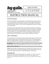
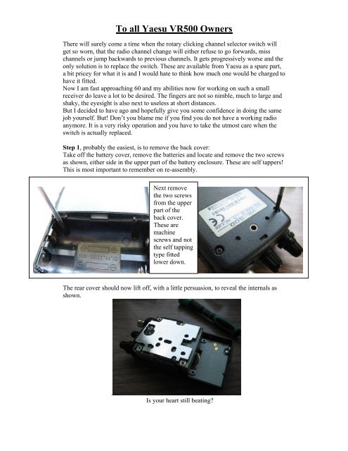
To all Yaesu <strong>VR</strong><strong>500</strong> OwnersThere will surely come a time when the rotary clicking channel selector <strong>switch</strong> willget so worn, that the radio channel change will either refuse to go forwards, misschannels or jump backwards to previous channels. It gets progressively worse and theonly solution is to replace the <strong>switch</strong>. These are available from Yaesu as a spare part,a bit pricey for what it is and I would hate to think how much one would be charged tohave it fitted.Now I am fast approaching 60 and my abilities now for working on such a smallreceiver do leave a lot to be desired. The fingers are not so nimble, much to large andshaky, the eyesight is also next to useless at short distances.But I decided to have ago and hopefully give you some confidence in doing the samejob yourself. But! Don’t you blame me if you find you do not have a working radioanymore. It is a very risky operation and you have to take the utmost care when the<strong>switch</strong> is actually replaced.Step 1, probably the easiest, is to remove the back cover:Take off the battery cover, remove the batteries and locate and remove the two screwsas shown, either side in the upper part of the battery enclosure. These are self tappers!This is most important to remember on re-assembly.Next removethe two screwsfrom the upperpart of theback cover.These aremachinescrews and notthe self tappingtype fittedlower down.The rear cover should now lift off, with a little persuasion, to reveal the internals asshown..Is your heart still beating?
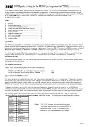
Next you have to remove the knobs, first pull off the small channel/freq change knob.Then thelower onethat does thesquelch.Next theVolume knobpulls offfollowed bythe rubber sealaround theBNC/Antennaconnector.Next is the removal of the small seal that is under the now removed volume knob.Now the first of the tricky operations starts. This is theremoval of three circular fixing nuts that are located underthe three items just visited. I did not have the specialspanner required for these but the photo on the left gives aclue as to how I removed the fixings. A pair of thin longnosed pliers were used to engage in the slots of the ringsand to enable the rings to be unscrewed, normalanticlockwise rotation to remove. The YELLOW arrow isone of the unscrewing slots, the RED arrows show thecutaways that allow the ring to slip over the BNC socket.
Next remove the two small screws holding the keypad board at the bottom of the case.With these fittings removed, it should now be possibleto remove the remaining half of the plastic caseincluding the loudspeaker. As this was my firstattempt I accidentally removed some board fixingscrews that did not need removal until the next step.However, it did not make any real difference and Iwill show these being removed prior to case removaljust for keeping continuity in the photographs.If you have already removed the case then removingthese next three screws is your next step.The last photo is where you should be now, put the case and rubber seal/<strong>switch</strong> covers safely to one side.
Remove the funny flat head screw locatedclose to the offending channel <strong>switch</strong>.Now you will need the soldering iron tounsolder at three locations. These are at twochassis earth points and the antenna inputfrom the BNC socket center terminal.The latter is unsoldered at the board andNOT at the BNC socket.This upper board can now be lifted up andaway to reveal a second board beneath. Nowwe have to remove another three screws forthis board, which once done, will allow theboard to be removed by sliding to the right(as viewed on the photos) and slightlyupwards. It is easier to do than to describe!1 st Screw 2 nd Screw
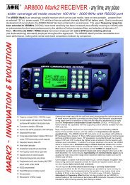
3 rd Screw Pull board up to disengage the white rectangularconnector then slide right and upwards to clear. frame.Left is another view of THE NASTY!Still a bit to do yet before we can extract itand the going gets really tough from now on.We have to remove the metal frame afterfirst removing the LCD metal escutcheon.When this is removed, the LCD is hangingperilously by three small wires on one side.The LCD must therefore be treated withutmost care to ensure minimum displacementuntil we get it all back together again. Theescutcheon is removed by carefully bendingback its securing tabs.Escutcheon removed.1 st metal frame fixing screw.2 nd metal frame fixing screw. Frame removed.
How did I get the little XXX out? Well I laid the whole soldering iron bit across allsix solder pads of the <strong>switch</strong> and melted them all at once. At the same time I wasapplying pressure to make the <strong>switch</strong> let go of the board but also making sure the irondid not destroy the LCD!I wish I had had an assistant to help me but somehow I managed to do it.I also figured I could clean the board up afterwards and when the <strong>switch</strong> had beenremoved, I found it easier to solder suck from the other side of the board, that is the<strong>switch</strong> body side.I cannot stress too much the need for minimum movement of the LCD. Just raise itgently to give sufficient access for the soldering iron bit and NO MORE!It may be helpful to slightly trim the tags of the new <strong>switch</strong> before fitting. The reasonfor this is that the new <strong>switch</strong> has slightly longer tags than the old one removed. If youdo not trim the tags, they will stop the LCD setting down in its correct position. If youleave them long you will find it difficult to trim the tags without lifting the LCDdisplay and this should be avoided as much as possible.Re-assembly is of course the reverse of above instructions and don’t forget to resolderthe BNC and earthing points.The rubber seals are a bit tricky to get back but not too difficult.