All-Optical Demultiplexing of Quaternary Amplitude-Shift Keying ...
All-Optical Demultiplexing of Quaternary Amplitude-Shift Keying ...
All-Optical Demultiplexing of Quaternary Amplitude-Shift Keying ...
- No tags were found...

You also want an ePaper? Increase the reach of your titles
YUMPU automatically turns print PDFs into web optimized ePapers that Google loves.
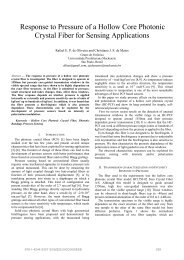
<strong>All</strong>-<strong>Optical</strong> <strong>Demultiplexing</strong> <strong>of</strong> <strong>Quaternary</strong><strong>Amplitude</strong>-<strong>Shift</strong> <strong>Keying</strong> Signals with Fiber-BasedFour-Wave Mixing <strong>Optical</strong> GatesE. A. M. Fagotto and M. L. F. AbbadeSchool <strong>of</strong> Electrical EngineeringPUC-CampinasCampinas, SP Brazileric@puc-campinas.edu.br, abbade@puc-campinas.edu.brAuthorsAbstract— In this work we present, and test by simulations, anall-optical demultiplexing technique for quaternary amplitudeshiftkeying signals that employs fiber-based four wave mixingoptical gates. Results suggest this technique may be suitable to beapplied in metropolitan area networks that transmit quaternaryamplitude optical packets allowing for all-optical operations aslabel reading and label swapping in a network node.Keywords ⎯ demultiplexing, multilevel signal, optical gates,four-wave mixing, transfer function, optical packets.OI. INTRODUCTIONne <strong>of</strong> the main reasons for all-optical signal processingto be extensively researched is that it avoids thebottleneck due to optical-electrical and electrical-opticalconversions in telecommunications networks. Packet routingschemes and conversion between modulation formats areincluded in this trend [1, 2] and, furthermore, there are manystrategies to generate optical packets. Among them, aquaternary amplitude-shift keying (4ASK) signal can serve asa quaternary amplitude optical packet (QAOP), carrying thelabel and the payload data simultaneously in a same carrier [3,4]. To route these QAOPs, it is necessary to demultiplex the4ASK signal to read the binary signal that stands for the labeldata when the QAOP reaches an intermediary network nodebefore being forwarded to its destination. In this work, weshow this demultiplexing can be accomplished with four-wavemixing optical gates (FWM-OGs) implemented in highly nonlineardispersion shifted fibers (HNL-DSF). Section II reviewsthe basics <strong>of</strong> QAOPs. In Section III the design <strong>of</strong> FWM-OGsand their usage for demultiplexing 4ASK signals is outlined.In Section IV the simulation results are shown and discussed.Finally, our conclusions and the perspectives <strong>of</strong> this work arepresented in Section V.II. QUATERNARY AMPLITUDE OPTICAL PACKETSThe use <strong>of</strong> a 4ASK signal as QAOP was proposed in [5] andtested over the FAPESP-KyaTera network in [6]. The basicidea is to code the label and payload information into a samedibit, that is, one bit representing the label and the other onethe payload. Since there are four possibilities, 00, 01, 10 and11, the physical implementation can be accomplished using a4ASK signal. Fig. 1(a) shows the eye diagram for a 4ASKsignal detected in back-to-back configuration and (b) afterpropagating 20 km over the KyaTera network. The powerlevels correspondence with the dibits is also displayed in Fig.1(a), where the leftmost bit represents the payload data and theother one the label.(a)(b)1 1010100Fig. 1: (a) Eye diagram for a 4ASK signal detected in back-to-backconfiguration and (b) after propagating 20 km over the KyaTera network. In(a) it is shown the correspondence between the dibits and the power levels,being the leftmost bit the payload and the other one the label.978-1-4244-5357-3/09/$26.00©2009IEEE 423
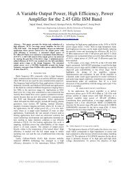
III. DEMULTIPLEXING OF QUATERNARY AMPLITUDE OPTICALPACKETS WITH OPTICAL GATESQAOPs seem to be a very interesting approach to all-opticalnetworking, since they carry simultaneously the label and thepayload data in the same bandwidth; besides they are lesssensitive to transmission nonlinearities than other techniques[5]. However, until now there has not be an all-opticaltechnique that allowed for to retrieve the label when theQAOP reached an intermediate network node, an operationrequired to forward the packet to its destination. Similarly, itmay be necessary to read the payload for label swapping. Toperform such operations in the optical domain, we introduce astrategy that employs two types <strong>of</strong> fiber-based OGs withdifferent optical power transfer functions (TFs) to demultiplexthe 4ASK signal. The first type has an S-shaped TF (S-TF),which will map the first and the second input power levels intoan output level A and the third and fourth levels into an outputlevel B (Fig. 2(a)). The second type has a U-shaped TF (U-TF)that will map the first and the third input power levels into alower output level A and the second and the fourth levels intoa higher power output level B (Fig. 2(b)). These OGs can beimplemented using two stages <strong>of</strong> serially coupled HNL-DSFs(Figs 3(a) and (b)). In the first stage, the 4ASK signal, atcarrier frequency f D , will co-propagate along with a pumpsignal CW 1 , at frequency f CW1 , and four-wave mixing (FWM)will take place between them. An optical band-pass filter(OBPF) permits to select the FWM product atfrequency f1 = 2 f D− f at the fiber output. This selected+ CW 1signal will be coupled to the second HNL-DSF stage and itwill co-propagate with the pump signal CW 2 , at frequencyf CW2 , generating FWM products and, similarly as done in thefirst stage, we will set the OBPF to select the signal atfrequency f2= 2 f1− f . A valuable insight can be+ + CW 2<strong>of</strong>fered by a simplified description <strong>of</strong> the FWM effect inD e m ultip le x e dD a ta(a)D e m u ltip le x e dd a ta(b )P ou tP ou t0 01 04A S Ksig n alA0 0AS Tra n sf er F u nc tionB0 11 1P inU T ran s fe r F un c tio n1 04A S Ksig n alFig. 2: Scheme <strong>of</strong> the 4ASK signal demultiplexing (a) via S-TF and (b) withU-TF.B0 11 1P inFig. 3: (a) Detail <strong>of</strong> an single-stage FWM OG and (b)a two-stage FWM OG.optical fibers [7]:P+= ηγ2 2⎡1expP PCWexp( −αL)( −αL) 2− ⎤, (1)D ⎢⎣ α ⎥ ⎦where P+, PDand PCWare, respectively, the powers carriedby the FWM product at f , by the data and the CW pump+signals.γ and α are, respectively, the nonlinear and theattenuation fiber indexes, L is the fiber length. The efficiencyη é :and2( − αL) sin ( ∆κ' L / 2)[ 1−exp( − αL)] ⎭ ⎬⎫2= α ⎧ 4expη ⎨1+, (2)2 2α + ∆κ' ⎩2( −αL)⎡1−exp ⎤ef∆κ' = ∆κ+ γ ( 2PD− PCW) ⎢⎥ , (3)⎢⎣αLef⎥⎦22πc2∆κ ≅ S0( λ)( fD− fCW) ( fD− f0) , (4)f4D[ 1−exp( − )] ,αLL ef= (5)Lλ0is the fiber zero-dispersion wavelength, S 0 the dispersionslope, fCWand fDthe pump and data signal frequencies, ∆κand ∆κ’ are, respectively, the independent and dependentphase-mismatch factors. Equation (1) holds well if self- andcross-phase modulation are negligible as well data and pumpsignal depletions. Besides, the signals wavelengths should notbe farther than 10 nm from λ0[8]. By inspecting (1), one can2009 SBMO/IEEE MTT-S International Microwave & Optoelectronics Conference (IMOC 2009) 424
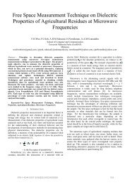
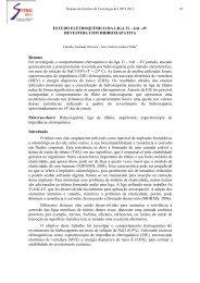
notice that ifPDtends to zero it also makes P+goes to zero .Furthermore, in the event <strong>of</strong> FWM saturation, PDwill tend toa constant for high enough values <strong>of</strong> PDif ∆κ’L ≈ π. Thisbrief discussion, although a qualitative one, makes possible tounderstand how the FWM effect may account for the step-likepr<strong>of</strong>ile <strong>of</strong> the S and U-TFs presented in Section III.IV. SIMULATION RESULTS AND DISCUSSIONThe OGs TFs were designed using a heuristic calculationmethod that will be detailed in a future publication [9]. Usingthis method, we found the S- and U-TFs OGs parameterslisted in Table I for the devices that will demultiplex a 4-ASKsignal whose carrier wavelength is set at 1554.5 nm. The 4-ASK signal power levels are δ 0 = 0, δ 1 = 0.49 mW, δ 2 = 1.40mW and δ 3 = 1.97 mW (Fig. 4). In Table I, G is the erbiumdoped fiber amplifier gain and the pump power is 1 mW,λ = 1557 nm and α = 0.2 dB/km for any FWM- OG . For0the simulations <strong>of</strong> demutiplexing, we coded the label and thepayload data into a 4ASK signal that was used to modulate thetransmitter, with the first bit <strong>of</strong> the dibit representing thepayload and the second bit standing for the label as illustratedin Section III (Fig 2).TABLE I – OGs ParametersS-TF-OG U-TF-OG1st 2nd stage 1st stage 2nd stagestageL (m) 3600 3100 4560 4300S 0 (ps/nm 2 /km) 0.04 0.03 0.03 0.03γ ((W.km) -1 ) 12 12 15 12f CW (THz) 1557.53 1555.02 1557.53 1555.02G (dB) 13.35 25.65 13.43 25.00In Fig. 5 are the TFs corresponding to the S- (Fig. 5(a)) and U-TF (Fig 5(b)), both calculated using the parameters showed inTable I. These OG TFs were tailored to “fit into” thequaternary signal levels, what can be checked out by justcomparing them to the 4-ASK signal in Fig. 4. The S-TF firststep “contains” the first and the second 4-ASK levels and itssecond step “accommodates” the third and the fourthquaternary signal levels. In turn, each U-TF step or peak“contains” just one 4-ASK signal level. Therefore, the labeldata can be demultiplexed utilizing an S-TF OG and thepayload by means <strong>of</strong> a U-TF OG. For our tests, the labelcontained 2048 bit transmitted at 2.5 Gb/s and the payload8192 bit at 10.0 Gb/s. The transmission was carried out throughlinks <strong>of</strong> 50 km <strong>of</strong> standard fiber coupled to 8.89 km <strong>of</strong>dispersion compensation fiber (DCF). In Fig. 6, we show theeye-diagrams <strong>of</strong> the retrieved binary signals corresponding tothe label (a) when detected in back-to-back configuration and(b) after propagating 150 km. For their demultiplexing an S-TFOG was utilized. The eye-diagrams in Fig. 7 stand for thedemultiplexed and then detected binary signals that representthe payload (a) in back-to-back configuration and (b) also aftera 150 km propagation. The demultiplexing operation wascarried out with a U-TF OG. We evaluated the bit error rates(BERs) considering the noise distribution is Gaussian and wefound their BERs are error-free, that is, they are less than 10 -15 .However, although the demultiplexed signals correspondent tothe payload and label have BERs that are error free, there is anevident difference between the eye-diagrams qualities <strong>of</strong> thesignals retrieved whether with S- or U-TF OGs. The mainreason for such a difference relies on the TF pr<strong>of</strong>iles. The S-TFis the standard optical TF <strong>of</strong> optical regenerators and, therefore,it accounts for the high quality <strong>of</strong> signals demultiplexed with S-TF OGs. Furthermore, the implemented U-TF has “rounded”peaks, instead <strong>of</strong> flat tops (see Fig.2), which cause the jitterobserved in Fig. 7, although, within the simulated distances, thesignal degradation is not significant. Because <strong>of</strong> these results,since demultiplexed signals BERs are error-free afterpropagating through distances typical <strong>of</strong> metropolitan areaOutput Signal <strong>Optical</strong> Power (mW)1,00,80,60,40,20,01,00,80,60,40,20,0Signal <strong>Optical</strong> Power (mW)(a)2.01.51.0(b)0.500 0.10 0.15 0.20 0.25Time(ns)Fig. 4: Eye-diagram <strong>of</strong> the 4-ASK signal optical power used in simulations totest the demultiplexing with FWM OGs.0,0 0,5 1,0 1,5 2,0 2,5Input Signal <strong>Optical</strong> Power (mW)Fig.5: OG TFs calculated as parameters in Table I. (a) S-TF and (b) U-TF2009 SBMO/IEEE MTT-S International Microwave & Optoelectronics Conference (IMOC 2009) 425
networks (MANs), we understand there is good evidence thatthe demultiplexing technique presented in this work may beutilized in QAOPs networks for all-optical operations such aslabel reading and label swapping.Electrical Signal (A.U.)0.2(a)(b)0.4 0.6 0.8 1.0Time(ns)Fig.6: Binary signals demultiplexed with an S-TF OG and representing thelabel data. (a) Back-to-back and (b) after propagating 150 km.Electrical Signal (A.U.)0.0(a)(b)0.10 0.15 0.20 0.25Time(ns)the BERs <strong>of</strong> the demultiplexed binary signals are error-freewithin typical distances <strong>of</strong> MANs. Since a 4ASK signal canserve as a QAOP[6], carrying simultaneously and in the samebandwidth the label and the payload data, our technique maybe utilized in QAOPs networks for all-optical operations suchas label reading and label swaping. Besides retrieving a binarysignal from a 4ASK signal, S-TF OGs have other extremelyinteresting feature, that is, they also regenerate thedemultiplexed signals. Finally, although in this work we justdiscussed fiber-based OGs, we expect the samedemultiplexing FWM technique works both in Bismuth oxidefibers [10] and in Silicon Photonics devices [11].ACKNOWLEDGEMENTSThis work was supported by FAPESP under grant 03/08320-2.REFERENCES[1] G.T. Zhou Zhou, G.T. Xu, K. Wu, J. Cishuo Yan Yikai Su Lin, J.T.,"Self-pumping wavelength conversion for DPSK signals and DQPSKgeneration through four-wave mixing in highly nonlinear optical fiber", IEEEPhoton. Technol. Lett. vol 18, no. 22, pp. 2389-2391, 2005.[2] D. J. Blumenthal, A. Carena, L. Rau, V. Curri, and S. Humphries, “<strong>All</strong>opticallabel swapping with wavelength conversion for WDM-IP networkswith subcarrier multiplexed addressing,” IEEE Photon. Technol. Lett., vol. 11,pp. 1497–1499, Aug. 1999.[3] M. L. F. Abbade, E. A. M. Fagotto, R. S. Braga, F. R. Barbosa, E.Moschim, and I. E. Fonseca, “<strong>Quaternary</strong> <strong>Optical</strong> Packets Generated by FiberFour-Wave Mixing,” IEEE Photon. Technol. Lett., vol.. 18, no. 2, p. 331-333,2006.[4] N. Chi, L. Xu, L. Christiansen, K. Yvind, J. Zhang, P. Holm-Nielsen, C.Peucheret, C. Zhang and P. Jeppesen, “<strong>Optical</strong> label swapping and packettransmission based on ASK/DPSK orthogonal modulation format in IP-over-WDM networks,”in <strong>Optical</strong> Fiber Communication Conf. 2003, pp. 792–794.[5] M.L.F. Abbade, E.A.M. Fagotto, R.S. Braga, I.E. Fonseca, E. Moschimand F.R. Barbosa,” <strong>Optical</strong> <strong>Amplitude</strong> Multiplexing through Four-WaveMixing in <strong>Optical</strong> Fibers IEEE Phot. Tech. Lett., vol. 17, pp. 151-153, 2005.[6] M. L. F. Abbade , Almeida, F.P. , F. G. G. Branquinho , E. A. M. Fagotto ,R. S. Braga , F. A. Callegari , M. L. Rocha , S. M. Rossi , J.M.C. Boggio , H.L. Fragnito,” <strong>Optical</strong>ly Generated <strong>Quaternary</strong> Packets: Transmission over theKyaTera Network,” in: IEEE Laser and Electro Optics Society Annual,Montreal. IEEE Laser and Electro Optics Society Annual 2006.[7] A. Bogris, D. Syvridis, “Regenerative Properties <strong>of</strong> a Pump -ModulatedFour Wave Mixing Scheme in Dispersion <strong>Shift</strong>ed Fibers”, J. Lightwave Tech.,vol. 21, no 9, Sept 2003.[8] K. Inoue, “Four-wave mixing in optical fiber in the zero-dispersionwavelength region,” J. Lightwave Technol, vol. 10, pp. 1553-1561, Nov.1992.[9] E. A. M. Fagotto and M.L.F. Abbade, “Design <strong>of</strong> Fiber-Based <strong>Optical</strong>Gates for <strong>Optical</strong> Signal Processing.”, unpublished.[10] Fok, M. P. and C. Shu, \Tunable dual-wavelength erbium-doped fiberlaser stabilized by four-wave mixing in a 35-cm highly nonlinear bismuthoxidefiber," Opt. Express, Vol. 15, No. 10, 5925-5930, 2007.[11] R. Salem, M. A. Foster, A. C. Turner, D. F. Geraghty, M. Lipson and A.L. Gaeta.,"Signal regeneration using low-power four-wave mixing on siliconchip", Nature Photon., vol.2 (1), pp.35-38, Jan. 2008.Fig.7: Binary signals demultiplexed with a U-TF OG and representing thepayload data. (a) Back-to-back and (b) after propagating 150 km.V. CONCLUSIONIn this work we presented and tested by simulations an allopticaldemultiplexing technique for 4ASK signals thatemploys FWM fiber-based OGs. Our calculations show that2009 SBMO/IEEE MTT-S International Microwave & Optoelectronics Conference (IMOC 2009) 426