Excel Based Finite Difference Modeling of Ground Water Flow
Excel Based Finite Difference Modeling of Ground Water Flow
Excel Based Finite Difference Modeling of Ground Water Flow
- No tags were found...

Create successful ePaper yourself
Turn your PDF publications into a flip-book with our unique Google optimized e-Paper software.
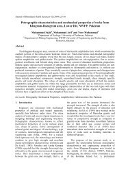
This is Laplace’s equation which governs the flow<strong>of</strong> groundwater through an isotropic, homogeneousaquifer under steady state conditions. This equationsimply states that the sum <strong>of</strong> partial derivates <strong>of</strong> head(h) with respect to x, y, and z is zero. The solution <strong>of</strong>Laplace’s equation requires specification <strong>of</strong> boundaryconditions such as Dirichlet conditions and Neumannconditions (Neuman, 1973). As currently we aredealing with ground water flow in two dimensionstherefore the Laplace’s equation reduces to2 2h h0 …………...(4)2 2x yFig. 1.<strong>Finite</strong> difference grid <strong>of</strong> nodes.Now consider a regularly spaced grid <strong>of</strong> nodesrepresented by i columns and j rows and horizontally andvertically spaced by distances x and y respectivelyas shown in figure 1. The head at node i ,j is h ,.2h2x2h2yhhi 1, ji,j 12hi,j( x)2h(2i,jy)2hhi 1, ji,j 1i jAdding these two terms according to Laplace’sequation and considering x y for a square gridwe haveh h h h h 0 …(5)i 1,j i 1, j i,j 1 i,j 14 i,jThe above equation is the most widely usedequation in finite difference solutions <strong>of</strong> steady-stateflow problems and forms the heart <strong>of</strong> this program. It isiteratively used in the form <strong>of</strong> a kernel or Laplacianoperator for computation <strong>of</strong> heads at each node in thegrid. Such operators are also used in satellite imageprocessing for edge detection and image smoothing (El-Sheimy et al., 2005).3. Working procedureThe complete working procedure <strong>of</strong> the presentedmodeling template is given in Figure 2. Full details forusing this template are given as a help worksheet in the<strong>Excel</strong> <strong>Modeling</strong> file. To design a new model the usersimply needs to copy and paste the required samplecells into the design region <strong>of</strong> the template (Fig. 3)according to the shape, size and type <strong>of</strong> boundaries thatdefine the aquifer. The values for constant head nodesat the boundaries are also defined.If required the iteration parameters; Maximumiterations (default 100) and Maximum change (default.001) are set using the <strong>Excel</strong> menu; Tools > Options >Calculation Tab. During each iteration the value <strong>of</strong>heads at all nodes are calculated. The program keeps oniterating unless convergence occurs i.e. the absolutedifference in heads at each node from previous andcurrent iteration is less than the Maximum changevalue.This parameter is <strong>of</strong>ten critical to the modelingprocess. Too large a value will degrade the finalsolution, because convergence will not really haveoccurred. Too small a value will lead to very longexecution times and <strong>of</strong>ten result in no convergencebecause computational errors may cause thedifference in heads to remain larger than theMaximum change parameter. For this purpose theMaximum iteration value is also given so that theprogram does not enter into an infinite iterative loop.Thus iterations stop when conditions for either <strong>of</strong>these two parameters are satisfied. Now to start theiterative process the user simply needs to press F9key. The values in each cell representing a grid nodewill keep on changing unless convergence occurs anda steady state flow is attained.The modeled head values for the grid nodes can besaved as a XYZ file (X, Y are columns, rows and Z ishead) using the Visual Basic for Applications macro. Itis activated by pressing Ctrl-S keys for entering theoutput filename. The output file can be used by Surferor any other contouring s<strong>of</strong>tware for girding andsubsequent contouring or surface generation. The finalcontour map represents the variation <strong>of</strong> head in themodeled region, where flow lines are considered to bemoving perpendicular to the contour lines from higherto lower potential.Simulation results <strong>of</strong> this spreadsheet can beutilized in different commercial s<strong>of</strong>tware’s likePROCESSING MODFLOW (Chiang and Kinzelbach,1998) etc. to develop a complete numerical groundwater model.50