dmc95 contact retention test tool kit - Daniels Manufacturing ...
dmc95 contact retention test tool kit - Daniels Manufacturing ...
dmc95 contact retention test tool kit - Daniels Manufacturing ...
- No tags were found...

Create successful ePaper yourself
Turn your PDF publications into a flip-book with our unique Google optimized e-Paper software.
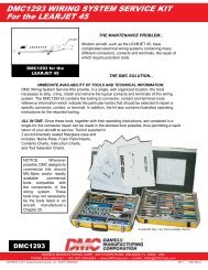
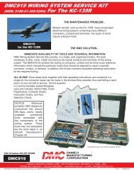
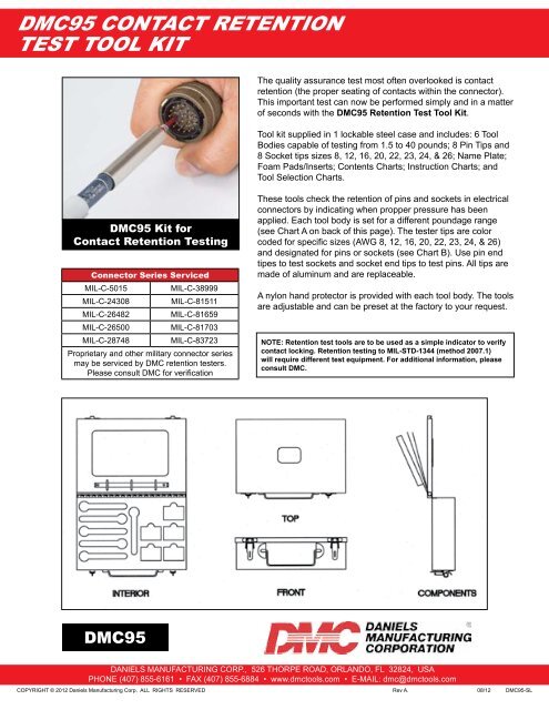
DMC95 CONTACT RETENTIONTEST TOOL KITThe quality assurance <strong>test</strong> most often overlooked is <strong>contact</strong><strong>retention</strong> (the proper seating of <strong>contact</strong>s within the connector).This important <strong>test</strong> can now be performed simply and in a matterof seconds with the DMC95 Retention Test Tool Kit.Tool <strong>kit</strong> supplied in 1 lockable steel case and includes: 6 ToolBodies capable of <strong>test</strong>ing from 1.5 to 40 pounds; 8 Pin Tips and8 Socket tips sizes 8, 12, 16, 20, 22, 23, 24, & 26; Name Plate;Foam Pads/Inserts; Contents Charts; Instruction Charts; andTool Selection Charts.DMC95 Kit forContact Retention TestingConnector Series ServicedMIL-C-5015MIL-C-38999MIL-C-24308MIL-C-81511MIL-C-26482MIL-C-81659MIL-C-26500MIL-C-81703MIL-C-28748MIL-C-83723Proprietary and other military connector seriesmay be serviced by DMC <strong>retention</strong> <strong>test</strong>ers.Please consult DMC for verificationThese <strong>tool</strong>s check the <strong>retention</strong> of pins and sockets in electricalconnectors by indicating when propper pressure has beenapplied. Each <strong>tool</strong> body is set for a different poundage range(see Chart A on back of this page). The <strong>test</strong>er tips are colorcoded for specific sizes (AWG 8, 12, 16, 20, 22, 23, 24, & 26)and designated for pins or sockets (see Chart B). Use pin endtipes to <strong>test</strong> sockets and socket end tips to <strong>test</strong> pins. All tips aremade of aluminum and are replaceable.A nylon hand protector is provided with each <strong>tool</strong> body. The <strong>tool</strong>sare adjustable and can be preset at the factory to your request.NOTE: Retention <strong>test</strong> <strong>tool</strong>s are to be used as a simple indicator to verify<strong>contact</strong> locking. Retention <strong>test</strong>ing to MIL-STD-1344 (method 2007.1)will require different <strong>test</strong> equipment. For additional information, pleaseconsult DMC.DMC95DANIELS MANUFACTURING CORP., 526 THORPE ROAD, ORLANDO, FL 32824, USAPHONE (407) 855-6161 • FAX (407) 855-6884 • www.dmc<strong>tool</strong>s.com • E-MAIL: dmc@dmc<strong>tool</strong>s.comCOPYRIGHT © 2012 <strong>Daniels</strong> <strong>Manufacturing</strong> Corp. ALL RIGHTS RESERVEDRev A. 08/12 DMC95-SL
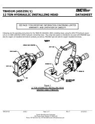
DMC95 CONTACT RETENTIONTEST TOOL KITHT250 ADJUSTABLE RETENTION TEST TOOLTOOL SET UP1. Tool part number designates <strong>tool</strong> body only, withouttip. Refer to Chart A for preset range of <strong>tool</strong>.2. Remove button head (shipping) screw. Selectappropriate tip and screw into <strong>tool</strong> body through slide.Refer to Chart B for tip part numbers.USE OF TOOL1. To <strong>test</strong> <strong>retention</strong> of socket <strong>contact</strong>s, use socket <strong>test</strong>ertip with preset <strong>tool</strong>. Insert <strong>test</strong>er (pin) into mating end of<strong>contact</strong>. Tool must be in a straight line with <strong>contact</strong>. Forpin <strong>contact</strong>s, fit pin <strong>test</strong>er to <strong>tool</strong> body and place over<strong>contact</strong> at the mating end.2. Apply pressure toward <strong>contact</strong> until slide aligns withindicator mark, <strong>contact</strong> should remain firmly in place.CHART AHandle P/N* Range LBS.HT250-1 1.5 THRU 3.0HT250-2 3.2 THRU 5.5HT250-3 4.0 THRU 8.0HT250-4 7.0 THRU 18.0HT250-5 17.0 THRU 25.0HT250-6 24.0 THRU 40.0CONTACTSIZECHART B - TIP PART NUMBERSCOLORCODESOCKETTESTERPINTESTER8 RED 67-008-01 68-008-0112 YELLOW 67-012-01 68-012-0116 BLUE 67-016-01 68-016-0120 RED 67-020-01 68-020-0122, 22M, 22D COPPER 67-022-01 68-022-0123 BLACK 67-023-01 68-023-0124 GOLD 67-024-01 68-024-0126 GREEN 67-026-01 68-026-01DANIELS MANUFACTURING CORP., 526 THORPE ROAD, ORLANDO, FL 32824, USAPHONE (407) 855-6161 • FAX (407) 855-6884 • www.dmc<strong>tool</strong>s.com • E-MAIL: dmc@dmc<strong>tool</strong>s.comCOPYRIGHT © 2012 <strong>Daniels</strong> <strong>Manufacturing</strong> Corp. ALL RIGHTS RESERVEDTOOL ADJUSTMENT1. Remove hand protector, back off lock nut away frombody of <strong>tool</strong> to allow free movement of adjustment screw.2. Secure <strong>tool</strong> in RTCG-75 or equivalent setting gage forprecise calibration. If precise calibration isn’t required,you can set the <strong>tool</strong> by holding the <strong>tool</strong> firmly by hand ona scale or other weight indicating device, and apply axialforce until the end of the slide is aligned with the indicatormark. Note reading of force on gage (or accurate weightscale).3. Adjust <strong>tool</strong> to required force by turning adjustmentscrew with a screwdriver, clockwise to increase forceand counterclockwise to decrease force. When requiredvalue is achieved, tighten lock nut firmly while maintainingalignment of slide and indicator line. Tool is now set.4. Note: Inspection stickers may be used to seal handprotector onto <strong>tool</strong> body, in order to signal any tamperingwith the adjustment screw.Rev A. 08/12 DMC95-SL