Variable Displacement Pump A4VG - Group VH A/S
Variable Displacement Pump A4VG - Group VH A/S
Variable Displacement Pump A4VG - Group VH A/S

Create successful ePaper yourself
Turn your PDF publications into a flip-book with our unique Google optimized e-Paper software.
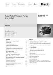
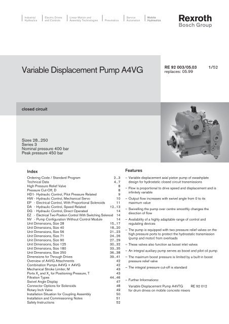
IndustrialHydraulicsElectric Drivesand ControlsLinear Motion andAssembly TechnologiesPneumaticsServiceAutomationMobileHydraulics<strong>Variable</strong> <strong>Displacement</strong> <strong>Pump</strong> <strong>A4VG</strong>RE 92 003/05.03 1/52replaces: 05.99closed circuitSizes 28...250Series 3Nominal pressure 400 barPeak pressure 450 barIndexOrdering Code / Standard Program 2...3Technical Data 4...7High Pressure Relief Valve 8Pressure Cut-Off, D 8HD1- Hydraulic Control, Pilot Pressure Related 9HW - Hydraulic Control, Mechanical Servo 10EP - Electrical Control, With Proportional Solenoids 11DA - Hydraulic Control, Speed Related 12...13DG - Hydraulic Control, Direct Operated 14EZ - Electrical Two-Position Control With Switching Solenoid 14NV - <strong>Pump</strong> Configuration Without Control Module 14Unit Dimensions, Size 28 15...17Unit Dimensions, Size 40 18...20Unit Dimensions, Size 56 21...23Unit Dimensions, Size 71 24...26Unit Dimensions, Size 90 27...29Unit Dimensions, Size 125 30...32Unit Dimensions, Size 180 33...35Unit Dimensions, Size 250 36...38Dimensions for Through Drives 39...41Overview of <strong>A4VG</strong> Attachments 42Combination <strong>Pump</strong>s <strong>A4VG</strong> + <strong>A4VG</strong> 42Mechanical Stroke Limiter, M 43Ports X 3and X 4for Positioning Pressure, T 43Filtration Types 44...46Swivel Angle Display 47Connector Options for Solenoids 48Rotary Inch Valve 49Installation Situation for Coupling Assembly 50Installation and Commissioning Notes 51Safety Instructions 52Features– <strong>Variable</strong> displacement axial piston pump of swashplatedesign for hydrostatic closed circuit transmissions– Flow is proportional to drive speed and displacement and isinfinitely variable– Output flow increases with swivel angle from 0 to itsmaximum value– Swivelling the pump over centre smoothly changes thedirection of flow– Availability of a highly adaptable range of control andregulating devices– The pump is equipped with two pressure relief valves on thehigh pressure ports to protect the hydrostatic transmission(pump and motor) from overloads– These valves also function as boost inlet valves– An integral auxiliary pump serves as boost and pilot oil pump– The maximum boost pressure is limited by a built-in boostpressure relief valve– The integral pressure cut-off is standard– Further Informations:<strong>Variable</strong> <strong>Displacement</strong> <strong>Pump</strong> A4VTG RE 92 012for drum drives on mobile concrete mixers
2/52 Bosch Rexroth AG | Mobile Hydraulics <strong>A4VG</strong> | RE 92 003/05.03Ordering Code / Standard ProgrammAxial piston unit<strong>Variable</strong> swashplate design, nominal pressure 400 bar, peak pressure 450 barOperation<strong>Pump</strong> in closed circuitsSize<strong>Displacement</strong> V g max in cm 3 28 40 56 71 90 125 180 250Control device 28 40 56 71 90 125 180 250without control module NV N<strong>VH</strong>ydraulic control, pilot pressure related HD1 HD1Hydraulic control, mechanical servo HW HWHydraulic control, speed related DA DAHydraulic control, direct operated DG DGElectrical two-position control with switching solenoid EZ EZElectrical control with proportional solenoid EP EPSolenoid voltage (only for EP, EZ or DA)U = 12 V 1U = 24 V 2Pressure cut-offwith pressure cut-off (standard)Neutral position switch (only for HW)without neutral position switch (no code)with neutral position switchMechanical stroke limiterwithout mechanical stroke limiter (no code)with mechanical stroke limiter, external adjustablePorts X 3, X 4for positioning pressurewithout ports X 3 , X 4 (no code)with ports X 3 , X 4DA control valve NV EZ DG EP HW HD1 DA 28…250without DA control valve – 1with DA control valve, fixed setting – – 2with DA control valve, mech adjust. with control lever L – – 3LR – – 3Rwith DA control valve, fixed setting and hydraulic inchvalve built-on, control with brake fluid– – – – – – 4with DA control valve, mech. adjust. with control lever and L – – – – – – 5Lhydraulic inch valve built-on, control with brake fluid R – – – – – – 5Rwith DA control valve, fixed setting,and connections for master controller– – 7with DA control valve, fixed setting and hydraulic inchvalve built-on, control with mineral oil– – – – – – 8with DA control valve, mech. adjust. with control lever and L – – – – – – 9Lhydraulic inch valve built-on, control with mineral oil R – – – – – – 9RDA control valve with control leverwithout control lever (no code)with control lever - anti-clockwise operation directionwith control lever - clockwise operation directionLRSeriesSeries 3, Index 2 32Direction of rotation 28…250viewed on shaft end clockwise Ranti-clockwiseLSealsNBR (nitrile-caoutchouc), shaft seal in FKM (fluor-caoutchouc)Shaft end (permissible input torque see page 7) 28 40 56 71 90 125 180 250splined shaft for single pump ZDIN 5480 for combination pump -1st pump – 1 ) – 1 ) – 1 ) Asplined shaft for single pump SANSI B92.1a–1976 for combination pump -1st pump – 2 ) – 2 ) – 2 ) Tonly for combination pump - 2nd pump – – – – – – U<strong>A4VG</strong>DLMTN
RE 92 003/05.03 | <strong>A4VG</strong> Mobile Hydraulics | Bosch Rexroth AG 3/52Axial piston unitOperationSizeControl deviceSeriesDirection of rotationSealsShaft endA4V G / 3 2 – NMounting flange 28 40 56 71 90 125 180 250SAE J744 – 2-hole – – – – – CSAE J744 – 4-hole – – – – – – DSAE J744 – 2 + 4-hole – – – – – FService line connections 28 40...180 250Ports A and B SAE, (metric fastening thread), at side (on opposite sides) – – 02Ports A and B SAE, (metric fastening thread), at side (same side) – 10Auxiliary pump 28 40 56 71 90 125 180 250with integral auxiliary pump, without through driveF00without integral auxiliary pump, without through driveN00with integral auxiliary pump, with through driveF...without integral auxiliary pump, with through driveK...Through drive (for mounting options see page 39)Flange SAE J744 3 ) Splined shaft hub 28 40 56 71 90 125 180 25082-2(A) 5/8in 9T 16/32DP 4) ...01101-2(B) 7/8in 13T 16/32DP 4 ) ...021in 15T 16/32DP 4 ) ...04127-2(C) 1in 15T 16/32DP 4 ) – – – – – – – ...091 1/4in 14T 12/24DP 4 ) – – ...07152-2/4(D) W35 2x30x16x9g 5) – – – – – – – ...731 3/4in 13T 8/16DP 4) – – – – – ...69165-4(E) 1 3/4in 13T 8/16DP 4) – – – – – – ...72Valves Einstellbereich 28 40 56 71 90 125 180 250with high press. relief valve, pilot controlled 100...420 bar with bypass – – – 1with high pressure relief valve, 270...420 bar without bypass – – – – – 3direct controlled, (fixed setting) with bypass – – – – – 5100...250 bar without bypass – – – – – 4with bypass – – – – – 6Filtration 28 40 56 71 90 125 180 250Filtration in the suction line of the auxiliary (boost) pumpSFiltration in the pressure line of the auxiliary (boost) pump:ports for external boost circuit filter, (F e and F a )Dcold start valve and ports for external boost circuit filter, (F e and F a ) – – Kfilter built-on (supplied complete) 6 ) – – Ffilter built-on with contamination indicator, lamp and electr. signal 6 ) – – Mfilter built-on with contamination indicator, window 6 ) – – Pfilter built-on with contamination indicator, electr. signal 6 ) – – LExternal supply (model without integral auxiliary pump - N00, K..)ESwivel angle display 28 40 56 71 90 125 180 250without swivel angle display (no code)Electrical swivel angle sensorRRange of male connectors for solenoids (only for EP, EZ and DA) 28 40 56 71 90 125 180 250DEUTSCH male connector injection molded, 2-pin (without quenching diode)PDEUTSCH male connector injection molded, 2-pin(with bidirectional quenching diode) 7 )QDEUTSCH male connector with stranded wire, 2-pin (without quenching diode) 8 )TDIN male connector to Hirschmann (without quenching diode) 8 )H1) standard for combination pumps - 1st pump: shaft Z2) standard for combination pumps - 1st pump: shaft S3) 2 2-hole; 4 4-hole4) splined shaft hub to ANSI B92.1a-1976 (splined shaft allocation to SAE J744, see pages 39-41)5) splined shaft hub to DIN 54806) with cold start valve7) version with bidirectional quenching diode only for control device EZ and DA= preferred program8) not for new projects= available = available on request – = not available
4/52 Bosch Rexroth AG | Mobile Hydraulics <strong>A4VG</strong> | RE 92 003/05.03Technical DataFluidBefore starting a project, get detailed information about theselection of pressure fluids and application conditions from ourcatalog sheets RE 90220 (mineral oil), RE 90221(environmentally acceptable hydraulic fluids) and RE 90223(fire resistant hydraulic fluids, HF).The <strong>A4VG</strong> variable displacement pump is not suitable foroperation with HFA, HFB and HFC fluids. When operating withHFD or environmentally acceptable hydraulic fluids, obey therestrictions in the technical data and seal selection – pleasecontact us. The hydraulic fluid used should be stated in cleartext in the order.Operating viscosity rangeIn order to obtain optimum efficiency and service life, select theoperating viscosity (at operating temperature) from within therangeν opt = operating viscosity 16...36 mm 2 /sdepending on the circuit temperature (closed circuit).Viscosity limitsThe limiting values for viscosity are as follows:ν min = 5 mm 2 /sshort term (t < 3 min)at a max. permissible temp. of t max = +115°C.Ensure that the max. fluid temperature is also not exceeded inany pump space (for instance bearing area).ν max = 1600 mm 2 /sshort term (t < 3min)on cold start (p ≤ 30 bar, n ≤ 1000 rpm, t min = -40°C).At temperatures of -25°C down to -40°C special measures arerequired. Please contact us for further information.For detailed information on use at low temperatures, seeRE 90300-03-B.Notes on the selection of the hydraulic fluidIn order to select the correct fluid, it is necessary to know theoperating temperature in the circuit (closed circuit) in relationto the ambient temperature.The hydraulic fluid should be selected so that within theoperating temperature range, the operating viscosity lies withinthe optimum range (ν opt ) (see shaded section of belowselection diagram). We recommend to chose the higherpossible viscosity range.Example:At a circuit temperature of 60°C, the recommended operatingviscosity range is VG 46 or VG 68 (ν opt ; shaded area in belowselection diagram). VG 68 should then be selected.Important: The leakage oil (case drain oil) temperature isinfluenced by pressure and pump speed and is always higherthan the circuit temperature. However, the temperature mustnot exceed 115°C at no point in the circuit.If it is not possible to comply with the above conditionsbecause of extreme operating parameters or high ambienttemperatures please consult us.Selection diagramviscosity ν in mm 2 /s2500-40° -20° 0° 20° 40° 60° 80° 100°1600100060040020010060402010VG 22VG 32VG 68VG 46VG 10016003616ν opt.55-40° -25° -10° 0° 10° 30° 50° 70° 90° 115°temperature t in °Ct min = -40°C fluid temperature ranget max = +115°C
RE 92 003/05.03 | <strong>A4VG</strong> Mobile Hydraulics | Bosch Rexroth AG 5/52Technical DataFiltrationThe finer the filtration the better the achieved purity grade ofthe pressure fluid and the longer the life of the axial piston unit.To ensure safe operation of the axial piston unit, a minumumpurity grade of20/18/15 to ISO 4406 is necessary.At very high temperatures of the hydraulic fluid (90°C to max.115°C) at least purity grade19/17/14 to ISO 4406 is necessary.If above mentioned grades cannot be maintained pleaseconsult us.Temperature range of the radial shaft sealThe FKM shaft seal is admissible for a housing temperaturerange from -25°C to +115°C.Note:For applications below -25°C a NBR shaft seal is necessary(admissible temperature range -40°C to +90°C).When ordering, please state in clear text: with NBR shaft sealOperating pressure rangeInlet<strong>Variable</strong> pump (with external supply, E):for control devices EP, EZ, HW and HD1boost pressure (when n = 2000 rpm) p Sp _________________20 barfor control devices DA, DGboost pressure (when n = 2000 rpm) p Sp _________________25 barAuxiliary pump:suction pressure p s min (ν ≤ 30 mm 2 /s) ____ ≥ 0,8 bar absolutefor cold start__________________________ ≥ 0,5 bar absoluteCase drain pressureThe lower the speed and the case drain pressure the higherthe life expectation of the shaft seal ring. The values shown inthe diagram are permissible loads of the seal ring and shall notbe exceeded.Stationary pressure loads in the range of the max. admissibleleakage pressure may cause a reduction of the life experienceof the seal ring will result.For a short period (t < 5 min) pressure loads up to 6 barindependent from rotational speeds are permissible.perm. pressure p abs. max.in bar6543211000size 125 sizes 40,56size 180 sizes 71,90 size 28size90size71size562000 3000 4000 5000speed n in rpmsize 28size 40Outlet<strong>Variable</strong> pump:Pressure at port A or Bnominal pressure p N _________________________________________ 400 barpeak pressure p max __________________________________________ 450 barsummation pressure p max ___________________________________ 700 bar(pressure A + pressure B)Auxiliary pump:peak pressure p H max __________________________________________ 40 bar(pressure data according to DIN 24312)
6/52 Bosch Rexroth AG | Mobile Hydraulics <strong>A4VG</strong> | RE 92 003/05.03Technical DataTable of values (theoretical values, without considering η mh and η v : values rounded)Size 28 40 56 71 90 125 180 250<strong>Displacement</strong>variable pump V g max cm 3 28 40 56 71 90 125 180 250auxiliary pump (at p = 20 bar) V g H cm 3 6,1 8,6 11,6 19,6 19,6 28,3 39,8 52,5Speedmaximum V g max n max contin. rpm 4250 4000 3600 3300 3050 2850 2500 2400limited maximum 1 ) n max limited rpm 4500 4200 3900 3600 3300 3250 2900 2600intermittent maximum 2 ) n max interm. rpm 5000 5000 4500 4100 3800 3450 3000 2700minimum n min rpm 500 500 500 500 500 500 500 500Flowat n max contin. and V g max q v max L/min 119 160 202 234 275 356 450 600Power 3 )at n max contin. ∆p = 400 bar P max kW 79 107 134 156 183 237 300 400Torque 3 )at V g max ∆p = 400 bar T max Nm 178 255 356 451 572 795 1144 1590∆p = 100 bar T Nm 44,5 63,5 89 112,8 143 198,8 286 398Moment of inertia J kgm 2 0,0022 0,0038 0,0066 0,0097 0,0149 0,0232 0,0444 0,0983(about drive axis)Angular acceleration, max. rad/s 2 38000 30000 24000 21000 18000 14000 11000 6700Speed variation, max. rpm 70 62 55 50 47 42 32 30Rotary stiffness shaft end S Nm/rad 31400 69000 80800 98800 158100 218300 244500 354500shaft end T Nm/rad – – 95000 120900 – 252100 318400 534300shaft end A Nm/rad – 79600 95800 142400 176800 256500 – –shaft end Z Nm/rad 32800 67500 78800 122800 137000 223700 319600 624200shaft end U Nm/rad – 50800 – – 107600 – – –Filling capacity of housing L 0,9 1,1 1,5 1,3 1,5 2,1 3,1 6,3Weight approx. m kg 29 31 38 50 60 80 101 156(without through drive)1 ) Limited maximum speed: – at half corner power (e.g. at V g max and p N /2)2 ) Intermittent maximum speed: – at high idling speed– at engine overspeed: ∆p = 70...150 bar and V g max– with reversing pressure peaks: ∆p < 300 bar and t < 5 sec.3 ) without auxiliary pumpCalculation of sizeOutput flow q vV g • n • η v=in L/min V g = displacement per revolution in cm 31000∆p= differential pressure in barPower P2 π • T • n q v • ∆pη mh = mechanical-hydraulic efficiency= = in kW60 000 600 • ηη t = overall efficiencytTorque TV g • ∆pn = speed in rpm= in Nm20 • π • η mhη v = volumetric efficiency
RE 92 003/05.03 | <strong>A4VG</strong> Mobile Hydraulics | Bosch Rexroth AG 7/52Technical DataPermissible axial and radial loading on drive shaftSize 28 40 56 71 90 125 180 250Radial load, max. F q maxN 2500 3600 5000 6300 8000 11000 16000 22000at distance (from shaft collar) a mm 17,5 17,5 17,5 20 20 22,5 25 29F q F q maxN 2000 2891 4046 4950 6334 8594 12375 16809a,b,cb mm 30 30 30 35 35 40 45 50F q maxN 1700 2416 3398 4077 5242 7051 10150 13600c mm 42,5 42,5 42,5 50 50 57,5 60 71Axial load, max. - – F ax maxN 1557 2120 2910 4242 4330 5743 7053 4150F ax+ + F ax maxN 417 880 1490 2758 2670 3857 4947 4150Permissible input and through drive rotation torquesSize 28 40 56 71 90 125 180 250Torque T max Nm 178 254 356 451 572 795 1144 1590(when V g max and ∆p = 400 bar 1 ))Input torque, max. 2 )at shaft end Z T E perm. Nm 352 522 522 912 912 1460 3140 4350DIN 5480 W25 W30 W30 W35 W35 W40 W50 W55at shaft end A T E perm. Nm — 912 912 1460 2190 2190 — —DIN 5480 W35 W35 W40 W45 W45at shaft end S T E perm. Nm 314 602 602 602 1640 1640 1640 1640SAE J744 (ANSI B92.1a-1976) 1in 1 1/4in 1 1/4in 1 1/4in 1 3/4in 1 3/4in 1 3/4in 1 3/4inat shaft end T T E perm. Nm — — 970 970 — 2670 4070 4070SAE J744 (ANSI B92.1a-1976) 1 3/8in 1 3/8in 2in 2 1/4in 2 1/4inat shaft end U 3 ) T E perm. Nm — 314 — — 602 — — —SAE J744 (ANSI B92.1a-1976) 1in 1 1/4inThrough drive rotation torque, max. 4 ) T D perm. Nm 231 314 521 660 822 1110 1760 22301 ) efficiency not considered) drive shaft without side load3 ) shaft „U“ is only permissible as the shaft end in the 2nd pump of a combination pump of the same size4 ) note max. input torque for shaft S!Torque distributionT 1 T 2T E1. <strong>Pump</strong>e1st pump2. <strong>Pump</strong>e2nd pumpT D
8/52 Bosch Rexroth AG | Mobile Hydraulics <strong>A4VG</strong> | RE 92 003/05.03High Pressure Relief ValveSetting diagramp max≥ 30 baroperating pressure pA, Bat ports A, Bsafety margin∆p drive designpressurepSpboost press.q v1set valuepressure cut-offp Spq v maxdifferential pressure ∆pHDhigh press. (HD) valve settingSetting rangeHigh pressure relief valve, Differential pressurepilot controlled (sizes 71...250) setting ∆p HDSetting range valve 1420 bar∆p 100 - 420 bar 400 bar 1 )(see ordering code)360 bar340 bar320 bar300 bar270 bar250 bar230 bar200 bar150 bar100 bar1 ) Standard valve setting of differential pressure, if not specified.Note: valve setting is done atn = 1000 rpm und V g max (q V 1V 1 )Example: boost pressure 30 bar; operating pressure 400 baroperating pres. p A,B – boost pres. p Sp + safety margin =differential pres. ∆p HD400 bar – 30 bar + 30 bar = 400 barHigh pressure relief valve, Differential pressuredirect controlled (sizes 28...56) setting ∆p HDSetting range valve 3, 5 420 bar∆p 270 - 420 bar 400 bar 1 )(see ordering code)360 bar340 bar320 bar300 bar270 barSetting range valve 4, 6 250 bar∆p 100 - 250 bar 230 bar 1 )(see ordering code)200 bar150 bar100 barBypass functionSizes 28...56: HD valves direct controlled (3), (4): without bypassSizes 28...56: HD valves direct controlled (5), (6): with bypassSizes 71...250:HD valves pilot controlled (1): with bypassSimplification:The bypass function is not shown in the circuitdiagramsThe pilot controlled HD-valves (sizes 71..250)are not shown in the circuit diagrams.Pressure Cut-Off, DThe pressure cut-off corresponds to a pressure regulation which, afterreaching the set pressure, adjusts the pump volume of the pump toV g 0 = 0.This valve prevents the operation of the high pressure relief valveswhen accelerating or decelerating.Both the pressure peaks occurring when the swashplate is swivelledrapidly and also the maximum pressure in the system are safeguardedby the high pressure relief valves.The setting range of the pressure cut-off may be anywhere within theentire working pressure range. However, it must be set 30 bar lowerthan the setting of the high pressure safety relief valves (see settingdiagram).Please state the setting value of the pressure cut-off in clear text whenordering.Please state in clear text when ordering:(only the values ∆p HD shown in the table are possible)High pressure relief valve ADifferential pressure setting: ∆p HD = ... barOpening pressure of the HD-valve (at q V 1 ): p max = ... bar(p max = ∆p HD + p Sp )High pressure relief valve BDifferential pressure setting: ∆p HD = ... barOpening pressure of the HD-valve (at q V 1 ): p max = ... bar(p max = ∆p HD + p Sp )Example for pressure cut-off:Electrical two-position control, EZ1D/EZ2D
RE 92 003/05.03 | <strong>A4VG</strong> Mobile Hydraulics | Bosch Rexroth AG 9/52HD1 - Hydraulic Control, Pilot Pressure RelatedThe positioning cylinder of the pump and therefore the swivelangle is varied in proportion to the difference in pilot pressureapplied to the two control ports (Y 1 and Y 2 ). The pumpdisplacement is therefore infinitely variable. One pilot line isassigned to each direction of flow.GraphDirection of rotation – Control – Direction of through put flowSize Pilot Control Through put Operatingpressure pressure flow pressure– Vg1,00,80,60,4p St in bar181614121086420,200 0,2 0,4 0,6 0,8 1,024681012141618– pSt in barV gV g maxDirection of rotationanti-clockwise clockwise28...5671...25028...5671...250Y 1X 1A to B M BY 2X 2B to A M AY 1X 1B to A M AY 2X 2A to B M BY 1X 1B to A M AY 2X 2A to B M BY 1X 1A to B M BY 2X 2B to A M ASizes 28, 250 Sizes 40...180BM B (size 250)BM BV gV g maxdisplacement at p Stdisplacement at p St= 18 barAM A (size 250)AM AV g maxModel with DA control valve 1 )Pilot pressure p St = 6 - 18 bar (at ports Y 1 , Y 2 )Start of control 6 barEnd of control 18 bar (max. displacement V g max )An optional DA control valve allows automotive drive control ofthe vehicle see, page 13.For pressure cut-off, see page 8.clockwiseX 2X 1ZanticlockwiseView ZM A (size 28)anticlockwiseclockwiseM B (size 250) M B (size 28)X 1X 2Y 1Y 2BStandard model 1 )1 ) size 28 and 250 without port F a1 and F S
10/52 Bosch Rexroth AG | Mobile Hydraulics <strong>A4VG</strong> | RE 92 003/05.03HW - Hydraulic Control, Mechanical ServoThe positioning cylinder of the pump and therefore the swivelangle is varied in proportion to the movement of the controllever. The pump control is infinitely variable. Each direction offlow is assigned to one direction of lever movement.1,00,80,60,4β in °5V g max10152025303540– β in °– Vg4035302520151050,200 0,2 0,4 0,6 0,8 1,0Swivel angle b at the control lever for swiveling outwards:Start of control at β = 3°End of control at β = 29° (max. displacement V g max )mech. stop: sizes 28...71 ___________ ±40°sizes 90...250 __________ ±35°V gV g maxThe torque necessary at the control lever is between 85 and210 Ncm.The limitation of the operating range of the HW control levermust be fixed in the external control mechanism (required valuesetting).An optional DA control valve allows automotive drive control ofthe vehicle, see page 13.For pressure cut-off, see page 8.Variation: neutral position switch, LThe neutral position switch is closed when the HW controllever is in the neutral position. The switch opens if the controllever is moved out of neutral in either direction.The neutral position switch provides a safety function forsystems that require zero flow under certain operatingconditions (e.g. engine start).Standard model 1 )GraphDirection of rotation – Control – Direction of through put flowDirection of rotationanti-clockwise clockwiseSize Lever Control Through put Operatingdirection pressure flow pressure28...5671...25028...5671...250M B (size 250)BAM A (size 250)a X 2B to A M Ab X 1A to B M Ba X 2A to B M Bb X 1B to A M Aa X 2A to B M Bb X 1B to A M Aa X 2B to A M Ab X 1A to B M BSizes 28, 250 Sizes 40...180zero position switchX 1anticlockwiseclockwiseX 2ZView ZM A (size 28) anticlockwiseabclockwiseM B (size 250) M B (size 28)Technical data - neutral position switchLoading20 A (continuous)Switching power 15 A / 32 V (DC)4 A / 32 V (AC - inductive)Connector design DEUTSCH male connectorDT04-2P-EP04(mating connector see page 48)BM BM AAModel with DA control valve and neutral position switch 1 )X 1X 2abzero position switch1 ) size 28 and 250 without port F a1 and F S
RE 92 003/05.03 | <strong>A4VG</strong> Mobile Hydraulics | Bosch Rexroth AG 11/52EP - Electrical Control, With Proportional SolenoidsDepending on the set current on the two proportional solenoids,the pump is supplied with control pressure on the positioningcylinder via the EP control device. The displacement of thepump is thus infinitely variable. One solenoid is assigned toeach direction of flow.I in mA (solenoid a)1200EP11000800600EP240020001,0 0,8 0,6 0,4 0,2 0 0,2 0,4 0,6 0,8 1,0 V g– VgV g max20040060080010001200I in mA (solenoid b)V g maxGraphDirection of rotation – Control – Direction of through put flowDirection of rotationanti-clockwise clockwiseSize Solenoid Control Through put Operatingpressure flow pressure28...56a X 1A to B M Bb X 2B to A M A71...250a X 1B to A M Ab X 2A to B M B28...56a X 1B to A M Ab X 2A to B M B71...250a X 1A to B M Bb X 2B to A M ASizes 28, 250 Sizes 40...180M B (size 250)BBM BTechnical data - solenoidsEP1EP2Voltage 12 V (±20 %) 24 V (±20 %)Control currentstart of control at V g 0 400 mA 200 mAend of control at V g max 1200 mA 600 mALimiting current 1,54 A 0,77 ANominal resistance (at 20°C) 5,5 Ω 22,7 ΩDither frequency 100 Hz 100 HzDuty cycle 100 % 100 %Insulation class see connector design, page 48M AAM A (size 250)Aproportional solenoid a proportional solenoid aView ZXZ1M A (size 28)Xanticlockwisclockwiseanti-1BclockwiseclockwiseX 2XM M 2B (size 250) B (size 28)proportional solenoid bproportional solenoid bTo control the proportional solenoids the following electronicamplifiers and microcontroller are available:An optional DA control valve allows automotive drive control of– Proportional amplifier PVR (see RE 95022)the vehicle, see page 13.– Control unit MC (see RE 95050)Standard: Proportional solenoid without manual emergency– Control unit RC (see RE 95200)operation. Manual emergency operation with springreturn on demand.Standard model 1 )Model with DA control valve 1 )1 ) size 28 and 250 without port F a1 and F S
12/52 Bosch Rexroth AG | Mobile Hydraulics <strong>A4VG</strong> | RE 92 003/05.03DA - Hydraulic Control, Speed RelatedThe DA control is an engine speed-dependent, or automotive,type control system. The built-in DA regulating cartridgegenerates a pilot pressure that is proportional to pump (engine)drive speed. This pilot pressure is directed to the positioningcylinder of the pump by a solenoid actuated 4/3 way directionalvalve. <strong>Pump</strong> displacement is infinitely variable in each directionof flow, and is influenced by both pump drive speed anddischarge pressure. Flow direction (i.e. machine forward orreverse) is controlled by energizing solenoid a or b.Increasing pump drive speed generates a higher pilot pressurefrom the DA cartridge, with a subsequent increase in pumpflow and/or pressure.Dependent on the selected pump operating characteristics,increasing system pressure (i.e. machine load) causes thepump to swivel back towards a smaller displacement. Engineoverload (anti-stall) protection is achieved by the combinationof this pressure-related pump de-stroking, and the reduction ofpilot pressure as the engine speed droops.Any additional power requirement, such as implementhydraulics, may result in further engine pull down. This causesa further reduction in pilot pressure and therefore pumpdisplacement. Automatic power division and full utilization ofavailable power is thus achived for both the vehicletransmission and the implement hydraulics, with priority givento the implement hydraulics.To provide controllable reduced vehicle speed operation whenhigh engine speeds are required for fast implement hydraulics,various inching options are available.The DA regulating cartridge can also be used in pumps withconventional control devices, such as EP, HW or HD, toprovide an engine anti-stall function, or as a combination ofautomotive and displacement control functions.Application of the DA control is only appropriate on certaintypes of vehicle drive systems, and requires a review of theengine and vehicle parameters to ensure proper application ofthe pump, and safe and efficient machine operation. All DAapplications must therefore be reviewed by a RexrothApplication Engineer.Hydraulic control, speed related,DA-control valve, fixed setting, DA1D2/DA2D2 1 )) size 28 and 250 without port F a1 and F S GraphDirection of rotation – Control – Direction of through put flowSize Solenoid Control Through put Operatingpressure flow pressurea X 2B to A M A28...56b X 1A to B M Ba X 2A to B M B71...250b X 1B to A M Aa X 2A to B M B28...56b X 1B to A M Aa X 2B to A M A71...250b X 1A to B M BSizes 28, 250 Sizes 40...180BM B(size 250)BM BAM AM A (size 250)Aswitching solenoid aView ZX Zswitching solenoid a1M A (size 28)anticlockwiseXanticlockwise1BclockwiseclockwiseX 2 M B (size 250) M B (size 28)X 2switching solenoid bswitching solenoid bTechnical data - solenoidsDA1DA2Voltage 12 V (±20 %) 24 V (±20 %)Zero position V g 0 solenoid solenoidde-energized de-energizedPosition V g max solenoid solenoidenergized energizedNominal resistance (at 20°C) 5,5 Ω 21,7 ΩNominal power 26,2 W 26,5 WCurrent required, minimum effective 1,32 A 0,67 ADuty cycle 100 % 100 %Insulation class see connector design, page 48Standard: Switching solenoid without manual emergencyoperation. Manual emergency operation with resetby valve spring on demand.Direction of rotationanti-clockwise clockwise
RE 92 003/05.03 | <strong>A4VG</strong> Mobile Hydraulics | Bosch Rexroth AG 13/52Function and Control of DA ValvesDA control valve, fixed setting, (2)Control pressure is generated in relation to drive speed. Whenordering, please state in clear text: Start of control (set atfactory).DA control valve, mechanically adjustable with control lever (3)Control pressure is generated in relation to drive speed. Whenordering, please state in clear text: Start of control (set atfactory).Control pressure may be reduced (independently of drivespeed) as required by operation of the control lever (inchfunction).Max. adm. operating torque at the control lever __ T max = 4 NmMax. angle of lever operation 70°. The position of the lever isoptional.Variation 3L ____ operation direction of the control lever anti-clockwiseVariation 3R _______ operation direction of the control lever clockwiseCircuit diagrams 1 ):Hydraulic control, speed related,DA control valve, mech. adjustable with control lever DA1D3/DA2D3Hydraulic control, speed related,DA control valve, fixed setting,with hydraulic inch valve, DA1D4/DA2D4with throttle valve,sizes 28...71Hydraulic inch valve, (4, 5, 8, 9)(only for pumps with DA control device)– for inch function; for use in conjunction with DA controlvalve, fixed setting (4, 8) or mechanically adjustable (5, 9)Model with throttle valve sizes 28, 40, 56, 71Model with pressure reducing valve sizes 90, 125, 180, 250Permits the control pressure to be reduced independently ofthe drive speed via hydraulic control (port Z).Variation 4, 5:The control at port Z by means of brake fluid from the vehiclebraking system (hydraulically linked with the service brake).Variation 8, 9:The control at port Z by means of mineral oil.with pressure reducing valve,sizes 90...250Master controller as inch valve, (7)– for inch function; for use in conjuction with DA control valve,fixed settingAny reduction of control pressure, independent from the inputspeed through the mechanical operation of the mastercontroller.The master controller is installed separately from the pump (forinstance in the driver’s cabin) connected with the pump by 2hydraulic control lines at ports P S and Y.A suitable master controller needs to be ordered separatelyand is not included in delivery volume.Hydraulic control, speed related, DADA control valve, fixed setting, with separately installed mastercontroller as inch valve, DA1D7/DA2D7master controller(is not included in delivery volume)Extensive information is available from our mobile salesdepartment. Please make use of an opportunity to confirm yourtransmission design through our computer programme. A DAcontrol can only be approved by Rexroth.Note: rotary inch valve see page 49.1 ) size 28 and 250 without port F a1 and F S
14/52 Bosch Rexroth AG | Mobile Hydraulics <strong>A4VG</strong> | RE 92 003/05.03DG - Hydraulic Control, Direct OperatedBy switching the pilot pressure at the connections X 1 or X 2 thepositioning cylinder of the pump is directly supplied withinternal control pressure. Thus the swashplate and so thedisplacement is adjustable between V g 0 = 0 and V g max . Eachdirection of flow is assigned to a connection.Standard model 1 )pilot pressure 0 bar setting V g 0 = 0The necessary pilot pressure for the setting V g max dependsupon the operation pressure and rotational speed.Please contact us for further information.The pressure cut-off and the pressure cut-off control valve onlyoperate correctly if the pilot control unit for pressure cut-offadjustment is supplied via the P Sport.For pressure cut-off, see page 8.Assignment direction of rotation – control – direction of flowHD control see page 9 (control pressure X 1 ; X 2 ).Model with DA control valve 1 )1 ) size 28 and 250 without port F a1 and F SEZ - Electrical Two-Position Control With Switching SolenoidBy energizing either solenoid a or b, the positioning cylinder ofthe pump is directly supplied with internal control pressure, andthe pump swivels to maximum displacement. In this way, theswashplate and thus the displacement is switchable fromV g 0 = 0 to V g max . Each direction of flow is assigned to a solenoid.Technical data - solenoidsEZ1EZ2Voltage 12 V (±20 %) 24 V (±20 %)Zero position V g 0 solenoid solenoidde-energized de-energizedPosition V g max solenoid solenoidenergized energizedNominal resistance (at 20°C) 5,5 Ω 21,7 ΩNominal power 26,2 W 26,5 WMinimum effective current required 1,32 A 0,67 ADuty cycle 100 % 100 %Insulation class see connector design page 48Standard: Switching solenoid without manual emergencyoperation. Manual emergency operation with resetby valve spring on demand.For pressure cut-off, see page 8.Assignment direction of rotation – control – direction of flowDA control see page 12.Standard model 1 )1 ) size 28 and 250 without port F a1 and F SNV - <strong>Pump</strong> Configuration Without Control ModuleThe mounting surface for the pilot control unit is machined andis sealed with the standard seal for pilot control units and acover plate. This mounting assembly is ready for retrofittingpilot control units (HD, HW, EP, EZ). When used directly for”DA” control and in combinations with ”DA” control, the appropriateadjustments must be made to the spring assembly of theadjusting cylinder and control plate.Standard model 1 )1 ) size 28 and 250 without port F a1 and F S
16/52 Bosch Rexroth AG | Mobile Hydraulics <strong>A4VG</strong> | RE 92 003/05.03Unit Dimensions, Size 28Before finalising your design, pleaserequest a certified drawing.Hydraulic control, pilot pressure related, HD1Hydraulic control, mechanical servo, HWModel with zeroposition switch,HWLElectrical two-position control, with switching solenoid, EZElectrical control, with proportional solenoid, EPHydraulic control, direct operated, DG
RE 92 003/05.03 | <strong>A4VG</strong> Mobile Hydraulics | Bosch Rexroth AG 17/52Unit Dimensions, Size 28Hydraulic control, speed related, DAControl valve, fixed setting, DA2Before finalising your design, pleaserequest a certified drawing.Control valve, mechanically adjustable with lever, DA3Detail WDetail Woperating direction„anti-clockwise“ (3L)operating direction„clockwise“ (3R)Control valve, fixed setting and hydraulic inch valve built-on,DA4/DA8Control valve, mechanically adjustable with lever andhydraulic inch valve built-on, DA5/DA9Detail WDetail Woperating direction„anti-clockwise“ (5L/9L)operating direction„clockwise“ (5R/9R)Control valve, fixed setting and connections for mastercontroller, DA7ConnectionsTightening torque, max.Z Pilot pressure port (plugged)DIN 3852 M10x1; 8 deep30 NmY Pilot pressure portDIN 3852 M14x1,5; 12 deep80 NmDetail W
18/52 Bosch Rexroth AG | Mobile Hydraulics <strong>A4VG</strong> | RE 92 003/05.03Unit Dimensions, Size 40Before finalising your design, pleaserequest a certified drawing.<strong>Pump</strong> configuration without control module, NVmechanicalcenteringadjustmentpressure cut-offHD-valve:with bypasswithout bypassflange SAE J744127-2 (C)HD-valve:without bypasswith bypassboostpressurevalveDetail WM8x1,25; 11 deepDIN 13Shaft endsZ Splined shaft DIN 5480W30x2x30x14x9gA Splined shaft DIN 5480W35x2x30x16x9gS Splined shaft 1 1/4in 14T 12/24DP 1 )(SAE J744 – 32-4 (C))U Splined shaft 1in 15T 16/32DP 1 )(SAE J744 – 25-4 (B-B))ConnectionsTightening torque, max.A, B Service line ports (high pressure series) SAE J518 3/4 in –Fastening thread A/B DIN 13 M10x1,5; 17 deepsee safety instructionsT 1 Case drain or filling port DIN 3852 M22x1,5; 14 deep 210 NmT 2 Case drain 2 ) DIN 3852 M22x1,5; 14 deep210 NmM A , M B Pressure gauge - operating pressure A, B 2 ) DIN 3852 M12x1,5; 12 deep50 NmR Air bleed 2 ) DIN 3852 M12x1,5; 12 deep50 NmS Boost suction port DIN 3852 M33x2; 18 deep 540 NmX 1 , X 2 Control pressure ports (before the orifice) 2 ) DIN 3852 M12x1,5; 12 deep50 NmG Pressure port for auxiliary circuit 2 ) DIN 3852 M12x1,5; 12 deep50 NmP S Control pressure supply 2 ) DIN 3852 M14x1,5; 12 deep80 NmF a Filter outlet 2 ) DIN 3852 M18x1,5; 12 deep140 NmF a1 Filter outlet (filter assembly) 2 ) DIN 3852 M18x1,5; 12 deep140 NmF e Filter inlet 2 ) DIN 3852 M18x1,5; 12 deep140 NmF S Port from filter to suction line (cold start) 2 ) DIN 3852 M18x1,5; 12 deep140 NmM H Port for balanced high pressure 2 ) DIN 3852 M12x1,5; 12 deep50 NmY 1 , Y 2 Remote control ports (only for HD1 control) DIN 3852 M14x1,5; 12 deep 80 Nm1) ANSI B92.1a-1976, pressure angle 30°, flat root side fit, tolerance class 5 2) plugged
RE 92 003/05.03 | <strong>A4VG</strong> Mobile Hydraulics | Bosch Rexroth AG 19/52Unit Dimensions, Size 40Before finalising your design, pleaserequest a certified drawing.Hydraulic control, pilot pressure related, HD1Hydraulic control, mechanical servo, HWModel with zeroposition switch,HWLElectrical two-position control, with switching solenoid, EZElectrical control, with proportional solenoid, EPHydraulic control, direct operated, DG
20/52 Bosch Rexroth AG | Mobile Hydraulics <strong>A4VG</strong> | RE 92 003/05.03Unit Dimensions, Size 40Hydraulic control, speed related, DAControl valve, fixed setting, DA2Before finalising your design, pleaserequest a certified drawing.Control valve, mechanically adjustable with lever, DA3operating direction„anti-clockwise“ (3L)operating direction„clockwise“ (3R)Control valve, fixed setting and hydraulic inch valve built-on,DA4/DA8Control valve, mechanically adjustable with lever andhydraulic inch valve built-on, DA5/DA9operating direction„anti-clockwise“ (5L/9L)operating direction„clockwise“ (5R/9R)Control valve, fixed setting and connections for mastercontroller, DA7ConnectionsTightening torque, max.Z Pilot pressure port (plugged)DIN 3852 M10x1; 8 deep30 NmY Pilot pressure portDIN 3852 M14x1,5; 12 deep80 Nm
RE 92 003/05.03 | <strong>A4VG</strong> Mobile Hydraulics | Bosch Rexroth AG 21/52Unit Dimensions, Size 56Before finalising your design, pleaserequest a certified drawing.<strong>Pump</strong> configuration without control module, NVmechanicalcenteringadjustmentpressure cut-offHD-valve:with bypasswithout bypassflange SAE J744127-2 (C)HD-valve:without bypassboost with bypasspressurevalveDetail WM8x1,25; 11 deepDIN 13Shaft endsZ Splined shaft DIN 5480W30x2x30x14x9gA Splined shaft DIN 5480W35x2x30x16x9gS Splined shaft 1 1/4in 14T 12/24DP 1 )(SAE J744 – 32-4 (C))T Splined shaft 1 3/8in 21T 16/32DP 1 )ConnectionsTightening torque, max.A, B Service line ports (high pressure series) SAE J518 3/4 in –Fastening thread A/B DIN 13 M10x1,5; 17 deepsee safety instructionsT 1 Case drain or filling port DIN 3852 M22x1,5; 14 deep 210 NmT 2 Case drain 2 ) DIN 3852 M22x1,5; 14 deep210 NmM A , M B Pressure gauge - operating pressure A, B 2 ) DIN 3852 M12x1,5; 12 deep50 NmR Air bleed 2 ) DIN 3852 M12x1,5; 12 deep50 NmS Boost suction port DIN 3852 M33x2; 18 deep 540 NmX 1 , X 2 Control pressure ports (before the orifice) 2 ) DIN 3852 M12x1,5; 12 deep50 NmG Pressure port for auxiliary circuit 2 ) DIN 3852 M14x1,5; 12 deep80 NmP S Control pressure supply 2 ) DIN 3852 M14x1,5; 12 deep80 NmF a Filter outlet 2 ) DIN 3852 M18x1,5; 12 deep140 NmF a1 Filter outlet (filter assembly) 2 ) DIN 3852 M18x1,5; 12 deep140 NmF e Filter inlet 2 ) DIN 3852 M18x1,5; 12 deep140 NmF S Port from filter to suction line (cold start) 2 ) DIN 3852 M18x1,5; 12 deep140 NmM H Port for balanced high pressure 2 ) DIN 3852 M12x1,5; 12 deep50 NmY 1 , Y 2 Remote control ports (only for HD1 control) DIN 3852 M14x1,5; 12 deep 80 Nm1) ANSI B92.1a-1976, pressure angle 30°, flat root side fit, tolerance class 5 2) plugged
22/52 Bosch Rexroth AG | Mobile Hydraulics <strong>A4VG</strong> | RE 92 003/05.03Unit Dimensions, Size 56Before finalising your design, pleaserequest a certified drawing.Hydraulic control, pilot pressure related, HD1Hydraulic control, mechanical servo, HWModel with zeroposition switch,HWLElectrical two-position control, with switching solenoid, EZElectrical control, with proportional solenoid, EPHydraulic control, direct operated, DG
RE 92 003/05.03 | <strong>A4VG</strong> Mobile Hydraulics | Bosch Rexroth AG 23/52Unit Dimensions, Size 56Hydraulic control, speed related, DAControl valve, fixed setting, DA2Before finalising your design, pleaserequest a certified drawing.Control valve, mechanically adjustable with lever, DA3operating direction„anti-clockwise“ (3L)operating direction„clockwise“ (3R)Control valve, fixed setting and hydraulic inch valve built-on,DA4/DA8Control valve, mechanically adjustable with lever andhydraulic inch valve built-on, DA5/DA9operating direction„anti-clockwise“ (5L/9L)operating direction„clockwise“ (5R/9R)Control valve, fixed setting and connections for mastercontroller, DA7ConnectionsTightening torque, max.Z Pilot pressure port (plugged)DIN 3852 M10x1; 8 deep30 NmY Pilot pressure portDIN 3852 M14x1,5; 12 deep80 Nm
24/52 Bosch Rexroth AG | Mobile Hydraulics <strong>A4VG</strong> | RE 92 003/05.03Unit Dimensions, Size 71Before finalising your design, pleaserequest a certified drawing.<strong>Pump</strong> configuration without control module, NVpressure cut-offmechanicalcenteringadjustmentHD-valveflange SAE J744127-2 (C)boost pressure valveHD-valveDetail WM8x1,25; 10 deepDIN 13Shaft endsZ Splined shaft DIN 5480W35x2x30x16x9gA Splined shaft DIN 5480W40x2x30x18x9gS Splined shaft 1 1/4in 14T 12/24DP 1 )(SAE J744 – 32-4 (C))T Splined shaft 1 3/8in 21T 16/32DP 1 )ConnectionsTightening torque, max.A, B Service line ports (high pressure series) SAE J518 1 in –Fastening thread A/B DIN 13 M12x1,75; 17 deepsee safety instructionsT 1 Case drain or filling port DIN 3852 M26x1,5; 16 deep 230 NmT 2 Case drain 2 ) DIN 3852 M26x1,5; 16 deep230 NmM A , M B Pressure gauge - operating pressure A, B 2 ) DIN 3852 M12x1,5; 12 deep50 NmR Air bleed 2 ) DIN 3852 M12x1,5; 12 deep50 NmS Boost suction port DIN 3852 M42x2; 20 deep 720 NmX 1 , X 2 Control pressure ports (before the orifice) 2 ) DIN 3852 M12x1,5; 12 deep50 NmG Pressure port for auxiliary circuit 2 ) DIN 3852 M18x1,5; 12 deep140 NmP S Control pressure supply 2 ) DIN 3852 M14x1,5; 12 deep80 NmF a Filter outlet 2 ) DIN 3852 M26x1,5; 16 deep230 NmF a1 Filter outlet (filter assembly) 2 ) DIN 3852 M22x1,5; 14 deep210 NmF e Filter inlet 2 ) DIN 3852 M22x1,5; 14 deep210 NmF S Port from filter to suction line (cold start) 2 ) DIN 3852 M22x1,5; 14 deep210 NmM H Port for balanced high pressure 2 ) DIN 3852 M12x1,5; 12 deep50 NmY 1 , Y 2 Remote control ports (only for HD1 control) DIN 3852 M14x1,5; 12 deep 80 Nm1) ANSI B92.1a-1976, pressure angle 30°, flat root side fit, tolerance class 5 2) plugged
RE 92 003/05.03 | <strong>A4VG</strong> Mobile Hydraulics | Bosch Rexroth AG 25/52Unit Dimensions, Size 71Before finalising your design, pleaserequest a certified drawing.Hydraulic control, pilot pressure related, HD1Hydraulic control, mechanical servo, HWModel with zeroposition switch,HWLElectrical two-position control, with switching solenoid, EZElectrical control, with proportional solenoid, EPHydraulic control, direct operated, DG
26/52 Bosch Rexroth AG | Mobile Hydraulics <strong>A4VG</strong> | RE 92 003/05.03Unit Dimensions, Size 71Hydraulic control, speed related, DAControl valve, fixed setting, DA2Before finalising your design, pleaserequest a certified drawing.Control valve, mechanically adjustable with lever, DA3operating direction„anti-clockwise“ (3L)operating direction„clockwise“ (3R)Control valve, fixed setting and hydraulic inch valve built-on,DA4/DA8Control valve, mechanically adjustable with lever andhydraulic inch valve built-on, DA5/DA9operating direction„anti-clockwise“ (5L/9L)operating direction„clockwise“ (5R/9R)Control valve, fixed setting and connections for mastercontroller, DA7ConnectionsTightening torque, max.Z Pilot pressure port (plugged)DIN 3852 M10x1; 8 deep30 NmY Pilot pressure portDIN 3852 M14x1,5; 12 deep80 Nm
RE 92 003/05.03 | <strong>A4VG</strong> Mobile Hydraulics | Bosch Rexroth AG 27/52Unit Dimensions, Size 90Before finalising your design, pleaserequest a certified drawing.<strong>Pump</strong> configuration without control module, NVmechanicalcenteringadjustmentpressure cut-offHD-valveflange SAE J744152-2/4 (D)boost pressure valveHD-valveDetail WM8x1,25; 10 deepDIN 13Shaft endsZ Splined shaft DIN 5480W35x2x30x16x9gA Splined shaft DIN 5480W45x2x30x21x9gS Splined shaft 1 3/4in 13T 8/16DP 1 )(SAE J744 – 44-4 (D))U Splined shaft 1 1/4in 14T 12/24DP 1 )(SAE J744 – 32-4 (C))ConnectionsTightening torque, max.A, B Service line ports (high pressure series) SAE J518 1 in –Fastening thread A/B DIN 13 M12x1,75; 17 deepsee safety instructionsT 1 Case drain or filling port DIN 3852 M26x1,5; 16 deep 230 NmT 2 Case drain 2 ) DIN 3852 M26x1,5; 16 deep230 NmM A , M B Pressure gauge - operating pressure A, B 2 ) DIN 3852 M12x1,5; 12 deep50 NmR Air bleed 2 ) DIN 3852 M16x1,5; 12 deep100 NmS Boost suction port DIN 3852 M42x2; 20 deep 720 NmX 1 , X 2 Control pressure ports (before the orifice) 2 ) DIN 3852 M16x1,5; 12 deep100 NmG Pressure port for auxiliary circuit 2 ) DIN 3852 M18x1,5; 12 deep140 NmP S Control pressure supply 2 ) DIN 3852 M18x1,5; 12 deep140 NmF a Filter outlet 2 ) DIN 3852 M26x1,5; 16 deep230 NmF a1 Filter outlet (filter assembly) 2 ) DIN 3852 M22x1,5; 14 deep210 NmF e Filter inlet 2 ) DIN 3852 M22x1,5; 14 deep210 NmF S Port from filter to suction line (cold start) 2 ) DIN 3852 M22x1,5; 14 deep210 NmM H Port for balanced high pressure 2 ) DIN 3852 M12x1,5; 12 deep50 NmY 1 , Y 2 Remote control ports (only for HD1 control) DIN 3852 M14x1,5; 12 deep 80 Nm1) ANSI B92.1a-1976, pressure angle 30°, flat root side fit, tolerance class 5 2) plugged
28/52 Bosch Rexroth AG | Mobile Hydraulics <strong>A4VG</strong> | RE 92 003/05.03Unit Dimensions, Size 90Before finalising your design, pleaserequest a certified drawing.Hydraulic control, pilot pressure related, HD1Hydraulic control, mechanical servo, HWModel with zeroposition switch,HWLElectrical two-position control, with switching solenoid, EZElectrical control, with proportional solenoid, EPHydraulic control, direct operated, DG
RE 92 003/05.03 | <strong>A4VG</strong> Mobile Hydraulics | Bosch Rexroth AG 29/52Unit Dimensions, Size 90Hydraulic control, speed related, DAControl valve, fixed setting, DA2Before finalising your design, pleaserequest a certified drawing.Control valve, mechanically adjustable with lever, DA3operating direction„anti-clockwise“ (3L)operating direction„clockwise“ (3R)Control valve, fixed setting and hydraulic inch valve built-on,DA4/DA8Control valve, mechanically adjustable with lever andhydraulic inch valve built-on, DA5/DA9operating direction„anti-clockwise“ (5L/9L)operating direction„clockwise“ (5R/9R)Control valve, fixed setting and connections for mastercontroller, DA7ConnectionsTightening torque, max.Z Pilot pressure port (plugged)DIN 3852 M10x1; 8 deep30 NmY Pilot pressure portDIN 3852 M18x1,5; 12 deep140 Nm
30/52 Bosch Rexroth AG | Mobile Hydraulics <strong>A4VG</strong> | RE 92 003/05.03Unit Dimensions, Size 125Before finalising your design, pleaserequest a certified drawing.<strong>Pump</strong> configuration without control module, NVmechanicalcenteringadjustmentpressure cut-offHD-valveflange SAE J744152-2/4 (D)boost pressure valveHD-valveDetail WM10x1,5; 12,5 deepDIN 13Shaft endsZ Splined shaft DIN 5480W40x2x30x18x9gA Splined shaft DIN 5480W45x2x30x21x9gS Splined shaft 1 3/4in 13T 8/16DP 1 )(SAE J744 – 44-4 (D))T Splined shaft 2in 15T 8/16DP 1 )(SAE J744 – 50-4 (F))ConnectionsTightening torque, max.A, B Service line ports (high pressure series) SAE J518 1 in –Fastening thread A/B DIN 13 M14x2; 19 deepsee safety instructionsT 1 Case drain or filling port DIN 3852 M26x1,5; 16 deep 230 NmT 2 Case drain 2 ) DIN 3852 M26x1,5; 16 deep230 NmM A , M B Pressure gauge - operating pressure A, B 2 ) DIN 3852 M12x1,5; 12 deep50 NmR Air bleed 2 ) DIN 3852 M12x1,5; 12 deep50 NmS Boost suction port DIN 3852 M42x2; 20 deep 720 NmX 1 , X 2 Control pressure ports (before the orifice) 2 ) DIN 3852 M12x1,5; 12 deep50 NmG Pressure port for auxiliary circuit 2 ) DIN 3852 M18x1,5; 12 deep140 NmP S Control pressure supply 2 ) DIN 3852 M14x1,5; 12 deep80 NmF a Filter outlet 2 ) DIN 3852 M26x1,5; 16 deep230 NmF a1 Filter outlet (filter assembly) 2 ) DIN 3852 M22x1,5; 14 deep210 NmF e Filter inlet 2 ) DIN 3852 M22x1,5; 14 deep210 NmF S Port from filter to suction line (cold start) 2 ) DIN 3852 M22x1,5; 14 deep210 NmM H Port for balanced high pressure 2 ) DIN 3852 M12x1,5; 12 deep50 NmY 1 , Y 2 Remote control ports (only for HD1 control.) DIN 3852 M14x1,5; 12 deep 80 Nm1) ANSI B92.1a-1976, pressure angle 30°, flat root side fit, tolerance class 5 2) plugged
RE 92 003/05.03 | <strong>A4VG</strong> Mobile Hydraulics | Bosch Rexroth AG 31/52Unit Dimensions, Size 125Before finalising your design, pleaserequest a certified drawing.Hydraulic control, pilot pressure related, HD1Hydraulic control, mechanical servo, HWModel with zeroposition switch,HWLElectrical two-position control, with switching solenoid, EZElectrical control, with proportional solenoid, EPHydraulic control, direct operated, DG
32/52 Bosch Rexroth AG | Mobile Hydraulics <strong>A4VG</strong> | RE 92 003/05.03Unit Dimensions, Size 125Hydraulic control, speed related, DAControl valve, fixed setting, DA2Before finalising your design, pleaserequest a certified drawing.Control valve, mechanically adjustable with lever, DA3operating direction„anti-clockwise“ (3L)operating direction„clockwise“ (3R)Control valve, fixed setting and hydraulic inch valve built-on,DA4/DA8Control valve, mechanically adjustable with lever andhydraulic inch valve built-on, DA5/DA9operating direction„anti-clockwise“ (5L/9L)operating direction„clockwise“ (5R/9R)Control valve, fixed setting and connections for mastercontroller, DA7ConnectionsTightening torque, max.Z Pilot pressure port (plugged)DIN 3852 M10x1; 8 deep30 NmY Pilot pressure portDIN 3852 M18x1,5; 12 deep140 Nm
RE 92 003/05.03 | <strong>A4VG</strong> Mobile Hydraulics | Bosch Rexroth AG 33/52Unit Dimensions, Size 180Before finalising your design, pleaserequest a certified drawing.<strong>Pump</strong> configuration without control module, NVmechanicalcenteringadjustmentpressure cut-offHD-valveflange SAE J744165-4 (E)boost pressure valveHD-valveDetail WM10x1,5; 12,5 deepDIN 13Shaft endsZ Splined shaft DIN 5480W50x2x30x24x9gS Splined shaft 1 3/4in 13T 8/16DP 1 )(SAE J744 – 44-4 (D))T Splined shaft 2 1/4in 17T 8/16DP 1 )ConnectionsTightening torque, max.A, B Service line ports (high pressure series) SAE J518 1 1/4 in –Fastening thread A/B DIN 13 M14x2; 19 deepsee safety instructionsT 1 Case drain or filling port DIN 3852 M42x2; 20 deep 720 NmT 2 Case drain 2 ) DIN 3852 M42x2; 20 deep720 NmM A , M B Pressure gauge - operating pressure A/B 2 ) DIN 3852 M12x1,5; 12 deep50 NmR Air bleed 2 ) DIN 3852 M16x1,5; 12 deep100 NmS Boost suction port DIN 3852 M48x2; 22 deep 960 NmX 1 , X 2 Control pressure ports (before the orifice) 2 ) DIN 3852 M16x1,5; 12 deep100 NmG Pressure port for auxiliary circuit 2 ) DIN 3852 M22x1,5; 14 deep210 NmP S Control pressure supply 2 ) DIN 3852 M18x1,5; 12 deep140 NmF a Filter outlet 2 ) DIN 3852 M33x2; 18 deep540 NmF a1 Filter outlet (filter assembly) 2 ) DIN 3852 M33x2; 18 deep540 NmF e Filter inlet 2 ) DIN 3852 M33x2; 18 deep540 NmF S Port from filter to suction line (cold start) 2 ) DIN 3852 M33x2; 18 deep540 NmM H Port for balanced high pressure 2 ) DIN 3852 M12x1,5; 12 deep50 NmY 1 , Y 2 Remote control ports (only for HD1 control) DIN 3852 M14x1,5; 12 deep 80 Nm1) ANSI B92.1a-1976, pressure angle 30°, flat root side fit, tolerance class 5 2) plugged
34/52 Bosch Rexroth AG | Mobile Hydraulics <strong>A4VG</strong> | RE 92 003/05.03Unit Dimensions, Size 180Before finalising your design, pleaserequest a certified drawing.Hydraulic control, pilot pressure related, HD1Hydraulic control, mechanical servo, HWModel with zeroposition switch,HWLElectrical two-position control, with switching solenoid, EZElectrical control, with proportional solenoid, EPHydraulic control, direct operated, DG
RE 92 003/05.03 | <strong>A4VG</strong> Mobile Hydraulics | Bosch Rexroth AG 35/52Unit Dimensions, Size 180Hydraulic control, speed related, DAControl valve, fixed setting, DA2Before finalising your design, pleaserequest a certified drawing.Control valve, fixed setting and hydraulic inch valve built-on,DA4/DA8Control valve, fixed setting and connections for mastercontroller, DA7ConnectionsTightening torque, max.Z Pilot pressure port (plugged)DIN 3852 M10x1; 8 deep30 NmY Pilot pressure portDIN 3852 M18x1,5; 12 deep140 Nm
36/52 Bosch Rexroth AG | Mobile Hydraulics <strong>A4VG</strong> | RE 92 003/05.03Unit Dimensions, Size 250Before finalising your design, pleaserequest a certified drawing.<strong>Pump</strong> configuration without control module, NVpressure cut-offHD-valveflange SAE J744165-4 (E)boostpressurevalveHD-valvemechanicalcenteringadjustmentShaft endsZ Splined shaft DIN 5480W55x2x30x26x9gS Splined shaft 1 3/4in 13T 8/16DP 1 )(SAE J744 – 44-4 (D))T Splined shaft 2 1/4in 17T 8/16DP 1 )ConnectionsTightening torque, max.A, B Service line ports (high pressure series) SAE J518 1 1/2 in –Fastening thread A/B DIN 13 M16x2; 21 deepsee safety instructionsT 1 Case drain or filling port DIN 3852 M42x2; 20 deep 720 NmT 2 Case drain 2 ) DIN 3852 M42x2; 20 deep720 NmM A , M B Pressure gauge - operating pressure A/B 2 ) DIN 3852 M14x1,5; 12 deep80 NmR Air bleed 2 ) DIN 3852 M16x1,5; 12 deep100 NmS Boost suction port DIN 3852 M48x2; 22 deep 960 NmX 1 , X 2 Control pressure ports (before the orifice) 2 ) DIN 3852 M16x1,5; 12 deep100 NmG Pressure port for auxiliary circuit 2 ) DIN 3852 M14x1,5; 12 deep80 NmP S Control pressure supply 2 ) DIN 3852 M18x1,5; 12 deep140 NmF a Filter outlet 2 ) DIN 3852 M33x2; 18 deep540 NmF e Filter inlet 2 ) DIN 3852 M33x2; 18 deep540 NmM H Port for balanced high pressure 2 ) DIN 3852 M14x1,5; 12 deep80 NmY 1 , Y 2 Remote control ports (only for HD1 control) DIN 3852 M14x1,5; 12 deep 80 Nm1) ANSI B92.1a-1976, pressure angle 30°, flat root side fit, tolerance class 5 2) plugged
RE 92 003/05.03 | <strong>A4VG</strong> Mobile Hydraulics | Bosch Rexroth AG 37/52Unit Dimensions, Size 250Before finalising your design, pleaserequest a certified drawing.Hydraulic control, pilot pressure related, HD1Hydraulic control, mechanical servo, HWModel with zeroposition switch,HWLElectrical two-position control, with switching solenoid, EZElectrical control, with proportional solenoid, EPHydraulic control, direct operated, DG
38/52 Bosch Rexroth AG | Mobile Hydraulics <strong>A4VG</strong> | RE 92 003/05.03Unit Dimensions, Size 250Hydraulic control, speed related, DAControl valve, fixed setting, DA2Before finalising your design, pleaserequest a certified drawing.Detail WControl valve, fixed setting and hydraulic inch valve built-on,DA4/DA8Detail WControl valve, fixed setting and connections for mastercontroller, DA7ConnectionsTightening torque, max.Z Pilot pressure port (plugged)DIN 3852 M10x1; 8 deep30 NmY Pilot pressure portDIN 3852 M18x1,5; 12 deep140 NmDetail W
RE 92 003/05.03 | <strong>A4VG</strong> Mobile Hydraulics | Bosch Rexroth AG 39/52Dimensions for Through DrivesBefore finalising your design, pleaserequest a certified drawing.N00F00without auxiliary pump, without through drivewith auxiliary pump, without through driveA1SizeA1 (N00)A1 (F00)28 213,9 223,440 220,2 235,756 239,4 256,471 279,1 293,690 287 301125 320,9 326,4180 370,9 370,9250 398,2 409F01/K01Flange SAE J744 – 82-2 (A)Hub for splined shaft according to ANSI B92.1a-1976 5/8in 9T 16/32DP 1 ) (SAE J744 – 16-4 (A))M10x1,5; 15 deep 2 )M10x1,5; 16,5 deep 2 ) (sizes 180, 250)106,4106,4A1(to mounting flange)ø17,5A3ø82,55A2A4SizeA1 (F01) A1 (K01) A2A328 227,9 227,9 7,5 7,5A440 239,7 234,2 9 9 1856 261,4 254,9 10 10 1871 297,6 297,6 9 10 1790 304 304 9 8125 330,9 330,9 10,5 9180 378,4 378,4 7,5 7,5 15,5250 426,9 11 11 18F02/K02Flange SAE J744 – 101-2 (B)Hub for splined shaft according to ANSI B92.1a-1976 7/8in 13T 16/32DP 1 ) (SAE J744 – 22-4 (B))Sizes 28, 40, 56 Sizes 71, 90, 125, 180, 250SizeA1A2A3A428 230,4 9,7 9,7M12x1,75; 21 deep 2 ) (sizes 71, 90, 180, 250)40 240,7 11 11 17M12x1,75; 18 deep 2 ) (size 125)A356 262,4 12 11 19,5M12x1,75; 19 deep 2 )71 300,6 13 9,8 1790 305 9 11 17ø24146ø101,6125 330,9 10 11 17180 381,4 11 11 19250 428,9 11 11 16146174 146A2A4A1(to mounting flange)1 ) pressure angle 30°, flat root side fit, tolerance class 52 ) DIN 13, tightening torques see safety instructions
40/52 Bosch Rexroth AG | Mobile Hydraulics <strong>A4VG</strong> | RE 92 003/05.03Dimensions for Through DrivesBefore finalising your design, pleaserequest a certified drawing.F04/K04Flange SAE J744 – 101-2 (B)Hub for splined shaft according to ANSI B92.1a-1976 1in 15T 16/32DP 1 ) (SAE J744 – 25-4 (B-B))Sizes 28, 40, 56 Sizes 71, 90, 125, 180, 250SizeA1A2A3A4M12x1,75; 21 deep 2 ) (sizes 71, 90, 180, 250)28 230,4 9,7 9,7M12x1,75; 18 deep 2 ) (size 125)A340 240,7 11 9,7 16M12x1,75; 19 deep 2 )56 262,4 13 11 18,571 300,6 13 9,8 15,590 305 9 11 15ø27146ø101,6125 330,9 10 11 16,5180 381,4 11 11 18250 428,9 11 11 15,5146174 146A2A4A1(to mounting flange)F09/K09A4ø127ø27Flange SAE J744 – 127-2 (C)Hub for splined shaft according to ANSI B92.1a-1976 1in 15T 16/32DP 1 ) (SAE J744 – 25-4 (B-B))SizeA1A2A3M16x2; 20 deep 2 )A340 244,7 14 14181213A2A4A1(to mounting flange)F07/K07Flange SAE J744 – 127-2 (C)Hub for splined shaft according to ANSI B92.1a-1976 1 1/4in 14T 12/24DP 1 ) (SAE J744 – 32-4 (C))Sizes 56, 71, 250 Sizes 90, 125, 180 3 )M16x2; 20 deep 2 ) (size 56)M16x2; 24 deep 2 ) (sizes 71, 250)M12x1,75; 18 deep 2 )M16x2; 23 deep 2 )114,5181ø33,5 4 )A3ø127SizeA1A2A356 266,4 15 14A471 303,6 15 13,5 2090 309 13 14 20,5125 335,9 15 15,5 22,5180 384,4 14 19250 425,9 14 16181213114,5181A2A4A1(to mounting flange)1 ) pressure angle 30°, flat root side fit, tolerance class 52 ) DIN 13, tightening torques see safety instructions
RE 92 003/05.03 | <strong>A4VG</strong> Mobile Hydraulics | Bosch Rexroth AG 41/52Dimensions for Through DrivesBefore finalising your design, pleaserequest a certified drawing.F73/K73Flange SAE J744 – 152-2/4 (D)Hub for splined shaft according to DIN 5480W35x2x30x16x9gM20x2,5; 20 deep 2 )A3SizeA1A2A390 309 12 14161,6200ø152,4161,6228,6266,6A1(to mounting flange)A2F69/K69Flange SAE J744 – 152-2/4 (D)Hub for splined shaft according to ANSI B92.1a-1976 1 3/4in 13T 8/16DP 1 ) (SAE J744 – 44-4 (D))M20x2,5; 20 deep 2 )A3SizeA1A2A3125 343,9 18 14180 391,9 20,9 18250 444,9 17161,6200ø152,4161,6A2228,6266,6A1(to mounting flange)F72/K72Flange SAE J744 – 165-4 (E)Hub for splined shaft according to ANSI B92.1a-1976 1 3/4in 13T 8/16DP 1 ) (SAE J744 – 44-4 (D))M20x2,5; 20 deep 2 )A3SizeA1A2A3180 391,9 20,9 18250 444,9 17224,5270ø165,1224,5270A1(to mounting flange)A21 ) pressure angle 30°, flat root side fit, tolerance class 52 ) DIN 13, tightening torques see safety instructions
42/52 Bosch Rexroth AG | Mobile Hydraulics <strong>A4VG</strong> | RE 92 003/05.03Overview of <strong>A4VG</strong> AttachmentsThrough drive – <strong>A4VG</strong>Attachment for 2nd pumpThrough driveflange hub for short <strong>A4VG</strong> A10V(S)O/31 A10V(S)O/52 A4FO A11VO A10VG external gear availablesplined shaft code size (shaft) size (shaft) size (shaft) size (shaft) size (shaft) size (shaft) pump for size82-2 (A) 5/8in F/K01 – 18 (U) 10 (U) – – – frame size F 28...250size 4-22 1 )101-2 (B) 7/8in F/K02 – 28 (S,R) 28 (S,R) 16 (S), 22 (S) – 18 (S) frame size N 28...250size 20-32 1 )45 (U) 45 (U,W) 28 (S) frame size Gsize 38-45 1 )127-2 (C) 1in F/K09 40 (U) – – – – – – 401 1/4in F/K07 40 (S), 56 (S) 71 (S,R) – – 60 (S) 63 (S) – 56...25071 (S) 100 (U) 85 (U)152-2/4 (D) W35 F/K73 90 (Z) – – – – – – 901 3/4in F/K69 90 (S), 125 (S) 140 (S) – – 95 (S), 130 (S) – – 125...250165-4 (E) 1 3/4in F/K72 180 (S), 250 (S) – – – 190 (S), 260 (S) – – 180...2501 ) Rexroth recommends special gear pump versions. Please ask for details.Combination <strong>Pump</strong>s <strong>A4VG</strong> + <strong>A4VG</strong>Overall length A<strong>A4VG</strong><strong>A4VG</strong> (2nd pump) 1 )(1st pump) size 28 size 40 size 56 size 71 size 90 size 125 size 180 size 250size 28 453,8 — — — — — — —size 40 464,1 480,4 — — — — — —size 56 485,8 502,1 522,8 — — — — —size 71 524,0 539,3 560,0 597,2 — — — —size 90 528,4 544,7 565,4 602,6 610,0 — — —size 125 554,3 571,6 592,3 629,5 644,9 670,3 — —size 180 604,8 620,1 640,8 678,0 692,9 718,3 762,8 —size 250 652,3 661,6 682,3 719,5 745,9 771,3 815,8 854,81 ) 2nd pump without through drive and with auxiliary pump, F00Combination pumps offer the facility of independent circuitswithout the need to fit splitter gearboxes.When ordering pump combinations the type designatins for the 1stand 2nd pumps should be joined by „+“Order example:<strong>A4VG</strong>56EP1D1/32R-NAC02F07F073S + <strong>A4VG</strong>56EP1D1/32R-NSC02F003SThe series connection of two single pumps of the same size ispermisssible without additional supports where the dynamicacceleration does not exceed 10 g (= 98,1 m/s 2 ).We recommend the use of 4-hole connection flanges from size 71and larger.<strong>A4VG</strong>(1st pump)A<strong>A4VG</strong>(2nd pump)
RE 92 003/05.03 | <strong>A4VG</strong> Mobile Hydraulics | Bosch Rexroth AG 43/52Mechanical Stroke Limiter, MAdjustment screws for both V g max – valuesDimensionsSizeM1M2M3M428 110,6 max. 40,1 24 –40 110,6 max. 38,1 24 –56 130,5 max. 44 25,5 –71 135,4 max. 86,3 – 28,590 147 max. 95,7 31,5 –125 162 max. 104,5 – 35,5180 181,6 max. 138,7 38 –250 198,9 max. 174,8 39,5 –Circuit diagram 1 )mechanical stroke limiter, MPorts X 3 and X 4 for Positioning Pressure, TDimensionsSizeT1T2T3T4X 3 , X 428 92 40,1 – 24 M12x1,540 92 38,1 – 24 M12x1,556 104,5 44 – 25 M12x1,571 113,5 86,3 28 – M12x1,590 111,5 95,7 – 30 M12x1,5125 136 104,5 34 – M12x1,5180 146,5 138,7 – 35 M12x1,5250 164,5 174,8 – 38 M16x1,5Circuit diagram 1 )1 ) size 28 and 250 without port F a1 and F S
44/52 Bosch Rexroth AG | Mobile Hydraulics <strong>A4VG</strong> | RE 92 003/05.03Filtration TypesStandard: Filtration in the suction line of the auxiliary pump, SStandard model (preferred)Filter type: __________________________ filter without bypassRecommendation: _____________ with contamination indicatorThrough flow resistance at the filter element:at ν = 30 mm 2 /s, n = n max ___________________ ∆p ≤ 0,1 barat ν = 1000 mm 2 /s, n = n max ________________ ∆p ≤ 0,3 barPressure at port S of the auxiliary pump:at ν = 30 mm 2 /s ___________________________ p ≥ 0,8 barat cold start (ν = 1600 mm 2 /s, n ≤ 1000 rpm) ___ p ≥ 0,5 barCircuit diagram standard SVariation: Filtration in the pressure line of the auxiliarypump, ports for external boost circuit filter, DPort F e : Filter inletPort F a : Filter outletFilter type: Filter with bypass are not recommended.When applying with bypass please consult us.Recommendation: with contamination indicatorPlease note:For DG control device (with control pressure not from theboost circuit) use the following filter type:filter with bypass and with contamination indicatorFilter arrangement: __ separately in the pressure line (line filter)Flow resistance at filter element:at ν = 30 mm 2 /s _________________________________________ ∆p ≤ 1 barat cold start ______________________________________________ ∆p ≤ 3 bar(valid for entire speed range n min – n max )Circuit diagram variation DVariation: external supply, EFor models without integral auxiliary pump (N00 or K..).Connection S is closed.Supply comes from connection F a .Filter arrangement: ___________________________ separatelyFor safe operation ensure required purity grade for the boostpressure fluid at connection F a (see page 5).Circuit diagram variation E (external supply)
RE 92 003/05.03 | <strong>A4VG</strong> Mobile Hydraulics | Bosch Rexroth AG 45/52Filtration TypesVariation:Filtration in the pressure line of the auxiliarypump, with cold start valve and ports forexternal boost circuit filter, KDesign similar to variation D, however additionally with coldstart valve:– Port plate is equipped with cold start valve and thereforeprotects the pump from damage.The valve opens at flow resistance ∆p ≥ 6 bar.Port F e :Port F a :Filter inlet (at the cold start valve)Filter outletFilter arrangement _ separately in the pressure line (hose filter)Circuit diagram variation K (with cold start valve)Variation: Filtration in pressure line of the auxiliary pump,readily built-on filter, FFilter type ______________________________________ filter without bypassFilter element pore size (absolute) __________________________ 20 µmFilter material _____________________________________________ Glass fiberPressure capacity ____________________________________________ 100 barFilter arrangement _____________________________ connected to pumpPlease note:– Port plate is equipped with cold start valve and thereforeprotects the pump from damage.The valve opens at flow resistance ∆p ≥ 6 bar.Recommendation: with contamination indicator (variaton P, L, M)(differential pressure ∆p = 5 bar)Filter characteristicDifferential pressure/volumetric flow characteristics conformingto ISO 3968 (valid for new filter element).Dimensions variation K (with cold start valve)Differential pressure ∆p in bar100101sizes 71...901000 mm 2 /s30 mm 2 /ssizes 40...56sizes 40...56size 180size 125size 125size 180sizes 71...900,11050 100 200Flow in L/minCircuit diagram variation F (with filter assembly)SizeK1K2K3 F 1 e ) T max. )40 122,5 198,7 0 M18x1,5; 15 deep140 Nm56 125,5 215,4 0 M18x1,5; 15 deep140 Nm71 145,5 239,0 8 M26x1,5; 16 deep230 Nm90 139,5 248,5 24 M26x1,5; 16 deep230 Nm125 172,0 267,9 20 M33x2; 18 deep540 Nm180 173,0 311,9 3 M33x2; 18 deep540 Nm1 ) DIN 38522 ) tightening torque, max.
46/52 Bosch Rexroth AG | Mobile Hydraulics <strong>A4VG</strong> | RE 92 003/05.03Filtration TypesVariation:Filtration in pressure line of the auxiliary pump,readily built-on filter, with visual and electr.contamination indicator, MDesign similar to variation F, however additionally with visualand electrical contamination indicator.Indication: electrical and visual by lampdifferential pressure (switching pressure) ∆p = 5 barMax. switching power at 24 V DC _________________ 60 WCircuit diagram variation MThe lamp can be either plugged for shut off (3)or open position (2) indicationVariation:Filtration in pressure line of the auxiliary pump,readily built-on filter, with electricalcontamination indicator, LDesign similar to variation F, however additionally withelectrical contamination indicator.Indication: electricaldifferential pressure (switching pressure) ∆p = 5 barMax. switching power at 24 V DC _________________ 60 WCircuit diagram variation LDimensions with filter assembly (variations F, P, L, M)Variation L, MVariation FVariation:Filtration in pressure line of the auxiliary pump,readily built-on filter, with visual contaminationindicator, PDesign similar to variation F, however additionally with visualcontamination indicator.Indication: green/red windowdifferential pressure (switching pressure) ∆p = 5 barCircuit diagram variation PVariation PwindowDetail A, rotated 90°Variation LVariation Melectr. signallamp and electr. signalSize F1F2F3F4F5F6F7F8F9F1040 201,7 47,7 160 175 135 0 42 78,5 122 12556 218,4 64,4 163 178 138 0 42 78,5 122 12571 239 46,5 185 203,5 155 16 29 65,5 109 11290 248,5 56 179 197,5 149 0 45 81,5 125 128125 235,9 59,4 201 219,5 171 0 53 89,5 133 136180 279,9 40,3 202 220,4 171,9 17 36 72,5 116 119
RE 92 003/05.03 | <strong>A4VG</strong> Mobile Hydraulics | Bosch Rexroth AG 47/52Swivel Angle DisplayElectrical swivel angle sensor, RFor display of the swivel angle, the pump swivel position ismeasured by an electric swivel angle sensor. The sensor has arobust, sealed housing and a built-in electronic control unitspecially developed for automotive applications.As output variable, the swivel angle sensor delivers a voltageproportional to the swivel angle (see below table).Circuit diagramelectrical swivel angle sensorTechnical DataVoltage supply U b10...30 V DCCurrent consumption< 15 mAOutput voltage U a0,5...4,5 VLoad resistance≥ 20 kWReserve polarity protectionsupply voltageto groundProtection against short circuit of the signal to groundEMC - DIN 40839EN 55025, ISO/EN 14982,details on requestISO 11452, ISO 7637-1Operating temperature-40° C...+125° CVibration resistance:oscillations sine-shaped EN 60068-2-6 4g / 22...500 Hzoscillations random-shaped IEC 68-2-36 min. 0,02g 2 / HzShock resistance:permanent shocking IEC 68-2-2910g / 15 msInsulation class DIN/EN 60529IP67 and IP69KCase materialsynthetic materialDimensionsDetail Vnot to scaleOutput voltageDirection of rotationDirection of flowOutput voltageat V g 0at V g maxclockwise A to B 2,5 V 4,5 VB to A 2,5 V 0,5 Vanti-clockwise B to A 2,5 V 4,5 VA to B 2,5 V 0,5 VoutputvoltageU bSize A B C28 56,6 94 11940 58,6 96 11956 60,5 97,5 128,571 71,6 108,6 137,590 70,7 107,7 145,5125 78 115 152,5180 100,7 137,7 153,5250 105,1 142,1 180,5groundMating connectorFemale connector AMP Superseal 1,5; 3-pin,Rexroth part. No. 2602132consisting of:AMP-No.– 1 socket housing, 3-pins _____________________ 282087-1– 3 single wire seal, yellow_____________________ 281934-2– 3 socket contact 1,8 - 3,3 mm ________________ 283025-1The female connector is not included in delivery volume. Canbe supplied by Rexroth upon request.
48/52 Bosch Rexroth AG | Mobile Hydraulics <strong>A4VG</strong> | RE 92 003/05.03Connector Options for Solenoids(only for EP, EZ, DA)DEUTSCH male connector, injection molded (2-pin)Designation: DT04-2P-EP04without bidirectional quenching diode (standard) ______________ Pwith bidirectional quenching diode (option, only for EZ, DA) ___ QMating connectorFemale connector DT06-2S-EP04, Rexroth part. No. 02601804consisting of:DT-designation– 1 housing __________________________ DT06-2S-EP04– 1 chock ____________________________ W2S– 2 socket ___________________________ 0462-201-16141The female connector is not included in delivery volume. Canbe supplied by Rexroth on request.Insulation class to DIN/EN 60529: IP67 and IP69KVersion Q with bi-directional quenching diode is only availableas an option for the switching solenoids on controllers EZ andDA.The protective circuit with bidirectional quenching diode isrequired in order to limit overvoltages. The overvoltages areproduced by switching off the current with switches or relaycontacts or by removing the female connector while it is in theenergized state.DEUTSCH male connector with stranded wire (2-pin)Designation: DT04-2P-EP04without bidirectional quenching diode ____________________________ TMating connectorFemale connector DT06-2S-EP04, Rexroth part. No. 02601804consisting of:DT-designation– 1 housing __________________________ DT06-2S-EP04– 1 chock ____________________________ W2S– 2 socket ___________________________ 0462-201-16141The female connector is not included in delivery volume. Canbe supplied by Rexroth upon request.Insulation class to DIN/EN 60529: IP67 and IP69K313 ±527,5Ø375068,5Ø3765,4Ø37365068,5Circuit symbolwithout bidirectionalquenching diodewith bidirectionalquenching diodeHirschmann-Stecker nachDIN EN 175 301-803-A /ISO 4400without bidirectional quenching diode ____________________________ HThe mating connector is included in delivery volume of the pump.Insulation class to DIN/EN 60529: IP65The sealing ring in the screw-in cable connector (M16x1,5) isdesigned for cable diameters of 4,5 mm to 10 mm.5068,5
RE 92 003/05.03 | <strong>A4VG</strong> Mobile Hydraulics | Bosch Rexroth AG 49/52Rotary Inch ValvePermits the control pressure to be reduced independently ofthe drive speed controlled by the position of the inch lever.Maximum movement 90°. The lever may be fixed in anyposition.The valve is mounted separately from the pump and connectedwith the pump by the hydraulic control line at port P S ; (max. linelength approximately 2 metres).The rotary inch valve needs to be ordered separately.SizeMaterial-No.Operation direction ofthe control lever28, 40, 56, 71, 90 2048734 clockwise2048735 anti-clockwise125 2048470 clockwise2048471 anti-clockwise180, 250 2048474 clockwise2048475 anti-clockwiseAttention: The rotary inch valve can be used independentlyfrom the control device.rotary inch valve (see material no.)Hydraulic control, speed related, DAwith separately installed hydraulic inch valve
50/52 Bosch Rexroth AG | Mobile Hydraulics <strong>A4VG</strong> | RE 92 003/05.03Installation Situation for Coupling AssemblyIn order to assure that rotating parts (coupling hub) and fixed parts (housing, circlip) do not contact each other the installationsituations described in this leaflet have to be observed. The installation situation depends upon the sizes and the spline.Size 28 and 40 (with free turning):– SAE and DIN splined shaftPlease observe diameter of the free turning (size 28: ø72, size 40: ø80).Size 56 to 250 (without free turning):– SAE splined shaft (shaft S or T)The outer diameter of the coupling hub must be smaller than the inner diameter of the circlip d 2 at the zone of the drive shaftcollar (measure x 2 – x 3 ).– DIN splined shaft (shaft Z or A)The outer diameter of the coupling hub must be smaller than the housing diameter d 3 at the zone of the drive shaft collar(measure x 2 – x 4 ).SAE spline (spline to ANSI B92.1a-1976)DIN spline (spline to DIN 5480)coupling hubx27(only size 28 and 40)x1coupling hubx27(only size 28 and 40)x1d4(size 28)(size 40)d3d2d1d4(size 28)(size 40)d3ø72ø80d2d1x3ø72ø80x4Sizeød 1ødød 3ød 2 min ødød 4 x 1 x 2 x 3 x 4+0,9 +0,928 35 43,4 55 ± 0,1 101,6 3,3 +0,2 9,5 -0,5 8 -0,6 10 -0,5+0,9 +0,940 40 51,4 63 ± 0,1 127 4,3 +0,2 12,7 -0,5 8 -0,6 10 -0,5+0,9 +0,956 40 54,4 68 ± 0,1 127 7,0 +0,2 12,7 -0,5 8 -0,6 10 -0,571 45 66,5 81 ±0,1 127 7,0 +0,2 12,7 -0,5 8 -0,6 10 -0,690 50 66,5 81 ±0,1 152,4 6,8 +0,2 12,7 -0,5 8 -0,6 10 -0,5125 55 76,3 91 ±0,1 152,4 7,0 +0,2 12,7 -0,5 8 -0,6 10 -0,5180 60 88 107 ± 0,1 165,1 7,4 +0,2 15,9 -0,5 8 -0,6 10 -0,5250 75 104,6 121 165,1 6,3 +0,2 15,9 -0,5 8 -0,6 10 -0,5+0,9+0,9+0,9 +0,9+0,9 +0,9+0,9 +0,9+0,9 +0,9
RE 92 003/05.03 | <strong>A4VG</strong> Mobile Hydraulics | Bosch Rexroth AG 51/52Installation and Commissioning NotesGeneralThe pump housing must be filled with hydraulic fluid prior to commissioning and remain full when operating.Commissioning should be carried out at low speed and with no load until all air has been bled from the system.If the pump is idle for extended periods, the housing may drain via the service lines. It is important to refill the housing sufficientlybefore putting the pump back into operation.Leakage fluid in the housing space should be sent to the tank via the highest leakage oil port. Ensure a minimum suction pressureat port S of 0,8 bar abs. (cold start 0,5 bar absolute).Installation positionOptional. In case pumps, sizes 71...250, are installed „shaft upwards“ indicate accordingly on order. The pump is then suppliedwith additional bleeding port R1 in the flange area.Installation below the tankInstallation above the tank<strong>Pump</strong> below minimum oil level in tank (standard).<strong>Pump</strong> above minimum oil level in tank– Precautions: see installation below the tank– Installation position (shaft upwards)– Before commissioning, fill axial piston pump via the highestleakage oil port– In the „shaft upwards“ installation position, make sure that thepump housing is completely filled when starting up (air bleedat port R1). Any air pocket in the bearing area will causedamage to the axial piston unit.– Recommendation: fill the suction lines.– Operate the pump at low speed (starter speed) until thepump system is completely filled (check: oil must bedischarged without bubbles from port G; drain oil viameasuring line to tank)– In the installation position „control device upwards“, the air isbled from the pump via port R.– Minimum immersion depth of suction or leakage oil line in thetank: 200 mm (in relation to min. oil level in tank).– Closed circuit air bleed (additionally):- variable displacement motor A6VM: via port G- motor with flushing valve: no air bleed necessary.ROil may drain out of the housing via the drain line after longperiods at standstill (air enters via the shaft seal). Thebearings are thus insufficiently lubricated when the pump isstarted up again. This problem can be prevented by meansof a non-return valve in the drain line (opening pressure 0,5bar).On starting up, it is absolutely necessary that the pump isfilled via the drain port and bled via the additional port R1.We also recommend filling the suction line.– Please note: - max. perm. suction height h max = 800 mm- min. perm. suction pressure at port S(see page 5)T 1ST 1 T 2R 1T 2T 1ST 2T 1SST 2T 1T 1*SSR 1* T 2 T 1T 1 T 2R0,5 barSS
52/52 Bosch Rexroth AG | Mobile Hydraulics <strong>A4VG</strong> | RE 92 003/05.03Safety Instructions– The pump <strong>A4VG</strong> is designed for application in closed circuits.– Layout, assembly, startup and operation of the pump requires sufficiently trained staff.– The service and operating ports are only designed for the connection of hydraulic lines.– Tightening torques: Do not exceed the max. permissible tightening torque of the fittings used, see manufacturer’sspecifications.For fixing screws conforming to DIN 13, we recommend to verify the tightening torque in each individualcase in accordance with VDI 2230, edition 2003.– During and shortly after operation of the pump, the solenoids are extremely hot: do not touch - risk of burns.Bosch Rexroth AGMobile HydraulicsProduct Segment Axial Piston UnitsElchingen PlantGlockeraustrasse 289275 Elchingen, GermanyTelephone +49 (0) 73 08 82-0Facsimile +49 (0) 73 08 72 74info.brm-ak@boschrexroth.dewww.boschrexroth.com/brm© 2003 by Bosch Rexroth AG, Mobile Hydraulics, 89275 ElchingenAll rights reserved. Neither this document nor any part of it may be reproduced orstored, processed, duplicated of circulated e. g. by using electronic systems inany form or by any means without the prior authorisation of Bosch Rexroth AG. Incase of infringements the infringing party will be obliged to compensate for alldamages incurred.The data specified in this brochure (data sheet) is intended to describe theproducts. No warranty or statement, whether express or implied with regard tofitness for particular purposes or merchantability may be derived from ourinformation (data sheet). The information provided in this brochure (data sheet)does not release the user from any of its obligations of own judgement andverification for the specific purposes. Please note that our products are subjectto a natural process of wear and tear and aging.