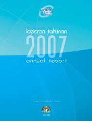
ASM Science Journal, Volume 7(1), 2013performance of the hybrid catalysts for the synthesis ofCNTs were carried out using a fixed-bed chemical vapourdeposition reactor. The physical and chemical propertiesof the hybrid catalysts were then characterized usingX-ray diffraction (XRD), field emission scanning electronmicroscope (FESEM) and thermogravimetric analyser(TGA).MATERIALS AND METHODSPreparation of the CatalystsSeries of hybrid catalysts of Ni:Cu, Ni:Cr and Ni:Mndoped with Pr with the atomic ratio of 3:1:0.3 wereprepared from a mixture of nickel (II) nitrate hexahydrateNi(NO 3 ) 2 .6H 2 O, copper nitrate [Cu(NO 3 ) 2 ], manganese(II) acetate [(CH 3 COO) 2 Mn.4H 2 O], chromium (III)nitrate (Cr(NO 3 ) 3 .6H 2 O) and praseodymium (III) nitrate[Pr(NO 3 ) 3 .6H 2 O], respectively. Optimum quantities of therespected metal salts were dispersed in a sufficient amountof water and mixed well to get a homogeneous mixture ofthe salt solution. The mixture was dried at 80ºC for 24 hand calcined at 700ºC for 5 h. The catalyst mixture wasthen cooled and finely ground into fine powder of hybridcatalyst.Synthesis of Carbon NanotubesThe synthesis was carried out using a horizontal fixedbedCCVD reactor in atmospheric pressure. The reactorconsisted of a tube furnace with a quartz tube where thedecomposition of the acetylene gas took place (Figure1). About of 200 mg of catalyst was placed at the centre(hot zone) of the tube furnace. Nitrogen as the carriergas was simultaneously introduced into the reactor tubeat the flow rate of 0.3 l/min. The mixed gases were thenflown over the catalyst to allow the decomposition of thecarbon precursors to occur. The reaction was left for 30min at 700ºC. The reaction chamber was then cooled toroom temperature. The yield in the form of black powderwas collected and the percent of carbon composition wasdetermined from Equation 1:Carbon yield (%) = M 1M 2Where, M 1 is the mass of carbon deposited after the reactionand M 2 is the mass of catalyst used.The Hybrid CatalystsCHARACTERIZATIONThe identification of metallic bulk crystallographic andamorphous phase in the hybrid catalysts were carried(1)out by XRD. The analysis of the hybrid catalyst by XRDwere conducted using Diffractometer D500 SiemensCrystalloflex with CuKα (λ = 1.54060 Ǻ) as the radiationsource.The As-synthesized CNTsThe as-synthesized CNTs were characterized by theJSM-6701F field emission scanning electron microscope(FESEM) to determine the morphology of the CNTs. Thethermal stability and purity of the CNT was analysed usingthe Mettler Toledo TGA.X-ray DiffractionRESULTS AND DISCUSSIONThe type of metal oxide in the hybrid catalysts formulationis one of the factors that influence the catalytic activityand morphology of the deposited carbon (Chai et al.2007; Nyamori et al. 2008). XRD patterns of the hybridcatalysts were shown in Figure 2. From the diffratogrampattern, it shows that the active oxide phase, NiO present inNi:Cr/Nd and Ni:Mn/Nd catalysts. While in Ni:Cu/Ndcatalysts, Ni species tends to form the binary oxides ofNi 19 CuO 20 with high peaks intensity. It was identified inthis work that the presence of NiO phase had contributedto the high production of CNTs with the mass of yield 18times greater than the initial mass of the Ni:Cr/Nd andNi:Mn/Nd catalysts used respectively, but not for Ni:Cu/Nd catalyst.In comparison to the respective diffractograms pattern ofthe hybrid catalysts, it was observed that Ni:Cr/Nd was inthe amorphous form, while the hybrid Ni:Mn/Nd and Ni:Cu/Nd catalysts represented the polycrystallite form. This newformulated hybrid catalysts of the respected Ni:Mn/Nd andNi:Cu/Nd had generated two types of crystallite structures.Firstly, the spinal oxide of NiMn 2 O 4 which was observedin the hybrid Ni:Mn/Nd catalyst formulation, constructedfrom NiO and Mn 2 O 3 phases and served as the active sitefor the excellent catalytic performance in the production ofCNTs. Secondly, the ternary oxide of Nd 4 (CuNi)O 8 whichwas present in the Ni:Cu/Nd catalyst and constructed frommetal ions of various oxidation states of Ni 2+ , Cu 2+ andNd 3+ in the perovskite type of oxide. The ternary oxidein the hybrid catalyst of Ni:Cu/Nd existed as Ni 19 CuO 20phase, instead of Ni 20 O 20 (or NiO phase). The molecularformula of the perovskite oxide showed that one mole ofthe Ni site in the NiO lattice cluster was probably replacedby one mole of Cu 2+ ion, and resulted in the reduction of thecatalytic performance of the NiO phase in the formulatedNi:Cu/Nd hybrid catalyst.From the catalytic measurement of the Ni based hybridcatalysts, results obtained revealed that the incorporation2
B. Nor Aziah and I. Fatiha: New Formulated Hybrid Catalysts for the Synthesis of Carbon NanotubesMicro-reactorN 2 flowmeterTube furnaceN 2regulatorAcetyleneregulatorMixing chamberAcetyleneflow meterCatalystNitrogengasAcetylene gasFume hoodGas trapFigure 1. Diagram of the fixed-bed CCVD reactor.Crof the Cr, Mn and Cu, in the hybrid catalyst formulations 2 O 3NdCr(O(Philippe 2009), and as 3 )NiOfor the larger diameter CNTs theaffected 29the catalytic performance of the respected catalyst. applications was more to the fabrication of advanced28It also proved that Ni was acting as the active species while composite materials.27Cr was acting 26 as the dispersant to hinder the aggregation of The Ni:Mn/Nd catalyst gave the highest density of25Ni particle, so as to control the particle size of the catalyst, CNTs, whereas the Ni:Cr/Nd catalyst exhibited (a) better24and it was23in agreement with the work done by Chen and quality CNTs. The Ni:Mn/Nd and Ni:Cu/Nd hybridWu (2005). 22 The agglomeration and aggregation process catalysts gave non-uniform CNTs with the mixture of21among the Ni particles were further hindered by the addition different forms of carbon nanomaterials (Figure 3b and 3c).20Nd 2 O 2 (O 2 )NiMn 2 O 4NiOof small 19amounts of Nd as the dopant, hence, it stabilized The small diameter CNTs was observed when using Ni:Cr/18the size of the particles of catalyst in the nanometer range. Nd (Figure 3a) due to the presence of small sized particles17In addition, 16 with the assistance of the respected Mn and Cr of catalyst which were assigned earlier as amorphous in thein the Ni 15 based hybrid catalysts formulation, the reduced XRD analysis.14(b)environment during the synthesis was sustained. Thus,13it contributed 12 towards the controlled production of the The presence of spinal NiMn 2 O 4 compound in the11specific form of CNTs.Ni:Mn/Nd hybrid catalyst formulation gave the highest10CuO Nddensity of 4 (CuNi)Oproduction 8 Niof as-synthesized 19 CuO 209CNTs. The8common active species, NiO had catalyzed the growth of76CHARACTERIZATION OF THE AS-CNTs in Ni:Mn/Nd and Ni:Cr/Nd hybrid catalysts. TheSYNTHESIZED 5CARBON NANOTUBES combination of Ni:Cu/Nd hybrid catalyst resulted in the4formation of ternary oxide of Nd 4 (CuNi)O(c)8 . This ternary3Micrograph 2 of FESEMcompound had initiated the formation of the mixture of1carbon nanomaterials with the large diameter of 50 nm0FESEM micrographs in Figure 3 confirmed the morphology (Figure 3c). The presence of the specific oxide phases in20 30 40 5060 70 80 90of all carbon nanomaterials obtained by the decomposition the hybrid catalysts identified from the XRD analysis had2-Theta - Scaleof acetylene at 700ºC over Ni:Cr/Nd, Ni:Mn/Nd and clearly explained its contribution towards the morphologyNi:Cu/Nd hybrid catalysts are the CNTs. This proved that of the as-synthesized CNTs observed from the FESEM.each of the hybrid catalysts were able to produce CNTsbut they differed in term of the quality. The diameter of From the micrographs of the FESEM, it was noted thatCNTs obtained was within the range of 10 nm to 50 nm. the growth mechanism of MWCNT followed the basedThe smaller diameter CNTs plays an important role, growth model, indicated by the absence of white spots atspecifically in the gas storage application and bio-sensors the tips of the CNTs floss (Anne-Claire 2005).Lin (Cps)3
- Page 1 and 2: ContentsASM Sc. J.Volume 7(1), 2013
- Page 3 and 4: INTERNATIONAL ADVISORY BOARDAhmed Z
- Page 5: The Academy of SciencesMalaysia (AS
- Page 8 and 9: NEWS FOCUSBio-Jet Fuel — Challeng
- Page 12 and 13: NitrogengasAcetylene gasFume hoodGa
- Page 14 and 15: ASM Science Journal, Volume 7(1), 2
- Page 16 and 17: ASM Science Journal, Volume 7(1), 2
- Page 18 and 19: ControllerN 2N 2ValveValvePreheater
- Page 20 and 21: ASM Science Journal, Volume 7(1), 2
- Page 22 and 23: ASM Science Journal, Volume 7(1), 2
- Page 24 and 25: ASM Science Journal, Volume 7(1), 2
- Page 26 and 27: ASM Sci. J., 7(1), 18-22Electron-ph
- Page 28 and 29: v I= v MthASM Science Journal, Volu
- Page 30 and 31: ASM Science Journal, Volume 7(1), 2
- Page 32 and 33: ASM Science Journal, Volume 7(1), 2
- Page 34 and 35: ASM Science Journal, Volume 7(1), 2
- Page 36 and 37: ASM Science Journal, Volume 7(1), 2
- Page 38 and 39: ASM Science Journal, Volume 7(1), 2
- Page 40 and 41: 4.2 × 10 -5Magnetic energy (Em) Ma
- Page 42 and 43: 2.0 × 10 -5Inductance (L)Magnetic
- Page 44 and 45: ASM Science Journal, Volume 7(1), 2
- Page 46 and 47: addition, examination of the freque
- Page 48 and 49: equipped with a computer image anal
- Page 50 and 51: Storage modulus (Pa)1.80E+101.60E+1
- Page 52 and 53: (a)(b)(c)Figure 6. Micrographs: (a)
- Page 54 and 55: 0 20 40 60 80 100 120 140 160 180 2
- Page 56 and 57: 0.00 20 40 60 80 100 120 140 160180
- Page 58 and 59: 0 20 40 60 80 100 120 140 160Temper
- Page 60 and 61:
2.0100.00 20 40 60 80 100 120 140 1
- Page 62 and 63:
3.02.53.02.02.5CB10TSSAlbipoxTimber
- Page 64 and 65:
Figure 18. SEM micrographs of the f
- Page 66 and 67:
Crawford, E & Lesser, AJ 1998, ‘T
- Page 68 and 69:
ASM Science Journal, Volume 7(1), 2
- Page 70 and 71:
ASM Science Journal, Volume 7(1), 2
- Page 72 and 73:
ASM Science Journal, Volume 7(1), 2
- Page 74 and 75:
ASM Science Journal, Volume 7(1), 2
- Page 76 and 77:
ASM Science Journal, Volume 7(1), 2
- Page 78 and 79:
ASM Science Journal, Volume 7(1), 2
- Page 80 and 81:
ASM Science Journal, Volume 7(1), 2
- Page 82 and 83:
Climate Change — Environment andI
- Page 84 and 85:
ASM Science Journal, Volume 7(1), 2
- Page 86 and 87:
ASM Science Journal, Volume 7(1), 2
- Page 88 and 89:
ASM Science Journal, Volume 7(1), 2
- Page 90 and 91:
Announcements!!!!!!!!!!!!!!!!!!!!!!
- Page 93 and 94:
ASM PublicationsMosquitoes and Mosq
- Page 95 and 96:
ASM PublicationsEnhancing Animal Pr
- Page 97 and 98:
ASM PublicationsThe Red Jungle Fowl
- Page 99 and 100:
Vol. 3, No. 1, June : 1823-6782ASM
- Page 101 and 102:
ASM PublicationsIn Pursuit of Excel
- Page 103 and 104:
ASM PublicationsASM Lecture SeriesW
- Page 105 and 106:
ASM PublicationsA Nobel Trip to Lin
- Page 107 and 108:
Vol. 6, No. 2, December 2012 • IS
- Page 109 and 110:
About the JournalMission StatementT
- Page 111:
ASM SCIENCE JOURNAL(ASM Sc. J.)ORDE
- Page 114:
NEWS FOCUSBio-Jet Fuel — Challeng