EN / ACS800-31/U31 Hardware Manual - Simark Controls
EN / ACS800-31/U31 Hardware Manual - Simark Controls
EN / ACS800-31/U31 Hardware Manual - Simark Controls

Create successful ePaper yourself
Turn your PDF publications into a flip-book with our unique Google optimized e-Paper software.
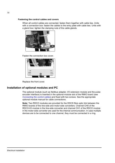
70Fastening the control cables and coversWhen all control cables are connected, fasten them together with cable ties. Unitswith a connection box: fasten the cables to the entry plate with cable ties. Units witha gland box: tighten the clamping nuts of the cable glands.Fasten the connection box cover.Replace the front cover.Installation of optional modules and PCThe optional module (such as fieldbus adapter, I/O extension module and the pulseencoder interface) is inserted in the optional module slot of the RMIO board (seeConnecting the control cables) and fixed with two screws. See the appropriateoptional module manual for cable connections.Note: Two RDCO modules are provided for the DDCS fibre optic link between theRMIO boards of the line-side and motor-side converters. Channel CH0 of theRDCO-03 module in the line-side converter and channel CH1 of the RDCO modulein the motor-side converter are used for the internal communication. In case multipledevices are to be connected to one channel, they must be connected in a ring.Electrical installation