EIA/IPC/JEDEC J-STD-075 Classification of Non-IC Electronic - SMTA
EIA/IPC/JEDEC J-STD-075 Classification of Non-IC Electronic - SMTA
EIA/IPC/JEDEC J-STD-075 Classification of Non-IC Electronic - SMTA
- No tags were found...

You also want an ePaper? Increase the reach of your titles
YUMPU automatically turns print PDFs into web optimized ePapers that Google loves.
<strong>EIA</strong>/<strong>IPC</strong>/<strong>JEDEC</strong> J-<strong>STD</strong>-<strong>075</strong><strong>Classification</strong> <strong>of</strong> <strong>Non</strong>-<strong>IC</strong> <strong>Electronic</strong>Components for Assembly Processes(Post March 2008 Ballot with EditorialCorrections for Publication - April 2008)<strong>Electronic</strong> Components, Assemblies & Materials Association2500 Wilson BlvdArlington, VA 22201-3834Phone: (703) 907-8022Fax: (703) 875-8908<strong>IPC</strong> – Association Connecting <strong>Electronic</strong>s Industries®3000 Lakeside Drive, Suite 309SBannockburn, IL 60015-1249Phone: (847) 615-7100Fax: (847) 615-7105<strong>JEDEC</strong> Solid State Technology Association2500 Wilson Blvd.Arlington, VA 22201-3834Phone: (703) 907-7559Fax: (703) 875-8908
UPDATED DRAFT DOCUMENT POST APRIL 2008 BALLOTING WITH EDITORIAL CORRECTIONS (READYFOR PUBL<strong>IC</strong>ATION) 4-11-08Table <strong>of</strong> Contents1 Scope 32 Purpose 33 Definitions 34 Agreements 35 Applicable Documents 36 Solderability 37 Process 37.1 Process Sensitive Components 47.2 PSL Reclassification 47.3 PSL Evaluation 47.4 MSL Bake Out Conditions 48 PSL <strong>Classification</strong> 69 Number <strong>of</strong> Passes/Reflows 710 Rework 711 Fluxes 712 Cleaning 713 Base Wave Solder Process Conditions 814 Base Reflow Process Conditions 1015 MSL <strong>Classification</strong> and Labeling/Packing 1116 PSL Labeling 11Standard Improvement Formend2
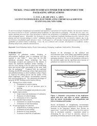
UPDATED DRAFT DOCUMENT POST APRIL 2008 BALLOTING WITH EDITORIAL CORRECTIONS (READYFOR PUBL<strong>IC</strong>ATION) 4-11-081 Scope This standard outlines worst case industry solder assembly process conditions (Sn Pb and Pb free) for nonsemiconductorelectronic components (hereafter referred to as “components”) along with commodity specific exceptions tothe worst case solder assembly process conditions. The solder assembly process conditions listed in this document representcommon industry limits <strong>of</strong> a given component or component family and are not recommended conditions for an assembler.An individual Supplier’s component capability may be better or worse than values documented in this specification. Anassembler needs to take into account many factors when establishing a safe assembly process for a given electronic assembly(card). This standard outlines a process to classify and label non-semiconductor electronic component’s Process SensitivityLevel (PSL) and Moisture Sensitivity Level (MSL) consistent with the semiconductor industry’s classification levels (J-<strong>STD</strong>-020 Moisture/Reflow Sensitivity <strong>Classification</strong> for <strong>Non</strong>hermetic Solid State Devices and J-<strong>STD</strong>-033 Handling, Packing,Shipping and Use <strong>of</strong> Moisture/Reflow Sensitive Surface Mount Devices). This specification does not establish re-workconditions.2 Purpose The purpose <strong>of</strong> this specification is to establish an agreed set <strong>of</strong> worst case solder process conditions (Sn Pb andPb free) which can safely be used for non-semiconductor electronic components on FR4 type or ceramic laminates, alongwith documenting unique commodity specific exceptions. The documented process conditions are used to evaluate a nonsemiconductorcomponent’s PSL and MSL. It is important for Component Manufacturers (hereafter referred to as“Suppliers”), Users and Card Assemblers to be highly familiar with this standard’s information and processes to insureoptimal product quality and reliability.3 DefinitionsFamilyMSLPSLPTHSMTSupplierA grouping <strong>of</strong> components by similar/common characteristics (e.g. package; design; materials; technology andor manufacturing process).Moisture Sensitivity Level – A rating indicating a components susceptibility to damage due to absorbedmoisture when subjected to reflow soldering (see J-<strong>STD</strong>-020).Process Sensitivity Level – A rating used to identify a component that is process solder process sensitivebecause the component can not be used in one or more <strong>of</strong> the base solder process conditions.Pin Through HoleSurface Mount TechnologyThe component manufacturer or seller that controls the component specifications and is accountable for thecomponent’s performance.4 Agreements When referenced by a Supplier, User or Assembler, this standard becomes part <strong>of</strong> theirrequirements/specifications.5 Applicable Documents The following documents, in their current revision, form a part <strong>of</strong> this specification to the extentspecified herein.<strong>IPC</strong>-CH-65 Guidelines for Cleaning Printed Circuit Boards and AssembliesJ-<strong>STD</strong>-002 Solderability Tests for Component Leads, Terminations, Lugs, Terminals and WiresJ-<strong>STD</strong>-004 Requirements for Soldering FluxesJ-<strong>STD</strong>-020 Moisture/Reflow Sensitivity <strong>Classification</strong> for <strong>Non</strong>hermetic Solid State DevicesJ-<strong>STD</strong>-033 Handling, Packing, Shipping and Use <strong>of</strong> Moisture/Reflow Sensitive Surface Mount Devices6 Solderability: Component solderability shall be evaluated and classified according to J-<strong>STD</strong>-002.7 Process: The process for using this specification is outlined in Figure 7-1.The process begins with Supplier’s evaluating all component families against each “base” solder process conditions definedin this document and classifying the PSL. Components which cannot meet these “base” conditions are defined as being3
UPDATED DRAFT DOCUMENT POST APRIL 2008 BALLOTING WITH EDITORIAL CORRECTIONS (READYFOR PUBL<strong>IC</strong>ATION) 4-11-08process sensitive. If the component can meet a defined solder process condition, its MSL shall be evaluated using that solderprocess condition and J-<strong>STD</strong>-020. This MSL evaluation applies to all SMT components and PTH components evaluated forSMT (e.g. paste in hole) assembly. Components shipped from Suppliers shall be labeled and packed per J-<strong>STD</strong>-033 for MSLand this document for PSL (see clause 16).7.1 Process Sensitive <strong>Classification</strong>: When a Supplier has determined that a component is process sensitive (e.g. the 2 nd PSLcharacter is >0) because the component cannot be used in one or more <strong>of</strong> the base solder process conditions, the Suppliershall review the Base Solder Process Exception Listings (see clauses 13 and 14) to determine if there are documentedexception process conditions listed for that component (family). If component (family) exception conditions are noted in thetable, those conditions shall be used to evaluate the component’s PSL compliance. If the Supplier’s component (family)meets the PSL as listed in the Base Solder Process Exception Listings, MSL shall be evaluated at those process conditions.Where a Supplier’s component cannot be used in one or more <strong>of</strong> the base processes and or that Supplier’s component(family) does not comply with the classification as listed in the Base Solder Process Exception Listings, the Supplier shall:a. Determine the process conditions (PSL and MSL) for which this component (family) may be used using the parametersreferenced in this standard as a common means <strong>of</strong> communication within the industry.b. Document to Users and Assemblers acceptable process conditions until item c below has been completed.c. Work with other Suppliers through that components standards development agency to have this standard updated toinclude that component (family) in the Base Solder Process Exception Listings (see clauses 13 and 14). A StandardImprovement form is included in the back <strong>of</strong> this document to submit recommendations.d. Use the process conditions in item b (until item c is published) to evaluate the components performance at that processcondition and subsequent Moisture Sensitivity analysis, classification and packaging labeling, as outlined above.If a Supplier’s component is included in a Base Solder Process Exception Listings but that Supplier’s component capability isless than noted in the tables 13-1 and 14-1, the Supplier shall use the classification they determined to be appropriate anddocument the acceptable process conditions, as per item b above.7.2 PSL Reclassification: The component (family) ability to meet these process conditions shall be re-evaluated by theSupplier for any process change affecting material or component manufacturing process/controls.7.3 PSL Evaluation: The solder process evaluation includes the number <strong>of</strong> reflows, flux application, thermal pr<strong>of</strong>ile andsubsequent wash processes outlined in this document.The values in the Base Solder Process Exception Listings define the changes to the base solder process in order to safely usethe listed family <strong>of</strong> components (see clauses 13 and 14). Where a dash “-“ is specified in the table there are no changes to thatparameter <strong>of</strong> the base solder process.7.4 MSL Bake Out: Unless otherwise noted, the bake out conditions outlined in J-<strong>STD</strong>-020 for moisture sensitivecomponents shall apply. Suppliers should be contacted for support <strong>of</strong> other bake out conditions.4
UPDATED DRAFT DOCUMENT POST APRIL 2008 BALLOTING WITH EDITORIAL CORRECTIONS (READYFOR PUBL<strong>IC</strong>ATION) 4-11-08AStartYesClassify PSL(Can meet basesolder pr<strong>of</strong>ile?)NoReview J-<strong>STD</strong>-<strong>075</strong>Commodity solder pr<strong>of</strong>ileException listingYesCancomponent meetcommodity specificException listingsolder pr<strong>of</strong>ile?NoEvaluate component forMoisture Sensitivity perJ-<strong>STD</strong>-020 with base solderpr<strong>of</strong>ile or commodity specificpr<strong>of</strong>ile, as applicable.- Evaluate and determine the componentssolder process compatibility- Document solder process limits to Users- Request update/addition to commodityexception listing *Is componentMoisture Sensitive?NoUse PSL and MSLInformationNoYesComponent,J-<strong>STD</strong>-<strong>075</strong> or J-<strong>STD</strong>-020changes?- Document Moisture Sensitivity to Users- Label PSL per J-<strong>STD</strong>-<strong>075</strong> and label MSL andpack per J-<strong>STD</strong>-033YesA* Commodity exception listing shall be updated via requests processed by the commodity’s specificengineering standards committee.Figure 7-1 J-<strong>STD</strong>-<strong>075</strong> Process5
UPDATED DRAFT DOCUMENT POST APRIL 2008 BALLOTING WITH EDITORIAL CORRECTIONS (READYFOR PUBL<strong>IC</strong>ATION) 4-11-088. PSL <strong>Classification</strong> Supplier’s shall evaluate and classify their component’s PSL to the worst case process conditions asoutlined in this specification for that commodity, per the classification scheme listed in this clause.Tables 8-1 and 8-2 provide the wave solder and reflow solder PSL classification scheme. PSL classifications will alwayshave at least two characters and there may be an optional 3rd character. The first character defines the process being limited,with “W” used for wave soldering or “R” used for reflow soldering. These designations are intended to minimize confusionwith J-<strong>STD</strong>-020 moisture sensitivity levels. If a component meet or exceeds the base solder process conditions, PSL values <strong>of</strong>W0” and or “R0” shall be used.The 2nd character identifies the classification temperature (T c ). PSL designators R1 to R3 are not used in Table 8-2 at thistime so that the temperature classifications for W4 through W8 will be the same as R4 through R8. For example, the W5wave temperature and R5 classification temperature are both 255 °C.The 3rd character is optional and identifies other process limitations, as defined in Table 8-3. Exception Table 13-1 providesexamples <strong>of</strong> wave solder PSL classifications and exception Table 14-1 provides examples <strong>of</strong> reflow solder PSLclassifications. Suppliers should be contacted for PSL and MSL classification information <strong>of</strong> their components.PSL<strong>Classification</strong>Table 8-1 Wave Solder PSL <strong>Classification</strong>Is the component process sensitive? <strong>Classification</strong> Temp (T c )W0 No -W1 Yes 1 275 °C or greaterW2 Yes 1 270 °CW3 Yes 1 265 °CW4 Yes 1 260 °CW5 Yes 1 255 °CW6 Yes 1 250 °CW7 Yes 1 245 °CW8 Yes 1 240 °CW9 Yes 1,2 -Note 1: See Table 8-3 if a 3 rd PSL character is specified.Note 2: The component has been determined to be process sensitive but this standard does not specify the processsensitivity exceptions. The Supplier must be contacted for recommended solder process conditions.Table 8-2 Reflow Solder PSL <strong>Classification</strong>PSL <strong>Classification</strong> Is the component process sensitive? <strong>Classification</strong> Temp (T c )R0 No -R1 Yes 1 N/AR2 Yes 1 N/AR3 Yes 1 N/AR4 Yes 1 260 °C or greaterR5 Yes 1 255 °CR6 Yes 1 250 °CR7 Yes 1 245 °CR8 Yes 1 240 °CR9 Yes 1,2 -Note 1: See Table 8-3 if a 3 rd PSL character is specified.Note 2: The component has been determined to be process sensitive but this standard does not specify the processsensitivity exceptions. The Supplier must be contacted for recommended solder process conditions.6
UPDATED DRAFT DOCUMENT POST APRIL 2008 BALLOTING WITH EDITORIAL CORRECTIONS (READYFOR PUBL<strong>IC</strong>ATION) 4-11-08Table 8-3 defines the limitations indicated by the optional PSL 3 rd character.PSL 3 rdCharacterTable 8-3 PSL 3 rd CharacterDefinitionComponent has no additional process limitations beyond the <strong>Classification</strong> Temperatures(Blank)listed in Tables 8-1 or 8-2.A Component has a Thermal Spike limitation.C Component has a Preheat limitation.E Component has a Time in Wave limitation.F Component has a Time (t L ) Above 217 °C liquidous temperature (T L ) limitation.G Component has a Time Within 5 °C <strong>of</strong> T c limitation.H Component has a Ramp Down Rate limitation.J Component has a Number <strong>of</strong> Passes / Reflows limitation.K Component has a Flux limitation.M Component has a Cleaning limitation.N Component has limitations: C; F; G and J.P Component has limitations: C; F; G and H.R Component has limitations C; F and G.YComponent has additional limitations but the combination has not been assigned a code.Details <strong>of</strong> these unique limitations will need to be obtained from the Supplier.The Supplier must be contacted for the details regarding the PSL 3 rd character specified limitations. The worst case processsensitivity should be recorded in all cases. If a component has both wave solder and reflow process limitations, bothclassifications should be established.9 Number <strong>of</strong> Passes/Reflows All components supporting wave solder shall be capable <strong>of</strong> 2 passes, unless noted in the BaseSolder Process Exception Listings. All components supporting reflow processes shall be capable <strong>of</strong> 3 reflows unless noted inthe Base Solder Process Exception Listings.10 Rework This document does not address the unique processes used in rework and Suppliers should be contacted forspecific rework limitations that may be associated with a component. It is necessary to pay close attention to the processeffects imposed on adjacent components and ensure that rework conditions do not exceed any <strong>of</strong> the adjacent componentprocess limitations.11 Flux Components shall be capable <strong>of</strong> withstanding the following fluxes and the flux materials outlined in J-<strong>STD</strong>-004:• Mildly to highly activated water soluble fluxes• No-clean fluxes• Corrosive Flux (ph 1-2) only for PTH components and all SMT components where the Supplier has identified wavesolder as an acceptable process for their component (family).12 Cleaning Components shall be capable <strong>of</strong> withstanding typical cleaning processes outlined in <strong>IPC</strong>-CH-65. Componentfamilies unable to withstand one or more <strong>of</strong> the cleaning processes shall be noted in the Base Process Exception tables.7
UPDATED DRAFT DOCUMENT POST APRIL 2008 BALLOTING WITH EDITORIAL CORRECTIONS (READYFOR PUBL<strong>IC</strong>ATION) 4-11-0813 Base Wave Solder Process Conditions This process shall apply to all PTH components (non-wave side placement) andall SMT components (full wave submersion), where the Supplier has identified wave solder as an acceptable process for theircomponent (family). This process includes lead free solder soldering. For SMT components (full wave submersion), alltemperatures are measured on the component body. For PTH components (non-wave side placement), all temperatures aremeasured on the component lead. The base wave solder process conditions are as follows, except where noted in the Table13-1:Thermal Spike: The thermal spike from preheat to the wave solder shall be no more than 160 °C.Wave Solder Temperature (max.): 275°CTotal Time in Wave (max): 10 secondsRamp-down Rate (average rate °C/s.): Not specified (see table 13-1)CommodityCeramic ChipCapacitors<strong>Non</strong>-Fused (MnO2)TantalumCapacitors < 2.5mmin height<strong>Non</strong>-Fused (MnO2)TantalumCapacitors >=2.5mm in height<strong>Non</strong>-Fused(Polymer) TantalumCapacitorsPTH ConnectorsTable 13-1 Base Wave Solder Process Exceptions(A Supplier’s component capability may be greater than noted in the table)ThermalSpike<strong>Classification</strong>Temperature(T c)Time inWaveRamp-DownRate(Note 1)Number <strong>of</strong>Passes- - - - - - -Fluxes Cleaning PSL/NotesSee Table13-2- 265 °C - - - - - W3A- 265 °C - - - - -W3ANote 2Note 3 Note 3 - - - - - Note 3See Supplier specific component wave solder information and recommendations. PSLclassification to this specification is required.( – ) = No Exception SpecifiedNote 1: Ramp Down Rate is the average cooling rate in °C/s.Note 2: Tantalum capacitors <strong>of</strong> this package size can have “solder shadowing” assembly issues, due to the component height.Note 3: Only a minority <strong>of</strong> SMT polymer tantalum Suppliers support wave soldering (full wave submersion). Users andAssemblers should contact the Supplier to verify wave solder support and allowable solder conditions for these SMTcomponents.8
UPDATED DRAFT DOCUMENT POST APRIL 2008 BALLOTING WITH EDITORIAL CORRECTIONS (READYFOR PUBL<strong>IC</strong>ATION) 4-11-08Capacitors specified in Table 13-2 are components recommended for wave solder. A Supplier’s component capability may begreater than noted in the table.Table 13-2CeramicCapacitors forWave SolderingPackageTable 13-2 Ceramic Capacitors for Wave SolderingDielectric Capacitance Range Chip Height (max)0603 C0G All Values
UPDATED DRAFT DOCUMENT POST APRIL 2008 BALLOTING WITH EDITORIAL CORRECTIONS (READYFOR PUBL<strong>IC</strong>ATION) 4-11-0814. Base Reflow Solder Process Condition: This process shall apply to all SMT components and selective PTH components(used in paste in hole applications), where the Supplier has specifically documented support for PTH reflow soldering for aspecific component (family). This process includes lead free soldering. All temperatures are measured on the top center <strong>of</strong> thecomponent body (package body surface facing up during assembly reflow), except for connectors. Due to the large variety <strong>of</strong>unique connector designs and significant process sensitivity variability among connector Suppliers, the connector Supplier’sspecification should be used for temperature measurement location definition. The base reflow solder process conditions aredefined by J-<strong>STD</strong>-020 (where the peak temperature (T c ) is specified as a function <strong>of</strong> the component size), except where notedin Table 14-1.CommodityAluminum Capacitors ≤6.3 mm Dia. and height≤4.5 mmAluminum Capacitors ≤6.3 mm Dia. and height> 4.5 mmAluminum Capacitors >6.3 mm Dia. and ≤10mm Dia.Aluminum Capacitors >10 mm Dia.Plastic Molded PolymerAluminum Capacitorswith heights ≥1.8mmand voltage rating
UPDATED DRAFT DOCUMENT POST APRIL 2008 BALLOTING WITH EDITORIAL CORRECTIONS (READYFOR PUBL<strong>IC</strong>ATION) 4-11-08Time (t L)CommodityCan/coin Type ElectricDouble Layer Carbon –Special CapacitorsCrystals; Oscillators;ResonatorsPreheatTemperature(MaximumTime)TempMax=150C(120 s.)Time (Ts min toTs max )(ts) =120 s. max.Above 217°CLiqudousTemperature(T L )(Note 1)30 s. max.above 200°C<strong>Classification</strong>Temperature(T c )90 s. max. 250 °CFuses (85 s.) 65 s. max. Note 4Inductors andtransformers withinsulated wire typecoilsMin = 100 °CMax = 150 °C(90 s.)60 s. max. Note 4TimeWithin5°C <strong>of</strong>T cRampdownRate(Note 2)Number<strong>of</strong>ReflowsFluxesCleaningPSL/Notes235 °C 5 s. max. - 2 - - R9N10 s.max.20 s.max.20 s.max.5 °C/s. max. - - - R6R5 °C/s. max. - - -5 °C/s. max. - - -<strong>Non</strong>-Solid state Relays Note 5 Note 5 250 °C Note 5 Note 5 Note 5 - -LEDs Note 5 Note 5 Notes 4 and 5 Note 5 Note 5 Note 5 - -SMT Connectors (Pastein Hole)R_PNote 3R_RNote 3R6_Note 3R__Note 3See Supplier specific component reflow information and recommendations. PSL classification to this specification isrequired.( – ) = No Exception SpecifiedNote 1: It may be very difficult to establish a soldering pr<strong>of</strong>ile for a given card for components with t L < 50 s.Note 2: Ramp Down Rate is the average cooling rate in °C/s.Note 3: The underscore “_” denotes that the omitted character shall be defined by the Supplier.Note 4: <strong>Classification</strong> Temp (T c ), the PSL’s 2 nd character, is based upon package thickness (height) and volume per J-<strong>STD</strong>-020 table 4-1. A lower <strong>Classification</strong> Temp (T c ) may be used by Suppliers, if their component can not meet the basesolder process condition.Note 5: There is industry consensus that this component is process sensitive. However, the supported soldering pr<strong>of</strong>ileconditions vary widely by Supplier. The Supplier must be contacted for recommended solder process conditions.15 MSL <strong>Classification</strong> and Labeling/Packing SMT components and selective PTH components (where the pin though holecomponent Supplier has specifically documented support for reflow soldering) shall be evaluated and classified per J-<strong>STD</strong>-020 and label and pack per J-<strong>STD</strong>-033. The process pr<strong>of</strong>ile shall be as outlined in J-<strong>STD</strong>-020, unless the component (family)is listed on the Base Reflow Solder Process Exception List. In that case, the conditions listed in the Exceptions List shall beused for the moisture sensitivity evaluation. Components (families) shall not be classified, with regard to moisture sensitivity,at process conditions exceeding the PSL classification conditions.Care should be taken to insure that any noted failures are attributed to moisture effects and not other process effects. If a failmechanism can not be attributed to moisture, the component‘s (family’s) ability to meet the defined solder process should beinvestigated. Each fail shall be attributed to either inability to meet the solder process (for example: “thermal”) or inability towithstand moisture absorption or both (where a fail can not be clearly separated into discrete causes).16 PSL Labeling Component Manufacturers shall publish their component’s PSL classification and label (machine printed)their first level containers (tape and reel, bag or box) with the PSL classification when the 2 nd character <strong>of</strong> the PSL is >0. Therecommended labeling is:Wave Solder: “WARNING: PSL = W__”, where ’__’ is the 2 nd and 3 rd (optional) PSL classification level characters.Reflow: “WARNING: PSL = R__”, where ’__’ is the 2 nd and 3 rd (optional) PSL classification level characters.If a component is both wave solder and reflow process sensitive, both classifications shall be labeled, as outlined above.11
UPDATED DRAFT DOCUMENT POST APRIL 2008 BALLOTING WITH EDITORIAL CORRECTIONS (READYFOR PUBL<strong>IC</strong>ATION) 4-11-08The Standard Improvement Form will be added at time <strong>of</strong> publication. It will follow the format <strong>of</strong> the StandardImprovement Forms that are in the back <strong>of</strong> other Joint Standards such as J-<strong>STD</strong>-020.12