Alex Popescu ESA/ESTEC Satellite Design and Status
Alex Popescu ESA/ESTEC Satellite Design and Status
Alex Popescu ESA/ESTEC Satellite Design and Status

Create successful ePaper yourself
Turn your PDF publications into a flip-book with our unique Google optimized e-Paper software.
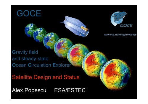
GOCE<br />
Gravity field<br />
<strong>and</strong> steady-state<br />
Ocean Circulation Explorer<br />
<strong>Satellite</strong> <strong>Design</strong> <strong>and</strong> <strong>Status</strong><br />
<strong>Alex</strong> <strong>Popescu</strong> <strong>ESA</strong>/<strong>ESTEC</strong><br />
EOEP Science Review Meeting 14 <strong>and</strong> 15 June 2005<br />
www.esa.int/livingplanet/goce
GOCE Mission Objectives<br />
- Determine the Earth’s gravity field with an accuracy of 1 mgal<br />
(I.e. 1 millionth of the Earth Gravity) via the measurement of<br />
the diagonal components of the gravity gradient tensor<br />
- Determine the geoid (I.e. the equipotential surface for a<br />
hypothetical ocean at rest ) with a radial accuracy of 1 to2 cm<br />
- Achieve this at length scales down to 100 km
GOCE: Main Payload Characteristics<br />
- The Gradiometer (EGG): Measuring the diagonal components of<br />
the gravity gradient tensor with an accuracy of 6 mE/sqrt(Hz)<br />
within a b<strong>and</strong>width of 5 mHz to 100 mHz, i.e. consistent with<br />
degree <strong>and</strong> order 10 to 200<br />
- The High-to-Low <strong>Satellite</strong> to <strong>Satellite</strong> Tracking Receiver (SSTI):<br />
Orbit reconstitution with an accuracy of 1-2 cm
• Electrostatic Gravity<br />
Gradiometer<br />
• 6 tri-axial electrostatic<br />
accelerometers for the<br />
measurement of the<br />
gravity gradient tensor<br />
• <strong>Satellite</strong>-to-<strong>Satellite</strong>-<br />
Tracking Instrument<br />
(SSTI)<br />
• 3 Star trackers<br />
• GPS antenna & 12channel<br />
L1/L2 receiver<br />
for precise orbit<br />
determination<br />
• Laser Retroreflector<br />
GOCE payload <strong>and</strong> satellite
GOCE <strong>Satellite</strong>: Main Requirements<br />
Orbit: Circular <strong>and</strong> as low as possible but still compatible<br />
with capability to:<br />
• compensate the drag<br />
• not loose the satellite in case of an on-board anomaly<br />
Injection altitude = 275 km, geodetic measurement altitude =<br />
250/260 km<br />
Other orbit characteristics: * 96.5deg inclination for near global<br />
coverage<br />
* Dawn-dusk sun-synchronous orbit to allow for maximum solar<br />
power<br />
Total measurement time:<br />
2 times 6 months with additional 6 months possible extension<br />
<strong>Design</strong> requirement: No moving parts <strong>and</strong> ultra-high thermo-elastic
GOCE <strong>Satellite</strong>: Main <strong>Design</strong> Divers<br />
• Spacecraft Cross Section minimized in the flight direction<br />
• Accommodation of Gradiometer Instrument (close to C.o.M)<br />
• High thermo-elastic stability<br />
• Provisions to minimize Micro-disturbance Effects<br />
• High level of Autonomy (up to 72 hours)<br />
• Autonomous Survival Capability up to 8 days
0.2 gram<br />
… feeling for the numbers<br />
1 000 000 tonne<br />
Downforce<br />
~2E-03 N<br />
Super-tanker acceleration:<br />
! 3<br />
2" 10 N<br />
! 12<br />
# 2"<br />
10<br />
9<br />
1"<br />
10<br />
kg<br />
m<br />
2<br />
s
GOCE Spacecraft
X GR<br />
Z GR<br />
A 1<br />
Y GR<br />
A 3<br />
A 5<br />
A 2<br />
X O<br />
A 4<br />
A 6<br />
Z O<br />
Y O<br />
O O<br />
Gradiometer configuration <strong>and</strong> data processing<br />
u<br />
Z J2000<br />
X J2000<br />
Reconstruction of the Gravity Gradient<br />
Tensor components (Level 1b product):<br />
aˆ d<br />
,14, X 2 2,…….<br />
Û XX = " 2 " ! ˆ Y " ! ˆ Z<br />
Lˆ<br />
X<br />
!<br />
i<br />
Linear accelerations measured by the six<br />
accelerometers of the Electrostatic Gravity<br />
Gradiometer: a' 1,X , a' 1,Y , a' 1,Z , ……., a' 6,X , a' 6,Y , a' 6,Z<br />
Y J2000<br />
Application of Gradiometer Calibration<br />
Matrices: M 14 , M 25 , M 36 , containing the<br />
accelerometer scale factors, sensitive axes<br />
alignments (during on-orbit calibration only)<br />
Measured accelerations corrected by means of the<br />
Calibration Matrices ! actual accelerations experienced<br />
by the proof masses: a 1,X , a 1,Y , a 1,Z , ……., a 6,X , a 6,Y , a 6,Z<br />
Reconstruction of centrifugal accelerations measured by<br />
the Gradiometer & star tracker along 3 axes: " X 2 , "Y 2 , "<br />
Z 2
Electrostatic Gravity Gradiometer<br />
The 6 accelerometers are situated around the<br />
center of mass of the satellite
3 pairs of GOCE Accelerometers<br />
q Pt-Rh proof mass of 4x4x1 cm <strong>and</strong> 320 g<br />
mass<br />
q Accelerometer cage made of ULE ceramics<br />
with gold electrodes for 6 DOF control<br />
q Sole plate in INVAR<br />
q 8 electrode pairs per sensitive element (for<br />
redundancy reasons)<br />
q Proof mass grounded by a 25 mm long <strong>and</strong><br />
5 micron “thick” gold wire
Accelerometer Sensor Head: Assembled
ASH FM 1
Carbon-Carbon Arm Structure<br />
with Accelerometer Pair, including<br />
magnetic shielding <strong>and</strong> connectors<br />
One-Axis Gradiometer<br />
OAGY: Y-direction
Gradiometer Structural Model
Gradiometer Electrical Sub-System FM
SSTI configuration <strong>and</strong> data processing<br />
Science Data Processing<br />
L1, L2 carrier phases <strong>and</strong><br />
pseudo-range (code) measured<br />
by the GPS receiver for up to<br />
12 GPS satellites, <strong>and</strong> receiver<br />
temperatures<br />
Determination of the inter-<br />
frequency bias calibration<br />
parameter from the receiver<br />
temperatures<br />
L1, L2 carrier phase measurements corrected by means of the<br />
estimated inter-frequency bias, satellite positions <strong>and</strong> reconstructed<br />
orbit (Level 1b product)<br />
<strong>Satellite</strong> position determination<br />
from the pseudo-range<br />
measurements <strong>and</strong> orbit<br />
reconstruction<br />
GPS
Laser Retroreflector
Key Performance<br />
Requirements<br />
– Thrust Range 1.5 - 20 mN,<br />
comm<strong>and</strong>ed<br />
@ 10 Hz<br />
– Thrust Error: # ±8%<br />
– Thrust Vector Stability: < 0.2°<br />
half cone<br />
Ion Propulsion<br />
Implementation Features<br />
– ITA: Qinetiq´s T5 Mk-5<br />
• dished grid system<br />
• hollow cathodes<br />
• magnetic field system<br />
– IPCU:<br />
• 11 ITA power supplies (2<br />
regulated)<br />
• PXFA drive & read-out<br />
interfaces<br />
• processor controlled thrust<br />
regulation,<br />
incl. special FDIR<br />
– PXFA:<br />
• linearly controlled Xe main<br />
flow<br />
• branch isolation by latch<br />
valves
Ion Motor Testing