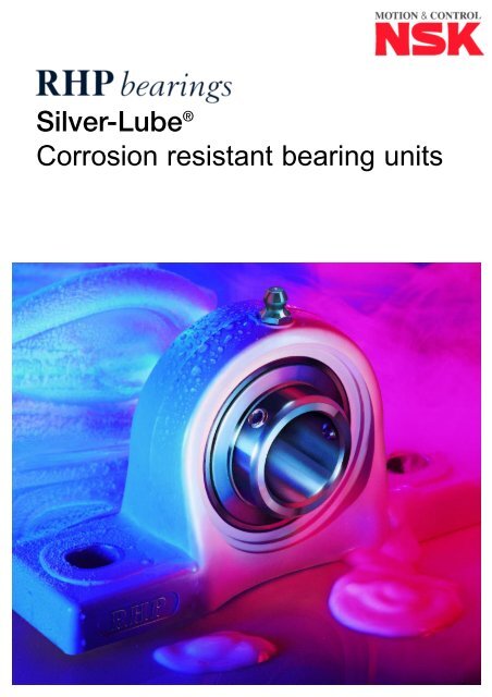
Silver-Lube® Corrosion resistant bearing units
Silver-Lube® Corrosion resistant bearing units
Silver-Lube® Corrosion resistant bearing units
- No tags were found...

Create successful ePaper yourself
Turn your PDF publications into a flip-book with our unique Google optimized e-Paper software.
<strong>Silver</strong>-Lube ®<strong>Corrosion</strong> <strong>resistant</strong> <strong>bearing</strong> <strong>units</strong>
INDEX<strong>Silver</strong>-Lube ®UnitsIntroduction 3Unit Dimensions 5End Covers 7<strong>Silver</strong>-Lube ®HousingsWITHSTANDS FREQUENTWASHDOWNS RESISTING■ <strong>Corrosion</strong>■ Detergents■ Chemicals■ FungicidesMaterial Properties 8Hygiene 8Chemical Resistance 9Water and Steam Resistance 10Ultraviolet Resistance 10Heat Resistance 10Housing Strength 11/12Static Electricity Generation 12<strong>Silver</strong>-Lube ®Bearing InsertsGrease, Temperature Range 14and Component MaterialsDesignations, Dimensions 14and WeightsShaft Tolerances 14and Permissible SpeedsSet Screw Tightening Torques 15Bore Tolerance 152
STAINLESS STEEL■ Grease nipple■ Bolt hole liners■ Set screws■ Flinger■ Seal core■ Bearing rings,cage and ballsRHP SILVER-LUBE ®■ CORROSION RESISTANT UNITS■ STAINLESS STEEL BEARING INSERTS■ EFFECTIVE, EFFICIENT SEALING■ FOOD GRADE GREASE APPROVED TO USDA H1■ WIDE OPERATING TEMPERATURE■ END COVERS AVAILABLEINTRODUCTIONThe RHP <strong>Silver</strong>-Lube ® series is a range of corrosion <strong>resistant</strong><strong>bearing</strong> <strong>units</strong> specifically for use in industries where frequentthorough washdowns are necessary, optimum hygiene standardsare required and good chemical resistance is important over awide temperature range.The <strong>units</strong> are available in pillow block, two-bolt flange, four-bolt flangeand take-up unit configurations and are capable of accommodatinginitial misalignment from mounting errors. In operation the <strong>units</strong>have proven reliability in the most hostile applications.Relubrication is possible for long trouble-free life,minimising maintenance, maximising productivityand helping maintain hygiene standards.<strong>Silver</strong>-Lube ® housings are made from Valox ® 420thermoplastic resin which, in addition to beingnon-corrodable, is <strong>resistant</strong> to detergents and awide range of chemicals. The housings are paint andcoating free which prevents chipping or flaking and have smoothsurfaces to assist thorough washdowns. The housing material alsodemonstrates fungicidal resistance.THERMOPLASTICMOULDED HOUSING■ No coating■ No cracking■ No peeling<strong>Silver</strong>-Lube ® <strong>bearing</strong> inserts are made from stainless steel, areprovided with effective, efficient sealing arrangements and arecharged with an aluminium complex, high temperature USDA H1approved food grade grease, as standard.Full technical specifications, application details and descriptions ofthe <strong>Silver</strong>-Lube ® range are provided within this document.3
4FROM BOTTLING PLANTS TO FISHERIES
A1UNIT DIMENSIONSHN1JLH2G Bolt DiaH1SBNA<strong>Silver</strong>-Lube ® mounting details are dimensionally interchangeable withthe traditional RHP Self-Lube ® range. However, some non-criticaldimensions do differ, see tables below.For permissible <strong>bearing</strong> speeds, please see page 14.PNP SERIESTable 1PNP <strong>Silver</strong>-Lube ® Pillow Blocks – Unit DimensionsRHP SHAFT BASIC HOUSING WEIGHTDESIGNATION DIA. INSERT GROUP L H H1 H2 J N N1 G A A1 B S (kg)PNP20CR 20 J1020 2 127.2 33.3 14.2 65.9 94.9 11.0 14.2 M10 37.8 22.5 31.0 12.7 0.27PNP3/4CR 3/4" J1020 2 127.2 33.3 14.2 65.9 94.9 11.0 14.2 M10 37.8 22.5 31.0 12.7 0.27PNP25CR 25 J1025 3 140.2 36.5 14.5 71.9 104.9 11.0 14.2 M10 37.8 24.5 34.0 14.3 0.39PNP1CR 1" J1025 3 140.2 36.5 14.5 71.9 104.9 11.0 14.2 M10 37.8 24.5 34.0 14.3 0.39PNP30CR 30 J1030 4 162.2 42.9 17.8 83.9 118.9 14.0 18.2 M12 45.8 27.0 38.1 15.9 0.52PNP1.3/16CR 1.3/16" J1030 4 162.2 42.9 17.8 83.9 118.9 14.0 18.2 M12 45.8 27.0 38.1 15.9 0.52PNP1.1/4RCR 1.1/4" J1030 4 162.2 42.9 17.8 83.9 118.9 14.0 18.2 M12 45.8 27.0 38.1 15.9 0.52PNP35CR 35 J1035 5 167.2 47.6 18.0 94.9 126.9 14.0 18.2 M12 47.8 32.5 42.9 17.5 0.72PNP1.1/4CR 1.1/4" J1035 5 167.2 47.6 18.0 94.9 126.9 14.0 18.2 M12 47.8 32.5 42.9 17.5 0.72PNP1.7/16CR 1.7/16" J1035 5 167.2 47.6 18.0 94.9 126.9 14.0 18.2 M12 47.8 32.5 42.9 17.5 0.72PNP40CR 40 J1040 6 184.2 49.2 19.5 98.9 136.8 14.0 18.2 M12 53.8 36.0 49.2 19.0 0.99PNP1.1/2CR 1.1/2" J1040 6 184.2 49.2 19.5 98.9 136.8 14.0 18.2 M12 53.8 36.0 49.2 19.0 0.99All dimensions in mm except inch shaft sizes.LJG BoltDiaPSF SERIESBA1AA4STable 2PSF <strong>Silver</strong>-Lube ® Four-Bolt Flange – Unit DimensionsRHP SHAFT BASIC HOUSING WEIGHTDESIGNATION DIA. INSERT GROUP L J G A A1 A4 B S (kg)PSF20CR 20 J1020 2 86.5 63.5 M10 27.8 36.3 13.4 31.0 12.7 0.28PSF3/4CR 3/4" J1020 2 86.5 63.5 M10 27.8 36.3 13.4 31.0 12.7 0.28PSF25CR 25 J1025 3 95.0 70.0 M10 27.9 36.7 14.3 34.0 14.3 0.34PSF1CR 1" J1025 3 95.0 70.0 M10 27.9 36.7 14.3 34.0 14.3 0.34PSF30CR 30 J1030 4 107.5 83.0 M10 31.5 41.4 14.3 38.1 15.9 0.50PSF1.3/16CR 1.3/16" J1030 4 107.5 83.0 M10 31.5 41.4 14.3 38.1 15.9 0.50PSF1.1/4RCR 1.1/4" J1030 4 107.5 83.0 M10 31.5 41.4 14.3 38.1 15.9 0.50PSF35CR 35 J1035 5 117.5 92.0 M12 34.8 46.9 15.5 42.9 17.5 0.74PSF1.1/4CR 1.1/4" J1035 5 117.5 92.0 M12 34.8 46.9 15.5 42.9 17.5 0.74PSF1.7/16CR 1.7/16" J1035 5 117.5 92.0 M12 34.8 46.9 15.5 42.9 17.5 0.74PSF40CR 40 J1040 6 130.5 102.0 M12 37.5 53.2 17.1 49.2 19.0 0.98PSF1.1/2CR 1.1/2" J1040 6 130.5 102.0 M12 37.5 53.2 17.1 49.2 19.0 0.98All dimensions in mm except inch shaft sizes.5
HLG BoltDiaJPSFT SERIESBA1AA4STable 3 PSFT <strong>Silver</strong>-Lube ® Two-Bolt Flange – Unit DimensionsRHP SHAFT BASIC HOUSING WEIGHTDESIGNATION DIA. INSERT GROUP L H J G A A1 A4 B S (kg)PSFT20CR 20 J1020 2 64.1 113.3 90.0 M10 26.5 33.7 11.4 31.0 12.7 0.24PSFT3/4CR 3/4" J1020 2 64.1 113.3 90.0 M10 26.5 33.7 11.4 31.0 12.7 0.24PSFT25CR 25 J1025 3 68.4 130.3 99.0 M10 29.1 36.7 13.4 34.0 14.3 0.30PSFT1CR 1" J1025 3 68.4 130.3 99.0 M10 29.1 36.7 13.4 34.0 14.3 0.30PSFT30CR 30 J1030 4 80.1 148.3 117.0 M10 30.5 41.2 13.4 38.1 15.9 0.44PSFT1.3/16CR 1.3/16" J1030 4 80.1 148.3 117.0 M10 30.5 41.2 13.4 38.1 15.9 0.44PSFT1.1/4RCR 1.1/4" J1030 4 80.1 148.3 117.0 M10 30.5 41.2 13.4 38.1 15.9 0.44PSFT35CR 35 J1035 5 90.1 163.3 130.0 M12 32.8 43.4 16.1 42.9 17.5 0.64PSFT1.1/4CR 1.1/4" J1035 5 90.1 163.3 130.0 M12 32.8 43.4 16.1 42.9 17.5 0.64PSFT1.7/16CR 1.7/16" J1035 5 90.1 163.3 130.0 M12 32.8 43.4 16.1 42.9 17.5 0.64PSFT40CR 40 J1040 6 100.1 175.3 144.0 M12 37.5 51.7 20.0 49.2 19.0 0.89PSFT1.1/2CR 1.1/2" J1040 6 100.1 175.3 144.0 M12 37.5 51.7 20.0 49.2 19.0 0.89All dimensions in mm except inch shaft sizes.LL1AA1G1HH1BH3SL4PST SERIESG ThreadA2Table 4PST <strong>Silver</strong>-Lube ® Take-Up Units – Unit DimensionsRHP SHAFT BASIC HOUSING WEIGHTDESIGNATION DIA. INSERT GROUP L L1 L4 H H1 H3 G G1 A A1 A2 B S (kg)PST20CR 20 J1020 2 99.0 64.0 47.0 88.0 35.0 75.8 M16x2.00 22.5 27.5 24.5 12.2 31.0 12.7 0.32PST3/4CR 3/4" J1020 2 99.0 64.0 47.0 88.0 35.0 75.8 M16x2.00 22.5 27.5 24.5 12.2 31.0 12.7 0.32PST25CR 25 J1025 3 99.0 64.0 47.0 88.0 35.0 75.8 M16x2.00 22.5 27.5 24.5 12.2 34.0 14.3 0.36PST1CR 1" J1025 3 99.0 64.0 47.0 88.0 35.0 75.8 M16x2.00 22.5 27.5 24.5 12.2 34.0 14.3 0.36PST30CR 30 J1030 4 125.0 76.0 63.0 102.0 40.0 88.8 M16x2.00 22.5 34.5 30.0 12.2 38.1 15.9 0.53PST1.3/16CR 1.3/16" J1030 4 125.0 76.0 63.0 102.0 40.0 88.8 M16x2.00 22.5 34.5 30.0 12.2 38.1 15.9 0.53PST1.1/4RCR 1.1/4" J1030 4 125.0 76.0 63.0 102.0 40.0 88.8 M16x2.00 22.5 34.5 30.0 12.2 38.1 15.9 0.53PST35CR 35 J1035 5 125.0 76.0 63.0 102.0 40.0 88.8 M16x2.00 22.5 34.5 30.0 12.2 42.9 17.5 0.74PST1.1/4CR 1.1/4" J1035 5 125.0 76.0 63.0 102.0 40.0 88.8 M16x2.00 22.5 34.5 30.0 12.2 42.9 17.5 0.74PST1.7/16CR 1.7/16" J1035 5 125.0 76.0 63.0 102.0 40.0 88.8 M16x2.00 22.5 34.5 30.0 12.2 42.9 17.5 0.74PST40CR 40 J1040 6 140.0 85.0 80.0 114.0 40.0 101.8 M16x2.00 22.5 34.0 32.0 16.2 49.2 19.0 1.00PST1.1/2CR 1.1/2" J1040 6 140.0 85.0 80.0 114.0 40.0 101.8 M16x2.00 22.5 34.0 32.0 16.2 49.2 19.0 1.00All dimensions in mm except inch shaft sizes.6
END COVERSPolypropylene end covers are available to fit all <strong>Silver</strong>-Lube ® housings.End covers can be used at temperatures ranging from –20°C to+90°C. They may be used as additional protection for the <strong>bearing</strong> inadverse environmental conditions as well as an aid to meeting safetyrequirements.LDEND COVER DETAILEnd-CoverTable 5End Cover DimensionsHOUSING END COVER DIMENSION DIMENSIONGROUP REFERENCE D LGroup 2 P20P 50 23Group 3 P25P 55 25Group 4 P30P 64 30Group 5 P35P 74 32Group 6 P40P 84 37All dimensions in mm.7
SILVER-LUBE ®HOUSINGS<strong>Silver</strong>-Lube ® housings are manufactured from Valox ® 420, a high quality, 30% glass-filledthermoplastic polyester resin which has excellent strength, rigidity, dimensional stability andchemical resistance.MATERIAL PROPERTIESTable 6 Typical Properties of Valox ® 420Imperial Units (SI Units)VALOX ® 420ASTM PBT ResinTEST 30% GlassPROPERTY UNITS METHOD ReinforcedMECHANICALTensile Strength psi(MPa) D638 17,300(119)Elongation at Yield % D638 3Flexural Strength psi(MPa) D790 27,500(189)Flexural Modulus psi(MPa) D790 1,100,000(7,600)Compressive Strength psi(MPa) D695 18,000(124)Shear Strength psi(MPa) D732 8,900(61)Izod Impact StrengthD256Notched 1/8" thick (3.2mm) ft-lb/in(J/m) 1.6(85)Unnotched 1/8" thick (3.2mm) ft-lb/in(J/m) 15(800)Gardner Impact 1/8" thick (3.2mm) ft-lb(J) Falling DartRockwell Hardness R-scale D785 118PHYSICALSpecific Gravity D792 1.53Specific Volume in 3 /lb(cm 3 /kg) D792 18.2(655)Water Absorption 24 hours % D570 0.06The reported values are typical values only – they do not directly apply to themanufactured housing but to the Valox ® 420 resin itself.HYGIENE<strong>Silver</strong>-Lube ® housings are non-corrodable and are paint and coating free to prevent chippingand peeling. The smooth surfaces resist dirt, mould and bacteria making <strong>Silver</strong>-Lube ® <strong>units</strong>ideal for use in industries where cleanliness is paramount.In tests in accordance with ASTM G21-70, Valox ® resins have demonstrated fungicidalresistance to:■ Aspergillus niger■ Giiocladium virens■ Penicillium faneculosium ■ Aureobasidium pullulans■ Chaetomium globosum8
CHEMICAL RESISTANCE<strong>Silver</strong>-Lube ® housings have excellent resistance to a wide variety of chemicals. In very generalisedterms, resistance by chemical category can be summarised as:Chemical Category PerformanceAcidsExcellentBasesGood to LimitedOrganic SolventsExcellent to FairKetones and Esters Fair to LimitedChlorinated Solvents Excellent to LimitedSaltsExcellentAutomotive Media Excellent to FairMore detailed results from testing Valox ® 420 resin in various media are listed in table 7. These listhousing strength when exposed to specific chemicals under specific time, temperature andconcentration situations, but not in combination with other chemical agents or environmental factors.It is therefore important that the user assesses each application with regard to combined chemicalexposures and environmental conditions.Table 7 Chemical Resistance of Valox ® 420(All data expressed in terms of % retention of tensile strength) xx = brittleIMMERSIONMEDIA DAYS TEMP °C %ACIDS10% Hydrochloric Acid 30 25 8990 (77°F) 8510% Sulfuric Acid 30 25 9790 9436% Sulfuric Acid 30 25 9790 9730 60 8490 (140°F) 6010% Acetic Acid 30 25 8890 88BASES5% Potassium Hydroxide 30 25 8890 1010% Sodium Hydroxide 30 25 xx90 xx10% Ammonium Hydroxide 30 25 9690 87SALTS10% Zinc Chloride 30 25 9790 9410% Calcium Chloride 30 25 9890 985% Sodium Chloride 30 25 9790 97ORGANIC SOLVENTSEthyl Alcohol 30 25 9990 96Methyl Alcohol 30 25 9190 82Isopropyl Alcohol 30 25 10090 100IPA-Water(50/50) 30 25 9890 97GENERAL AND AUTOMOTIVEHeptane 30 25 9990 99Acetone 30 25 8690 74Methylethylketone 30 25 9090 80Ethyl Acetate 30 25 9690 86Methylene Chloride 30 25 5490 54Ethylene Glycol 30 25 10090 100Motor Oil 30 25 10090 10030 121 9690 (250°F) 63The reported values are typical values only – they donot directly apply to the manufactured housing butto the Valox ® 420 resin itself.9
Graph 1Retention of Strength (%)Strength Retention After6 Months in WaterTemperature of Water (ºC)23 32 49 54 66 77 85110100908070Valox ® 420073 90 110 130 150 170 185Temperature of Water (ºF)WATER AND STEAM RESISTANCE<strong>Silver</strong>-Lube ® housings are suitable for use in applications wherefrequent washdown occurs. After continuous immersion in water,Valox ® 420 resin exhibits very little loss of strength at watertemperatures up to (65°C) 150°F. Higher temperatures may beendured on an intermittent basis, but are not recommended forcontinuous use due to the associated loss of housing strength,see graph 1.<strong>Silver</strong>-Lube ® housings are not recommended for prolongedimmersion in, or extended exposure to, water vapour. In applicationswhere prolonged water vapour exposure occurs, some loss ofhousing strength may result. For more information, please contact NSK.Graph 2 Tensile Strength VersusTemperature (Valox ® 420 resin)Stress (psi)30000207Valox ® 420200001381000069Stress (N/mm 2 )ULTRAVIOLET RESISTANCEValox ® 420-1001 (natural coloured) resin has been tested forresistance to ultraviolet ageing by exposure to direct sunlight inFlorida and in Arizona for five years.Valox ® 420-1001 retained approximately 75% of its originalstrength, toughness and flexibility after five years of Florida andArizona exposure.0 100 200 300Temperature (ºF)Table 8(-18) (38) (93) (149)Temperature (ºC)BEARING OPERATINGTEMPERATUREHousing Temperature/Strength FactorsHOUSINGTEMPERATURE/STRENGTHFACTOR–20°C 1.00–10°C 1.000°C 1.0010°C 1.0020°C 1.0030°C 0.8540°C 0.7550°C 0.6560°C 0.5570°C 0.5080°C 0.4590°C 0.40HEAT RESISTANCEThe operating temperature range of <strong>Silver</strong>-Lube ® Valox ® 420 resinhousings is –20ºC to +90ºC.Higher temperatures may be endured for short periods, for exampleduring cleaning. However, where peak temperatures exceed +100°Cfor an extended period, please contact NSK.The maximum housing loads published in this catalogue are basedon tests conducted at 20°C. The tensile strength of Valox ® 420 resinvaries with temperature, see graph 2, above.Designers and end-users must ensure that housing strength isadequate at the unit operating temperature by adjusting thepublished housing strength at 20°C, detailed in tables 9, 10, 11 and12 by using the ‘Housing Temperature/Strength Factor’ listed intable 8. For example, the maximum housing load for a <strong>bearing</strong>operating at 40°C is 0.75 of the published maximum housing load at20°C.When evaluating housing strength it is important to establish the<strong>bearing</strong> operating temperature and not to consider the ambienttemperature alone. Bearing operating temperature is dependent onambient temperature and <strong>bearing</strong> load and speed. For high speedapplications <strong>bearing</strong> temperatures in excess of 60°C are notuncommon. Please consult NSK in case of difficulty.10
HOUSING STRENGTHHousing load carrying capacity varies depending on the application loading regime, which may be intermittent,continuous or cyclical. Maximum housing loads are given in tables 9, 10, 11, and 12. These loads must not beexceeded without prior consultation with NSK.Published housing maximum load capacities do not allow for any reduction in housing strength caused by exposureof the housing to chemicals, water, steam, heat, ultraviolet light or any combination of these factors. If any of thesefactors are present in the application the designer or end-user must establish the effect of these exposures andreduce the published maximum housing load accordingly.To maximise load carrying capacity it is recommended that washers are used with the fixing bolts. Tables 9, 10 and11 also detail maximum fixing bolt tightening torques.P2P3P4Table 9P1PNP SERIESPNP <strong>Silver</strong>-Lube ® Pillow Blocks – Housing Load CapacityRHP MAXIMUM HOUSING LOAD (N) AT 20°CDESIGNATION P1 P2 P3 P4 MAXIMUMINTERMITTENT CONTINUOUS CYCLICALLOADING LOADING LOADINGINTERMITTENT CONTINUOUS CYCLICALLOADING LOADING LOADINGINTERMITTENT CONTINUOUS CYCLICALLOADING LOADING LOADINGINTERMITTENT CONTINUOUS CYCLICALLOADING LOADING LOADINGFIXING BOLTTORQUE (Nm)PNP20CR 3500 1700 800 2800 1400 800 2600 1300 700 1300 700 400 18PNP3/4CR 3500 1700 800 2800 1400 800 2600 1300 700 1300 700 400 18PNP25CR 4000 2000 1000 3100 1500 800 2600 1300 700 1700 900 500 25PNP1CR 4000 2000 1000 3100 1500 800 2600 1300 700 1700 900 500 25PNP30CR 5000 2500 1200 3500 1800 1000 4000 2000 1100 2600 1300 700 30PNP1.3/16CR 5000 2500 1200 3500 1800 1000 4000 2000 1100 2600 1300 700 30PNP1.1/4RCR 5000 2500 1200 3500 1800 1000 4000 2000 1100 2600 1300 700 30PNP35CR 6000 3000 1500 4300 2100 1200 4100 2100 1100 3200 1600 900 35PNP1.1/4CR 6000 3000 1500 4300 2100 1200 4100 2100 1100 3200 1600 900 35PNP1.7/16CR 6000 3000 1500 4300 2100 1200 4100 2100 1100 3200 1600 900 35PNP40CR 10700 5300 2900 8000 4000 2200 6800 3400 1900 5200 2600 1400 40PNP1.1/2CR 10700 5300 2900 8000 4000 2200 6800 3400 1900 5200 2600 1400 40F1PSF SERIESF2Table 10PSF Four-Bolt Flange – Housing Load CapacityRHP MAXIMUM HOUSING LOAD (N) AT 20°CDESIGNATION F1 F2 MAXIMUMINTERMITTENT CONTINUOUS CYCLICALLOADING LOADING LOADINGINTERMITTENT CONTINUOUS CYCLICALLOADING LOADING LOADINGFIXING BOLTTORQUE (Nm)PSF20CR 3100 1600 900 1300 700 400 18PSF3/4CR 3100 1600 900 1300 700 400 18PSF25CR 3500 1700 1000 1300 700 400 25PSF1CR 3500 1700 1000 1300 700 400 25PSF30CR 4600 2300 1300 2200 1100 600 30PSF1.3/16CR 4600 2300 1300 2200 1100 600 30PSF1.1/4RCR 4600 2300 1300 2200 1100 600 30PSF35CR 6200 3100 1700 2600 1300 700 35PSF1.1/4CR 6200 3100 1700 2600 1300 700 35PSF1.7/16CR 6200 3100 1700 2600 1300 700 35PSF40CR 6200 3100 1700 4000 2000 1100 40PSF1.1/2CR 6200 3100 1700 4000 2000 1100 4011
T1T3T2PSFT SERIESTable 11PSFT <strong>Silver</strong>-Lube ® Two-Bolt Flange – Housing Load CapacityRHP MAXIMUM HOUSING LOAD (N) AT 20°CDESIGNATION T1 T2 T3 MAXIMUMINTERMITTENT CONTINUOUS CYCLICALLOADING LOADING LOADINGINTERMITTENT CONTINUOUS CYCLICALLOADING LOADING LOADINGINTERMITTENT CONTINUOUS CYCLICALLOADING LOADING LOADINGFIXING BOLTTORQUE (Nm)PSFT20CR 4400 2200 1200 1900 900 500 1300 700 400 18PSFT3/4CR 4400 2200 1200 1900 900 500 1300 700 400 18PSFT25CR 4400 2200 1200 3000 1500 800 1400 700 400 25PSFT1CR 4400 2200 1200 3000 1500 800 1400 700 400 25PSFT30CR 5900 2900 1600 3300 1600 900 2000 1000 500 30PSFT1.3/16CR 5900 2900 1600 3300 1600 900 2000 1000 500 30PSFT1.1/4RCR 5900 2900 1600 3300 1600 900 2000 1000 500 30PSFT35CR 6400 3200 1700 3900 2000 1100 2800 1400 800 35PSFT1.1/4CR 6400 3200 1700 3900 2000 1100 2800 1400 800 35PSFT1.7/16CR 6400 3200 1700 3900 2000 1100 2800 1400 800 35PSFT40CR 9000 4500 2500 3900 2000 1100 3300 1600 900 40PSFT1.1/2CR 9000 4500 2500 3900 2000 1100 3300 1600 900 40UPST SECTIONTable 12PST <strong>Silver</strong>-Lube ® Take-Up – Housing Load CapacityRHP MAXIMUM HOUSING LOAD (N) AT 20°CDESIGNATIONUIntermittent Continuous CyclicalLoading Loading LoadingPST20CR 5700 2800 1600PST3/4CR 5700 2800 1600PST25CR 5400 2700 1500PST1CR 5400 2700 1500PST30CR 8100 4000 2300PST1.3/16CR 8100 4000 2300PST1.1/4RCR 8100 4000 2300PST35CR 7800 3900 2200PST1.1/4CR 7800 3900 2200PST1.7/16CR 7800 3900 2200PST40CR 8100 4000 2300PST1.1/2CR 8100 4000 2300Note that there is no Maximum Fixing Bolt Torque applicable for Take-Up Units.MRFL (kN)17.0117.0116.2516.2524.3224.3224.3223.5223.5223.5224.2624.26STATIC ELECTRICITY GENERATIONStatic electricity may be generated by <strong>Silver</strong>-Lube ® <strong>bearing</strong> <strong>units</strong> under certain application conditions.<strong>Silver</strong>-Lube ® <strong>bearing</strong>s are therefore not recommended for use in explosive or flammable environments. If <strong>Silver</strong>-Lube ®<strong>bearing</strong> <strong>units</strong> are used in flammable or explosive applications the <strong>bearing</strong> insert must be earthed.12
FROM FOOD TO PHARMACEUTICALS13
DRadius rChMTwo SetScrews (SS)120° ApartSILVER-LUBE ®BEARING INSERTSThe grease in this product is an aluminium complex food grade grease.In the event of relubricating being necessary, this type of grease is thefirst choice replacement. Please note that <strong>Silver</strong>-Lube ® <strong>bearing</strong>s werepreviously charged with Chevron Poly FM2 grease, which isincompatible with the current aluminium complex food grade grease.Original Chevron greased inserts can be identified by there being onlythree markings on the flinger, for example: ‘RHP JAPAN J1025-25GCR’. Inserts charged with an aluminium complex food gradegrease can be identified by the presence of an additional letterbetween RHP and Japan; for example Kyodo Yushi-greased insertswere marked with a ‘K’ to give ‘RHP K JAPAN J1025-25GCR’.If an aluminium complex food grade grease is not available, it isessential that any alternative grease is USDA H1 approved and ideallychemically compatible with the original grease. If chemicalcompatibility cannot be assured, then it is recommended that theoriginal grease is completely flushed out from the system beforerelubrication. NSK should be consulted if necessary.SS1BINSERT DESIGNATIONS, DIMENSIONS AND WEIGHTSTable 13RHPWEIGHTDESIGNATION BORE DIA D C B S S1 r h M SS Cr (N) Cor (N) (kg)J1020-20GCR 20 47 16 31.0 12.7 18.3 1.5 4.0 5.0 M6 9910 5350 0.16J1020-3/4GCR 3/4" 47 16 31.0 12.7 18.3 1.5 4.0 5.0 M6 9910 5350 0.16J1025-25GCR 25 52 17 34.0 14.3 19.7 1.5 3.5 5.5 M6 10820 6300 0.20J1025-1GCR 1" 52 17 34.0 14.3 19.7 1.0 3.5 5.5 M6 10820 6300 0.20J1030-30GCR 30 62 19 38.1 15.9 22.2 1.5 4.5 6.0 M6 15000 9050 0.32J1030-1.3/16GCR 1.3/16" 62 19 38.1 15.9 22.2 1.0 4.5 6.0 M6 15000 9050 0.32J1030-1.1/4GCR 1.1/4" 62 19 38.1 15.9 22.2 1.0 4.5 6.0 M6 15000 9050 0.32J1035-35GCR 35 72 20 42.9 17.5 25.4 2.0 4.5 6.5 M8 19820 12300 0.48J1035-1.1/4GCR 1.1/4" 72 20 42.9 17.5 25.4 2.0 4.5 6.5 M8 19820 12300 0.48J1035-1.7/16GCR 1.7/16" 72 20 42.9 17.5 25.4 1.5 4.5 6.5 M8 19820 12300 0.48J1040-40GCR 40 80 21 49.2 19.0 30.2 2.0 4.5 8.0 M8 22540 14300 0.64J1040-1.1/2GCR 1.1/2" 80 21 49.2 19.0 30.2 2.0 4.5 8.0 M8 22540 14300 0.64All dimensions in mm except inch bores. Cr = basic dynamic load rating. Cor = basic static load rating.Contact NSK for guidance on life estimation.Insert DimensionsCOMPONENT MATERIALSTable 14STANDARD BEARING BALL FLINGER SET SCREW CAGERINGSJIS SUS440C SUS440C SUS304 SUS410 SUS304AISI/ASTM AISI440C AISI440C AISI304 AISI410 AISI304SHAFT TOLERANCESAND PERMISSIBLE SPEEDSBearing insert permissible speed is dependent onshaft tolerance.For higher speed applications an ISO h7 shafttolerance is recommended. An ISO h9 shafttolerance may be used for low speed applications.For more details see table 15.Table 15Tolerances and SpeedsISO h7ISO h9BASIC BEARING SHAFT SHAFT BEARING SHAFT SHAFTBEARING LIMITING TOLERANCE TOLERANCE LIMITING TOLERANCE TOLERANCEINSERT SPEED HIGH LOW SPEED HIGH LOW(RPM) (0.001 mm UNITS) (0.001 mm UNITS) (RPM) (0.001 mm UNITS) (0.001 mm UNITS)J1020 2900 0 -21 1490 0 -52J1025 2600 0 -21 1300 0 -52J1030 2180 0 -21 1090 0 -52J1035 1870 0 -25 940 0 -62J1040 1650 0 -25 830 0 -6214
SET SCREW TIGHTENING TORQUESSet screws for <strong>Silver</strong>-Lube ® <strong>bearing</strong> inserts are manufactured fromstainless steel and can fracture if overtightened. The limiting set screwtorques listed below should not be exceeded.Table 16Tightening TorquesRHP SET SCREW MAXIMUM TIGHTENINGDESIGNATIONTORQUE (Nm)J1020-20GCR M6 x 7.0 LONG 4J1020-3/4GCR M6 x 7.0 LONG 4J1025-25GCR M6 x 7.0 LONG 4J1025-1GCR M6 x 7.0 LONG 4J1030-30GCR M6 x 7.0 LONG 4J1030-1.3/16GCR M6 x 7.0 LONG 4J1030-1.1/4GCR M6 x 7.0 LONG 4J1035-35GCR M8 x 9.0 LONG 8J1035-1.1/4GCR M8 x 9.0 LONG 8J1035-1.7/16GCR M8 x 9.0 LONG 8J1040-40GCR M8 x 9.0 LONG 8J1040-1.1/2GCR M8 x 9.0 LONG 8BORE TOLERANCE<strong>Silver</strong>-Lube ® inner ring bore tolerances are on the plus side of thenominal bore. This enables the <strong>bearing</strong> to slip freely over standardshafting.Table 17Bore TolerancesNOMINAL BOREBORE TOLERANCEDIAMETER d (mm)(0.001 mm UNITS)OVER INCLUDING MAX MIN10 18 +15 018 30 +18 030 50 +21 0In line with our policy of continuous improvement, we reserve the right to amend the details in this cataloguewithout prior notice.15