APL Subwoofer Manual - Apogee Sound
APL Subwoofer Manual - Apogee Sound
APL Subwoofer Manual - Apogee Sound
- No tags were found...

You also want an ePaper? Increase the reach of your titles
YUMPU automatically turns print PDFs into web optimized ePapers that Google loves.
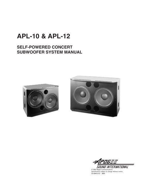
Table of ContentsPrecautions & Safety Notes . . . . . . . . . . . . . . . . . . . . . . . . . . 4Introduction. . . . . . . . . . . . . . . . . . . . . . . . . . . . . . . . . . . . . . . 7The Concept of Integration. . . . . . . . . . . . . . . . . . . . . . . . . . . 7AC Power Requirements . . . . . . . . . . . . . . . . . . . . . . . . . . . . 9Audio Signals . . . . . . . . . . . . . . . . . . . . . . . . . . . . . . . . . . . . . 14Controls . . . . . . . . . . . . . . . . . . . . . . . . . . . . . . . . . . . . . . . . . 15Amplifiers . . . . . . . . . . . . . . . . . . . . . . . . . . . . . . . . . . . . . . . . 16Installation . . . . . . . . . . . . . . . . . . . . . . . . . . . . . . . . . . . . . . . 17Signal Processing. . . . . . . . . . . . . . . . . . . . . . . . . . . . . . . . . . 18Using the <strong>APL</strong>-10/12 . . . . . . . . . . . . . . . . . . . . . . . . . . . . . . . 20Troubleshooting & Field Repairs . . . . . . . . . . . . . . . . . . . . . . 25Troubleshooting . . . . . . . . . . . . . . . . . . . . . . . . . . . . . . . . . . . 28Amplifier Back Panel . . . . . . . . . . . . . . . . . . . . . . . . . . . . . . . 29Specifications . . . . . . . . . . . . . . . . . . . . . . . . . . . . . . . . . . . . . 31Line Drawings. . . . . . . . . . . . . . . . . . . . . . . . . . . . . . . . . . . . . 32Warranty Information . . . . . . . . . . . . . . . . . . . . . . . . . . . . . . . IBC3
Precautions &Safety NotesEnglish• To reduce the risk of electric shock, disconnect the AC mains power cablebefore installing audio cable. Reconnect the power cord only after making allsignal connections.• Connect the loudspeaker only to a three-pole, three-wire grounding mainsreceptacle. The receptacle must be connected to a fuse or circuit breaker.Connection to any other type of receptacle poses a shock hazard and mayviolate local electrical codes.• Do not install the speaker in wet or humid locations without using weatherprotection equipment from <strong>Apogee</strong> <strong>Sound</strong>.• Do not allow water or any foreign object to get inside the loudspeaker. Donot put objects containing liquid on, or near, the unit.• To reduce the risk of overheating the loudspeaker, avoid exposing it todirect sunlight. Do not install the unit near heat-emitting devices or appliances,such as a room heater or stove.• The loudspeaker contains potentially hazardous voltages. Do not attempt todisassemble the unit. The unit contains no user-serviceable parts. Repairsshould be performed only by factory trained service personnel.Francais• Pour réduire le risqué d’électrocution, débrancher la prose principale del’haut-parleur, avant d’installer le cable d’interface allant à l’audio. Nerebrancher le bloc d’alimentation qu’après avoir effectué toutes les connections.• Branchez l’haut-parleur dans une prise de courant à 3 dérivations (deuxpôles et la terre). Cette prose doit être munie d’une protection adéquate(fusible ou coupe-circuit). Le branchement dans tout autre genre de prosepourrait entraîner un risqué d’électrocution et peut constituer une infractionà la réglementation locale concernant les installations électriques.• Ne pas installer l’haut-parleur dans un endroit où il y a de l’eau humiditéexcessive.• Ne pas laisser de l’eau ou tout objet pénétrer dans l’haut-parleur. Ne pasplacer decipients contenant un liquide sur cet appareil, ni à proximité deceluici.• Pour éviter une surchauffe de l’haut-parleur, conserver-la à l’abri du soleil.Ne pas installer à proximité d’appareils dégageant de la chaleur tells que radiateursou appareils de chauffage.4
• Ce haut-parleur contient des circuits haute tension présentant un danger.Ne jamais essayer de le démonter. Il n’y a aucun composant qui puisse êtreréparé par l’utilisateur. Toutes les reparations doivent être effectuées par dupersonnel qualifié et agree par le constructeur.Deutsch• Um die Gefahr eines slektrischen Schlages auf ein Minimum zu reduzieren,den Lautsprecher vom Stromnetz trennen, bevor ggf. Ein Audio-Schnittstellensignalkabel angeschlossen wird. Das Netzkabel erst nachHerstellung aller Signalverbindungen wieder einstecken.• Der Lautsprecher an eine geerdete zweipolige Dreiphasen-Netzsteckdoseanschließen. Die Steckdose muß mit einem geeigneten Abzweigschutz(Sicherung oder Leistungsschalter) verbunden sein. Der Anschluß der unterbrechungsfreienStromversorgung an einen anderen Steckdosentyp kann zuStromschlägen führen und gegen die örtlichen Vorschriften verstoßen.• Der Lautsprecher nict an einem Ort aufstellen, an dem sie mit Wasser oderübermäßig hoher Luftfeuchtigkeit in Berührung kommen könnte.• Darauf achet, daß weder Wasser noch Fremdkörper in das Innere denLautsprecher eindringen. Keine Objekte, die Flüssigkeit enthalten, auf oderneben die unterbrechungsfreie Stromversorgung stellen.• Um ein Überhitzen dem Lautsprecher zu verhindern, das Gerät vor direkterSonneneinstrahlung fernhalten und nicht in der Nähe von wämeabstrahlendenHaushaltsgeräten (z.B. Heizgerät oder Herd) aufstellen.• Im Inneren diesem Lautsprecher herrschen potentiell gefährlicheSpannungen. Nicht versuchen, das Gerät zu öffnen. Es enthält keine vomBenutzer reparierbaren Teile. Reparaturen dürfen nur von ausgebildetemKundenienstpersonal durchgeführt werden.Español• Para reducir el riesgo de descarga eléctrica, desconecte de la red el altoparlanteantes de instalar el cable de señalización de interfaz de la segnale. Vuelvaa conectar el conductor flexible de alimentación solamente una vez efectuadastodas las interconexiones de señalizatción.• Conecte el altoparlante a un tomacorriente bipolar y trifilar con neutro depuesta a tierra. El tomacorriente debe estar conectado a la protección dederivación apropiada (ya sea un fusible o un disyuntor). La conexión acualquier otro tipo de tomacorriente puede constituir peligro de descargaeléctrica y violar los códigos eléctricos locales.5
• No instale el altoparlante en lugares donde haya agua o humedad excesiva.• No deje que en el altoparlante entre agua ni ningún objeto extraño. Noponga objetos con líquidos encima de la unidad ni cerca de ella.• Para reducir el riesgo de sobrecalentamiento, no exponga la inidad a losrayos directos del sol ni la instale cerca de artefactos que emiten calor, comoestufas o cocinas.• Este altoparlante contiene niveles de voltaje peligrosos en potencia. Nointente desarmar la unidad, pues no contiene piezas que puedan ser repardaspor el usuario. Las reparaciones deben efectuarse únicamente por partedel personal de mantenimiento capacitado en la fábrica.6
Introduction<strong>Apogee</strong> Powered Loudspeaker Systems are highly-engineered products thatcombine advanced-technology amplifiers, sophisticated signal processing, andstate-of-the-art drivers housed in rugged, roadworthy loudspeaker enclosures.They are suitable for a wide variety of applications, ranging fromportable use for shows and events in all types of venues to permanent installationsin auditoriums, churches, theaters, stadiums, meeting rooms, boardrooms,and similar locations.The <strong>APL</strong>-10, and <strong>APL</strong>-12 are large format, high-powered subwoofers, capableof providing clean, undistorted low frequency sound at very high output levels.They form powerful arrays when used in multiples with like units. Theenclosures are designed for easy truck-packing and handling, and can be safelyflown from their built-in rigging points. They are designed to augment<strong>Apogee</strong>’s full-range powered speaker family, but they are equally effectivewhen used with conventional, non-powered loudspeakers. The <strong>APL</strong>-10 and <strong>APL</strong>-12 feature extended bass down to 34 Hz and 32 Hz, respectively,rapid transient response, and exceptionally low distortion, makingthem capable of fulfilling a wide range of professional sound reinforcementrequirements.<strong>Apogee</strong> powered products are exhaustively engineered and finely crafted.They will provide years of trouble-free service if care is taken in their use andmaintenance. It is recommended that you read this manual and retain it in aconvenient location for future reference.The Conceptof IntegrationWhy a Powered Loudspeaker?<strong>Apogee</strong>’s powered speaker systems further the concept of processor-basedloudspeakers. By combining advanced electronic signal processing with preciselymatched amplifiers and integrating this package into the speaker enclosureitself, a number of engineering improvements result. Some of these are:• The internal signal processor corrects driver and enclosure anomalies, andprovides required crossovers, time-domain alignment, and protection circuits.• The amplifier’s power output, headroom, frequency response, and dynamicrange are optimized for each model of loudspeaker system.• The gain structure of the signal processor and amplifiers are always perfectlymatched.• The amplifier output cables are kept to very short lengths, thereby reducingcable losses to nearly zero.7
These engineering advancements result in the following benefits:• All aspects of the loudspeaker system’s performance are maximized. Sonicquality, power output capability, flatness of response, distortion, and behaviorunder abusive conditions meet remarkably high standards.• Reliability is increased because the internal amplifiers deliver appropriatepower levels to the drivers, without danger of over-powering or underpowering.• Setup is quick and easy - all key circuitry is self-contained and factory-interconnected.There is no longer a need for the time-consuming mounting andwiring of processors and amplifiers in outboard rack enclosures.• Powered speakers save valuable truck and stage space previously allocatedfor amplifier racks. Load-ins and load-outs are quicker and easier than withconventional systems.• Powered speakers weigh less than equivalent non-powered speakers andamp racks, resulting in easier handling and reduced shipping costs.• Powered speakers cost less and offer higher value than the equivalent nonpoweredspeaker, processor, amplifier, and rack combination.8
AC PowerRequirements(1) AC Power Connector and CableThe <strong>APL</strong>-10/12 speakers use a PowerCon ® 3-pole AC mains connector fortheir power inlet (see Figure #1). When joined to the mating PowerConconnector supplied with the AC line cord, the connector pair locks in placeto prevent inadvertent disconnection. PowerCon connectors are durable,inexpensive, and readily obtainable.Figure 1The AC PowerCon cable assembly provided with your <strong>APL</strong>-10/12 is equippedwith an AC mains plug compatible with the power service in the country ofsale. If you need to change this plug or to construct special purpose powercables, the wiring must follow the convention shown in Figure #2.Black or Brown - LineFigure 2White or Blue - NeutralGreen/Yellow - Earth Ground9
LineGroundFigure 3NeutralInterior of PowerCon connector showing the wiring terminalAll AC power plugs must always be of the 3-pole grounding type.DO NOT DEFEAT THE GROUND CONNECTION BY USINGAN AC GROUND LIFT ADAPTER, OR BY CUTTING THEGROUND PIN OF THE AC POWER PLUG.(2) Voltage RangeThe <strong>APL</strong>-10/12 speakers use advanced, high efficiency, intelligent power supplies.A convenient external switch allows for easy conversion between 115VAC and 230V AC. In the 115V AC setting, the allowable line voltage range is90V AC to 132V AC and in the 230V AC setting, the allowable range is 190VAC to 265V AC.NOTE: The 115V AC model is suitable for use at 100V AC with only a smallreduction in power capability.Before applying power, carefully check the Line Voltage Switch Position on therear panel located by the AC Mains Power Input connector to insure compatibilitywith the local AC mains supply.Voltages above the rated maximum should be avoided at all times or damagemay occur!10
(3) Current RequirementsAll power amplifiers require sufficient current for proper operation and theamplifiers designed into <strong>Apogee</strong> powered loudspeakers are no exception.Chart #1 shows the required current for one <strong>APL</strong>-10 or <strong>APL</strong>-12 at threestandard international working voltages (120, 240, & 100V AC). Because currentdrain is ultimately a function of the program source, Chart #1 showsboth the theoretical maximum, and what can be expected under typical highlevelprogram conditions:<strong>APL</strong>-10 / <strong>APL</strong>-12100 / 120V AC10.5A RMS7A RMS (OR LESS)240V ACChart 1Max. Continuous Amperes5.25A RMS3.5A RMS (OR LESS)Typical Program ConditionsWe recommend powering no more than one <strong>APL</strong>-10 or one <strong>APL</strong>-12 from asingle 20A, 120V AC circuit, and no more than two <strong>APL</strong>-10 or <strong>APL</strong>-12 speakersfrom a single 20A, 240V AC circuit, thereby allowing a margin for line lossand/or lower than normal voltages.To determine the total current requirement for a system of powered loudspeakers,simply add their Maximum Continuous RMS Currents together,then calculate a safety margin of 25% or greater.If special length AC cables are required for your powered speakers, theyshould be constructed of durable, high-quality portable cordage such as S,SO, or SJO type.Chart 2 provides the basic guidelines of The National Electric Code for fourcommon gauges of copper wire related to permissible load in amperes.11
Chart 2 applies to three-conductor portable cordage of the types S, SO, SP,SPT, SJ, and SJO, which are typically rated at a maximum operating temperatureof 140°F (60° C). (NOTE: Operating temperature is the heat generatedwithin the cable from the voltage drop added to the ambient temperature.)Chart 2 covers ambient temperatures of 86°F (30°C), 104°F (40°C), & 122°F(50°C).For safety reasons, the maximum ratings in the table below should never beexceeded.Chart 2Ambient TemperatureAWG# 86°F (30°C) 104°F (40°C) 122°F (50°C)141210815 A20 A25 A35 A12.3 A16.4 A20.5 A28.7 A6.9 A8.7 A14.5 A20.3 A(NOTE: AWG means American Wire Gauge.)As you can readily see from Chart 2, the maximum permissible current ratingsdecrease rapidly as the ambient temperature rises. Carefully considerthe ambient temperature in which the equipment will be used when determiningappropriate wire gauge size.(4) Voltage DropAnother important consideration in determining appropriate wire gauge isthe voltage drop that occurs across the cable’s resistance. This is a functionof the gauge and the length of the conductors, the current drawn by the load,and the AC mains voltage. Generally speaking, the permissible voltage dropshould not exceed 2.5% of the working voltage for audio loads. Chart 3shows voltage drop as a percentage of the nominal working voltage for typicallengths of cables in #14 AWG, #12 AWG, #10 AWG, and #8 AWG at120V AC and 240V AC. The shaded areas show cable lengths and loads thatresult in 2.5% or less of voltage drop.12
POWER CABLE VOLTAGE DROP (IN PERCENTAGE OF NOMINAL VOLTAGE)Chart 3#14 AWG, 120V AC #14 AWG, 240V ACLength in Feet 5A 10A 15A 20A Length in Feet 5A 10A 15A 20A25' 0.6% 1.2% 1.8% 2.4% 25' 0.3% 0.6% 0.9% 1.2%50' 1.2% 2.4% 3.6% 4.9% 50' 0.6% 1.2% 1.8% 2.4%75' 1.8% 3.6% 5.5% 7.3% 75' 0.9% 1.8% 2.7% 3.6%100' 2.4% 4.9% 7.3% 9.7% 100' 1.2% 2.4% 3.6% 4.9%125' 3.0% 6.1% 9.1% 12.2% 125' 1.5% 3.0% 4.6% 6.1%150' 3.6% 7.3% 10.9% 14.6% 150' 1.8% 3.6% 5.5% 7.3%175' 4.3% 8.5% 12.8% 17.0% 175' 2.1% 4.3% 6.4% 8.5%200' 4.9% 9.7% 14.6% 19.5% 200' 2.4% 4.9% 7.3% 9.7%225' 5.5% 10.9% 16.4% 21.9% 225' 2.7% 5.5% 8.2% 10.9%250' 6.1% 12.2% 18.2% 24.3% 250' 3.0% 6.1% 9.1% 12.2%275' 6.7% 13.4% 20.1% 26.8% 275' 3.3% 6.7% 10.0% 13.4%300' 7.3% 14.6% 21.9% 29.2% 300' 3.6% 7.3% 10.9% 14.6%#12 AWG, 120V AC #12 AWG, 240V ACLength in Feet 5A 10A 15A 20A Length in Feet 5A 10A 15A 20A25' 0.4% 0.8% 1.1% 1.5% 25' 0.2% 0.4% 0.6% 0.8%50' 0.8% 1.5% 2.3% 3.1% 50' 0.4% 0.8% 1.1% 1.5%75' 1.1% 2.3% 3.4% 4.6% 75' 0.6% 1.1% 1.7% 2.3%100' 1.5% 3.1% 4.6% 6.1% 100' 0.8% 1.5% 2.3% 3.1%125' 1.9% 3.8% 5.7% 7.7% 125' 1.0% 1.9% 2.9% 3.8%150' 2.3% 4.6% 6.9% 9.2% 150' 1.1% 2.3% 3.4% 4.6%175' 2.7% 5.4% 8.0% 10.7% 175' 1.3% 2.7% 4.0% 5.4%200' 3.1% 6.1% 9.2% 12.3% 200' 1.5% 3.1% 4.6% 6.1%225' 3.4% 6.9% 10.3% 13.8% 225' 1.7% 3.4% 5.2% 6.9%250' 3.8% 7.7% 11.5% 15.3% 250' 1.9% 3.8% 5.7% 7.7%275' 4.2% 8.4% 12.6% 16.8% 275' 2.1% 4.2% 6.3% 8.4%300' 4.6% 9.2% 13.8% 18.4% 300' 2.3% 4.6% 6.9% 9.2%#10 AWG, 120V AC #10 AWG, 240V ACLength in Feet 5A 10A 15A 20A Length in Feet 5A 10A 15A 20A25' 0.2% 0.5% 0.7% 1.0% 25' 0.1% 0.2% 0.4% 0.5%50' 0.5% 1.0% 1.4% 1.9% 50' 0.2% 0.5% 0.7% 1.0%75' 0.7% 1.4% 2.2% 2.9% 75' 0.4% 0.7% 1.1% 1.4%100' 1.0% 1.9% 2.9% 3.8% 100' 0.5% 1.0% 1.4% 1.9%125' 1.2% 2.4% 3.6% 4.8% 125' 0.6% 1.2% 1.8% 2.4%150' 1.4% 2.9% 4.3% 5.8% 150' 0.7% 1.4% 2.2% 2.9%175' 1.7% 3.4% 5.0% 6.7% 175' 0.8% 1.7% 2.5% 3.4%200' 1.9% 3.8% 5.8% 7.7% 200' 1.0% 1.9% 2.9% 3.8%225' 2.2% 4.3% 6.5% 8.7% 225' 1.1% 2.2% 3.2% 4.3%250' 2.4% 4.8% 7.2% 9.6% 250' 1.2% 2.4% 3.6% 4.8%275' 2.6% 5.3% 7.9% 10.6% 275' 1.3% 2.6% 4.0% 5.3%300' 2.9% 5.8% 8.7% 11.5% 300' 1.4% 2.9% 4.3% 5.8%#8 AWG, 120V AC #8 AWG, 240V ACLength in Feet 5A 10A 15A 20A Length in Feet 5A 10A 15A 20A25' 0.2% 0.3% 0.5% 0.6% 25' 0.1% 0.2% 0.2% 0.3%50' 0.3% 0.6% 0.9% 1.2% 50' 0.2% 0.3% 0.5% 0.6%75' 0.5% 0.9% 1.4% 1.8% 75' 0.2% 0.5% 0.7% 0.9%100' 0.6% 1.2% 1.8% 2.4% 100' 0.3% 0.6% 0.9% 1.2%125' 0.8% 1.5% 2.3% 3.0% 125' 0.4% 0.8% 1.1% 1.5%150' 0.9% 1.8% 2.7% 3.6% 150' 0.5% 0.9% 1.4% 1.8%175' 1.1% 2.1% 3.2% 4.2% 175' 0.5% 1.1% 1.6% 2.1%200' 1.2% 2.4% 3.6% 4.8% 200' 0.6% 1.2% 1.8% 2.4%225' 1.4% 2.7% 4.1% 5.5% 225' 0.7% 1.4% 2.0% 2.7%250' 1.5% 3.0% 4.5% 6.1% 250' 0.8% 1.5% 2.3% 3.0%275' 1.7% 3.3% 5.0% 6.7% 275' 0.8% 1.7% 2.5% 3.3%300' 1.8% 3.6% 5.5% 7.3% 300' 0.9% 1.8% 2.7% 3.6%13
It’s useful to note the benefit of operating a powered loudspeaker system athigher voltages (when possible). At 240V AC, current consumption is halfthat of 120V AC and the resultant voltage drop for a given cable size andlength decreases by a factor of 4. This means that the cable can be four timeslonger when used at 240V AC than at 120V AC. Higher voltages aremore efficient!Audio Signals(1) Input Impedance and LevelThe <strong>APL</strong>-10/12 speakers were designed to receive a balanced-line signal ontheir 3-pin female XLR type connector. They are also equipped with a 3-pinMale XLR output connector, labeled “looping output,” intended for the purposeof daisy-chaining multiple powered speakers together on a common signalfeed. These input and output connectors are hard-wired in parallel; that isto say, no active or passive buffer exists between the two connectors, theyare simply wired in parallel. This means that the loop-through connector willalways remain functional, even if AC power is interrupted to a speaker“upstream” of other speaker(s) on the same feed circuit.The input impedance is 35k-ohm, active balanced, and is intended to receivea nominal +4 dBv input level (+4 dBv = full power). Because it’s common practiceto loop quite a few powered speakers together on a shared feeder circuit,care must be taken to insure that the signal source is capable of drivingthe group of powered loudspeakers. For example, ten <strong>APL</strong>-12 speakers presenta 3.5k-ohm load to the signal source. This is well within the capability ofmost line-level output drivers, but depending on the output impedance of thesource, some loss in level may occur. The formula to calculate such loss is:RR S Voltage Loss (dB) = 20 * Log [Ix( R Ix + R S )]V S R IxV IWhere: R S = Source Equipment Output ImpedanceR Ix= Combined Input Impedance of all <strong>APL</strong> SpeakersNote: V S = Unloaded Source Equipment Signal VoltageV I = Loaded Signal Input Voltage to <strong>APL</strong> SpeakersFor example, let’s say you’re driving ten <strong>APL</strong>-12 speakers with a 100-ohmsource impedance. The formula to calculate loss would then be:NOTE: It is important to be aware of the potential losses that may occurfrom combining multiple powered speakers on the same feed circuit. This isparticularly important when attempting to adjust audio levels among a largesystem that employs multiple feed circuits with different numbers of poweredspeakers on each feed.14
(2) Input and Output ConnectorsThe input and output connectors are wired as follows:XLR Pin #FunctionPin 1Earth & Chassis GroundPin 2 Signal + DIFFERENTIAL INPUTPin 3 Signal - DIFFERENTIAL INPUTConnector Case Earth & Chassis GroundA positive signal applied to pin 2 of the XLR will result in a positive acousticpressure wave (excursion) appearing at the front of the drivers in the speakersystem. Conversely, a positive signal appearing at pin 3 of the XLR willresult in a negative acoustic pressure wave (recursion) appearing at the frontof the speaker system’s drivers.Controls(1) Level ControlA single level control is located just above the XLR input. Under normal circumstances,the level control should be turned fully clockwise to the 0 position.This is full gain, or 0 dB of attenuation. In certain environments, forexample, very quiet productions, it may be desirable to reduce the gain of thepowered speaker to improve the overall gain structure of the entire audiosystem and possibly reduce system noise slightly. This is easily achieved byturning the level down to the desired amount of attenuation.When multiple speakers will be attenuated, it is best to count the detentpositions as the level control is adjusted. By doing this, you will be able toaccurately set each speaker to exactly the same attenuation.It is important to confirm that the level is set appropriately before deployingthe speaker into a location where it will be difficult to reach.(2) Mute ControlEach channel of the internal amplifier has a user accessible mute button.Muting the LF1 or LF2 amplifier output can be useful in troubleshooting asystem. The two buttons are labeled Ch1 and Ch2. Channel 1 is the LF1 ampand Channel 2 is the LF2 amp. Mute is enabled when the button is out. It isimportant to confirm that both buttons are depressed (un-muted) beforedeploying the speaker into a location where it will be difficult to reach inorder to un-mute a channel.15
(3) IndicatorsThe <strong>APL</strong>-10/12 speakers have a green LED labeled PWR (Power) that indicatesAC mains power is applied and the power supplies are functioningproperly. A green Signal LED is above the level control. An amber LED justabove the power LED indicates clipping. A red LED labeled PROT (Protect)is provided to indicate that the amplifier has gone into protect mode. Protectmode occurs under the following conditions:(a) The amplifier has exceeded its maximum safe operating temperature (theamplifier will automatically reset after cooling down).(b) The amplifier has failed and is outputting DC voltages that could damagethe driver(s), or DC is present upstream of the amplifier due to componentfailure in the processor.(c) The driver(s) may have failed causing the amplifier to produce excessiveoutput voltage.(d) The amplifier has failed to pass its automatic internal start-up test.If conditions b, c, or d are encountered, the amplifier will latch in the Protectmode until the power is cycled to force a reset. However, if the fault conditionhas not been repaired upon power-up, the amplifier will again enter intothe Protect mode.Amplifiers(1) OverviewThe internal amplification package in both the <strong>APL</strong>-10 and -12 consists ofdual, fully-independent amplifiers. Each amplifier is capable of delivering over1200 watts of music power.These amplifiers and power supplies use numerous, proprietary design featuresthat result in extremely low distortion, high reliability, and a very lowheat by-product. No fans are used or needed, eliminating the risk of amechanical device becoming noisy during a quiet performance due to bearingwear or contamination. The absence of fans also greatly simplifies maintenance,by eliminating the need to regularly check and clean air intake filters.The unique design of the amplifiers also results in the ability to provideexceptional transient response. This equates to a wider dynamic range andmore low-frequency “punch” than that of conventional amplifiers of a similarpower rating.16
InstallationWhen installing and using the <strong>APL</strong>-10/12, some simple precautions should befollowed. These include:(1) Maintain Proper Air FlowThe <strong>APL</strong>-10/12 speakers are radiant- and convection-cooled devices. The aluminumheat-exchanger mounted on the rear surfaces provides primary coolingof the system. Care must be taken to locate the units away from heat registers,heat-generating appliances, lighting equipment, and any other apparatusthat could raise the temperature of the nearby air.The <strong>APL</strong>-10/12 speakers require unimpeded air circulation in order to functionproperly (this is especially important when multiple units are used instacked and/or tight-pack configurations). The <strong>APL</strong>’s rear surface should belocated at least 18" away from walls and/or ceilings. Lamps, especially of thehigh intensity or theatrical type, should never be allowed to shine directly onthe heat exchanger.(2) Ambient TemperatureThe <strong>APL</strong>-10/12 speakers are designed to be used in ambient temperaturesranging from 32°F - 113°F (0°C - 45°C). Higher or lower temperaturescould cause system shutdown or result in early component failure. Whenused outdoors on a hot day, take precautions to avoid direct sunlight on therear heat exchanger. Direct, intense sunlight can raise the temperature of theheat exchanger to a point where the amplifiers may be required to shutdownto avoid permanent damage.(3) More About Heating and CoolingThe <strong>APL</strong>-10/12 speakers have a relatively complex thermal dynamic system.They contain several heat sources (amplifiers, power supplies, and drivers)that generate significant heat but only when program material is being reproduced.They are cooled primarily through heat radiation from the rear panelas well as by convection; and secondarily, by a small degree of air movementgenerated by the cone drivers.Because the heat output of the system is directly proportional to the durationand nature of the program material, the system may not reach thermalstability for several hours after it is activated. For this reason, it is importantto test the system under actual conditions of use if questionable conditionsare present. Questionable conditions include:(a) ambient temperature at or above the maximum rating(b) intense sunlight or artificial light shining on the heat exchanger(c) program material that runs for many hours without pause(d) combinations of the above17
Here’s a hypothetical example of what to look out for. An <strong>APL</strong>-12might be set up outdoors in 85°F (29°C) temperature with sunlight shiningpartially on the rear panel. Let’s assume it is tested during a 30-minute soundcheck and all is well. Later that day, the ambient temperature rises to 99°F(37°C) and the sunlight is now shining directly on the rear of the loudspeaker.The show starts, featuring dance tracks with no pause between song titles.Under such extreme conditions, it is entirely possible that after a period ofservice, the loudspeaker will shut off to protect itself from excessive heat.Problems, such as the one described above, can be avoided by shading theheat exchanger from direct sunlight.Signal Processing(1) Basic ConceptThe <strong>APL</strong>-10/12 speakers use a highly-advanced signal processor containedentirely within the unit. The processor provides the functions of an asymmetricalelectronic crossover (36 dB/octave low-pass and 24 dB/octave highpass),fixed equalization to compensate for driver/enclosure anomalies, andadvanced protective limiting circuits. It also provides a low-frequency alignmentcircuit that acts synergistically with the enclosure’s ports. This serves toextend the bass response well below that of a conventional enclosure of asimilar size. All circuits in the audio path utilize the highest quality, most upto-datesemi-conductor technologies available today.The processor is the key to the extraordinary sound quality of the loudspeakersystem. Unlike generic crossovers, either digital or analog, the <strong>APL</strong>processor was carefully designed in tandem with the drivers and the enclosure,to provide optimum performance.(2) Driver ProtectionThe <strong>APL</strong>-10/12 speakers utilize a special, highly-evolved set of limiter parametersand controls. Multiple limiters are used simultaneously with attack,release, integration time, and slopes that have been carefully matched to theindividual speakers thermal and mechanical limits over time.All of this occurs without compromising dynamic range or otherwise unnaturallycompressing the program material. The protection circuits only actwhen the drivers would otherwise be damaged and, therefore, are exceptionallytransparent. They are effectively “out of circuit” when below thethreshold of engagement. The result is extremely clean sound quality, witheffective protection of potential damage to the drivers under abusiveconditions.18
A clipping LED indicator is located on the rear panel. This LED will illuminatewhen the speaker is several dB into limiting and indicates maximum operatinglevel has been reached. It is not uncommon to see the LED illuminate regularly,such as on downbeats and crescendos.If the LED appears to be "ON" more than "OFF" (i.e., if they are continuouslyflashing or glowing at a steady state), the loudspeaker system is being pushedtoo hard for its size and power output capability. To correct this, reduce thedrive level to the speaker system, or install additional speakers to achieve theSPL (<strong>Sound</strong> Pressure Level) required for the application.(3) A Word About LimitersProperly designed protective limiters can do wonders to help prevent driverdamage and extend normal driver life, but are by no means a panacea.<strong>Apogee</strong> limiters do not exhibit “brick-wall” characteristics, as these type oflimiters seriously degrade sound quality. <strong>Apogee</strong>’s intelligently engineeredlimiter circuits provide an excellent measure of protection, while maintainingsonic purity.These limiter circuits are capable of effectively reducing program levels thatwould otherwise damage the system’s drivers. This takes place with little orno loss of sonic quality or dynamic range, because the circuits are designedso that they only engage when driver non-linearity or driver damage wouldotherwise occur. However, when a limiter is pushed well past its threshold ofengagement to the point where it is continually “in circuit”, by nature, itincreases the duty-cycle of the program material. This happens because, asthe limiter decreases peak amplitudes, RMS values increase, causing the driversto heat beyond normal. Additional circuits could be employed to reducelevels and “clamp” the output of the system, but such circuits would representa high level of intervention and be very audible in their action. The propersolution is for the operator to recognize that the system is being pushedpast its capabilities and either reduce operating levels or add additionalspeaker systems to provide the desired <strong>Sound</strong> Pressure Level (SPL).19
Using the<strong>APL</strong>-10/12(1) OverviewThe <strong>APL</strong>-10/12 can be used in many ways and for many applications. In itssimplest form, one <strong>APL</strong>-10/12 placed at each side of the stage will add dramaticlow frequency impact to a typical full-range system in a club, church, ortheatre.A full-blown array of fifty or sixty <strong>APL</strong>-10/12 speakers, properly positioned,can provide intense low-frequency power for large-scale concerts, bothindoors and out.The nature of low-frequency sound waves and how they behave in spaceshould be understood, at least in rudimentary form, to operate an <strong>APL</strong>-10/12system to your best advantage. Low frequency waves are very long. A 30 Hzwavelength is approximately 35 feet in length and a 100 Hz wavelength isapproximately 11.3 feet in length (varying a bit with temperature).Because low-frequency waves are significantly greater in length than higherfrequency waves, they behave quite differently than other wavelengths.First, a long waveform does not ‘see’ a small or moderate-sized obstructionas an obstacle; it simply diffracts around the barrier as if it’s not there.Second, the substantial length of low frequency waves makes it difficult to distinguishtheir source direction. (This is why a single subwoofer can often beused to augment a stereo pair of full-range speakers, without sacrificingstereo separation and image.)Third, low frequency waves tend to join together very graciously (if they arein phase and in time with one another), even if their sources are separatedby a considerable distance. Most professional sound engineers have experiencedan intense bass elevation in the middle of certain rooms, generated bya stack of speakers placed at either side of the stage.Understanding how low-frequency waves transmit can be very helpful inplanning and designing optimum sound systems. There are many useful textsavailable on this subject. Recommended reading: "Fundamentals of <strong>Sound</strong>"and "Psychoacoustics" by F. Alton Everest in the "Handbook for <strong>Sound</strong>Engineers" published by Howard Sams & Co.To help you get the most from your <strong>APL</strong>-10/12 powered loudspeakers, hereare some basic guidelines.(2) PlacementThe <strong>APL</strong>-10/12 will benefit greatly in terms of power output by being placedadjacent to a boundary surface (or surfaces). In practical terms, this meansputting the <strong>APL</strong>-10/12 on the floor, on the ground, by a rear wall or ceiling(being careful not to restrict air flow to the heat exchanger), or in a corner.20
When located by a wall (half space), power output will increase by 3 dB (seeFigure 4) when compared to placement in a free-field environment (seeFigure 5). When located at the junction of two walls (quarter space), poweroutput will increase by 6 dB over that of a free-field environment (see Figure6). Finally, when located at the junction of three walls (eighth space), poweroutput increase a full 9 dB (see Figure 7).It’s not always possible to utilize walls and corners for extra power. Thenearest wall or corner might result in the subwoofer being positioned behindthe microphones, causing feedback, or, too far out of time sync with the fullrangespeakers. Sometimes the sound quality from a subwoofer located in acorner is not desirable due to other aspects of the room’s acoustics.However, when wall and corner positions are appropriate to use, they offera tremendous increase in power output.Figure 4 - Half SpaceFigure 5 - Free Spacell3dB0dBFigure 6 - Quarter SpaceFigure 7 - Eighth Space6dBll9dB21
(3) Configurations of Multiple UnitsWhen the <strong>APL</strong>-10/12 is used in multiples, certain techniques can be appliedto help achieve the desired results. To start with, the enclosures should beplaced touching one another. Separating them, even a little, limits their powersummation and can generate lobes and unwanted response anomalies.Multiple units configured in a line will exhibit increased directionality in theaxis of the line. For example, placing four or more <strong>APL</strong>-10/12 speakers horizontallyend-to-end narrows their horizontal coverage pattern withoutchanging the vertical pattern (NOTE: dispersion is essentially omni-directionalfor a single unit). Such a configuration can be used to increase the coveragedistance in a large venue, such as a deep shed. Conversely, stacking four<strong>APL</strong>-10/12 speakers in a vertical line will narrow their vertical coverage anglewithout changing their horizontal dispersion. This configuration could be usefulto penetrate long distances in a flat outdoor space, such as a soccer field.RULE OF THUMB: Whenever the coverage angle is narrowed, on-axis poweris also increased. The greater the number of enclosures placed in a line, thenarrower the dispersion angle will be, with a corresponding increase in summationand forward-radiated power. The lowest frequency that will exhibitsuch behavior is directly a function of the array size.The length of the array must be at least a 1/4 wavelength of the frequency ofinterest for any semblance of directional control to occur. At 1/2 wavelength,directional control starts to become effective. As the length of the line grows,directional control (i.e., narrowing of the dispersion pattern) increases continually,becoming more and more effective.Chart 4 depicts wavelength vs. frequency (at ISO preferred frequencies)throughout the operating range of the <strong>APL</strong>-10/12, in relation to the numberof <strong>APL</strong>-10/12 speakers that would approximate a 1/2 wavelength of the frequencyof interest when arrayed end-to-end and top-to-bottom.<strong>APL</strong>-10<strong>APL</strong>-12Frequencyin HzWavelengthfeet / metersNo. end-to-end/No. top to bottomNo. end-to-end/No. top to bottomChart 42531.64050638010044.8 / 13.735.6 / 10.928.3 / 8.622.5 / 6.917.9 / 5.414.2 / 4.311.3 / 3.49 / 127 / 9.55 / 7.54 / 63.5 / 53 / 42 / 36 / 95 / 74 / 63 / 4.52 / 3.52 / 32 / 222
<strong>APL</strong>-10/12 speakers can also be combined in an L-format (See Figure 8). TheL-format exhibits directional control in both axes, and is often the bestchoice for deploying a large number of speakers in sizeable venues.Figure 8Finally, <strong>APL</strong>-10/12 speakers can be configured into a block arrangement (SeeFigure 9). This arrangement also exhibits directional control in both axes, butit does not take full advantage of the boundary surface effect (see "Using the<strong>APL</strong>-10/12 – (2) Placement" (pg. 20). Although this configuration is certainlymore effective than scattering the units about at random, it has a tendencyto produce unwanted lobing, sometimes leading to a muddy bass response.Figure 923
(4) Flying the <strong>APL</strong>-10/12For many applications, the <strong>APL</strong>-10/12 subwoofer may need to be flown. Thiscommonly occurs with television award shows, political conventions, andother events where the audience is located too close to the stage to allowthe subwoofers to be placed in the typical side or front-of-stage position.<strong>APL</strong>-10/12 speakers perform perfectly well when flown; in fact, the soundquality is often perceived as being superior when the speakers are in the airas opposed to on the ground. This is usually because they integrate betterwith the flown full-range speakers when they are in close proximity to them,although it can also be because of the acoustical characteristics of a givenroom, or a combination of both. However, be aware that the same numberof units that performed satisfactorily on the ground or in a corner will haveto be doubled or tripled to achieve the same power output level when theyare flown.The <strong>APL</strong>-10 and -12 are equipped with four rigging points – two on the topand bottom of the <strong>APL</strong>-10 – and two on either side for the <strong>APL</strong>-12. Thesepoints are supplied with either <strong>Apogee</strong> nutplates or Aeroquip pan-fittings, asspecified at purchase (fitting types can be changed easily in the field to accommodatechanging requirements). If the rigging fittings are to be changed, alwaysuse the screws that are supplied from the factory – never use generic screwspurchased at a hardware store because they are unsafe for this application!Nutplates are circular steel plates with a welded 3/8-16 threaded fastener inthe center, designed to accept 3/8-16 threaded bolts (also available in MetricM-10 version). Each nutplate can sustain a straight-line-of-force load of 2500lb. (1136 kg) before failure. An <strong>APL</strong>-12 weighs 214 lb. (97 kg), so if only twonutplates are used to suspend the speaker, the safety factor is 23:1 (NOTE:OSHA requires a 5:1 safety factor, whereas most theatrical rigging shops havevoluntarily adopted a 7:1 safety factor.).It is vitally important that all hardware used to suspend the <strong>APL</strong>-10/12 be ofthe highest grade materials and construction. All bolts must be SAE Grade 7or better. The American bolt-grade rating system is often depicted by a numberof linear hash marks on the head of the bolt – five marks mean Grade 7,six marks mean Grade 8.If eyebolts are used, they must be forged and of the shoulder-type. Eyeboltsare designed for a straight-line-of-force. They de-rate rapidly and becomeunsafe as the load angle deviates from the 0 degree axis (in line with thelength of the threaded bolt).All bolts must be tightened securely, but not over-tightened (5-7 ft. lb. oftorque is generally sufficient for 3/8" bolts). Over-tightening can cause muchof the tensile strength of the bolt to be used up, before any external load isplaced on it. An exception to this rule is when the bolt is used in sheer, suchas when rigging plates are attached to the side of a speaker. In sheer, the frictionprovided by tightening and preloading the bolt actually increases thestrength of the joint and decreases cyclic failure of the fastener.24
Consult an experienced rigger or engineer when it comes to riggingpractices, methods, required materials, or other details. Thekinetic energy from a 214 lb. object falling 40 feet onto a solid surface is trulyastounding. Injury or loss of life could occur, even to those who are not inclose proximity, let alone the injuries or deaths that may result from a panickedcrowd. Safety is the most important part of the job! Take the extra timeto obtain the proper rigging materials and components, or keep the system onthe ground! All rigging fittings, slings, Spansets, shackles, bolts, and otherequipment should be inspected carefully before each use. Questionable componentsor materials should immediately be discarded where they won’t befound and re-used by someone else. In particular, forged eyebolts, shackles,pins, and other high-carbon steel components are susceptible to fracture, ifthey fall even a few feet onto a hard surface like a concrete floor. Play it safeand do not use any questionable components or materials!Troubleshooting &Field Repairs(1) GeneralTroubleshooting the <strong>APL</strong>-10/12 is a simple process. With an integrated system,there’s really not much that can go wrong. If a problem does arise, itusually can be solved quickly by performing the processes described below.All repair work that involves dismantling the <strong>APL</strong>-10/12 must be performedby a qualified, trained service technician. The power cable must be disconnectedbefore attempting any repair work. Lethal voltages are present insidethe <strong>APL</strong>-10/12 when the power cable is connected!(2) DriversThe <strong>APL</strong>-10 employs dual 15" high power cone drivers and the <strong>APL</strong>-12, dual18" high power cone drivers. All are treated with Ferrofluid as a dampeningand heat conduction agent. Additionally, the cone surfaces are treatedwith a proprietary compound that makes them highly resistant to waterdamage. This compound has an important secondary purpose: the cones willnot change mass due to moisture absorption in humid weather, making thesystem’s sonic qualities exceptionally stable when used in varying climacticconditions.Occasionally, due to mechanical shock or abusive operation, a driver maybecome dysfunctional. Drivers can fail completely, or they can fail in such away that they continue to reproduce sound but their output becomesnoticeably distorted. The latter is usually due to deformation of the voicecoil, resulting in the coil rubbing against the gap. In either case, driver replacementis warranted.25
To verify if a driver has failed, remove the front grille and listen to the systemat a moderate level. By lightly touching each driver while playing programmaterial, you can readily tell if it is actively radiating or passively respondingto the other driver’s pressure.Before attempting to replace any parts in the <strong>APL</strong>-10/12, be certain to disconnectthe power cable from the unit. Lethal voltages are present inside theenclosure when the unit is connected to an AC mains supply!The drivers in the <strong>APL</strong>-10/12 can be changed in just a few minutes. To gainaccess, first remove the front protective grille with a Phillips screwdriver.After the grille is removed, the driver itself can be removed by simply looseningthe eight (8) Allen-drive fasteners that retain it, and lifting it out of theenclosure. If possible, perform this task with the enclosure resting on its rearsurface. This will ease the process and minimize the force that would otherwisebe placed on the driver as the fasteners are loosed, if the enclosurewere upright. To remove the driver after the eight Allen-drive fasteners havebeen taken out, reach through the nearest bass port with your hand and pushthe driver upwards. The gasket sometimes sticks a bit, so do not hesitate touse a little force to unseat the driver from the gasket.Once the driver has been removed from the enclosure, disconnect thespeaker wires from the terminals. To replace the driver, simply reverse thedisassembly process, making sure to connect the speaker wires properly. Theblack wire goes to the black terminal on the driver, and the red or white wiregoes to the red terminal on the driver.NOTE: If the driver is connected backwards (out of phase), it will not functionproperly and could be damaged rapidly. It could also damage the otherdriver in the enclosure.After the driver is connected, place it carefully over the opening and rotateit to align its holes with the eight threaded inserts in the enclosure. Then,install the fasteners, being careful to tighten them gradually in a cross-patternso as to equalize the force placed on the driver’s rim. Do not over-tightenthe fasteners or the driver’s rim may become warped! Two to three footpoundsof torque is sufficient.After replacing the driver, power up the speaker system and play some programmaterial through it before replacing the grille. Verify that the new driveris operating properly. If the system still exhibits problems, it may needadditional service work.26
(3) Amplifier Removal & ReplacementBefore attempting service work, be certain to disconnect the power cablefrom the unit. Lethal voltages are present inside the enclosure when the unitis connected to an AC mains supply!The amplifier package consists of the power supply, amplifiers, and processingelectronics. It is held in place by twelve (12) 8/32 Phillips drive fasteners.Once the fasteners are free, the amplifier assembly can be easily disconnectedfrom the drivers. All other cables and connections are contained withinthe assembly. The entire assembly can be replaced in a matter of minutes byreversing the removal process. Make sure to tighten the fasteners graduallyin a cross-pattern, to avoid warping the enclosure material.27
TroubleshootingPROBLEMSUGGESTIONSPOWER LED illuminates butaudio is not present• Check to be sure that the signal feed cable has audio present.This can be done by plugging it into a speaker/amplifier that isknown to work, or, by using a portable poweredheadphone/amplifier test set such as the Shure FP22.• Make sure the signal feed cable is securely mated with theXLR input connector.• Substitute an alternate cable to determine if the cable is atfault.• Disconnect the input cable. If the hum or noise ceases, theproblem is either in the source, or it may be caused by aground loop created when the source is connected to the <strong>APL</strong>-10/12. Listen to the source with an alternate speaker/amplifieror a headphone test set, to determine if the source is clean.The system exhibits hum or noise• If the source is clean, try installing an XLR ground lift adapterto the input cable.DO NOT, UNDER ANY CIRCUMSTANCES,ATTEMPT TO LIFT THE AC GROUND CON-NECTION! LIFTING THE AC GROUND COULDRESULT IN INJURY OR DEATH!The audio sounds compressed ordistorted and the limit light isNOT registering.• Check the input source with an alternate speaker/amplifier ora headphone test set, to determine if the source is clean.• Check to be sure the input cable is properly mated.• Listen to an alternate source with the same <strong>APL</strong>-10/12 todetermine if the source or the loudspeaker is malfunctioning.The audio sounds compressed ordistorted and the limit light isregistering.• Reduce the drive level to the speaker system.• Increase the number of loudspeakers used in the system if thedesired level cannot be obtained with the present number ofloudspeakers.28
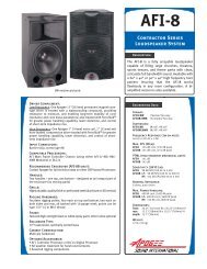
Amplifier Back PanelLine AC Panel of an <strong>Apogee</strong> <strong>APL</strong> <strong>Subwoofer</strong>1 2 3 4 51 Power Switch2 Main AC Protection Fuse3 AC Input Connector, Neutrik Powercon NAC3FCA4 AC Line Voltage Selection Switch5 AC Output Connection, Neutrik Powercon NAC3FCB29
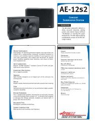
23467Audio Input Panel of an <strong>Apogee</strong> <strong>APL</strong> <strong>Subwoofer</strong>11 Signal Presence Indicator52 System Protection Indicator3 Amplifier Clip Indicator84 System Power Indicator5 Volume Control96 Ch 2 Mute Switch7 Ch 1 Mute Switch8 Balanced Line Audio Input, XLR9 Balanced Line Audio Loop-through, XLR30
SpecificationsEnclosure Type<strong>APL</strong>-1020° Trapezoidal,optimally-vented bass<strong>APL</strong>-12Rectangular,optimally-vented bassFormatSelf-contained dual power amplifiers with integrated processing electronicsFrequency Response 34 Hz to 100 Hz ± 3 dB (on axis) 32 Hz to 100 Hz ± 3 dB (on axis)DispersionOmni-directionalMax. SPL 131 dB cont./ 137 dB peak (@1m) 134 dB cont./ 140 dB peak (@1m)Dimensions32" W X 22.5" H X 24" D(813 X 572 X 610mm)44.75" W X 30" H X 22.5" D(1137 X 762 X 572mm)Drivers Dual <strong>Apogee</strong> 15" with Ferrofluid ® Dual <strong>Apogee</strong> 18" with Ferrofluid ®InputAmplifier Output PowerRMS LimiterPeak LimiterXLR, active balanced 35k ohms, with loop-through output connector2400W total music power, dual amplifiers100ms integration time, long duration protection,VIProtect3 to 5ms fast-acting transient protection,VIProtectProduct Weight 145 lb. (65.8 kg) 214 lb. (97 kg)AC Voltage115V AC or 230V AC selection switch on back panel;Neutrik Powercon connector with loop-through31
Line Drawings<strong>APL</strong>-10 SELF-POWERED SUBWOOFER32
<strong>APL</strong>-12 SELF-POWERED SUBWOOFER33
LIMITED WARRANTY;EXCLUSION OF CERTAIN DAMAGES<strong>Apogee</strong> <strong>Sound</strong> International's self-amplified speaker products are warranted to be free from defects inmaterials and workmanship, under normal use and service, when installed and operated in accordancewith product specifications, from the date of original purchase for a period of three (3) years.If any part of the equipment covered by this warranty malfunctions, it will be repaired or replaced, at ouroption, provided the equipment is shipped prepaid to an authorized <strong>Apogee</strong> Service Facility.This warranty does not extend to finish; appearance items; or any product malfunctions due to abuse,accident, misuse, negligence, misapplication or operation under other than specified conditions, or ifaltered in any way; nor does it extend to incidental or consequential damages of any kind.THIS LIMITED WARRANTY IS OUR SOLE AND EXCLUSIVE WARRANTY AND THEPURCHASER'S SOLE AND EXCLUSIVE REMEDY. APOGEE SOUND INTERNATIONALMAKES NO OTHER WARRANTIES OF ANY KIND, EXPRESS OR IMPLIED, AND ALLIMPLIED WARRANTIES OF MERCHANTABILITY AND FITNESS FOR A PARTICULARPURPOSE ARE HEREBY DISCLAIMED AND EXCLUDED.Before returning products for warranty or non-warranty repair or replacement, call the CustomerService Department to obtain a factory-issued Return Merchandise Authorization (RMA) number, andmake sure the freight charges are prepaid. Merchandise returned without an RMA on the outside of thebox will not be accepted.<strong>Apogee</strong> <strong>Sound</strong> InternationalCustomer Service Department50 Spring StreetRamsey NJ 07446, USATel: 800-999-2809Fax: 800-999-9016The salespersons or agents of <strong>Apogee</strong> <strong>Sound</strong> International, or its dealers, are not authorized to make anyrepresentations, promises, or warranties regarding products on behalf of <strong>Apogee</strong> <strong>Sound</strong> International orin any manner obligate <strong>Apogee</strong> <strong>Sound</strong> International to the purchaser.This warranty applies only to products sold in the United States. Please consult your <strong>Apogee</strong> <strong>Sound</strong>International distributor for warranty information, service, and parts outside of the United States.35
50 Spring Street, Ramsey, NJ 07446, USATel. 201-934-8500, Fax: 201-934-9832www.apogeesound.com