tufftrack® grassroad pavers - NDS
tufftrack® grassroad pavers - NDS
tufftrack® grassroad pavers - NDS

Create successful ePaper yourself
Turn your PDF publications into a flip-book with our unique Google optimized e-Paper software.
TECHNICAL SPECIFICATION GUIDETUFFTRACK ® GRASSROAD PAVERS ®This information is relevant only to the product(s) identified within this document and is not intended for use with any otherproducts. Please consult <strong>NDS</strong> Technical Services at (888) 825-4716 or e-mail TechService@<strong>NDS</strong>pro.com if you have anyquestions pertaining to specifications, installations, or recommended applications that are beyond the scope of this document.BEFORE BEGINNING ANY PROJECT, CONSULT A CURRENT EDITION OF THESE SPECS AT: WWW.<strong>NDS</strong>PRO.COM
TECHNICAL SPECIFICATION GUIDETUFFTRACK ® GRASSROAD PAVERS ®TUFFTRACK ® Grassroad Pavers ® is a load-bearing paving system.TUFFTRACK ® Grassroad Pavers ® is designed to be placed directly over a lightly compacted plantingbase which is installed on a Class II compacted gravel road base. Proper installation will prevent soilcompaction that damages the root system of the grass. TUFFTRACK ® can also be used for light dutyapplications without the road base by simply compacting the planting base as per the manufacturer’sdetailed installation instructions and drawings, along with a local engineer compaction recommendation.Recommended Uses:Light to moderate traffic loads, including:• Golf Cart Paths• Residential Driveways• Service Roads• Parking Lots• Trail Reinforcement• Overflow Parking Area• Bike Paths• RV and Boat Parking• Roadway Shoulders• Wheelchair access paths• Truck & cart wash-down areas• Outdoor shower runoff areas• Outdoor drinking fountain runoff areasHeavy Traffic Loads, including:• Fire lanes• Emergency vehicle access roads• Service vehicle utility roads• Truck maintenance and equipment yards• Construction entrance soil stabilizationNon-Recommended Uses:• Not recommended for traffic on slopes exceeding a 10% grade (staking may be required.).• Not recommended for the playing surface of any sports field (e.g. baseball diamonds,football fields, etc.).• Not recommended to support tread driven military vehicles.• Not recommended for light or heavy-duty tread driven construction equipment or bobcatstyle tractors.• Other non-recommended uses exist, consult <strong>NDS</strong> Technical Services for details.Paver Turf Maintenance Tips And Techniques1. Do not use aeration equipment over turf areas containing grass <strong>pavers</strong>.2. Do not use scalping equipment over turf areas containing grass <strong>pavers</strong>.3. Do not use de-thatching equipment over turf areas containing grass <strong>pavers</strong>.4. Turf care and mowing practices that minimize the need for de-thatching should beadopted. These may include:• Planting turf varieties that are resistant to thatch build-up (like tall fescues) providedthe selected variety is appropriate for the site’s growing conditions.• Collecting grass clippings when mowing.• Using slow-release fertilizers.• Adopting deep watering irrigation techniques.5. When snow clearing equipment is used, skid shoes must be used or the snow plow mustbe raised a minimum 2” above the paver surface. This will prevent the plow from digginginto the sod area and keep from breaking the paver mat.
TUFFTRACK ® GRASSROAD PAVERS ®Installation GuidelinesPre-Installation1. Order approximately 5% additional product over the total square footage required for a project to offset forcurves and possible installation errors.2. Check with local permitting or fire authority as to any requirements for “during installation” inspectionsbefore the installation of the base course in any area that may provide emergency vehicle access.3. Back filled and reclaimed areas may require compaction and testing before the installation of the base course.4. Define the boundary of the proposed grid work using a string line, header board, concrete curb or otherhardscape border as specified by the landscape architect or engineer.5. The installation of TUFFTRACK ® Grassroad Pavers ® should occur after the completion of any nearbycurbs, sidewalks, asphalt, sprinkler systems, or other hardscape.Site Selection1. Install with no more than a 6% grade for emergency access lanes or for heavy vehicle access.2. Install with no more than 10% grade when used for light vehicular traffic. Anchoring pins must be installedin this application in a manner specified by a qualified architect or soils engineer.i. “U” shaped staples are not recommended. This includes 11 gauge 6” x 1” x 6” or 9 gauge8” x 1” x 8” staples normally used to secure jute and blanket erosion control products, asopposed to grass <strong>pavers</strong>.ii. Geotextile pins or nails are recommended. Industry practices suggest 6” nails with 1.5”washers for hard or rocky soils. For sandy soils, 12” or 18” geotextile pins with 1.5” washersmay be used. Consult a qualified architect or soils engineer for the proper method of anchoringthe TUFFTRACK ® application specific to your project. Note: air gun installation devices usedfor driving geotextile pins should not be used in a manner that damages the TUFFTRACK ®Grassroad Pavers ® .iii. Anchoring frequency and patterns are determined by steepness of slopes and channel beds (e.g.determining how many anchoring pins are needed per square yard). Consult a qualifiedarchitect or soils engineer for the proper method of anchoring the TUFFTRACK ® applicationspecific to your project.3. Installations over 10% grades are not recommended for TUFFTRACK ® Grassroad Pavers ® .Installation1. The installation of TUFFTRACK ® Grassroad Pavers ® is generally done at the same time as other grassinstallation on the site, and after the completion of major area construction.2. Ensure that the paver is installed right-side-up. Warranties are voided for <strong>pavers</strong> installed upside-down.3. Lay the first section of TUFFTRACK ® Grassroad Pavers ® either where there is an available straight border,or where there is the longest available single run.4. Continue to lay additional panels of TUFFTRACK ® Grassroad Pavers ® to cover the entire area, securelyconnecting the Tongue & Groove latching system to create an integral paver mat.5. Stagger the joint lines (between adjoining panels) among neighboring rows of installed TUFFTRACK ®Grassroad Pavers ® for an even stronger mat.6. Be sure to leave the recommended 1 inch minimum clearance between the paver mat and any (preinstalled)fixed objects or surface structures such as utility poles, valve boxes, sprinkler heads, drainage grates,curbs, walls, poured concrete, etc.7. The paver can be trimmed/cut to fit any fixed objects or surface structure using a hand saw, PVC pipecutter, utility cutter, or appropriate power saw may also be used if desired. Be sure to follow allmanufacturers operating and safety instructions when using such tools.TECHNICAL SPECIFICATION GUIDE
TECHNICAL SPECIFICATION GUIDETUFFTRACK ® GRASSROAD PAVERS ®Planting1. TUFFTRACK ® Grassroad Pavers ® should be filled with soil and planted within 30 days ofbeing installed.2. A sandy loam or loam soil should be used to fill the empty grass paver cells. The selection ofsandy loam or loam soil should be made based upon the soil requirements of the turf varietyselected for the project. Sand is not a suitable fill material for TUFFTRACK ® GrassroadPavers ® .3. Select a turf variety well suited to the anticipated traffic frequency and local heat and growingconditions.i. For example, faster growing varieties are preferred for light traffic applications(quickly regenerates blades bent by traffic). Perennial rye grass and tall fescuesmay be preferred over slower growing blue grass turf varieties.ii. Resistance to thatch build-up, drought and disease resistance should be consideredtoo.4. Seeded or sodded areas should be protected from non-emergency traffic for 4 to 6 weeks oruntil the grass is sufficiently established to handle traffic.5. Seed vs. Sod planting should be determined based upon the anticipated frequency of traffic,noting that:i. Seeding or hydroseeding is recommended for light to moderate traffic applications.• Seeded grass <strong>pavers</strong> should be filled with soil 1/4” below the cell walls (protectsthe crown of mature grass below the top of the cell wall, the top of the cellwall takes the weight of traffic).• Broom the soil into the paver, lightly water and allow soil to settle overnightbefore seeding (soil should settle about 1/4” below top of cell walls).ii. Sodding is recommended for emergency traffic applications.• Sodded <strong>pavers</strong> should be filled with soil to the top of the cell walls.• Broom the soil into the paver, lightly water and allow soil to settle overnight(soil should settle about 1/4” below top of cell walls). Broom a second layer ofsoil flush with the top of the cell wall before laying sod.6. Grass paved areas must have irrigation systems sufficient to maintain year-round healthy turf.7. When planting trees nearby a TUFFTRACK ® Grassroad Pavers ® surface, it is advisable toinstall a root barrier product around the root ball to prevent shallow roots from interferingwith surface integrity or the road base. <strong>NDS</strong> root barrier products are recommended.8. When a path of TUFFTRACK ® Grassroad Pavers ® is installed bisecting a large lawn or grassfield to provide a service road, it is recommended to plant shrubs or trees to mark the ends`nd edges of the grass paved strip. This guides service vehicle drivers to stay on the grasspaved strip whenever they have to traverse the large lawn or grass field.
Product SpecificationsSpecifyMaterialRecyclabilityPaver SizePaver Wall ThicknessPaver DescriptionPaver Top SurfaceAssembly MechanismBottom Open AreaUnique Product FeaturesPaver ColorCompressive StrengthNominal Coverage AreaChemical ResistanceWeight Per UnitTUFFTRACK ® GRASSROAD PAVERS ®TUFFTRACK ® Grassroad Pavers ® is an injection-molded, nested honeycomb,plastic panel grass paver structure. Designed for natural grass pavedenvironments.TUFFTRACK ® <strong>pavers</strong> are manufactured from up to 100% recycledPolyolefin plastic.TUFFTRACK ® <strong>pavers</strong> are 100% recyclable. Please recycle whenever possible.24” x 24” by 1 1/2” in height per panel. Each paver approximates a 2’ by 2’ flatprofile, square structure when assembled to another TUFFTRACK ® paver.All internal and external walls, the bottom surface and the tongue latches areinjection-molded to a uniform thickness of 12 hundredths of an inch (0.12).Each paver shall contain (120) 2 1/2” hexagon cells, in a nested honeycombform. The bottom of each cell shall contain a 1 1/4” diameter holein the center and a series of (6) 0.475” x 0.212” perimeter openings(through the bottom of the paver); one opening at the bottom of each cellwall to discourage root girdling within the cell. The bottom surface of thepaver shall be flat and void of vertical post or obstructions.The top surface of the hexagonal cell walls of the TUFFTRACK ® paver is(smooth), and void of notches or grooves.Each paver shall have a Tongue & Groove latching system molded aroundthe perimeter of the paver structure. The Tongues measures 1” x 1” by0.12 in thickness and the groove (receiver opening) measures 1” by 12hundredths of an inch (0.12).TUFFTRACK ® paver structure has over 41% open area across the entirebottom surface, a total area equal to over 228 square inches per paver.The series of (6) 0.475” x 0.212” perimeter openings at the bottom of eachcell wall serves as an “anti-girdling device” to discourage grass roots fromcircling inside the cell structure. The slot openings represent 56% greaterwater and oxygen exchange through the paver bottom over competitors.These features are unique to the TUFFTRACK ® only.The color of the paver is black and contains carbon black for ultravioletstabilization.The compressive strength of the TUFFTRACK ® is 98,770 lbs. (psf)“empty” (unfilled cells) which is equal to 685 lbs. (psi). United StatesTesting Company, Inc. #720148-2.When assembled each paver approximates a 4-foot square surface area ofcoverage.The product has superior chemical resistance and is totally inert.4.5 pounds per (1) 24” x 24” paver structure.TECHNICAL SPECIFICATION GUIDE
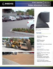
TECHNICAL SPECIFICATION GUIDETUFFTRACK ® GRASSROAD PAVERS ®Product FeaturesTUFFTRACK ® Grassroad Pavers ® have features found in no other grass paver product in the industry. Theunique slot opening (though the bottom surface of the paver) at the base of each hexagonal cell wall is a one-ofa-kindfeature. In addition to promoting a greater flow of water, oxygen and nutrients through the paver, the slotopenings promote grass root penetration into the soil below. Additionally the open slot design prevents rootsfrom circling (girdling) inside the bottom of the hexagon cells (circling roots can diminish healthy grass establishmentand stunt future growth). The anti-girdling effect of the slot openings can make the difference betweensuccess or failure of your project. In floodplain areas where drainage is critical, TUFFTRACK ® GrassroadPavers ® excel in water runoff capabilities by an additional 56% drainage capacity over any other paver in thehoneycomb class.The Tongue & Groove (T&G) latching system is another unique feature found only on this product. The heavydutytongue latches molded strategically around the perimeter of each paver measure 1 inch by 1 inch by 12hundredths of an inch (0.12) in thickness. The advantage of the heavy-duty latching system, in addition to theincreased wall support against sheer stresses, is the extended longevity of the grid work system as the grassmatures and the ground settles. The T&G latching system enables rapid assembly of the product, locking onepaver to another in the process and reduces labor costs.0.475” x 0.212” slot opening commonto all cellsTUFFTRACK ® Grassroad Pavers ® sectionTop ViewNot to scale1 1/4” diameter cell openingcommon to all cellsUniform wall thickness0.12 hundredth of an inch1” x 1” x 0.12T & G tongue latchThe unique design of the bottom surface of the TUFFTRACK ® Grassroad Pavers ® , with hundreds ofopenings/edges acting as a superior gripping mechanism, promotes lateral stabilization of the grid workingwithin the soil environment.“From an Arboricultural standpoint, the greater the ratio of cell openings to the surface of the soil, thegreater the opportunity for natural, healthier grass root penetration and water & oxygen movement.”
Paver DesignTUFFTRACK ® GRASSROAD PAVERS ®TUFFTRACK ® Grassroad Pavers ® are configured in a nested honeycomb format utilizing hexagonal cells to form a4 square foot flat block structure measuring 24” by 24” by 1 1/2” depth, (approximate dimensions.) The paver designutilizes a full rigid base to prevent the paver from being pressed into the sub-base. In addition to the 1 1/4” hole typicallyfound in the cells of nested honeycomb <strong>pavers</strong>, the TUFFTRACK ® paver has a series of 1/4” x 1/2” slot openingsthrough the bottom at each cell wall, thus increasing the movement of water, oxygen, nutrients and root growththrough the paver bottom by an additional 56% over any other paver in its class.Design aspects address overall mat strength, fatigue and durability factors. These aspects are addressed through threemain design areas: paver design, material composition and molding technique.Design TheoryTUFFTRACK ® Grassroad Pavers ® are engineered to withstand several types of forces that are capable of beingapplied in traffic situations, as well as pedestrian traffic applications.• Major forces that are applied during traffic include lateral pressure from turning, braking and acceleration. Thesetorsional forces must be addressed in two key areas. They are paver mat movement and paver separation. TUFF-TRACK ® design incorporates two unique features that address these issues. The first is the heavy-duty T&G“tongue & groove” latching system. Each tongue measures 1” by 1” by 0.12” in thickness. There are 26 in all strategicallypositioned around the perimeter of each paver block. When assembled to another paver, the walls and T&Glatching system enhances the integrity of the wall structure to provide superior strength. The insertion depth of eachtongue into the receiver slot of the other block is 1 inch: This provides a greater assurance against paver separation.The six ground slot openings in each of the 120 cells, coupled with the 1 1/4” center hole through the cell bottomprovides for exceptional gripping power into the sub-surface soil, thus preventing lateral paver mat movement.• Nesting integrity is critical, unlike a simple overlapping connection, or post and eye connection, the heavy dutyT&G latching system does not allow the paver units to be pulled apart (on the flat plane). The paver latching systemsecurely fastens the entire mat into one continuous section. This becomes extremely important in two types of situations.The first is obvious — traffic load movement. The second, not so obvious condition can occur as the projectages. Subtle changes in ground conditions could easily result in paver displacement or separation (mat failure), aswould be the case with inferior locking mechanisms found in other paver products.TECHNICAL SPECIFICATION GUIDE• In any consideration of product durability involving heavy traffic or compression “impact” loads, the ultimate testedand documented load rating of the product must be considered. TUFFTRACK ® has been tested for compressivestrength at 98,770 pounds per square foot (bare product), with an ultimate stress load capacity of 128,400 lbs persquare foot (mature site). In working terms that means the capability to support a vehicle weighing in excess of 90tons (or) 180,000 lbs gross vehicle load! The T&G latching system is differentiated from other types of paver connectionsin that the joints will actually become stronger as more pressure is applied. When connected it is nearlyimpossible to separate the TUFFTRACK ® paver units without raising the paver to a 30 degree angle, thus providinga secure paver locking mechanism. As the grass matures, the TUFFTRACK ® produces an astounding sub-structurecapable of handling the heaviest loads imaginable.• In addition to securing the paver mat into one solid, contiguous area, the heavy duty T&G latching system distributesthe downward vertical forces over the entire paver mat grid work. This allows point loads to be carried by multipleadjoining <strong>pavers</strong>. While this effectively prevents single incident failures, it also works to prevent accumulativeload failures over time. The T&G latching system in conjunction with the full base design, work together in preventingthe compaction of the paver mat into the sub-base, and eventual failure of the porous paved area.
TECHNICAL SPECIFICATION GUIDETUFFTRACK ® GRASSROAD PAVERS ®• In the area of “friendly” pedestrian traffic design the TUFFTRACK ® has eliminated the out-dated slots found onthe top surface of most nested honeycomb type <strong>pavers</strong> thus providing for enhanced pedestrian safety when appliedin pedestrian areas such as overflow parking, driveways, general pedestrian walkways, and RV parking areas.Material CompositionTUFFTRACK ® Grassroad Pavers ® material must be made from up to 100% recycled Polyolefin plastic. Thenature of Polyolefin plastic is rugged, flexible and ideally suited for outside exposure and longevity. Plasticpolymers can show a decline in mechanical properties during service lifetime when they are exposed to sunlight.At <strong>NDS</strong>, we use UV inhibitors within our plastics in order to prevent a breakdown in the strength ofour <strong>pavers</strong> over time due to environmental effects.TUFFTRACK ® Grassroad Pavers ® are manufactured in the color black to utilize carbon black polymers totheir fullest extent in providing the highest quality of ultra violet protection for the paver product. It is wellknown that in the general application of grass <strong>pavers</strong>, the final grid work of <strong>pavers</strong> in covered with grass, as isthe typical application of a fire access road. The top edge of the paver may be visible in a new vehicular trafficaccess installation; however, the natural green grass look is apparent at a slight angle from the perpendicular. Ifyou are considering a large project utilizing the TUFFTRACK ® Grassroad Pavers ® and the paver color representsa significant factor in your decision-making process, please contact <strong>NDS</strong> or your manufacturer’s representativeto discuss your project.As good corporate custodians of our environment, <strong>NDS</strong> uses quality reprocessed recycled materials in the manufactureof TUFFTRACK ® Grassroad Pavers ® . With the growing in the use of recycled materials, TUFF-TRACK ® should qualify for all projects requiring recycled construction materials.Molding TechniqueTUFFTRACK ® Grassroad Pavers ® are proudly manufactured in the U.S.A. in our own facility in Lindsay,California. The <strong>pavers</strong> are injection-molded with computerized machines, which means that they are manufacturedto very exacting specifications. The <strong>pavers</strong> are molded to an exact temperature range that will not damagethe molecular chain of the polymer. The use of a high-quality reprocessed recycled resins and UV inhibitors coupledwith computerized manufacturing technologies guarantees the TUFFTRACK ® Grassroad Pavers ® willpreserve their strength over time.Compression TestsCompression tests are used to determine the yield and ultimate load strength of a given paver. The UnitedStates Testing Company, Inc. performed the stress load testing on the TUFFTRACK ® Grassroad Pavers ®using the following procedure: each sample paver was individually placed flat on the fixed plate of an Instronmachine. A load was then applied to the top surface of the paver, through a 5-inch by 5-inch steel plate, at arate of crosshead motion of 0.5 inch per minute until failure. The test was performed at two locations oneach sample. The compressive strength of the specimen was then determined by dividing the maximum loadinto the area through which the load was applied. The ultimate compressive strength of the TUFFTRACK ®grass paver product was 98,770 pounds per square foot (see testing and documentation data in the TUFF-TRACK ® Grassroad Pavers ® brochure.)Drive-on TestsThe drive-on tests are the true test of how the paver will perform under vehicle load. The <strong>pavers</strong> areinstalled and turf is established, then a test vehicle (usually a fire truck) is maneuvered on the installed<strong>pavers</strong>. The <strong>pavers</strong> must not show any signs of movement. The <strong>pavers</strong> must not raise or tilt up in any way(often the case with flexible <strong>pavers</strong> and large concrete block systems), the driving surface must not interfere
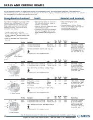
TUFFTRACK ® GRASSROAD PAVERS ®with the ability of the vehicle to maneuver anywhere on the grass paved area. Many fire departments willsaturate the area with water, which ensures a true test of how the <strong>pavers</strong> will perform in an actual emergencysituation. Tests vary depending on the final application (fire land, parking, utility access etc.). Pleasecontact the manufacture or manufacturer’s representative for additional support data.PermeabilityRunoffIn comparing concrete or asphalt storm management with the use of TUFFTRACK ® Grassroad Pavers ®there are several factors to consider. In general, TUFFTRACK ® grass paver provides a lower runoff coefficient,a prolonged time of concentration, a much higher rate of percolation and a cleaner runoff.As a general rule, using TUFFTRACK ® grass paver over a rock and sand base with a sandy loam site soil(CN30) will promote a situation unlikely to generate surfacerunoff in an average rainstorm. We define an averagestorm as one delivering less than six inches of rain in atwenty-four hour period.When TUFFTRACK ® grass paver is installed over claysoils (CN78), the performance will vary slightly dependingupon the depth of the base course because of internalwater storage capacity less antecedent moisture present.TUFFTRACK ® grass paver provides a permeable area ofapproximately 61% per square foot of surface area.As per Technical Release #55, US Dept of Agriculture,Soil and Conservation Service, the evaluation of stormwater management objective is done by the followingmethod. Calculate the existing (pre-construction) runoffvolumes and time of concentration factors. Next calculatearea and runoff volumes, which will be generated by newhard surface areas. Runoff reduction can be calculated andcompared when using Table 1 which lists runoffpercentages from various soils based on “meadow” typecover and a 24-hour rainfall.Runoff % - 24 Hr RainfallSand to Clay SoilsInches CN30 CN58 CN71 CN781.0 0.0 0.0 0.01 0.061.2 0.0 0.0 0.03 0.101.4 0.0 0.0 0.05 0.141.6 0.0 0.0 0.08 0.181.8 0.0 0.01 0.11 0.212.0 0.0 0.02 0.13 0.242.5 0.0 0.05 0.20 0.323.0 0.0 0.09 0.25 0.384.0 0.0 0.17 0.35 0.475.0 0.0 0.23 0.42 0.546.0 0.01 0.29 0.48 0.607.0 0.03 0.34 0.53 0.648.0 0.05 0.39 0.57 0.679.0 0.08 0.43 0.61 0.7010.0 0.10 0.46 0.64 0.7311.0 0.12 0.49 0.66 0.7512.0 0.15 0.52 0.68 0.76Table 1: Technical Release #55, US Dept of Agriculture,Soil and Conservation Service tableFrequent Traffic & Parking ConsiderationsCommonly we are asked about using TUFFTRACK ® Grassroad Pavers ® as an overflow parking or drivewaysituation. This is how we typically address the requirements for a satisfactory installation.The root systems ofindigenous turf are protected within the cellular walls of the paver. Frequent vehicular traffic does not harm thegrass root structure because of the cellular wall protection, however blades of grass will be cut off if driven ondaily. If someone parks over the same spot everyday, the grass simply cannot survive. Turf requires light, andthat requirement cannot be met unless parking areas are used less than daily or are rotated. We cannot specifythe rotation you will require. This is determined by your climate, turf and other factors. Most likely it is somethingthat will require a certain amount of testing and client feedback.TECHNICAL SPECIFICATION GUIDE
TECHNICAL SPECIFICATION GUIDETUFFTRACK ® GRASSROAD PAVERS ®Root PenetrationThe primary source of water and nutrients will not be above the road base. As an example the roots offescue can penetrate to a depth of over 20 feet (6m). The entire base and paver structure is not designed toretain water — in fact its primary purpose is to allow the water to percolate into the soil quickly, whileretaining strength. While the soil in the paver structure is important and is a source for nutrients andmoisture, is it not the primary source.As a general reference on base preparation, the main purpose of the base is to obtain 95% compaction whilestill allowing the water to percolate through the entire paved area. The type of stone used for the base willusually have no bearing on growth, except in one instance. Some areas of the country use gravel which isheavy in lime (limestone based) and can slow root growth. Generally speaking you should use good, clean3/4” (1.9cm) gravel which is free from any agents which would slow turf growth.A General Statement of FactA grass paving structure such as TUFFTRACK ® Grassroad Pavers ® or any other grass paving structure forthat matter, whether it is constructed of plastic or concrete, is only as good as the base foundation uponwhich it is installed. This is the primary factor that must be considered beyond design or desire.Paver Installation GuidelinesArchitectural and Engineering “Base” DeterminationThe first decision in your project planning must address the correct “base construction” that will support theproposed traffic load weight anticipated on your site. i.e. fire lane, overflow parking, light utility access road,etc. There are three base options from which to choose:Option AOption BLight Load/High Traffic – Base shall be prepared using a 3” course aggregatebase (CA-7) & 1” fine aggregate (FA-1)Fire Lane/Heavy Load – Base shall be prepared using a 6” course aggregatebase (CA-7) & 1” fine aggregate (FA-1)Option CLocal Municipal Codes – Base shall be installed according to the localspecifying authority or municipal codesIn general terms the Fire Land/Heavy Load base is composed of two components (1) the sub-base, constructed as aClass II road base, 6 inches of course aggregate mix brought to a 95% compaction, (2) the planting base, of 1 1/2”to 2” Depth of prescribed planting soil mix leveled and firmly rolled. The planting base is the actual paver base.
Site PreparationABCPaver Assembly & InstallationABCDTUFFTRACK ® GRASSROAD PAVERS ®Remove all foreign top grade structures and excavate existing site soil to accommodate the basespecified for your traffic/load requirements. (see typical section, page 12).Install the sub-base, per architectural and/or engineering drawings and written specifications describingthe depth, load rating, construction materials and required compaction.Add the planting basesoil required per site soil conditions, as specified by the landscape architect orengineer, fine grade the planting base soil and apply roller pressure to establish moderate compaction.Position pallets of <strong>pavers</strong> strategically to their distribution needs and begin the assembly of <strong>pavers</strong> inthe initial run (longest straight run) lay down the first row of assembled <strong>pavers</strong> against the string lineor header, then connect the next assembled row of <strong>pavers</strong> to the first row and so on until assembly iscompleted. (See paver assembly guide, page 14).In the assembly process described above you must cut clearance openings through individual <strong>pavers</strong>as required to assure that all (pre-installed) surface structures such as valve boxes, drainage grates, utilitypoles, sprinkler heads etc. are correctly positioned within the paver grid work at the appropriatelevel to finished grade.Upon completion of the assembled paver grid work it is important to re-examine all paver fittingsaround surface utilities and bordering structures to assure proper (1” clearance). Make all adjustmentsor replacements prior to soil fill or planting.If you are installing a fire lane / heavy load access that requires a top sod planting, fill the grid workwith the prescribed planting soil mix and back rake the entire surface to level the soil to the top edgeof the paver grid work and water moderately to promote soil setting. (See options below)Planting – Sod, Seed or HydroseedingNote: There are generally three methods of plantings to consider. These are described below.For soil planting elevations (See Planting Profile/Soil Level, page 15)1. Top Dressing with Sod — (typical fire lane application): Sod is laid on top of the paver grid work after ithas been filled with soil, back raked to top of cell walls and watered moderately. Note: Within a fewhours after water is applied, the soil within the cells will settle down into the cells about 1/4”. Thesurface is now ready for the final top dressing of soil (If deemed necessary) and then the sod laid in astaggered pattern on top of the planting surface. Water the sod and set a watering schedule.2. Recessed Sod Planting — (Typical high use traffic application): In this treatment you must order 3/4” or1” sod. Do not add soil to paver grid work. Lay sod in a staggered pattern on the paver grid work,water sod (saturate) to prepare for compression into paver cells. Use a hand water roller or powerdriven roller to compress the sod and root system completely into the cells. When using a rolleralways follow the Manufacturer’s Operation, Maintenance and Safety instructions. Note: If you areunable to obtain a 3/4 to 1” sod you must use a thinner cut sod. When using a thinner sod you willneed to add planting soil into the cells prior to laying the sod: i.e. with 1/2 inch thick sod add 1/2inch of planting soil into cells. Apply sod as described above, water and set a watering schedule.3 Seeding or Hydroseeding– (typical high traffic application): Fill the entire paver grid work with planting soil,back rake soil to top of cell walls and water generously. Note: Within a few hours after water is applied, thesoil within the cells will settle downward into the cells about 3/8 of an inch. Broadcast fertilizer and seedor hydroseed over the paver grid work. Water the new planting and set a watering schedule.TECHNICAL SPECIFICATION GUIDEDifferent soil textures and planting mixtures will settle at different depths into the cell walls when watered initially. In theevent of excessive soil settling, additional soil must be added to adjust the final planting level within the cells.
TECHNICAL SPECIFICATION GUIDETUFFTRACK ® GRASSROAD PAVERS ®Paver Assembly Tips & TechniquesFive Simple Steps to AssemblyGenerally speaking the fastest assembly technique is to pre-assemble longindividual rows of TUFFTRACK ® Grassroad Pavers ® along a major lateralof the proposed grid work. Continue joining the <strong>pavers</strong>, row after rowuntil the grid work is completed. It sounds easy to assemble because it reallyis easy, using the right techniques described below.Step 1. Define the boundary of the proposed grid work, using a string line,header board, concrete border or other devices as specified by the landscapearchitect or engineer. If you are installing a fire lane, for example, youmay be required to pour 10” by 10” concrete “visual boarder” strips onmajor laterals. If there is no boarder required you can stake a 2” x 4” alongthe initial row of <strong>pavers</strong> to give you a good back up support edge andstraight line to begin with.Step 2. Assemble the first row of <strong>pavers</strong> along the established lateral nestingthe hexagonal cells as illustrated in (A) and (step 1.A). Snug the assembledrow of <strong>pavers</strong> up against the boarder or header with 1 inch spacers.The tongue and groove latching system on the paver will only fit one sideof the other paver, eliminating misconnections & speeding up assembly.Step 3. Assemble the second row of <strong>pavers</strong>, laying the row in close proximityto the first row nesting the hexagonal cells, as illustrated in (B). Whencompleted, move the second row into a nesting position with the first row.(See Step 1.B below) and join them together, lifting eachside slightly as illustrated in (C).Step 4. Continue the assembly as described in Step 3(above) until the major grid work is completed. In thisprocess you must cut clearance openings through individual<strong>pavers</strong> as required to assure that all pre-installed surfacestructures such as valve boxes, drainage grates, utility poles,sprinkler heads etc. are correctly positioned within thepaver grid work at the appropriate level to finished grade.Step 5. If the grid work has an irregular shape, cut the<strong>pavers</strong> with a skill saw, saber saw or hand saw to conformto the regular shape. The finished cuts should be made to a1” tolerance. See Illustration 1.Notes: 1. Allow 3 to 5 percent additional product to thetotal required to offset for cuts, curves and mistakes.2. The TUFFTRACK ® grass <strong>pavers</strong> can be assembledand nested “off center” to fit irregular shapes &reduce waste. Illustration 1
TUFFTRACK ® GRASSROAD PAVERS ®Planting Profile/Soil LevelsWhen using plastic grass <strong>pavers</strong> in a professional landscape applications involving fire lanes, utility roads, andoverflow parking there are several textures of grasses and planting methods that can be achieved, howeverthere are only two planting profiles that address the soil elevation adjustment to final grade and ultimatelydetermine the finished surface you can achieve. They are Top Profile Plantings which can include laying sod,seeding, or hydroseeding, and Recessed Plantings which also include laying sod, seeding or hydroseeding. Theprimary difference in the two planting profiles is the planting soil elevation or finished grade in relationship tothe top surface of the grass paving grid work.Top Profile PlantingSod or grass is grown on top of the grass paver grid work after assembly of the product is completed and thegrid work has been filled, watered and “re-filled” with the prescribed planting soil mix. This is by far the mostcommon application used in the construction of fire lanes integrated within building structures. In this applicationthe surface of the grass has all the appearance of a natural landscape green environment within the surroundinglandscape. The actual access to the fire lane, as well as turns and perimeters of the fire lane, must bemarked with shrubs, boarders, gates or other fire warning devices or signage, as prescribed by the governingfire authority or municipal code. The Top Profile Planting method, using sod laid on top has an advantage overseeding or hydroseeding because the sod totally covers the surface of the paver grid work immediately andthus reduces pedestrian tripping and potential liability. Additionally the paver grid work is protected from thedamaging ultra violet rays of the sun. This is the most economical and the easiest planting application toinstall. See detail A below.Recessed PlantingThis planting method is used in both fire lanes and most other application where vehicular traffic, vehicularstorage and other temporary parking/traffic are anticipated. The concept here is to achieve an ultimategrass/soil level recessed about 1/4 to 1/2 inch down inside the grass paver cell. When the grass/soil level isrecessed within the cells it is possible to drive vehicles over the surface (on the top of the cell walls) withoutinflicting serious damage to the grass blades or compacting the soil within the individual cells. The radius ofthe tire, traveling across the surface does not extend down inside the hexagonal cell walls of the grass paver toa depth that would compact the soil or damage the grass. See detail B and C below.Whether you are going to use the Top Profile Planting or the Recessed Planting method you must considerappropriate horticultural practices associated with the planting soils, mixes, amendments and treatments withinthe soil planting zones illustrated below. In adverse soil conditions consult a horticulturist or soils specialist.Planting Profile/Soil LevelsTECHNICAL SPECIFICATION GUIDETop Profile PlantingRecessed Planting
TECHNICAL SPECIFICATION GUIDETUFFTRACK ® GRASSROAD PAVERS ®Section Drawings
Soil DefinitionsSandy loamTUFFTRACK ® GRASSROAD PAVERS ®Soil material that contains either 20% or less clay, with a percentage of silt plus twice the percentage of clay thatexceeds 30, and 52% or more sand; or less than 7% clay, less than 50% silt, and between 43% and 52% sand.Loamy SandCoarse sandy loam25% or more very coarse and coarse sand and less than 50% any other one grade of sand.Sandy loam30% or more very coarse, coarse, and medium sand, but less than 25% very coarse sand, andless than 30% very fine or fine sand.Fine sandy loam30% or more fine sand and less than 30% very fine sand or between 15 and 30% very coarse,coarse, and medium sand.Soil material that contains at the upper limit 85% sand, and the percentage of silt plus 1.5 times the percentage ofclay is not less than 15, at the lower limit it contains not less than 70 to 85% sand, and the percentage of silt plustwice the percentage of clay does not exceed 30.SandLoamy coarse sand25% or more very coarse and coarse sand and less than 50% any other one grade of sand.Loamy sand25% or more very coarse, coarse, and medium sand and less than 50% fine or very fine sand.Loamy fine sand50% or more fine sand or less than 25% very coarse, coarse, and medium sand and less than50% very fine sand.TECHNICAL SPECIFICATION GUIDESoil material that contains 85% or more sand; the percentage of silt plus 1.5 times the percentage of clay does notexceed 15. Coarse sand (sable grossier) 25% or more very coarse and coarse sand and less than 50% any otherone grade of sand.LoamSand25% or more very coarse, coarse, and medium sand and less than 50% fine or very fine sand.Fine sand50% or more fine sand or less than 25% very coarse, coarse, and medium sand and less than50% very fine sand.Very fine sand50% or more very fine sand.Soil material that contains 7 to 27% clay, 28 to 50% silt, and less than 52% sand.
TECHNICAL SPECIFICATION GUIDETUFFTRACK ® GRASSROAD PAVERS ®
TUFFTRACK ® GRASSROAD PAVERS ®TECHNICAL SPECIFICATION GUIDE
TECHNICAL SPECIFICATION GUIDETUFFTRACK ® GRASSROAD PAVERS ®TUFFTRACK ® Grassroad Pavers ®BY <strong>NDS</strong><strong>NDS</strong> Customer Service851 N. Harvard Ave, Lindsay, CA 93247Phone: (800) 726-1994 • (559) 562-9888Fax: (800) 726-1998 • (559) 562-4488www.<strong>NDS</strong>PRO.com