Series AV2000/3000/4000/5000 Soft Start-up Valve - SMC
Series AV2000/3000/4000/5000 Soft Start-up Valve - SMC
Series AV2000/3000/4000/5000 Soft Start-up Valve - SMC
- No tags were found...

Create successful ePaper yourself
Turn your PDF publications into a flip-book with our unique Google optimized e-Paper software.
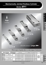
<strong>Soft</strong> <strong>Start</strong>-<strong>up</strong> <strong>Valve</strong><strong>Series</strong> <strong>AV2000</strong>/<strong>3000</strong>/<strong>4000</strong>/<strong>5000</strong>AV<strong>5000</strong><strong>Start</strong>-<strong>up</strong> valve for low speed air s<strong>up</strong>ply to gradually raiseinitial pressure in an air system and for quick exhaust bycutting off air s<strong>up</strong>ply.Large effective area (mm 2 )<strong>AV2000</strong>/ 20 (Body size: 1/4)AV<strong>3000</strong>/ 37 (Body size: 3/8)AV<strong>4000</strong>/ 61 (Body size: 1/2)AV<strong>5000</strong>/ 113 (Body size: 3/4)AV<strong>5000</strong>/ 122 (Body size: 1)Combination with F.R.L. unitF.R.L. combination<strong>Soft</strong>start-<strong>up</strong> valve<strong>AV2000</strong>AV<strong>3000</strong>AV<strong>4000</strong>(Except AC40-06)AV<strong>5000</strong>AC20 AC25 AC30 AC40AC50AC60With s<strong>up</strong>ply/exhaust function by manual operationLow power consumptionConnectable with modular typeF.R.L. combination unitF.R.L. combination<strong>Soft</strong> start-<strong>up</strong>valveACAFARALAWAGAVAF800AF900435
<strong>Soft</strong> <strong>Start</strong>-<strong>up</strong> <strong>Valve</strong><strong>AV2000</strong>/<strong>3000</strong>/<strong>4000</strong>/<strong>5000</strong>How to Order<strong>Soft</strong> start-<strong>up</strong> valveAV 20 00 02 1 GBody size203040501/43/81/23/4,1Manual overrideNil: Non-lockingpush type(Flush)Flow directionNil Left to rightR Right to leftB: Locking type(Tool required)C: Locking type(Lever)Thread typeNilFNRcGNPTLight/Surge voltage s<strong>up</strong>pressorNilSZNoneWith surge voltage s<strong>up</strong>pressor (Grommet type only)With light/surge voltage s<strong>up</strong>pressor (Not possible with grommet type)0203040610Port size1/4 (<strong>AV2000</strong> only)3/8 (AV<strong>3000</strong> only)1/2 (AV<strong>4000</strong> only)3/4 (AV<strong>5000</strong> only)1 (AV<strong>5000</strong> only)NilGOptionNoneWith pressure gaugeCoil rated voltage12345679100 VAC (50/60 Hz)200 VAC (50/60 Hz)110 to 120 VAC (50/60 Hz)220 VAC (50/60 Hz)24 VDC12 VDC240VAC (50/60 Hz)OtherElectrical entryG: GrommetD: Type DDIN terminal (With connector)How to Order Pilot <strong>Valve</strong> AssemblySF41 G 80DO: Type DDIN terminal (Without connector)Y: Type YDIN terminal (With connector)GDYDOYO436Rated coil voltage12345679100 VAC (50/60 Hz)200 VAC (50/60 Hz)110 to 120 VAC (50/60 Hz)220 VAC (50/60 Hz)24 VDC12 VDC240 VAC (50/60 Hz)OtherElectrical entryGrommetType D DIN terminal (With connector)Type Y DIN terminal (With connector)Type D DIN terminal (Without connector)Type Y DIN terminal (Without connector)<strong>Soft</strong> start-<strong>up</strong> valveLight/Surge voltage s<strong>up</strong>pressorNilSZManual overrideNilBCNoneFlow directionNil Left to rightR Right to leftNon-locking push type (Flush type)Locking type (Tool required)Locking type (Lever type)With surge voltage s<strong>up</strong>pressor (Grommet type only)With light/surge voltage s<strong>up</strong>pressor(Not possible with grommet type)TÜV RheiniandBAUARTGEPRÜFTTYPEAPPROVEDYO: Type YDIN terminal (Without connector)Note) The grommet type can have a surge voltages<strong>up</strong>pressor (direct co<strong>up</strong>ling type lead wire), butwithout indicator light.TÜV approved productConforms to standards necessaryto satisfy EC directives.<strong>Series</strong> AV has received approval from TÜV Rheinland, anEC Notified Body (EC authorization number 0197), forconformity to DIN VDE0580: 1994 Standards.Please consult with <strong>SMC</strong> for details when ordering TÜVapproved products because of restrictions regarding productmodel, voltage specification, and electrical entry, etc.
<strong>Soft</strong> <strong>Start</strong>-<strong>up</strong> <strong>Valve</strong> <strong>Series</strong> <strong>AV2000</strong>/<strong>3000</strong>/<strong>4000</strong>/<strong>5000</strong>SpecificationsType D DIN terminalModelPort sizeProof pressureOperating pressure rangePressure gauge port sizeAmbient and fluid temperatureEffective area 1(P) 2(A)(mm 2 ) 2(A) 3(R)Mass (kg)Rated coil voltageAllowable voltage fluctuationCoil insulation typeApparent power InrushAC(Current consumption) EnergizedCurrent consumption DCElectrical entryOption specificationsElectrical specificationsPilot valve manual override<strong>AV2000</strong>1/420240.27Piston B Switching Pressure (CloseAV<strong>3000</strong>3/837490.48AV<strong>4000</strong>1/21.5 MPa0.2 to 1 MPa1/861760.74AV<strong>5000</strong>3/4 11131321.601221411.54100, 200, 110 to 120, 220 VAC (50/60 Hz), 240 VAC (50/60 Hz) 12, 24 VDC–15 to +10% of rated voltageEquivalent to B type (130°C)5.6 VA (50 Hz), 5.0 VA (60 Hz)3.4 VA (2.1 W)/50 Hz, 2.3 VA (1.5 W)/60 Hz1.8 WGrommet, Type D DIN terminal, Type Y DIN terminalIndicator light/Surge voltage s<strong>up</strong>pressor (2)Non-locking push type (Flush),Locking type (Tool required), Locking type (Lever)Note 1) Use dry air when operating at a low temperature.Note 2) The grommet type is equipped with a surge voltage s<strong>up</strong>pressor (direct co<strong>up</strong>ling type lead wire),but not an indicator light.Open)0 to 60°C (1) AV<strong>4000</strong>0.5Type Y DIN terminalOutlet pressure (MPa)0.40.30.20.100.1 0.2 0.3 0.4 0.5 0.6 0.7 0.8 0.9 1.0Inlet pressure (MPa)JIS Symbol1(P)Accessory/Pressure GaugeDescriptionPart no.Pressure range3(R)212(A)Pressure gaugeG36-10-011 MPaNeedle <strong>Valve</strong> Flow CharacteristicsAir flow rate (l/min (ANR))200018001600140012001000800600400Inlet pressure 0.5 MPaAV<strong>5000</strong>AV<strong>3000</strong><strong>AV2000</strong>20000 1 2 3 4 5Needle rotations437ACAFARALAWAGAVAF800AF900
<strong>Series</strong> <strong>AV2000</strong>/<strong>3000</strong>/<strong>4000</strong>/<strong>5000</strong>Working Principle2341ONOFFB5B-B1(P)2(A)763(R)BWorkingconditionPilotvalvePressureconditionsWorking descriptionPressure time chart(Meter-out control) exampleCylinder drive circuit(Meter-out control) exampleLow speeds<strong>up</strong>plyHigh speeds<strong>up</strong>plyON1/2 PP > PA1/2 PP ≤ PAWhen pilot valve 2 is turned ON byenergization or manual override, thepilot air pushes piston A 3 and mainvalve 1 downward and opens mainvalve 1 while R port closessimultaneously. The air from Pport moves to needle valve 7 , whereits flow is adjusted, and flows to A port.The meter-in control of needle valve 7slowly moves the cylinder from A to B .When 1/2 PP ≤ PA after the cylinderreaches B , piston B 5 fully opens andPA increases rapidly as shown from C toD and becomes the same pressure asPP.Initial Operation Return StrokePressure strokeAPPPACylinder movement with fixed orificePR (Atmospheric pressure)TimeCBDPP1(P)PP1(P)3(R)212PA2(A)PA12(A)Normaloperation1/2 PP ≅ PASince piston B 5 holds the fully open condition, during normal operation thecylinder’s speed will be controlled by the usual meter-out control.3(R)QuickexhaustOFF—When pilot valve 2 is turned OFF, spring 4 pushes piston A 3 and main valve1 <strong>up</strong>ward and opens R port while shutting off the air s<strong>up</strong>ply from P port.The pressure difference generated at this time lets the check valve 6 open andthe residual pressure on the A port side is quickly exhausted from R port.1(P)PP21PA2(A)3(R)438
<strong>Soft</strong> <strong>Start</strong>-<strong>up</strong> <strong>Valve</strong> <strong>Series</strong> <strong>AV2000</strong>/<strong>3000</strong>/<strong>4000</strong>/<strong>5000</strong>Construction4151835911ONOFFB12619B-B1(P)2(A)107181416173(R)B132Component PartsNo.123DescriptionBodyCapCoverMaterialAluminum die-castedAluminum die-castedAluminum die-castedReplacement PartsNo.45678910111213141516171819DescriptionPilot valve assemblyPiston A assemblyPiston B assemblyMain valve assemblyCheck valvePiston guide assemblyNeedle assembly<strong>Valve</strong> springPiston springCheck springNeedle springType C retaining ring for shaftType C retaining ring for holeSealSealO-ringMaterialPOM, NBRBrass, NBR (HNBR)Brass, NBR (HNBR)Brass, NBR (HNBR)POM, NBRBrass, NBRSteel wireStainless steelStainless steelSteel wireTool steelTool steelNBRNBRNBR∗1 For “How to Order” pilot valve assembly, refer to page 436.<strong>AV2000</strong>P424204AP424205AP424206AP424207P424208AP424209AP424211P424212P424213P424214G-50-9P424210P42421810 x 8 x 1AV<strong>3000</strong>P424304AP424305AP424306AP424307P424308AP424309AP424311P424312P424313P424314STW-50-10P424310P42431511 x 9 x 1Part no.AV<strong>4000</strong>P424404AP424405AP424406AP424407SF4--80 ∗1 439P424408AP424409AP424411P424412P424413P424414STW-8RTW-12P424410P42441512.5 x 9.5 x 1.5AV<strong>5000</strong>P424504AP424505AP424506AP424507P424508AP424509AP424511P424512P424513—STW-10RTW-15P424510P42451416.5 x 12.5 x 2ACAFARALAWAGAVAF800AF900
<strong>Series</strong> <strong>AV2000</strong>/<strong>3000</strong>/<strong>4000</strong>/<strong>5000</strong>DimensionsGrommet: AV00--G, GSDIN terminal: AV00--D, DZDIN terminal for European use: AV00--Y, YZIGA300 mm (Lead wire length)Manual override(Locking lever type)GLKAMApplicable cab tire cord O.D.: ø6, ø8Manual override (Locking lever type)With light/surgevoltage s<strong>up</strong>pressorPressure gaugemountingbore 1/8Port sizeON OFF ON OFFBIndicator lightPQNø37CBAHPAQHCø37RP4 x R36.8 EPressure gaugemountingbore 1/8RP4 x R 36.8 EDD-+<strong>SMC</strong>MADE IN JAPAN- +<strong>SMC</strong>MADE IN JAPANModelPortsizeA B C D E G H IK L M N P Q R<strong>AV2000</strong>-02-G<strong>AV2000</strong>-02-GS<strong>AV2000</strong>-02-D<strong>AV2000</strong>-02-DZ<strong>AV2000</strong>-02-Y<strong>AV2000</strong>-02-YZAV<strong>3000</strong>-03-GAV<strong>3000</strong>-03-GSAV<strong>3000</strong>-03-DAV<strong>3000</strong>-03-DZAV<strong>3000</strong>-03-YAV<strong>3000</strong>-03-YZAV<strong>4000</strong>-04-GAV<strong>4000</strong>-04-GSAV<strong>4000</strong>-04-DAV<strong>4000</strong>-04-DZAV<strong>4000</strong>-04-YAV<strong>4000</strong>-04-YZ06AV<strong>5000</strong>- 10 -G06AV<strong>5000</strong>- 10 -GS06AV<strong>5000</strong>- 10 -D06AV<strong>5000</strong>- 10 -DZ06AV<strong>5000</strong>- 10 -Y06AV<strong>5000</strong>- -YZ101/41/41/43/83/83/81/21/21/23/4, 13/4, 13/4, 166666676767698989812812812810512512511213213212714714715517517531313136363647474759595922222224242432323239393940404048484852525274747438383843434357575777777700022233<strong>3000</strong>47.5——50.5——62.5——74———65.5—67.5——66.5—70.5——78.5—82.5——90—94———80.5—84.5——83.5—87.5——95.5—99.5——107—111—62310.527.5——163.520.5——6—10.5—————93——100——115——143——29292928282842424250505023.523.523.527.527.527.5373737464646M4 x 0.7Depth 4.5M4 x 0.7Depth 4.5M4 x 0.7Depth 4.5M5 x 0.8Depth 5M5 x 0.8Depth 5M5 x 0.8Depth 5M6 x 1Depth 6M6 x 1Depth 6M6 x 1Depth 6M6 x 1Depth 7.5M6 x 1Depth 7.5M6 x 1Depth 7.5440
<strong>Soft</strong> <strong>Start</strong>-<strong>up</strong> <strong>Valve</strong> <strong>Series</strong> <strong>AV2000</strong>/<strong>3000</strong>/<strong>4000</strong>/<strong>5000</strong>Connecting Spacer for Modular Style F.R.L. UnitSelect one of the spacers below when connecting to an F.R.L. combination unit (AC20 to AC60).(Spacers must be ordered separately.)SpacerSpacer with bracketY200Y400Y200TY400TModelY200Y300Y400Y600Applicable model<strong>AV2000</strong>AV<strong>3000</strong>AV<strong>4000</strong>AV<strong>5000</strong>ModelY200TY300TY400TY600TApplicable model<strong>AV2000</strong>AV<strong>3000</strong>AV<strong>4000</strong>AV<strong>5000</strong>ACAFARALAWAGAVAF800AF900441
<strong>Series</strong> <strong>AV2000</strong>/<strong>3000</strong>/<strong>4000</strong>/<strong>5000</strong>Specific Product Precautions 1Be sure to read before handling. Refer to front matters 42 and 43 for Safety Instructionsand pages 287 to 291 for F.R.L. Precautions.WarningWarningCaution on Design1. Actuator driveWhen using solenoid valve or actuator in the outlet side of thisproduct, implement appropriate measures to prevent potentialdanger caused by actuator operation.2. Holding pressureSince the valve might have slight interal leakage, it is notsuitable for holding pressure in a tank or another vessel for along period of time.3. Maintenance spaceAllow the sufficient space for maintenance and inspection.Selection1. Confirm the specifications.The products presented in this catalog are designed only foruse in compressed air systems. Do not operate at pressuresor temperatures, etc., beyond the range of specifications, asthis can cause damage or malfunction. (Refer tospecifications.) Please contact <strong>SMC</strong> if using for other fluidsthan compressed air.2. Extended periods of continuous energizationPlease contact <strong>SMC</strong> if valves will be continuously energizedfor extended periods of time.3. Operation of closed center solenoid valvesEven if this product is used for closed center solenoid valvesor actuator with a load factor of more then 50%, jumping(stick-slip phenomenon) cannot be prevented.4. Using a regulator in the outlet sideWhen mounting a regulator in the outlet side (A port side), usea residual pressure relief regulator (AR25K to 40K) or a checktype regulator. With a standard regulator (AR10 to 60), theoutlet side pressure may not be released when this valve isexhausted.5. Operation of solenoid valves in the outlet sideTo operate solenoid valves mounted on this product’s outletside (A port side), first confirm that the outlet side’s pressure(PA) has increased to become equal to the inlet side’spressure (PP).6. OperationThe residual pressure release function of this product is foremergency use only; therefore, avoid the operation in thesame manner as ordinary 3 port valves.7. Using a lubricatorIf mounting a lubricator, mount it on the inlet side (P port side),of this product. If mounted on the outlet side (A port side),back flow of oil will occur and may spurt out of the valve’s Rport.8. Operation for air blowingThis product cannot be operated for air blowing due to themechanism that switches the main valve to be fully open afterthe outlet side’s pressure increases to approximately 1/2 of theinlet side.CautionSelection1. Voltage leakageParticularly when using a C-R element (surge voltages<strong>up</strong>pressor) for protection of the switching element, use cationthat leakage voltage will increase due to leakage currentflowing through the C-R element, etc.Powers<strong>up</strong>plySwitching elementOFFResistorLeakage currentAC coil is 20% or less of rated voltage.DC coil is 3% or less of rated voltage.2. Low temperature operationAlthough the valve can be operated at temperature as low as0°C, measures should be taken to avoid solidifying or freezingdrainage and moisture, etc.WarningCautionLeakagevoltageMounting1. If air leakage increases or equipment does notoperate properly, stop operation.After mounting or maintenance, etc., connect the compressedair and power s<strong>up</strong>plies, and perform appropriate function andleakage tests to confirm that the unit is mounted properly.2. Instruction manualMount and operate the product after reading the manualcarefully and understanding its contents. Also keep themanual in a place where it can be referred to as necessary.3. Painting and coatingWarnings or specifications printed or labeled on a productshould not be erased, removed or covered <strong>up</strong>.Furthermore, please contact <strong>SMC</strong> before painting the resinparts, as this may cause adverse effects depending on thesolvent.Adjustment1. To perform the initial speed adjustment of a outletside actuator, s<strong>up</strong>ply air from this valve’s inlet sideand turn ON the pilot valve. Then, rotate the needlecounterclockwise from the fully closed position.<strong>Valve</strong>442
<strong>Series</strong> <strong>AV2000</strong>/<strong>3000</strong>/<strong>4000</strong>/<strong>5000</strong>Specific Product Precautions 2Be sure to read before handling. Refer to front matters 42 and 43 for Safety Instructionsand pages 287 to 291 for F.R.L. Precautions.CautionPiping1. Preparation before pipingBefore piping is connected, it should be thoroughly blown outby air (flushed) or washed to eliminate cutting chips, cuttingoil, and other debris from the pipe inside.2. How to wrap a pipe tapeWhen connecting pipes and fittings, etc., ensure that cuttingchips and sealing materials from the pipe threads should notget inside the valve. When a pipe tape is used, leave 1.5 to 2thread ridges exposed at the end of the pipe.WindingdirectionPipe tapeLight/Surge Voltage S<strong>up</strong>pressorCautionTightening Torque when PipingConnection threadsRc 1/4Rc 3/8Rc 1/2Rc 3/4Rc 1Expose approx. 2 threadsVoltage AC and 100 VDC 24 VDC or lessElectricalcircuitTerminal no. 1 (+)ZNRCautionWith indicator lightTerminal no. 2 (–)Terminal no. 1 + (–)+(–)-(+)Electrical ConnectionZNRWith indicator lightTerminal no. 2 – (+)Note) There is no polarity (+ or –)The internal connection of the DIN terminal is as shown below,connect to the power s<strong>up</strong>ply side as shown.3. Tighten threads with the proper tightening torque.When screwing fittings into valves, tighten with the torquesgiven below.Proper tightening torque (N·m)12 to 1422 to 2428 to 3028 to 3036 to 38TerminalDIN terminalDIN terminal1 21+2–4. Piping to productsWhen piping to products, avoid making an error of s<strong>up</strong>ply port,etc., by referring to the instruction manuals.5. F.R.L. module combinationWhen connecting to a modular F.R.L. combinations (AC20 to60), select one of the spacers, which are included. (Refer topage 441 for details.) However, modular combinations withAC40-06 are not possible.Furthermore, connect soft start-<strong>up</strong> valves to the outlet side ofthe F.R.L. combination.6. Inlet side piping conditionsThe nominal size of the piping material’s or equipment’s boreshould be equal to or larger than the soft start-<strong>up</strong> valve’s portsize. The composite effective area of the inlet side’s (P portside’s) piping or equipment should be equal to or larger thanthe values below.Model<strong>AV2000</strong>AV<strong>3000</strong>AV<strong>4000</strong>AV<strong>5000</strong>Composite effective area (mm 2 )5223550When the piping is restricted or the s<strong>up</strong>ply pressure isinsufficient, the main valve will not switch and air leakage mayoccur from the R port.CautionLubrication1. The valve has been lubricated for life at the factory, and doesnot require any further lubrication.2. Use turbine oil Class 1, ISO VG32 (with no additives), iflubricated. Besides, if the lubrication is suspended halfway,the original lubricant will be lost and may result in amalfunction. Be sure to keep lubricating continuously.Refer to the brand name table given below for lubricants byeach company, comforming to turbine oil Class 1 (with noadditives), ISO VG32.Turbine Oil Class 1 (With no additives), ISO VG32ViscosityclassificationcSt (40°C)ISOviscositygrade32Idemitsu Kosan Co.,Ltd. Turbine oil P-32Turbine oil 32,Nippon Mitsubishi Oil Corp.Mitsubishi Turbine 32Cosmo Oil Co.,Ltd. Cosmo turbine 32Japan Energy Corp. Kyodo turbine 32ViscosityclassificationcSt (40°C)ISOviscositygradeKygnus Oil Co.Turbine oil 32Kyushu Oil Co. Stork turbine 32Showa Shell Sekiyu K.K. Turbine 32Tonengeneral Sekiyu K.K. General R turbine 32Fuji Kosan Co.,Ltd. Fucoal turbine 32Please contact <strong>SMC</strong> regarding turbine oil Class 2 (withadditives), ISO VG32.32ACAFARALAWAGAVAF800AF900443
<strong>Series</strong> <strong>AV2000</strong>/<strong>3000</strong>/<strong>4000</strong>/<strong>5000</strong>Specific Product Precautions 3Be sure to read before handling. Refer to front matters 42 and 43 for Safety Instructionsand pages 287 to 291 for F.R.L. Precautions.WarningCautionWarningAir S<strong>up</strong>ply1. Use clean air.Do not use compressed air which contains chemicals,synthetic oils containing organic solvents, salts or corrosivegases, etc., as this can cause damage or malfunction.1. Install air filters.Install air filters close to valves at their <strong>up</strong>stream side. Afiltration degree of 5 μm or less should be selected.2. Implement countermeasures by installing aftercooleror air dryer, or water separator, etc.The air including excess drain may result in a malfunction ofvalves and other pneumatic equipment. Implementcountermeasures by installing after-cooler or air dryer, orwater separator, etc.Operating Environment1. Do not use valves in such environments wherecorrosive gases, chemicals, or brine or water orsteam is airborne, or where valves can be directlyexposed to any of those.2. Do not use in an explosive environment.3. Do not use in locations influenced by vibrations orimpacts.4. A protective cover, etc., should be used to shieldvalves from direct sunlight.5. Shield valves from radiated heat generated bynearby heat sources.6. Take suitable protective measures in locationswhere there are contacts with water droplets, oil, orwelding spatter, etc.7. In a dusty environment or when valve switchingnoise is intrusive, install a silencer in the R port toprevent dust from entering, and to reduce noise.WarningCautionMaintenance1. Perform maintenance and inspection as shown inthe instruction manual.If handled improperly, damage may occur in machine orequipment or an operational error may result in.2. Equipment removal and s<strong>up</strong>ply/exhaust ofcompressed airWhen equipment is removed, first confirm that measures areimplemented to prevent dropping of workpiece and runaway ofequipment, etc. Then cut the s<strong>up</strong>ply pressure and power, andexhaust all compressed air from the system using its residualpressure release function.3. Low frequency operation<strong>Valve</strong>s should be switched at least once every 30 days toprevent malfunction. (Use caution regarding the air s<strong>up</strong>ply.)4. Manual override operationWhen the manual override is operated, connected equipmentwill be actuated.Confirm the safety before operating.1. Drain removalRemove drain from air filters periodically.How to Find the Flow RateChoke flow: (P2 + 0.1)/(P1 + 0.1) ≤ 0.5Q = 120 x S x (P1 + 0.1) x293273 + tSubsonic flow: when (P2 + 0.1)/(P1 + 0.1) > 0.5Q = 240 x S x(P1 – P2)(P2 + 0.1) xQ: Air flow rate [l/min (ANR)]S: Effective area (mm 2 )P1: Inlet pressure [MPa]P2: Outlet pressure [MPa]t: Air temperature [°C](At air temperature of 20°C)293273 + tNote 1) Formulas above are applied to pneumatics only.444