Cantilever - Chris Alston's Chassisworks
Cantilever - Chris Alston's Chassisworks
Cantilever - Chris Alston's Chassisworks
- No tags were found...

You also want an ePaper? Increase the reach of your titles
YUMPU automatically turns print PDFs into web optimized ePapers that Google loves.
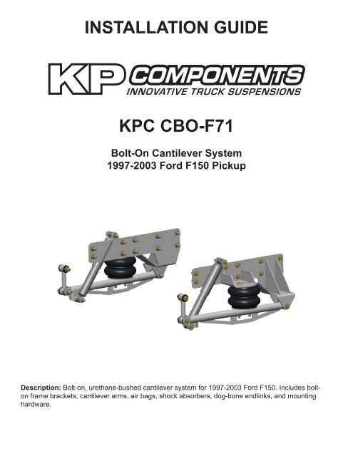
INSTALLATION GUIDEKPC CBO-F71Bolt-On <strong>Cantilever</strong> System1997-2003 Ford F150 PickupDescription: Bolt-on, urethane-bushed cantilever system for 1997-2003 Ford F150. Includes boltonframe brackets, cantilever arms, air bags, shock absorbers, dog-bone endlinks, and mountinghardware.
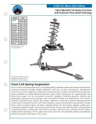
PARTS LISTKPC CBO-F71 - Bolt-on <strong>Cantilever</strong> System, ‘97-03 F150Qty Part Number Description1 7931-016 26” cantilever bar, 2-1/2” shock mount, driver side1 7931-017 26” cantilever bar, 2-1/2” shock mount, passenger side1 7931-045 <strong>Cantilever</strong> frame-bracket weldment, driver side1 7931-046 <strong>Cantilever</strong> frame-bracket weldment, passenger sideKPC CDL-XX - <strong>Cantilever</strong> Dog-bone LinkQty Part Number Description1 7931-XXX Dog-bone link weldment (part number is based on selected tire size)7926-CBOF71 - Hardware BagQty Part Number Description4 3100-038C1.00Y Bolt 3/8-16 x 1” hex head cap screw20 3100-050C1.50Y Bolt 1/2-13 x 1-1/2” hex head cap screw2 3100-050C3.00Y Bolt 1/2-13 x 3” hex head cap screw2 3100-050C3.50Y Bolt 1/2-13 x 3-1/2” hex head cap screw2 3100-056C3.00Y Bolt 9/16-12 x 3” hex head cap screw2 3100-056C3.25Y Bolt 9/16-12 x 3-1/4” hex head cap screw2 3100-056C4.00Y Bolt 9/16-12 x 4” hex head cap screw4 3101-038-16C Locknut 3/8-16 nylon insert24 3101-050-13C Locknut 1/2-13 nylon insert6 3101-056-12C Locknut 9/16-12 nylon insert4 3108-038L-C Lock washer 3/8” regular4 3140-1824-056 Sleeve 9/16 ID x 3/4 OD x 1-3/4” long2 3140-1824-080 Sleeve 9/16 ID x 3/4 OD x 2-1/2” long8 3141-2440-0.88 Poly bushing .75 bore x .875” OAL4 3141-2440-1.19 Poly bushing .75 bore x .1.188” OAL2 3151-1/2OZ Poly lube 1/2 oz. cup8 3157-038S-C Washer flat 3/8” SAE plated44 3157-050S-C Washer flat 1/2” SAE plated12 3157-056S-C Washer flat 9/16” SAE plated4 3163-06C-3.00B Stud 3/8-16 x 3.0" OAL2 7931-084 Spacers 1-1/4 x 1/2 x .300” long4 899-044.51-1.36 Steel washer .510 ID x 1.360 OD x .105” thick platedShock and Bag OptionsQty Part Number Description2 KPC SANS-UCR Shock, steel body1 VAS 12122-715 VariShock, billet-aluminum body, single adjustable1 VAS 12222-715 VariShock, billet-aluminum body, double adjustable2 3470-SS7 Air bag, 250 psi, 7” diameter (optional)
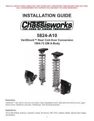
1. Raise the truck and support with jackstands placed under the frame, between thecab and front of the bed mounting brackets.2. Remove the rear bumper and the bed.The 4-link kit must be installed before installingthe cantilever kit.Note: Photos shown may not match your exactapplication.3. The rear leaf-spring bracket must beremoved by taking out the factory rivets.INSTRUCTIONS4. Remove each rivet head using a cuttingtorch or by using a cutoff wheel to grind adeep “X” into the heads of the rivets, andthen removing the rivet head with an airchisel.5. Once the rivet heads are removed, a roundtipair-hammer tool can be used to drive therivets clear of the bracket and frame.
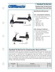
6. Using a 1/2” bit, drill out the four rivet holesclosest to the end of the frame rail that wereused to mount the leaf-spring bracket.7. Bolt the driver-side cantilever frame bracketto the frame using four 1/2-13 x 1-1/2” hexbolts, flat washers, and locknuts. Use flatwashers under each bolt head and locknut.Torque to 45 lb-ft.8. Drill the six forward holes in the frame usingthe cantilever frame bracket as a guide.9. Install the remaining six 1/2-13 x 1-1/2” hexbolts, flat washers, and locknuts. Use flatwashers under each bolt head and locknut.Torque to 45 lb-ft.NOTE: The forward two bolts on the driver’s side cantilever bracket also attach the panhard bar bracket(which must be installed at this time) and therefore do need washers.10. Repeat procedure for the passenger side of the truck.11. Press the 1-3/16”-long poly bushings into thecantilever arms until fully seated.12. Apply a small amount of poly lube to the outsideof the 2-1/2” long sleeve and press it into thepoly bushings until centered.
13. Thread the short end of the 3/8” x 3” studs intothe outside holes at the bottom of the air bags.Do not overtighten the studs. Overtightening thestuds will damage the air bag.14. Orient the bag so that the air inlet at the top of thebag goes toward the inside of the frame bracket.15. Mount the air bag to the frame bracketusing two 3/8-16 x 1” bolts, lock washers,and flat washers. Leave the bolts loose atthis time.16. Mount the driver-side cantilever arm to theair bag by inserting the studs through thearm and securing with 3/8-16 locknuts andflat washers. Leave the locknuts loose atthis time.17. Mount the rear cantilever-arm eye into the frame-bracket clevis and secure using 9/16‐12 x 4”hex bolt, flat washers, and locknut. Use a flat washer under the bolt head and locknut. Leavehardware loose at this time.18. Once the cantilever arm is in place you can tighten the upper air bag bolts, lower studs andcantilever bolt.19. Press the 7/8”-long poly bushings into the endsof each dog-bone link until fully seated.20. Apply a small amount of poly lube to the outsideof the 1-3/4”-long sleeves and press it into thepoly bushings until centered.21. Install one end of the dog-bone link into thecantilever-arm clevis using the 9/16-12 x 3-1/4”hex bolt, flat washers, and locknut. There shouldbe washers under the bolt head and locknut.22. Raise the cantilever arm to install the dog-bonelink into the 4-link axle bracket tabs.23. Use 9/16-12 x 3” hex bolt, flat washers, andlocknuts to secure the dog-bone link.24. Tighten all three 9/16” hex bolts on the cantileverarm to 55 lb-ft.25. Repeat steps for the passenger side of the truck.
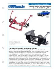
26. Slide the 1.360 OD washer over the1/2‐13 x 3-1/2” hex bolt. Place the bolt throughthe upper shock eye and through thr shockmount boss on the cantilever frame mountbracket. Secure with 1/2” flat washer, andlocknut.27. Slide a 1/2” flat washer onto the 1/2-13 x 3” hexbolt.28. Insert the bolt through the shock mount tab onthe cantilever arm.29. Place the 1-1/4”-OD spacer over the boltfollowed by the shock, 1.360”-OD flat washer,and locknut. Torque to 45 lb-ft.30. This completes the installation.VariShock InstallationFollow the same procedure above for theVarishock adjustable shocks. Note theknobs need to be positioned as shown.WARRANTY NOTICE:There are NO WARRANTIES, either expressed or implied. Neither the seller nor manufacturer will be liable for any loss, damageor injury, direct or indirect, arising from the use or inability to determine the appropriate use of any products. Before any attemptat installation, all drawings and/or instruction sheets should be completely reviewed to determine the suitability of the product forits intended use. In this connection, the user assumes all responsibility and risk. We reserve the right to change specificationwithout notice. Further, <strong>Chris</strong> Alston’s <strong>Chassisworks</strong>, Inc., makes NO GUARANTEE in reference to any specific class legality of anycomponent. ALL PRODUCTS ARE INTENDED FOR RACING AND OFF-ROAD USE AND MAY NOT BE LEGALLY USED ON THEHIGHWAY. The products offered for sale are true race-car components and, in all cases, require some fabrication skill. NO PRODUCTOR SERVICE IS DESIGNED OR INTENDED TO PREVENT INJURY OR DEATH.KP ComponentsA <strong>Chris</strong> Alston’s <strong>Chassisworks</strong> Inc., Brand8661 Younger Creek DriveSacramento, CA 95828Technical Support: KPtech@cachassisworks.com7927-CBOF71 REV 06/18/10