QUALITY INNOVATION SERVICE TRAINING - Bishop Lifting ...
QUALITY INNOVATION SERVICE TRAINING - Bishop Lifting ...
QUALITY INNOVATION SERVICE TRAINING - Bishop Lifting ...
You also want an ePaper? Increase the reach of your titles
YUMPU automatically turns print PDFs into web optimized ePapers that Google loves.
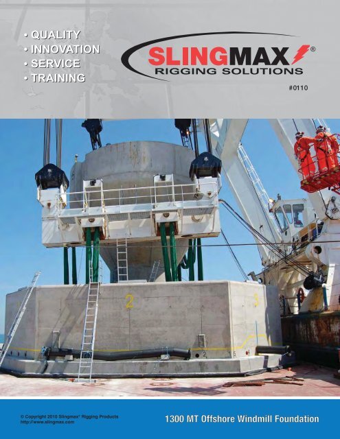
• <strong>QUALITY</strong>• <strong>INNOVATION</strong>• <strong>SERVICE</strong>• <strong>TRAINING</strong>#0110®© Copyright 2010 Slingmax ® Rigging Productshttp://www.slingmax.com1300 MT Offshore Windmill Foundation
Twin-Path ® Extra SlingsWind Farm ConstructionPower Turbine MaintenanceShipbuildingSteam Generator InstallationWARNINGCan fail if damaged, misused or overloaded. Inspect before use. Use only if trained. Do not exceedrated capacity. Protect sling from contact with edges. Avoid exposure to acid, alkali, sunlight andtemperature over 180° F. DEATH or INJURY can occur from improper use or maintenance.
CORDAGEINSTITUTESolutions................................................. 2Slingmax ® Website ................................. 3Twin-Path ® Products.......................... 4-15Twin-Path ® Extra Covermax ® Slings..... 5Check-Fast ® Inspection System........... 6Fiber Optic Inspection.......................... 6Covermax ® Covers............................... 7CornerMax ® Pads ................................ 8CornerMax ® Sleeves............................ 9Shackle Pin Pads............................... 10Synthetic Armor TM Pads ......................10Adjustable Bridles ........................ 12-13Single-Path Check-Fast ® Roundsling .. 14Sparkeater ® Slings............................. 14Two Leg Bridles ................................. 15Eye & Eye Slings ............................... 15Rigging Institute ...............................16-17Table of ContentsInspection & Testing .................................... 19Mechanical Considerations ......................... 20Environmental Considerations .................... 21Wire Rope Products .............................. 24-32Gator-Laid ® Slings .................................... 26Gator-Max ® Slings .................................... 27Gator-Flex ® Slings .................................... 28Gator-Flex ® Grommets ............................. 29Tri-Flex ® Slings.......................................... 30T & D Ultra-Flex TM Slings ........................... 31Pad Eye Tester ............................................ 33G-Link TM Connectors ................................... 34Chain Sling Saddle Ring ............................. 35Definitions of Terms..................................... 36Basic Lift Engineering ................................. 37Innovations .............................................38-39International Distribution ............................. 40CAUTIONS or WARNINGSAll ratings shown in this literature are based upon the items being new orin “as new” condition. These ratings may not be applicable if the sling or fittingis exposed to misuse, overloading, corrosion, wear, deformation, intentional alterationand other usage factors. Catalog ratings are to be the greatest load that shall be appliedto the sling or fitting at the identified hitch confirmation and induced angle. Shock loadingmust be avoided.Follow OSHA and ASME B30.9 guidelines. Review and follow all Manufacturers guidelinesincluding all Mechanical and Environmental Considerations, Inspection Instructions,Warning Literature and Warning Tag Instructions.When in doubt, always consult the manufacturer directly.1
We are Slingmax ® — we provide rigging solutionsWe believe we can solve your rigging problem with oursynthetic solutions, like our Twin-Path ® slings and Check-Fast ®slings, plus sling protection like CornerMax ® pads and sleevesor Synthetic Armor TM pads. But we know there is a large demandfor other rigging, whether it be steel or anothersynthetic. Slingmax ® of course has products forall types of rigging. Our wire rope sling designs arethe highest efficiency multipart wire rope slingsavailable. They include Gator-Max ® , Gator-Laid ® ,Gator-Flex ® , T&D Ultra-Flex TM and Tri-Flex ® slings.Our G-Link TM connectors work with all syntheticslings as do our sling protections. For a versatileand adjustable chain sling, we recommend ourChain Sling Saddle Ring. Our Pad Eye tester canaccommodate a variety of lifting points. And ourRigging Institute training courses cover all typesof rigging.More importantly to you the customer is thatSlingmax ® has a worldwide network of dealers:42 rigging fabrication locations and over120 sales branches. These dealers manufacture anddistribute the best rigging products in a locationnear you.Our Slingmax ® rigging products, plus ourSlingmax ® full-service rigging network,equal SLINGMAX ® RIGGING SOLUTIONSfor you. Look for our dealers when youneed a rigging solution or just the bestin rigging.2
http: //www.slingmax.comThe slingmax.com website is the most current version of any information about SlingmaxInc. and its products and services. Printed material can go out of date and yet remainin your library, but we update the slingmax.com website as soon as new informationbecomes available.In addition to being an online catalog for Slingmax ® Rigging Solutions, our website givesyou access to Technical Bulletins, instructional videos, use and care information, andtechnical articles. All of our print catalogs and brochures are downloadable from the website.So check the website regularly and use it as a technical resource for your rigging plans.3
TWIN-PATH ® SLINGS500 ton Steam Generator Replacement88 ton Refinery Compressor with CornerMax ® PadsMark V Navy Assault BoatRemoval of 500 tonBridge Decking4Reactor Coolant Pump MotorAutomobile Stamping Die
Twin-Path ® Extra Sling with Covermax ®and K-Spec ® Core Yarn (Check-Fast ® Inspection optional)US Patent #4,850,629 & #5,651,572 CN #1,280,458 & #2,195,393Italy #97300367.6 Japan #2929431 Australia #707924TPXC This is the world’s first truly ergonomic sling with Covermax ® covers forsuperior abrasion resistance. These are made in sizes up to 600 tons verticalrated capacity. Larger capacity slings are available on special order. These slingshave overload indicators, inner red cover, and are usedworldwide in place of wire rope slings for heavy lifts. Theyare approximately 10% of the weight of a steel sling. Theseproducts are repairable. The Twin-Path ® patented designprovides the rigger with two connections between the hookand the load for redundant back-up protection. These slingshave less than 1% stretch at rated capacity. If ergonomics,productivity and safety are important, then these slings arethe only choice. This is the lightest and strongest sling onthe market today with K-Spec ® – the longest lasting loadbearing core yarn, backed by independent testing.NOTE: Capacities shown include both paths and are for one complete sling. Sling ratings based on fittings of equal or greater capacity. Conforms toANSI/ASME B30.9 chapter 6, NAVFAC P-307 section 14.6.4.3, and the Cordage Institute Roundsling Standard. This chart is based on a 5:1 Design Factor (DF);but any other DF can be fabricated. Higher capacity slings are available. CAPACITIES ARE IN POUNDS (LBS.).Twin-Path ® SlingStock No.Vertical Choker Vertical Basket Basket Hitches90°60° 45°ApproximateWeight(Lbs. per Ft.)(Bearing-Bearing)NominalBody Width(Inches)*TPXCF/TPXC 1000 10,000 8,000 20,000 17,320 14,140 .40 1.5 - 3˝TPXCF/TPXC 1500 15,000 12,000 30,000 25,980 21,210 .45 1.5 - 3˝TPXCF/TPXC 2000 20,000 16,000 40,000 34,640 28,280 .51 1.5 - 3˝TPXCF/TPXC 2500 25,000 20,000 50,000 43,300 35,350 .57 1.5 - 3˝TPXCF/TPXC 3000 30,000 24,000 60,000 51,960 42,420 .71 2.0 - 4˝TPXCF/TPXC 4000 40,000 32,000 80,000 69,280 56,560 .83 2.0 - 4˝TPXCF/TPXC 5000 50,000 40,000 100,000 86,600 70,700 1.14 2.5 - 5˝TPXCF/TPXC 6000 60,000 48,000 120,000 103,920 84,840 1.27 2.5 - 5˝TPXCF/TPXC 7000 70,000 56,000 140,000 121,240 98,980 1.39 2.5 - 5˝TPXCF/TPXC 8500 85,000 68,000 170,000 147,220 120,190 1.65 3.0 - 6˝TPXCF/TPXC 10000 100,000 80,000 200,000 173,200 141,400 1.84 3.0 - 6˝TPXCF/TPXC 12500 125,000 100,000 250,000 216,500 176,750 2.35 4.0 - 8˝TPXCF/TPXC 15000 150,000 120,000 300,000 259,800 212,100 2.66 4.0 - 8˝TPXCF/TPXC 17500 175,000 140,000 350,000 303,100 247,450 3.14 5.0 - 10˝TPXCF/TPXC 20000 200,000 160,000 400,000 346,400 282,800 3.45 5.0 - 10˝TPXCF/TPXC 25000 250,000 200,000 500,000 433,000 353,500 4.07 5.0 - 10˝TPXCF/TPXC 27500 275,000 220,000 550,000 476,300 388,850 4.61 6.0 - 12˝TPXCF/TPXC 30000 300,000 240,000 600,000 519,600 424,200 4.92 6.0 - 12˝TPXCF/TPXC 40000 400,000 320,000 800,000 692,800 565,600 6.54 7.0 - 14˝TPXCF/TPXC 50000 500,000 400,000 1,000,000 866,000 707,000 8.15 8.0 - 16˝*Dimensions can vary according to the hardware or bearing points the slings are used with. METRIC SLINGS AVAILABLEMinimum is “tapered” width; Maximum is the flat tubing width.TWIN-PATH ® SLINGSWARNINGSling can fail if damaged, misused or overloaded. Inspect before use. Damaged sling shall not be used.Use only if trained. Do not exceed rated capacity. Protect sling from being cut by load edges, corners,protrusions and abrasive surfaces. Avoid exposure to acid, alkali and temperature over 180°F. DEATHor INJURY can occur from improper use or maintenance.5
TWIN-PATH ® SLINGSSEE THEEWIGONO-GOEWIMISSINGCheck-Fast ® Inspection System(also known as the ✓Fast System)Patent #7,661,737 Foreign Patents PendingThe Check-Fast ® System is designed to improve job-site safety.The ✓Fast ® Tag and External Warning Indicator (EWI) on aroundsling product provides for a pass/fail inspection of theinternal load bearing core yarn. Damage to the core yarnfrom ultraviolet (UV) light degradation, fiber on fiber abrasion,fatigue, and severe overload can be detected. If the sling ismistakenly overloaded beyond rated capacity, the EWI isdesigned to disappear before the sling fails. The sling inspectornow has a GO/NO-GO inspection device rather than relying ona subjective hand-over-hand inspection to make an educatedguess if the load bearing core yarns are in good condition. Thissafety system is available for High Performance K-Spec ®Fiber Roundslings or polyester roundslings fabricated byauthorized SLINGMAX ® Dealers.Fiber Optic Inspection for Twin-Path ® SlingsUS Patent #4,850,629 #5,651,572 CN #1,280,458 #2,195,393 Italy #97300367.6 Japan #2929431 Australia #707924Twin-Path ® slings have the Fiber Optic inspectionsystem. The condition of the internal core yarncan be inspected just by checking the continuityof the fiber optic cable. If crushing or cutting,heat or chemical damage, has occurred then thedamage to the fiber optic cable will destroy itsability to transmit light from one end to the othergiving the inspector a reason to remove the slingfrom service and send it in for repair evaluation.The fiber optic cable will conduct light using natural,overhead or flashlight sources. The inspector simplycovers and removes his finger from one end andwatches the other end for blinking which indicatesthat the sling is OK to use for another lift.6WARNINGSling can fail if damaged, misused or overloaded. Inspect before use. Damaged sling shall not beused. Use only if trained. Do not exceed rated capacity. Protect sling from being cut by load edges,corners, protrusions and abrasive surfaces. Avoid exposure to acid, alkali and temperature over 180°F.DEATH or INJURY can occur from improper use or maintenance.
Covermax ® CoversAny Twin-Path ® sling can be made with a Covermax ® cover. This is made of a heavy-duty,double-layer industrial nylon material. The outside cover is green and the inside cover isred. If you see any red showing through the green cover, stop using the sling and get a repairevaluation. This cover has been tested to provide the best ultraviolet (UV) protection andthe best abrasion protection of any commercially available synthetic lifting sling. Below aresummary charts of the cover tests.Roundsling Cover Abrasion Test ResultsDBL Orange PolyDBL Purple PolyDBL Gray PolyCoverMax ® GreenDBL Black PolyDBL Red PolyTWIN-PATH ® SLINGSDBL Green PolyDBL Yellow PolyDBL Brown PolyDBL Blue PolyTHREE EARLY WARNINGS1. Covermax ® covers can be repaired. Over 99% ofTwin-Path ® slings stay in service.2. Fiber optics can be replaced if damaged.3. The Check-Fast ® System and overload tell-tails can bereset or replaced to keep your Twin-Path ® sling in service.ALL REPAIRABLE7
CornerMax ® Pads: Engineered Cut ProtectionPatent PendingCornerMax ® pads create a “tunnel” of cut protection – a no-touch zone. Therefore, the edgedoes not come in contact with the pad or sling thus protecting the sling. Note that the sides ofthe load must completely support the pads in order to create and maintain the “tunnel”.TWIN-PATH ® SLINGSSimulated load edgeCornerMax ®Part No.Sling Width(inches)CornerMax ®Approx. Width(inches)CornerMax ®Approx. Wt.(lbs)CRNMX02 1 & 2 4 1.00CRNMX03 3 5 1.25CRNMX04 4 6 1.50CRNMX05 5 8 2.00CRNMX06 6 8 2.00CRNMX08 8 10 2.50CRNMX10 10 12 3.00CRNMX12 12 16 5.50CRNMX14 14 18 6.50NOTE: All CornerMax ® pads are approximately 9 inches in lengthunless otherwise specified.GOODNOGOODNO8WARNINGCORNERMAX ® PAD CUT PROTECTIONDamaged or misused protection can result in damage or sling failure. Inspect before each use. Inspect forcuts, tears or damage that may prevent protection of the sling. Ensure protection is the correct size and type toprotect the sling. Prevent pads and sling from slipping or sliding across load edge. DEATH or INJURY can occurfrom improper use, maintenance and/or inspection.MAXIMUM LOADING: Do NOT exceed 25,000 lbs. per inch of sling width.
CornerMax ® Sleeves: Engineered Cut ProtectionThe CornerMax ® sleeve is the latest in rigging protection from SLINGMAX ® Rigging Solutions. TheCornerMax ® sleeve is the ideal solution to protect synthetic slings from cutting when it is not practical touse a CornerMax ® pad, whether due to curvature of the load edge or repetitive uses such as unloading steelcoils. Independent field and laboratory testing has shown the CornerMax ® sleeve to be extremely cutresistant. The CornerMax ® sleeve is made with high tech fiber and is proven tough. In some applicationsthe CornerMax ® sleeve may be attached to the sling to prevent slippage. The true benefits of this revolutionarymaterial far outweigh the costs and now provide for the use of synthetic slings in applications previouslydominated by heavy chain, mesh and wire rope slings.CornerMax ® SleevePart No.CRNMXS04CRNMXS10NOTE: Wider sleeves are available.External SleeveWidth6 in.10 in.Twin-Path ® Coil Sling• 10 times lighter than conventional steel coil gripper slings.Fastened overboth legs ofTwin-Path ® SlingUp to TPXC 7,000Up to TPXC 25,000• The Twin-Path ® Coil Sling is so light that it is easy to grab and pull the sling.• Will not damage the load.• Repairable as manufacturer can remove a damaged CornerMax ® sleeve and sew a new oneto the sling.TWIN-PATH ® SLINGS100%Successfully tested to25,000 lbs. per inch of sling width4464 kg. per centimeter of sling width20%CornerMax® PadCornerMax® SleeveNylon WebbingSeat Belt Webbing1/4” Rubber PadLeather PadSpectra® ShieldPerformance Pad(3/8” thick)Kevlar® FeltDouble WallCoverPerformancePad (1/4” thick)Baseline(no protection)% OF BREAK STRENGTHWORKING LOADWARNINGCORNERMAX ® SLEEVE CUT PROTECTIONDamaged or misused protection can result in damage or sling failure. Inspect before each use. Inspect forcuts, tears or damage that may prevent protection of the sling. Ensure protection is the correct size and type toprotect the sling. Prevent sleeve and sling from slipping or sliding across load edge. DEATH or INJURYcan occur from improper use, maintenance and/or inspection.MAXIMUM LOADING: Do NOT exceed 25,000 lbs. per inch of sling width.9
Synthetic Armor TM Pads: Abrasion ProtectionSynthetic Armor TM pads protect slings from abrasion damage which can be caused by contact withrough surfaces such as concrete beams and structures. They are also used to protect finished orpainted loads from marring. These pads can be made to fit any length or width sling. They canalso be made in long lengths which the customer can cut into suitable sizes on the job. Double ortriple thickness provides resistance for the more severe conditions. There is no maximum width anda variety of materials are used to protect slings and to protect loads depending on the degreeof abrasion expected in the application.TWIN-PATH ® SLINGSSYNARM–SL “Sliding”SYNARM–RM “Removable”SYNARM–EE “Eye and Eye”Shackle Pin PadsThe pin area of a shackle can cause synthetic slings to cut or tear. Placingsynthetic slings on the pin should be avoided. Any shackle can have a sharpedge where the threaded pin goes through the shackle ear. If the sling is exposedto this area, it can cut and fail. If you must rig on the pin, protect your sling with aShackle Pin pad.• Sized for the model of shackle.• Protects sling along entire pin including ear seams.• Three connection points secure pad to shackle.• Install and uninstall in seconds.10WARNINGCan cause damage or failure of sling if misused or damaged. Inspect before each use. Inspect for cuts,tears or damage that may prevent protection of the sling. Be sure wear protection is the correct sizeand type to protect the sling. DEATH or INJURY can occur from improper use or maintenance.
100 ton Bridge SectionNuclear Reactor Containment SectionsTWIN-PATH ® SLINGSShipbuilding Module200 ton Experimental Reactor200 ton Electric Transformer220 ton Cement Kiln11
Twin-Path ® Adjustable BridleUS PATENT #4,850,629 Canadian Patent #1,280,458TPXA (with K-Spec ® fiber), TPA (with polyester)This sling is a two-leg bridle with one leg having twice the capacity of the other. Apply tensionto the Twin-Path ® Adjustable bridle until it self-adjusts over the center of gravity. Then makeyour level lift.SPECIALTY SLINGSConstruction EquipmentMilitary AircraftTPACodeTWIN-PATH ® ADJUSTABLE BRIDLE SPECIFICATIONSBridleCapacity(Lbs.)NominalSlingWidthADJUSTABLE RING DIMENSIONS SHACKLE DIMENSIONS SLING WEIGHT (LBS.)RingStockDiameterMain HookArea(Width)RingArea(Length)NominalShackleSizeTonnage(W.L.L.)Approx.3 FootBaseTPA 6 6,000 2˝ 37/64˝ 2-1/2˝ 2-1/4˝ 5/8˝ 3-1/4T 4.40 1.35TPXA 12 12,000 3˝ 13/16˝ 3˝ 2-5/8˝ 7/8˝ 6-1/2T 6.80 1.95TPXA 20 20,000 4˝ 1-1/8˝ 4˝ 3-5/8˝ 1-1/4˝ 12T 13.60 2.70TPXA 40 40,000 5˝ 1-5/8˝ 5 1/4˝ 4-3/4˝ 1-3/4˝ 25T 31.10 4.20TPXA 60 60,000 5˝ 2˝ 7˝ 6-1/4˝ 2˝ 35T 60.00 5.70TPXA 90 90,000 6˝ 2-1/4˝ 8˝ 7-1/4˝ 2-1/4˝ 55T 86.00 8.10PLEASE NOTE: CAPACITIES SHOWN ARE FOR ENTIRE BRIDLE ASSEMBLY WITH THE DOUBLE LEG AT A 45° HORIZONTAL ANGLE.Approx.AdderPer FootMETRIC CAPACITIES AVAILABLEDO NOT EXCEED RATED CAPACITY12WARNINGSling can fail if damaged, misused or overloaded. Inspect before use. Damaged sling shall not be used.Use only if trained. Do not exceed rated capacity. Protect sling from being cut by load edges, corners,protrusions and abrasive surfaces. Avoid exposure to acid, alkali and temperature over 180°F. DEATHor INJURY can occur from improper use or maintenance.
Twin-Path ® Adjustable BridleThe Twin-Path ® Adjustable Bridle Sling is a multi-purpose rigging tool and it’s important that it isused properly. The adjustment ring has a double leg for the heavy side of the load and a singleleg on the lighter side. See the Adjustable Bridle Product Manual for more information.If the lifting points are an equal distance from the center ofgravity then the Twin-Path ® Adjustable can be hooked-upwith the double or single leg on either lifting point.If the lifting points are an equal distance on either side ofthe center of gravity but one is higher, then the double legshould be attached to the higher lifting point.SPECIALTY SLINGSIf one of the lifting points is closer to the center of gravity, thenattach the double leg to this lifting point. It will have thehighest weight concentration. If the Twin-Path ® Adjustable isattached so that the single leg is nearest the center of gravity,the lift cannot be made.The Twin-Path ® Adjustable Bridle should be used in applicationswhere the double leg horizontal angle is greaterthan 45°. Always connect above the center of gravity. Ifconnections are made below the center of gravity, then theload may turn when lifted.WARNINGSling can fail if damaged, misused or overloaded. Inspect before use. Damaged sling shall not be used.Use only if trained. Do not exceed rated capacity. Protect sling from being cut by load edges, corners,protrusions and abrasive surfaces. Avoid exposure to acid, alkali and temperature over 180°F. DEATH orINJURY can occur from improper use or maintenance.13
SINGLE-PATH EXTRA COVERMAX ® WITH CHECK-FAST ® INSPECTIONSingle-PathK-Spec ® SlingsStock No.Check-Fast ®High Performance RoundslingsUS Patent #7,661,737 Foreign Patents PendingThis is the only single-path, high performance fiber roundsling with anoverload indicator. The Covermax ® cover is the most durable available fora synthetic sling. Also available in polyester.Rated Capacities (Lbs.)Vertical Choker Vertical Basket Basket Hitches90°60° 45°ApproximateWeight(Lbs. per Ft.)(Bearing-Bearing)NominalBody Width(Inches)SPECIALTY SLINGSSPXCF 500 5,000 4,000 10,000 8,660 7,070 .34 2.5˝SPXCF 1000 10,000 8,000 20,000 17,320 14,140 .38 2.5˝SPXCF 1500 15,000 12,000 30,000 25,980 21,210 .44 2.5˝SPXCF 2000 20,000 16,000 40,000 34,640 28,280 .52 2.5˝SPXCF 2500 25,000 20,000 50,000 43,300 35,350 .59 3˝SPXCF 3000 30,000 24,000 60,000 51,960 42,420 .65 3˝SPXCF 4000 40,000 32,000 80,000 69,280 56,560 .85 3˝SPXCF 5000 50,000 40,000 100,000 86,600 70,700 .98 4˝SPXCF 6000 60,000 48,000 120,000 103,920 84,840 1.11 4˝SPXCF 7000 70,000 56,000 140,000 121,240 98,980 1.24 4˝SPXCF 8500 85,000 68,000 170,000 147,220 120,190 1.63 5˝SPXCF 10000 100,000 80,000 200,000 173,200 141,400 1.81 5˝DO NOT EXCEED RATED CAPACITYDO NOT EXCEED RATED CAPACITYSparkeater ®US Patent #4,850,629 CN Patent #1,280,458SE When you have a hot environment up to 300°F (200°C), use a Sparkeater ®to lift the load without marring the surface of the lifted piece. Also, when doingstage rigging, order this product with a black cover for the protection it givesfrom exposure to fire, heat, sparks and pyrotechnics. These slings are madefrom aramid high performance core yarns and an aramid cover. The OffshoreCertification Bureau identified these slings as being as good as wire rope or chainfor use in offshore applications in the oil industry. As with all Twin-Path ® slings, aninner red cover provides an early warning safety alert.Rated Capacities (Lbs.)Vertical Choker Vertical Basket Basket HitchesTwin-Path ®Stock No. 90°60° 45°ApproximateWeight(Lbs. per Ft.)(Bearing-Bearing)NominalBody Width(Inches)TPSE 1000 10,000 8,000 20,000 17,320 14,140 .40 1.5 - 3˝TPSE 1500 15,000 12,000 30,000 25,980 21,210 .45 1.5 - 3˝TPSE 2000 20,000 16,000 40,000 34,640 28,280 .51 1.5 - 3˝TPSE 2500 25,000 20,000 50,000 43,300 35,350 .57 1.5 - 3˝TPSE 3000 30,000 24,000 60,000 51,960 42,420 .71 2.0 - 4˝TPSE 4000 40,000 32,000 80,000 69,280 56,560 .83 2.0 - 4˝TPSE 5000 50,000 40,000 100,000 86,600 70,700 1.14 2.5 - 5˝TPSE 6000 60,000 48,000 120,000 103,920 84,840 1.27 2.5 - 5˝TPSE 7000 70,000 56,000 140,000 121,240 98,980 1.39 2.5 - 5˝TPSE 8500 85,000 68,000 170,000 147,220 120,190 1.65 3.0 - 6˝TPSE 10000 100,000 80,000 200,000 173,200 141,400 1.84 3.0 - 6˝METRIC CAPACITIES AVAILABLEDO NOT EXCEED RATED CAPACITYPLEASE NOTE: CAPACITIES SHOWN INCLUDE BOTH PATHS AND ARE FOR ONE COMPLETE SLING.SMALLER AND LARGER CAPACITIES AVAILABLE UPON REQUEST.14WARNINGSling can fail if damaged, misused or overloaded. Inspect before use. Damaged sling shall not be used.Use only if trained. Do not exceed rated capacity. Protect sling from being cut by load edges, corners,protrusions and abrasive surfaces. Avoid exposure to acid, alkali and temperature over 300°F.DEATH or INJURY can occur from improper use or maintenance.
Twin-Path ® Two-Leg BridlesUS Patent #5,727,833 & #4,850,629TL Simply the lightest and strongest synthetic bridles in the worldtoday. These are perfect to replace existing chain and wire ropebridles. The Twin-Path ® synthetic bridle with K-Spec ® core yarnis less than half the weight of any steel assembly. The soft eyeat the top goes on the crane hook and there is no heavy steel ringto deal with. If you need a four-leg bridle, order two Twin-Path ®Two-Leg Bridles.TWIN-PATH ® TWO-LEG BRIDLES (Capacities in lbs.)Stock Numbers Vertical 60° Horizontal Angle (Lbs.) Wt. Per Ft.NominalWidthTPXCTL 1,000 10,000 8,500 .34 3˝TPXCTL 1,500 15,000 12,750 .44 3˝TPXCTL 2,000 20,000 17,000 .61 3˝TPXCTL 3,000 30,000 25,500 .88 4˝TPXCTL 4,000 40,000 34,000 1.23 5˝TPXCTL 5,000 50,000 42,500 1.65 5˝SPECIALTY SLINGSTwin-Path ® Eye & Eye Synthetic SlingUS Patent #5,727,833 & #4,850,629EE Riggers have told us that they have some applicationswhere they want an eye and eye sling only and this is the onewith all of the Twin-Path ® features in a strictly eye and eye product.It is a single-bodied sling with integrated eyes.Stock NumbersTWIN-PATH ® EYE & EYE SLING (Capacities in lbs.)VerticalChokerVerticalBasketBasket60°Wt Lbs.Per Ft.NominalWidthTPXCEE 1,000 10,000 8,000 20,000 17,320 .28 3˝TPXCEE 1,500 15,000 12,000 30,000 25,980 .36 3˝TPXCEE 2,000 20,000 16,000 40,000 36,640 .50 3˝TPXCEE 2,500 25,000 20,000 50,000 43,300 .60 4˝TPXCEE 3,000 30,000 24,000 60,000 51,960 .75 4˝TPXCEE 4,000 40,000 32,000 80,000 69,280 1.00 5˝TPXCEE 5,000 50,000 40,000 100,000 86,139 1.40 5˝METRIC CAPACITIES AVAILABLEWARNINGSling can fail if damaged, misused or overloaded. Inspect before use. Damaged sling shall not be used.Use only if trained. Do not exceed rated capacity. Protect sling from being cut by load edges, corners,protrusions and abrasive surfaces. Avoid exposure to acid, alkali and temperature over 180°F. DEATH orINJURY can occur from improper use or maintenance.15
Slingmax ® Rigging Institute“Synthetic roundsling users shall be trained in the selection, inspection, cautions to personnel, effectsof environment, and rigging practices.” (ASME B30.9-2006 Chapter 9-6)RIGGING <strong>TRAINING</strong>AND SAFETY COURSES<strong>TRAINING</strong>These courses were developed to enable riggingand supervisory personnel to perform their riggingjobs with appropriate knowledge of the equipmentavailable to them and with a safety-consciousnessof their work. All commonly available types of riggingand hardware are covered in the courses. They allreference the applicable regulatory standards for thetopics they cover. While some of the courses wereoriginally designed to be instructor-taught sessions,they can be self-taught. Most of the courses areavailable on multiple media: video, CD and DVD andall attendees will receive certificates of attendance.Introductory RiggingA Riggers Handbook and workbook is provided asreference material for each course participant.This is a starter course for riggers, safety personnel,engineers, and their supervisors.Advanced RiggingThis course consists of modulesthat can be tailored to a company’sneeds from four hours to two full daysof instruction. It is available on CDor DVD and covers such topics as:load control, sling loading, andrigging design. A workbook followsthe course topics and is accompaniedby the Slingmax ® Riggers Handbook.16
Slingmax ® Rigging InstituteSLING ANDRIGGING HARDWAREINSPECTION COURSESIntroductory InspectionThis is a starter course for quality assuranceinspectors, sales people, supervisors, andriggers who want to know how to inspecttheir equipment. The course is 50 minuteslong and is available on video and DVD.Sling and Hardware Inspection<strong>TRAINING</strong>This advanced course is independent of the rigging training and safety courses because rigginghardware inspectors do not have to be riggers. This course is available on CD and DVD with aworkbook. Inspectors have an answer key and a list of samples required to make this course ahands-on experience for the participants.TRAIN-THE-TRAINERCOURSEThis course is available as an instructortaughtcourse only. It trains instructorsto teach the two advanced courses.In addition to the technical coursematerials, it includes topics such asworkshop structure and training andcommunication techniques. It requiresthree full days.Contact your SLINGMAX ® Rigging Solutions dealer for more information or to set up a courseat their facility or yours. Please inform your dealer of the type of course desired, number ofparticipants, training level of participants and a range of possible dates.17
FLIP OVER TWIN-PATH ® SLINGSShip ModuleElectric Generator RecoveryElectric Generator/StatorNuclear Reactor Head Turning18Test Reactor RemovalSubsea Stack/Tree Laydown
Inspections of Twin-Path ® Products1. Check-Fast ® Early Warning Indicator (EWI) and Tell-Tail indicators shall extend past the tag area of eachsling. If your sling is equipped with Check-Fast ® and the EWI is not visible or both Tell-Tails are not visible,remove the sling from service. Send to manufacturer for repair evaluation.2. If Fiber-Optic inspection is installed in the sling, inspect by allowing light to enter the fiber optics. Ifthe fiber optics do not transmit light from end to end, remove the sling from service and contact themanufacturer for repair evaluation.3. Slings shall be inspected for evidence of cutting or tearing of the outer cover. Slings with cuts shall beremoved from service and sent back to the manufacturer for repair evaluation. Damage to the cover mayindicate core damage.4. Inspect slings for evidence of heat damage. Sparkeater ® slings shall not be exposed to temperaturesover 200°C/300°F. K-Spec ® and polyester slings shall not be exposed to temperatures above82°C/180°F. Cold temperature exposure down to minus 40°C/minus 40°F do not affect the strength ofthe products.5. If any part of the sling shows evidence of chemical degradation or damage, remove the sling from service.Return the sling to the manufacturer for repair evaluation.6. Slings using aluminum fittings shall not be used where fumes, vapors, sprays or mists of alkalis or acidsare present.7. Twin-Path ® lifting slings and any fittings attached shall be the subject of frequent and regular inspections. Inaddition to the initial inspection by a competent person and frequent written inspections, the slings shallbe visually inspected before each use.8. Written inspections shall be performed as required and documents of such inspection by a competentperson shall be kept on file in the safety department of the plant or site where used. Inspections may bedone more often based on frequency of use, severity of conditions, experience of past service life.9. Slings shall be examined throughout their length for abrasion, cuts, heat damage, fitting distortionor damage, tag legibility, and if any doubts are held by the inspector, the sling shall be removed fromservice. If deterioration is found, the sling must be removed from service.10. Slings removed from service that are not repairable shall be destroyed and rendered completely unfit forfuture use.11. Abrasion, heat damage or cuts to the cover may indicate a loss of strength to the core yarns, and theseslings shall not be used until evaluated by the manufacturer.USE AND CARETest Procedures for Twin-Path ® Sling Products1. Proof tests shall consist of pulling the slings to twice their rated capacity.2. Testing of Twin-Path ® sling products and core yarn shall be on a testing machine which meets or exceedsthe standards as described in ASME E-4.3. Break testing of slings shall be as above with results documented. Pin size for break testing should be adiameter equal to half the nominal sling width, or larger.4. Repaired fittings or slings shall be proof-tested before they are returned to service. Certifications maybe provided to the fitting or sling owner.19
Mechanical Considerations1. Load both paths of Twin-Path ® slings equally. Do not side load. Do not load the edge of the sling.2. Determine the weight of the load. The weight of the load shall be within the rated capacity of the sling.3. Select a sling having suitable characteristics for the type of load, hitch and environment.4. Slings shall not be loaded in excess of the rated capacity. Consideration shall be given to angle of liftwhich may affect the lifting capacity. Diameters of pins and edges also may affect the capacity of thelifting sling.USE AND CARE5. Slings used in a choker shall not be forced to tighten around the load by pounding with hammers orother objects. Choker hitches are the least effective way to use a sling based on capacity. Two chokersshould be used to balance the load. One choker in the center of the load may create an unbalancedsituation which could lead to an accident.6. Slings used in a basket hitch must have the load balanced to prevent slippage and accidents.7. Slings used with fittings shall be compatible with the fittings used. The lifting capacity shall berated at the lower of the fitting or sling. Fitting openings shall be of the proper shape and size to assurethat the sling will seat properly.8. Slings in contact with edges, corners, protrusions, or abrasive surfaces shall be protected with amaterial of sufficient strength, thickness, and construction to prevent damage. The pin area of ashackle can cause synthetic slings to cut or tear.9. Slings shall not be dragged on the floor or drawn across other surfaces which may damagethe sling.10. Slings shall not be twisted or tied in knots to shorten.11. Slings can be damaged by resting loads on them or by pulling slings from under a load.12. Do not drop objects on slings or run over them with vehicles.13. Slings which are damaged shall not be used.14. Sling hitches must provide control of the load.15. Portions of the human body shall be kept from between the sling and the load and from between thesling and any attachment to lifting devices such as hooks.16. Personnel shall stand clear of suspended loads.17. Personnel shall not ride on the sling or suspended loads.18. Avoid shock loading.19. Twisting and kinking the legs of the sling shall be avoided.20. Load applied to the hook should be centered in the bowl of the hooks. Do not point-load the hook.21. During lifting with or without the load all personnel shall be alert for possible snagging.22. The slings shall contain or support the load from the sides above the center of gravity so the loadwill not tilt when the load is lifted.20
Mechanical Considerations, continued23. Synthetic roundsling users shall be trained in the selection, inspection, cautions to personnel,effects of environment, and rigging practices.24. Only legibly marked or labeled slings must be used. If the tag is not legible, or missing, the sling mustnot be used.25. Keep labels or tags away from the load, the hook and the angle of choke.26. Synthetic slings should be inspected before each lift.Environmental ConsiderationsK-Spec ® core yarn strength retention is based on test results of components at 65°C/150°F (or less) for6 months. K-Spec ® has a 100% strength retention when exposed to: age, 10% detergent solution, rot andmildew, sunlight and toluene; 99% strength retention when exposed to: acetic acid, gasoline, hydrochloricacid 1m, hydraulic fluid, kerosene, and sea water; 98% retention when exposed to: 25% ammoniumhydroxide, 10% hypophosphite solution, and 40% phosphoric acid; 97% retention when exposed to 5msodium hydroxide; 95% retention when exposed to Portland cement and sulfuric acid; and 88% retentionwhen exposed to Clorox ® bleach, and nitric acid.Fiber PropertiesUSE AND CAREPoly-ArylateNylon Polyester Aramid UHMwPE K-Spec ® fiber(Liquid Crystal)Fiber PropertiesTenacity – dry g/d 7.5 - 10.5 7.0 - 10.0 28 26 - 29 35 - 40 35Tensile 000 psi 113 - 158 123 - 176 90 424 - 525 397 - 546 472.5Elongation at break % 15 - 28 12 - 18 4.6 3.8 3.5 - 3.8 3.8Moisture Regain % 4.0 - 6.0
Twin-Path ® Slingsperforming....Aircraft TowingCement KilnHi-Tech Energy PlantDamaged Offshore Platform Recovery from Sea Bed22
Slingmax ® Wire Rope Slings in ActionWIRE ROPE SLINGS24
Quick Reference Chart of the Most PopularSLINGMAX ® Heavy-lift Wire Rope SlingsParts of wirerope in bodyD/d Body* D/d Eye*Terminationof each EyeMinimumLengthFeaturesGood replacement6’ for 7/8”Tri-Flex ® sling 3 5/1 1.5/1 1 Ferrulecomponent wire*for single-strandwire rope slingsGator-Laid ® sling 9 5/1 1/1 3 Ferrules6’ for 3/4” 80% efficiency;component wire* parallel-laid eyesGator-Max ® sling 9 5/1 1/1 Hand tuck15’ for 1/2” 80% efficiency;component wire* parallel-laid eyesGator-Flex ® sling 9 5/1 1/1 Hand tuck15’ for 1/2” Unwrapped eyescomponent wire* easy to inspect4’ for 1/4”Gator-Flex ® grommet 9 5/1 N/A Hand tuckcomponent wire*Endless*Ratio based on *Ratio based on *Minimum lengthfinished body finished body increases asdiameter diameter component wiresize increasesInspection of Slingmax ® Wire Rope Slings1. Follow general criteria in ASME/ANSI B30.9 Chapter 9-2 “Wire Rope Slings – Selection, Use, and Maintenance”2. Retirement criteria: For Gator-family and Tri-Flex ® slings of less than 9 parts, 20 broken wires per lay length means that the slingshould be removed from service. For slings of 9 parts or more, 40 broken wires per lay length means that the sling should be removedfrom service.Advantages: flexibility, low D/d ratios, fabrication to tight toleranceMeets conditions specified by the Wire Rope Technical Board Sling ManualWIRE ROPE SLINGS25
Gator-Laid ® Wire Rope Slingswith Parallel EyesUS Patent #5,561,973For heavy lifting work this is the most efficient wire ropesling that meets all industrial and regulatory standards.This sling and the Gator-Max ® sling are identical exceptthe Gator-Laid ® sling has metal sleeves for the spliceconnection. This is the product when a big lift but shortersling is required. It has twelve parts of wire rope in theloop. The Gator-Laid ® products were developed inconjunction with the offshore oil industry to provide theworld’s best heavy lift wire rope slings. This sling hasgreat flexibility.GATOR-LAID ® SLINGS TECHNICAL CHARTWIRE ROPE SLINGSFinished Component StandardDiameter Parts Eye SizeVertical Rated Choker Rated Basket Rated WeightCapacity Capacity Capacity Per Foot(tons) (tons) (tons) (lbs.)1/2˝ 1/8˝ 8˝ 1.4 1.0 2.8 .265/8˝ 5/32˝ 10˝ 2.0 1.5 4.0 .403/4˝ 3/16˝ 12˝ 3.0 2.2 6.0 .597/8˝ 7/32˝ 14˝ 4.0 3.0 8.0 .771˝ 1/4˝ 16˝ 4.8 3.6 9.6 .991-1/4˝ 5/16˝ 18˝ 7.5 5.6 15.0 1.561-1/2˝ 3/8˝ 20˝ 10.5 7.8 21.0 2.191-3/4˝ 7/16˝ 22˝ 14.6 10.9 29.2 3.152˝ 1/2˝ 24˝ 19.1 14.3 38.2 4.142-1/4˝ 9/16˝ 26˝ 24.1 18.0 48.2 5.312-1/2˝ 5/8˝ 28˝ 29.6 22.2 59.2 6.483˝ 3/4˝ 30˝ 42.3 31.7 84.6 9.363-1/2˝ 7/8˝ 35˝ 57.3 42.9 114.6 12.784˝ 1˝ 40˝ 74.4 55.8 148.4 16.654-1/2˝ 1-1/8˝ 45˝ 93.6 60.2 187.2 21.065˝ 1-1/4˝ 50˝ 115.0 86.2 230.0 26.015-1/2˝ 1-3/8˝ 55˝ 138.2 103.6 276.4 31.506˝ 1-1/2˝ 60˝ 164.1 123.0 328.2 37.447˝ 1-3/4˝ 70˝ 220.3 165.2 440.6 51.038˝ 2˝ 80˝ 285.1 213.8 570.2 66.519˝ 2-1/4˝ 90˝ 355.6 266.7 711.2 84.2410˝ 2-1/2˝ 100˝ 434.8 326.1 869.6 104.00NOTE: Rated capacity is based on 5:1 Design Factor.26WARNINGInspect before use. Follow OSHA, ANSI B30.9 and Manufacturerʼs Guidelines. Use by untrained persons ishazardous. Improper use will result in serious injury or death. Do not exceed rate capacity. This productwill fail if damaged, abused, misused, overused or improperly maintained.
Gator-Max ® Wire Rope Slings with Parallel EyesUS Patent #5,561,973For heavy lifting work this is the most efficient wirerope sling that meets all industrial and regulatorystandards. In this sling, eyes have the wires (6 ropes =12 parts) laid in parallel. The eyes are terminatedin a hand-tuck-type of construction, and then theyare wrapped with heavy duty material to keep themin position. This sling was developed to meet conditionsspecified by the US Navy and the Wire RopeTechnical Board Sling Manual. Testing has proven itto be the strongest multi-part wire rope sling whenattached to small pins. The eye is terminated in ahand-tuck-type of construction. Another extremelyflexible sling.GATOR-MAX ® SLINGS TECHNICAL CHARTFinished Component StandardDiameter Parts Eye SizeVertical Rated Choker Rated Basket Rated WeightCapacity Capacity Capacity Per Foot(tons) (tons) (tons) (lbs.)1/2˝ 1/8˝ 8˝ 1.4 1.0 2.8 .265/8˝ 5/32˝ 10˝ 2.0 1.5 4.0 .403/4˝ 3/16˝ 12˝ 3.0 2.2 6.0 .597/8˝ 7/32˝ 14˝ 4.0 3.0 8.0 .771˝ 1/4˝ 16˝ 4.8 3.6 9.6 .991-1/4˝ 5/16˝ 18˝ 7.5 5.6 15.0 1.561-1/2˝ 3/8˝ 20˝ 10.5 7.8 21.0 2.191-3/4˝ 7/16˝ 22˝ 14.6 10.9 29.2 3.152˝ 1/2˝ 24˝ 19.1 14.3 38.2 4.142-1/4˝ 9/16˝ 26˝ 24.1 18.0 48.2 5.312-1/2˝ 5/8˝ 28˝ 29.6 22.2 59.2 6.483˝ 3/4˝ 30˝ 42.3 31.7 84.6 9.363-1/2˝ 7/8˝ 35˝ 57.3 42.9 114.6 12.784˝ 1˝ 40˝ 74.4 55.8 148.4 16.654-1/2˝ 1-1/8˝ 45˝ 93.6 60.2 187.2 21.065˝ 1-1/4˝ 50˝ 115.0 86.2 230.0 26.015-1/2˝ 1-3/8˝ 55˝ 138.2 103.6 276.4 31.506˝ 1-1/2˝ 60˝ 164.1 123.0 328.2 37.447˝ 1-3/4˝ 70˝ 220.3 165.2 440.6 51.038˝ 2˝ 80˝ 285.1 213.8 570.2 66.519˝ 2-1/4˝ 90˝ 355.6 266.7 711.2 84.2410˝ 2-1/2˝ 100˝ 434.8 326.1 869.6 104.00NOTE: Rated capacity is based on 5:1 Design Factor.WIRE ROPE SLINGSWARNINGInspect before use. Follow OSHA, ANSI B30.9 and Manufacturerʼs Guidelines. Use by untrained persons ishazardous. Improper use will result in serious injury or death. Do not exceed rate capacity. This productwill fail if damaged, abused, misused, overused or improperly maintained.27
Gator-Flex ® Wire Rope SlingsUS Patent #5,561,973This sling has a nine-part body style withwires in the eyes that are crossed or interwovenso no wrapping is necessary. Thesling was developed in conjunction withoffshore oil company riggers who preferreda sling for heavy lifts that could be visuallyinspected and have the highest flexibilitypossible in a multi-part wire rope sling. Theeyes are terminated in a hand-tuck-type ofconstruction.GATOR-FLEX ® SLINGS TECHNICAL CHARTWIRE ROPE SLINGSComponentWire RopeStandardEye SizeFinishedDiameterVerticalRatedCapacity(Tons)ChokerRatedCapacity(Tons)BasketRatedCapacity(Tons)7/16˝ 22˝ 1 3/4˝ 13.8 10.3 27.6 3.15 15´1/2˝ 24˝ 2˝ 18.0 13.5 36.0 4.14 15´9/16˝ 26˝ 2 1/4˝ 22.7 18.1 45.4 5.31 20´5/8˝ 28˝ 2 1/2˝ 27.8 20.8 55.6 6.48 20´3/4˝ 30˝ 3˝ 39.7 29.8 79.4 9.36 20´7/8˝ 35˝ 3 1/2˝ 53.7 40.3 107.4 12.78 25´1˝ 40˝ 4˝ 69.8 52.3 139.6 16.65 28´1-1/8˝ 45˝ 4 1/2˝ 87.7 65.8 175.4 21.06 33´1-1/4˝ 50˝ 5˝ 108.8 81.0 216.0 26.01 38´1-3/8˝ 55˝ 5 1/2˝ 130.0 97.5 260.0 31.50 40´1-1/2˝ 60˝ 6˝ 154.0 115.5 308.0 37.44 45´1-3/4˝ 70˝ 7˝ 206.0 154.5 412.0 51.03 51´2˝ 80˝ 8˝ 267.0 200.2 534.0 66.51 58´2-1/4˝ 90˝ 9˝ 333.0 249.7 666.0 84.24 65´2-1/2˝ 100˝ 10˝ 408.0 306.0 816.0 104.00 72´NOTE: Vertical rated capacity is based on 5:1 Design Factor, EIP, IWRC or GAC.Bending radius of the sling body is 5:1 where D is the Pin or Load and d is the sling body.D/d of loops: 1:1 where D is the pin and d is the sling body diameter.WeightPer Ft.(Lbs.)MinimumLengthGator-Flex ®28WARNINGFollow OSHA, ANSI B30.9 and Manufacturerʼs Guidelines. Can fail if damaged, misused or overloaded.Inspect before use. Use only if trained. Do not exceed rated capacity. Protect sling from contact with edges.DEATH or INJURY can occur from improper use or maintenance.
Gator-Flex ® GrommetsUS Patent #5,561,973These slings are endless for thatshort heavy lift connection. Theseslings can be made shorter thanstandard multi-part slings, but maintainall of the advantages. They arethe most flexible grommets in theworld.GATOR-FLEX ® GROMMETS (D/d = 5:1)Rated Capacity at 5:1 DFPin Size5 x FDFinished Dia.Tons (2000 lbs.)9 Pts.Wire RopeSize Vertical ChokerBasketWeightPer Ft./Lbs.Vertical1˝ 1/4˝ 8.5 6.3 17.0 21-1/4˝ 5/16˝ 13.2 9.9 26.4 31-1/2˝ 3/8˝ 19.0 14.2 38.0 51-3/4˝ 7/16˝ 25.7 19.2 51.4 62˝ 1/2˝ 33.5 25.1 67.0 82 1/4˝ 9/16˝ 42.3 31.7 84.6 112-1/2˝ 5/8˝ 51.9 38.9 103.8 133˝ 3/4˝ 74.0 55.5 148.0 193-1/2˝ 7/8˝ 100.3 75.2 200.6 254˝ 1˝ 130.9 98.1 261.8 334-1/2˝ 1-1/8˝ 163.8 122.8 327.6 425˝ 1-1/4˝ 201.3 150.9 402.6 525-1/2˝ 1-3/8˝ 241.9 181.4 483.8 636˝ 1-1/2˝ 287.2 215.4 574.4 757˝ 1-3/4˝ 385.5 289.1 771.0 1028˝ 2˝ 499.0 374.2 998.0 1339˝ 2-1/4˝ 622.4 466.8 1244.8 16810˝ 2-1/2˝ 761.0 570.7 1522.0 20911˝ 2-3/4˝ 909.7 682.2 1819.4 25012˝ 3˝ 1071.0 803.25 2142.0 300WIRE ROPE SLINGSWARNINGFollow OSHA, ANSI B30.9 and Manufacturerʼs Guidelines. Can fail if damaged, misused or overloaded.Inspect before use. Use only if trained. Do not exceed rated capacity. Protect sling from contact withedges. DEATH or INJURY can occur from improper use or maintenance.29
Tri-Flex ® Wire Rope SlingsPatent #4,043,581These slings provide the best combination of strengthand flexibility. Because of the patented TRI-FLEX ®SLING construction, there is a large savings in materialand machine costs in the larger sizes; this, combinedwith ease of use make TRI-FLEX ® SLINGS the slings forsmart buyers.PIN SIZE EQUALSD/d OF 1.5:1IN THE EYEBASKET HITCH EQUALSD/d OF 5:1 USINGFINISHED DIAMETERWIRE ROPE SLINGSComposed3 Parts ofEIP RopeDesign Factor 5:1 Rated Loads in TonsVerticalChokerVerticalBasketFinishedDiameterWeightPer Ft.Lbs.1/4˝ 1.7 1.3 3.4 1/2˝ .445/16˝ 2.6 1.9 5.2 5/8˝ .683/8˝ 3.6 2.7 7.2 3/4˝ .997/16˝ 4.9 3.7 9.8 7/8˝ 1.331/2˝ 6.4 4.8 12.8 1˝ 1.759/16˝ 8.0 6.0 16.0 1-1/8˝ 2.245/8˝ 9.9 7.4 19.8 1-1/4˝ 2.733/4˝ 14.0 10.5 28.0 1-1/2˝ 3.97/8˝ 19.0 14.3 38.0 1-3/4˝ 5.41˝ 24.8 18.6 49.6 2˝ 7.01-1/8˝ 31.2 23.4 62.4 2-1/4˝ 8.91-1/4˝ 38.4 28.8 76.8 2-1/2˝ 10.01-3/8˝ 46.0 34.5 92.0 2-3/4˝ 13.31-1/2˝ 55.0 41.2 110.0 3˝ 15.81-3/4˝ 73.0 54.8 146.0 3-1/2˝ 21.52˝ 95.0 71.2 190.0 4˝ 28.02-1/4˝ 118.0 88.5 236.0 4-1/2˝ 35.62-1/2˝ 145.0 109.0 290.0 5˝ 44.0WARNING30Follow OSHA, ANSI B30.9 and Manufacturerʼs Guidelines. Can fail if damaged, misused or overloaded.Inspect before use. Use only if trained. Do not exceed rated capacity. Protect sling from contact with edges.DEATH or INJURY can occur from improper use or maintenance.
T &D Ultra-Flex TM Wire Rope SlingsUS Patent #5,561,973This wire rope sling is an extremely flexible product with greatapplications for general rigging purposes in the transportationand distribution industry. It makes a fantastic choker slingespecially when setting or removing utility poles. Developmentwas through a committee composed of utility company workersand members of the SLINGMAX ® design team. Actual fieldtesting was used to determine merits of the final product.T&D ULTRA-FLEX TMSLINGS TECHNICAL CHARTComponentWire RopeStandardEye SizeFinishedDiameterVertical RatedCapacity(Tons)Choker RatedCapacity(Tons)Basket RatedCapacity(Tons)Weight Per Ft.(Lbs.)5/32˝ 10˝ 5/8˝ 1.7 1.3 3.4 .403/16˝ 12˝ 3/4˝ 2.6 1.9 5.2 .597/32˝ 14˝ 7/8˝ 3.5 2.6 7.0 .771/4˝ 16˝ 1˝ 4.6 3.4 9.2 .995/16˝ 18˝ 1 1/4˝ 7.0 5.2 14.0 1.563/8˝ 20˝ 1 1/2˝ 10.0 7.5 20.0 2.19NOTE: Vertical rated capacity is based on 5:1 Design Factor, EIP, IWRC or GAC.Bending radius of the sling body is 5:1 where D is the Pin or Load and d is the sling body.D/d of loops: 1:1 where D is the pin and d is the sling body diameter.WIRE ROPE SLINGSWARNINGFollow OSHA, ANSI B30.9 and Manufacturerʼs Guidelines. Can fail if damaged, misused or overloaded.Inspect before use. Use only if trained. Do not exceed rated capacity. Protect sling from contact withedges. DEATH or INJURY can occur from improper use or maintenance.31
GATOR-SLINGS IN ACTION32WARNINGFollow OSHA, ANSI B30.9 and Manufacturerʼs Guidelines. Can fail if damaged, misused or overloaded.Inspect before use. Use only if trained. Do not exceed rated capacity. Protect sling from contact with edges.DEATH or INJURY can occur from improper use or maintenance.
Pad Eye TesterPad Eye Tester – Hydraulic:Testing of hardware, slings and hoists are commonplace before making a lift. However, testing theconnection from which the hoist is hanging is rarely part of the pre-lift testing. This pad eye testerweighs forty pounds and attaches directly to the pad eye in the ceiling, deck, or bulkhead. Test withup to 25 tons of force to verfiy that the pad eye will hold its intended load. This idea came from adiscussion with riggers in a shipyard who had been involved in accidents when pad eyes broke fromtheir welds and the rigging gear and load dropped.Instructions for Use1. Turn the handle on the threaded rod counter-clockwise until the jaws and pin are exposed.2. Remove the pin and slip the jaw over the pad eye.3. Replace the pin and turn the handle on the threaded rod clockwise until the jaw retracts and the cylinder is tightagainst the pad eye base.4. Tighten the valve on the hydrauliccylinder and pump the handle untilthe pressure on the gauge is at thedesired tons. Use the indication onthe inside ring of the gauge whichshows up to 25 tons.5. After test, release the valve on thehydraulic cylinder which will releasethe tension.6. Turn the handle on the top of thethreaded rod in a counter-clockwisedirection until the jaws and the pinare exposed.7. Remove the pin and the tester isready for the next pad eye test.CAPACITIES1-10 TonPAD EYE TESTER PET 10 Ton PET 15 Ton PET 20 Ton PET 25 TonW 3.75˝ W 4.75˝ W 4.75˝ W 4.75˝PUMP L 13.25˝ L 21.00˝ L 13.25˝ L 13.25˝Wgt. 4.5 lbs. Wgt. 9 lbs. Wgt. 9 lbs. Wgt. 9 lbs.D 2.75˝ D 3.88˝ D 4.50˝ D 4.50˝CYLINDER H 7.25˝ H 6.38˝ H 7.03˝ H 7.03˝Wgt. 9.8 lbs. Wgt.17 lbs. Wgt. 24 lbs. Wgt. 24 lbs.3/8 NPTFHOSE Std. length 6Avail. to 50CLEVISORJAWSCOLLAR*One clevisincluded tocustomersspecificationsOne collarincluded tocustomersspecifications15 Ton➞➞➞20 Ton➞25 Ton➞➞➞➞➞* Additional collars or specialized attachments are available.33
G-Link TM Synthetic Sling ConnectorSLING HARDWAREUS Patent #5,651,573 CN #2,198,821Italy #97302680.0 Japan #Hei9-94730Australia #710067SPECIFICATIONS:MODELNUMBERPRODUCT FEATURES:✓ Couples web, round or Twin-Path ® slings with hardware(oblongs or hooks).✓ Splices two slings into longer length.✓ Connects two slings with oblong and two hooks intobridle sling.✓ Allows sling to be used as sliding choker sling.✓ Two G-Link TM connectors used together will double the ratedcapacity of one G-Link TM connector.✓ Conforms with ASME B30.9 web andround sling specifications.✓ Shortens sling reach.VERT. CHOKER SLING WGTRATED RATED SIZE (LBS.)CAP. TONS CAP. TONS (IN.)SC200L 2-1/2 2 2 2SC300L 5 3 3 3-1/2SC400L 7-1/2 4 4 7SC500L 15 8 5 15SC600L 25 12 6 29Connect Hook orOblong to SlingChoker SlingConnect Two SlingsShorten Slings34WARNINGCan fail if damaged, misused or overloaded. Inspect before use. Use only if trained.Observe rated capacity. DEATH or INJURY can occur from improper use or maintenance.
Chain Saddle RingUS Patent #4,241,575Canadian Patent #1,086,510 British Patent #2,029,370ALLOWS ADJUSTMENT OF CHAIN REACHNO MORE BENT LINK BECAUSE THEY ARE SUPPORTED WITH THE SADDLE.MORE VERSATILE THAN A TWO-LEG OR QUAD ADJUSTABLE CHAIN SLING.SLING HARDWARESingleDouble SlingBranch60°45°30°Chain SlingSize 90 degreeSystem Inches Loading 60 degree 45 degree 30 degree10 9/32 4,300 7,400 6,100 4,30010 3/8 8,800 15,200 12,400 8,80010 1/2 15,000 26,000 21,200 15,00010 5/8 22,600 39,100 32,000 22,60010 3/4 35,300 61,100 49,900 35,30010 7/8 42,700 74,000 60,400 42,7008 1 47,700 82,600 67,400 47,7008 1-1/4 72,300 125,200 102,200 72,3008 1-1/2 80,000 138,600 113,100 80,000Triple and Quadruple Sling60° 45° 30°ChainSizeInches 60 degree 45 degree 30 degree9/32 11,200 9,100 6,4503/8 22,800 18,600 13,2001/2 39,000 31,800 22,5005/8 58,700 47,900 33,9003/4 91,700 74,900 53,0007/8 110,900 90,600 64,0001 123,900 101,200 71,5001-1/4 187,800 153,400 108,4001-1/2 ______ ______ ______Design Factor is 4:1. Rated loads are in pounds.WARNINGFollow OSHA, ANSI B30.9 and Manufacturerʼs Guidelines. Can fail if damaged, misused or overloaded.Inspect before use. Use only if trained. Do not exceed rated capacity. Protect sling from contact with edges.DEATH or INJURY can occur from improper use or maintenance.35
Definitions of TermsAbrasion: The mechanical wearing of surface resulting from frictional contact with materials or objects.Bunching: Squeezing of a synthetic sling in narrow hardware or in a narrow lifting point.Break Strength: That total force (lb or kg) at which the sling fails. The total weight (strain) which can beapplied before failure. Break strength divided by the design factor equals the working load limit.Design Factor (DF): A multiple of working load limit which varies from country to country. In North America5:1 DF is the standard, in Europe and Australia 7:1, in Japan 6:1.Double Basket Hitch: This is a basket hitch with the middle pull up over the lifting hook between eacheye (end) of the sling to form two basket hitches. It has the same rating as two basket hitches (with thesame angle). This hitch should not be used at angles less than 60° to the horizontal.Double Choker Hitch: This hitch has double the single choker hitch capacity when the body of the slingpasses through the eyes and back to the hook.Double Wrap Basket Hitch: A basket hitch with one additional wrap around the load providing 360°contact around the load, in order to have more control of the load during a lift. This hitch is great for bundledloads and high center of gravity. Rating is same as a single basket.Double Wrap Choker Hitch: This hitch has the same rating as a single choker hitch except it has anextra wrap around the load for greater stability providing 360° contact around the load.Early Warning Indicator (EWI): The type of overload indicator installed on Check-Fast ® slings.Length: The distance between bearing points of the sling. Also known as working length.36Proof Load Test: A non-destructive load test usually to twice the rated capacity of the sling.Qualified Person: A person who, by possession of a recognized degree or certificate of a professionalstanding in an applicable field, or who, by extensive knowledge, training and experience, has successfullydemonstrated the ability to solve or resolve problem relating to the subject matter and work.Safe Working Load (SWL): See Working Load Limit (WLL).Safety Factor: A measurement no longer used in the USA to describe the design factor of a sling.Side Loading: to a load applied at an angle to the vertical plane of a crane boom or the lifing axis ofrigging hardware.Sling Loading: The total tension load applied to a sling during a lifting application.Synthetic Fiber: Man-made material used for the cover, the core and the stitching thread of Twin-Path ®sling products, and CornerMax ® protections.Tell-Tails: Extensions of the load core yarns. When the sling is stretched beyond its elastic limit, they retractand may disappear under the tag. Take out of service if tell-tails are not visible.Twin-Path ® Sling: A patented and trademarked product which is composed of two separate load coresand two contrasting color covers.Ultimate Strength: Same as break strength – that total force (lb or kg) at which the sling fails. The totalweight strain which can be applied before failure.Vertical Rated Capacity (VRC): The Vertical Rated Capacity (VRC) is the maximum rated capacity for asling in a straight hitch or vertical configuration.Working Load Limit (WLL): The maximum weight that a piece of rigging equipment should carry. Ratedcapacity, load rating, Safe Working Load (SWL) and Working Load Limit are frequently used interchangeably.Break strength divided by design factor equals WLL.
Basic Lift EngineeringEvery Lift Uses 1 of 3 Basic HitchesSTRAIGHT OR VERTICAL, attachment,is simply using a sling to connect a liftinghook to a load. Full rated lifting capacityof the sling may be utilized, but must notbe exceeded. Whenever a single sling isused in this manner, a tagline should beused to prevent load rotation which maycause damage to the sling.When two or more slings are attachedto the same lifting hook in straight, or vertical,manner, the total hitch becomes,in effect, a lifting bridle, and the load isdistributed among the individual slings.The diameter of the bend where thesling contacts the load should keep thepoint of choke against the sling BODY —never against a splice or the base of theeye. When a choke is used, the slingrated capacity must be adjusted downwardto compensate for loss of capability.A choker hitch should be pulled tightbefore a lift is made—NOT PULLEDDOWN DURING THE LIFT. It is also dangerousto use only one choker hitch to lifta load which might shift or slide out ofthe choke.VERTICALCHOKERBASKETCHOKER hitches reduce lifting capabilityof a sling, since this method of riggingaffects ability of the wire rope componentsto adjust during the lift. A choker isused when the load will not be seriouslydamaged by the sling body—or the slingdamaged by the load, and when the liftrequires the sling to snug up againstthe load.BASKET hitches distribute a loadbetween the two legs of a sling —withinlimitations described below. Capacity ofa sling used in a basket is affected by thebend, or curvature, where the sling bodycomes in contact with the load— just asany sling is affected and limited bybending action, as over a sheave.DOUBLECHOKERDOUBLEBASKETCalculating the Load on Each Leg of a SlingAs the horizontal angle between thelegs of a sling decreases, the load oneach leg increases. The effect is thesame whether a single sling is used asa basket, or two slings are used witheach in a straight pull, as with a 2-leggedbridle.Anytime pull is exerted at an angle ona leg—or legs—of a sling, the load per legcan be determined by using the data inthe table at right. Proceed as follows tocalculate this load—and determine therated capacity required of the sling, orslings, needed for a lift.500 LBS.500 LBS.518 LBS.90° 75°60°1000 LBS.518 LBS.1. First, divide the total load to be lifted bythe number of legs to be used. This providesthe load per leg if the lift were beingmade with all legs lifting vertically.2. Determine the angle.3. Then MULTIPLY the load per leg (as computedin No. 1 above) by the Load Factorfor the leg angle being used (from thetable at right) – to compute the ACTUALLOAD on each leg for this lift and angle.THE ACTUAL LOAD MUST NOT EXCEEDTHE RATED SLING CAPACITY.Thus, in drawing three (sling angle at 60°):1000+2=500 (Load Per Leg if a vertical lift)500 x 1.154 = 577 lbs. = ACTUAL LOAD oneach leg at the 60° HORIZ angle being used.In drawing four (sling angle of 45°):1000+2=500 (Load Per Leg if a vertical lift)500 x 1.414=707 lbs. = ACTUAL LOAD oneach leg at the 45° HORIZ angle being used.577 LBS.1000 LBS.577 LBS.707 LBS.1000 LBS.45°707 LBS.DOUBLEWRAPCHOKERLEGANGLE(Degrees)DOUBLEWRAPBASKETLOADFACTOR90° 1.00085° 1.00380° 1.01575° 1.03570° 1.06465° 1.10360° 1.15455° 1.22050° 1.30545° 1.4141000 LBS.1000 LBS.1000 LBS.1000 LBS.37
Innovations Index38TWIN-PATH ® EXTRA SLINGS WITHCOVERMAX ® AND K-SPEC ® CORE YARNUS Patent #4,850,629 #5,651,572CN #1,280,458 #2,195,393Italy #97300367.6 Japan #2929431 Australia #707924TPXC This is our best synthetic sling. Theyhave been made in capacities up to 600 metrictons (vertical hitch). All Twin-Path ® slings canbe made with the Check-Fast ® inspection system.The safety and inspection features foundonly in Twin-Path ® products were created toovercome shortfalls riggers found in single pathroundslings. See page 5.CHECK-FAST ® INSPECTION SYSTEMUS Patent #7,661,737The Check-Fast ® System is designed toimprove job-site safety. The Check-Fast ®Tag and External Warning Indicator(EWI) on a roundsling product providesfor a pass/fail inspection of the internalload bearing core yarn. This safetysystem is available on Twin-Path ® slings,High Performance K-Spec ® Fiber roundslings,and polyester roundslings, fabricated by authorizedSlingmax ® Dealers. See page 6.SPARKEATER ® SYNTHETIC SLINGSUS Patent #4,850,629 CN #1,280,458SE When you have a hot environment up to300°F, use a Sparkeater ® to lift the load withoutmarring the surface of the lifted piece.This is the only high performance, hightemperature synthetic sling commerciallyavailable. See page 14.TWIN-PATH ® TWO LEG BRIDLESUS Patent #5,727,833 & #4,850,629TL Simply the lightest and strongest syntheticbridles in the world today. These are perfectto replace existing chain and wire rope bridles.This makes the Twin-Path ® Two Leg Bridleextremely versatile on the job. See page 15.TWIN-PATH ® EYE & EYE SYNTHETIC SLINGUS Patent #5,727,833 & #4,850,629EE Usually an eye and eye slingis made from a roundsling witha sleeve over it to form the eyesat each end. But our TPXCEEis a single-bodied sling withintegrated eyes. It can be manufacturedusing either K-Spec ® core yarn or polyester.See page 15.TWIN-PATH ® ADJUSTABLEBRIDLE SLINGUS Patent #4,850,629 CN 1,280,458TPXA or TPA This tool is an aid tofinding the center of gravity. When theload is lifted the ring moves over theCOG to balance and level the object.See page 12-13.FIBER OPTIC INSPECTIONUS Patent #4,850,629 #5,651,572 CN #1,280.458 #2,195,393Italy #97300367.6 Japan #2929431 Australia #707924FO All Twin-Path ® slingshave the Fiber Optic inspection.The condition ofthe internal core yarn can beinspected by checking thecontinuity of the fiber opticcable. The fiber optic cablewill conduct light using natural, overhead or flashlightsources. See page 6.SHACKLE PIN PADSThe Shackle Pin Pad is the Slingmax ®Solution to the problem of sharp edgeson the pin-side of a shackle. This padis easy to connect and easy to remove.See page 10.CORNERMAX ® PADPatent PendingThe CornerMax ® cut protectiondevice prevents an edge on theload from touching the sling. Infact the edge doesn’t even touchthe CornerMax ® protector! Thisprotector will handle the mostextreme circumstances lifting steel and concrete. CornerMax ®Pads are proven, tested— sling protection from Slingmax ®for straight 90° edges. See page 8.CORNERMAX ® SLEEVEThe CornerMax ® sleeve is the latestin rigging protection from Slingmax ®Rigging Solutions. This sleeve will protecta synthetic sling from cutting onedges that are curved or irregular.See page 9.
Innovations Index, continuedG-LINK TM CONNECTORSUS Patent #5,651,573 CN #2,198,821Italy #97302680.0 Japan #Hei9-94730 Australia #710067The magic of one piece hardware thatdoes so many things. You can use iton Twin-Path ® , web and single pathroundslings, for attaching hooks orrings, connecting two slings together,as sliding choker connection, as anadjustable sling, as a choke lock connectionor to shorten a sling’s reach.See page 34.TRI-FLEX ® WIRE ROPE SLINGUS Patent #4,043,581This is a three part wire rope sling developedto give the rigger the advantages ofstrength combined with greater flexibility.It was created to replace large diametersingle part wire rope slings which provedawkward and stiff. These slings are madein matching lengths. See page 30.GATOR-MAX ® SLINGUS Patent #5,561,973This is the strongest multi-part slingwith great flexibility. It will develop itsfull strength on small pins. For heavylifting work this is the most efficientwire rope sling that meets all of the standards.Thissling was developed to meetconditions specified by the US Navyand the Wire Rope Technical BoardSling Manual. See page 27.GATOR-LAID ® WIRE ROPE SLINGUS Patent #4,240,659 CN #1,082,755This is identical to the Gator-Max ® sling with the paralleleyes except it has metal sleeves for the splice connection.This is the product when a big lift but shorter sling isrequired. The Gator-Flex ® andGator-Laid ® products weredeveloped in conjunction withthe off-shore oil industry toprovide the worlds best heavylift wire rope slings.See page 26.GATOR-FLEX ® WIRE ROPE SLINGUS Patent #5,561,973This sling has a nine part bodystyle but the eyes are crossedor interwoven so that no wrappingis necessary. The sling wasdeveloped in conjunction withriggers in the field that wishedto create a sling for heavy liftsthat could be visually inspectedand have the highest flexibility possible in a multi-partwire rope sling. See page 28.T&D ULTRA-FLEX TMWIRE ROPE SLINGUS Patent #5,561,973This wire rope sling is an extremelyflexible product with great applications forgeneral rigging purposes in the utility industry.It makes a fantastic choker sling especially whenlifting poles. Development was through a committeecomposed of utility company workersand members of the SLINGMAX ® designteam. See page 31.GATOR-FLEX ® NINE PARTGROMMETSUS Patent #5,561,973Ultra flexible slings for that shortheavy lift connection. These slingscan be made shorter than standardmulti-part slings but maintain all ofthe advantages. See page 29.PAD EYE TESTER - HYDRAULICTesting of the hardware, slings and hoist are commonplacebefore making a lift. However, testing the connection fromwhich the hoist is hanging is rarely part of the prelift testing.This pad eye tester weighs as little as forty pounds and attachesdirectly to the pad eye in the ceiling deck, or bulkhead. Testwith up to 25 tons of force to verify that the pad eye will holdto the surface. This idea camefrom a discussion with riggersin a shipyard who hadbeen involved in accidentswhen pad eyes broke fromtheir welds and the rigginggear and load dropped.See page 33.CHAIN SADDLE RINGUS Patent #4,241,575CN #1,086,510; British #2,029,370This product gives a chain bridle, lengthadjustment capabilities in each chain leg.It aids the rigger in placing the lifting pointover the center of gravity so the load willlift in a level manner. Different lengthchains or chains with different attachmentscan be interchanged in the Saddle Ring foradded utility. See page 35.RIGGING INSTITUTEThis is a series of programs onrigging practices, rigging hardwareand their safe applicationsand use. There are basic andadvanced courses as well as atrain-the-trainer course. All mediaare available: video, CD, DVD, aswell as printed workbooks andhandbooks. See page 16-17.39
SLINGMAX ®RIGGING PRODUCTS:In Use and Available WorldwideWe can provide slings to exact metric capacities and lengths at design factors(DF) of 5:1 for North America, 6:1 for Japan, 7:1 for Europe or Australia.Fabricators are located in Canada, Mexico, Australia, Japan, China, Singapore,India, UAE, and Italy. Engineeredlifts use slings with lower DFs.83 MT Generator India in Italy240 MT Ship Australia Engine in JapanRussian Space Canada Shuttle in Australia400 MT Pressure Dubai Vessel in India40


