Series <strong>MY1</strong>H72With End LocksRecommended Pneumatic CircuitCautionThis is necessary forthe correct locking andunlocking actions.Caution1. Do not use 3 position solenoid valves.Avoid use in combination with 3 position solenoid valves(especially closed center metal seal types). If pressure istrapped in the port on the lock mechanism side, the cylindercannot be locked.Furthermore, even after being locked, the lock may be releasedafter some time due to air leaking from the solenoid valve andentering the cylinder.2. Back pressure is required when releasing the lock.Before starting operation, be sure to control the system so thatair is supplied to the side without the lock mechanism (in caseof locks on both ends, the side where the slide table is notlocked) as shown in the figure above. There is a possibility thatthe lock may not be released. (Refer to the section on releasingthe lock.)3. Release the lock when mounting or adjusting the cylinder.If mounting or other work is performed when the cylinder islocked, the lock unit may be damaged.4. Operate at 50% or less of the theoretical output.If the load exceeds 50% of the theoretical output, this maycause problems such as failure of the lock to release, ordamage to the lock unit.5. Do not operate multiple cylinders in synchronization.Avoid applications in which two or more end lock cylinders aresynchronized to move one workpiece, as one of the cylinderlocks may not be able to release when required.6. Use a speed controller with meter-out control.Lock cannot be released occasionally by meter-in control.7. Be sure to operate completely to the cylinder strokeend on the side with the lock.If the cylinder piston does not reach the end of the stroke,locking and unlocking may not be possible. (Refer to thesection on adjusting the end lock mechanism.)Operating PressureCautionCautionOperating Precautions1. Supply air pressure of 0.15 MPa or higher to the port on theside that has the lock mechanism, as it is necessary fordisengaging the lock.Exhaust Speed1. Locking will occur automatically if the pressure applied to theport on the lock mechanism side falls to 0.05 MPa or less. Inthe cases where the piping on the lock mechanism side is longand thin, or the speed controller is separated at some distancefrom the cylinder port, the exhaust speed will be reduced. Takenote that some time may be required for the lock to engage.In addition, clogging of a silencer mounted on the solenoidvalve exhaust port can produce the same effect.8-11-76PrecautionsCaution1. When the air cushion on the lock mechanism side is in a fullyclosed or nearly closed state, there is a possibility that the slidetable will not reach the stroke end, in which case locking willnot occur.CautionWarningCautionRelation to CushionAdjusting the End Lock Mechanism1. The end lock mechanism is adjusted at the time of shipping.Therefore, adjustment for operation at the stroke end isunnecessary.2. Adjust the end lock mechanism after the stroke adjusting unithas been adjusted. The adjusting bolt and shock absorber ofthe stroke adjusting unit must be adjusted and secured first.Locking and unlocking may not occur otherwise.3. Perform fine adjustment of the end lock mechanism as follows.Loosen the lock finger holding bolts, and then adjust by aligningthe center of the lock piston with the center of the lock fingerhole. Secure the lock finger.Stroke adjusting unitLock finger(Hole)Lock pistonReleasing the Lock1. Before releasing the lock, be sure to supply air to the sidewithout the lock mechanism, so that there is no load applied tothe lock mechanism when it is released. (Refer to therecommended pneumatic circuits.) If the lock is released whenthe port on the side without the lock is in an exhaust state, andwith a load applied to the lock unit, the lock unit may besubjected to an excessive force and be damaged.Furthermore, sudden movement of the slide table is verydangerous.Manual ReleaseLock fingerLock fingerholding bolt1. When manually releasing the end lock, be sure torelease the pressure.If it is unlocked while the air pressure still remains, it will lead todamage a workpiece, etc. due to unexpected lurching.2. Perform manual release of the end lock mechanism as follows.Push the lock piston down with a screwdriver, etc., and movethe slide table.(b)(a)Screwdriver, etc.Other handling precautionsregarding mounting,piping, and environmentare the same asthe standard series.
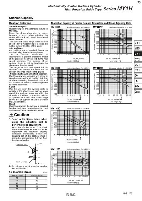
<strong>Mechanically</strong> <strong>Jointed</strong> <strong>Rodless</strong> <strong>Cylinder</strong>High Precision Guide TypeSeries <strong>MY1</strong>H73Cushion CapacityCushion SelectionRubber bumpers are a standard feature on<strong>MY1</strong>H10.Since the stroke absorption of rubberbumpers is short, when adjusting thestroke with an A unit, install an externalshock absorber.The load and speed range which can beabsorbed by a rubber bumper is inside therubber bumper limit line of the graph.Air cushions are a standard feature onmechanically jointed rodless cylinders.The air cushion mechanism isincorporated to prevent excessive impactof the piston at the stroke end during highspeed operation. The purpose of aircushion, thus, is not to decelerate thepiston near the stroke end.The ranges of load and speed that aircushions can absorb are within the aircushion limit lines shown in the graphs.Use this unit when operating with a load orspeed exceeding the air cushion limit line,or when cushioning is required outside ofthe effective air cushion stroke range dueto stroke adjustment.L unitUse this unit when the cylinder stroke isoutside of the effective air cushion rangeeven if the load and speed are within theair cushion limit line, or when the cylinderis operated in a load and speed rangeabove the air cushion limit line or belowthe L unit limit line.H unitUse this unit when the cylinder is operatedin a load and speed range above the L unitlimit line and below the H unit limit line.Caution1. Refer to the figure below whenusing the adjusting bolt toperform stroke adjustment.When the effective stroke of the shockabsorber decreases as a result of strokeadjustment, the absorption capacitydecreases dramatically. Secure theadjusting bolt at the position where itprotrudes approximately 0.5 mm fromthe shock absorber.Adjusting boltShock absorber2. Do not use a shock absorber togetherwith air cushion.Air Cushion Stroke(mm)Bore size (mm)16202532400.5Cushion stroke1215151924Absorption Capacity of Rubber Bumper, Air cushion and Stroke Adjusting Units<strong>MY1</strong>H10 Horizontal collision: P = 0.5 MPa <strong>MY1</strong>H32 Horizontal collision: P = 0.5 MPaCollision speed (mm/s)<strong>MY1</strong>H16Collision speed (mm/s)2000150010005004003002001000.5<strong>MY1</strong>H20Collision speed (mm/s)200015001000500400300200100<strong>MY1</strong>H25Collision speed (mm/s)200015001000500400300200200015001000500400300200Rubber bumperm1, m2, m3maxLoad weight (kg)Horizontal collision: P = 0.5 MPa1 2 3 4 5 10 20 30m1, m2, m3maxLoad weight (kg)Horizontal collision: P = 0.5 MPa1 2 3 4 5 10 20 30 40 50m1, m2, m3maxLoad weight (kg)L unitAir cushionH unitL unitAir cushionHorizontal collision: P = 0.5 MPa100 1 2 3 4 5 10 20 30 40 50m1, m2, m3maxLoad weight (kg)H unit10080 0.05 0.1 0.2 0.3 0.4 0.5 1 2 3 4 5 10H unitL unitAir cushionCollision speed (mm/s)200015001000500400300200100 3 5 10 20 30<strong>MY1</strong>H40Collision speed (mm/s)200015001000500400300200m1, m2, m3maxLoad weight (kg)Horizontal collision: P = 0.5 MPa100 3 5 10 20 30 50 100 200m1, m2, m3maxLoad weight (kg)H unitL unitAir cushion50 100H unitL unitAir cushion8-11-77MXMTSMYCYMGCXD--X20-Data