

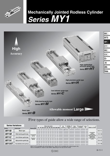
MY1 Mechanically Jointed Rodless Cylinder
MY1 Mechanically Jointed Rodless Cylinder
MY1 Mechanically Jointed Rodless Cylinder
- No tags were found...

Create successful ePaper yourself
Turn your PDF publications into a flip-book with our unique Google optimized e-Paper software.
Series <strong>MY1</strong>Model SelectionFollowing are the steps for selecting the most suitable Series <strong>MY1</strong> to your application.4<strong>Cylinder</strong> modelGuide typeStandards for Tentative Model SelectionStandards for guide selectionGraphs for relatedallowable values<strong>MY1</strong>B<strong>MY1</strong>M<strong>MY1</strong>C<strong>MY1</strong>H<strong>MY1</strong>HTBasic typeSlide bearing guide typeCam follower guide typeHigh precision guide typeHigh rigidity/High precision guide typeGuaranteed accuracy not required, generally combined with separate guideSlide table accuracy approx. ±0.12 mm (2)Slide table accuracy approx. ±0.05 mm (2)Slide table accuracy of ±0.05 mm or less required (2)Slide table accuracy of ±0.05 mm or less required (2) Refer to P. 8-11-12.Refer to P. 8-11-36.Refer to P. 8-11-52.Refer to P. 8-11-68.Refer to P. 8-11-90.Note 1) These accuracy values for each guide should be used only as a guide during selection. Pleasecontact SMC when guaranteed accuracy for <strong>MY1</strong>C/<strong>MY1</strong>H is required.Note 2) “Accuracy” here means displacement of the slide table (at stroke end) when 50% of the allowablemoment shown in the catalog is applied. (reference value).M2: RollingM1: PitchingM3: YawingSelection Flow ChartOperating Conditionsm: Load weight (kg)Mountingorientation:V: Speed (mm/s)Accuracy:P: Operating pressure (MPa)Review the operating conditions.Tentative Selection of <strong>Cylinder</strong> Model<strong>MY1</strong>B : Basic type<strong>MY1</strong>M :Slide bearing guide type<strong>MY1</strong>C : Cam follower guide type<strong>MY1</strong>H : High precision guide type<strong>MY1</strong>HT: High rigidity/high precision guide typeSelect a guide suitablefor the applicationLoad weightm ≤ m maxOKNGSelect larger cylinder size.Change guide type.Determination ofallowable moment[Σα] ≤ 1OKExamination of cushioningmechanism at stroke endNGSelect larger cylinder size.Change guide type.Select larger cylinder size.Air cushionRubber bumperNGType LNGType HNGExternalNGstroke adjusting unitstroke adjusting unitcushioning unit ∗OKOK OK OKExamination of port variations andauto switch mounting (type)Standard type or Centralized piping typeModel selected∗ For external cushioning unit, the installation of a suitable cushioning mechanism near theload center of gravity by the customer's side is recommended.It is possible to select all models of mechanically jointed rodless cylinder (Series <strong>MY1</strong>)according to the step indicated above.Refer to the separate instruction manual for further details. If you have any questions,please contact SMC.8-11-4
Model Selection Series <strong>MY1</strong>5Types of Moment Applied to <strong>Rodless</strong> <strong>Cylinder</strong>sMultiple moments may be generated depending on the mounting orientation, load, and position of the center of gravity.Coordinates and MomentszM3: YawingMXMTSxM2: RollingM1: PitchingyMYCYMGCXStatic MomentHorizontal mountingCeiling mountingWall mountingD--X20-xM2Ym1 x gXM1yxM2YXM1yxM2Zm3 x gXM3zDataVertical mountingzM3Ym4 x gM1Zym2 x gMountingorientationStatic load (m)Static momentM1M2M3Horizontalmountingm1m1 x g x Xm1 x g x Y—Ceilingmountingm2m2 x g x Xm2 x g x Y—Wallmountingm3—m3 x g x Zm3 x g x XVerticalmountingm4 Note)m4 x g x Z—m4 x g x Yg: Gravitational accelerationNote) m4 is a mass movable by thrust. Use 0.3 to 0.7 times thethrust (differs depending on the operating speed) as a guidefor actual use.Dynamic MomentM1M1EFEZυamn x gM3EFEmn x gYυaM3Adjusting boltMountingorientationDynamicload FEM1EM2EHorizontalmountingCeilingmountingWallmounting1.4 υa x δ x mn x g— x FE x ZVerticalmountingDynamic moment M2E is not generated.1M3E— x FE x Y3Note) Regardless of the mounting orientation, dynamicmoment is calculated with the formulae above.13g: Gravitational acceleration, υa: Average speed, δ: Damper coefficient8-11-5
Series <strong>MY1</strong>Model SelectionFollowing are the steps for selecting the most suitable Series <strong>MY1</strong> to your application.61. Operating ConditionsOperating cylinder ···········<strong>MY1</strong>H40-500Average operating speed υa ··· 300 mm/sMounting orientation ···········Wall mountingCushion ································· Air cushion(δ = 1/100)<strong>MY1</strong>H40-500Calculation of Guide Load FactorWb: MGGLB25-200 (4.35 kg)1. HorizontalmountingP. 8-11-36xMounting Orientationzy2. WallmountingxyzWa: Connection plate t = 10 (880 g)2. Load BlockingWc: MHL2-16D1 (795 g)Wd: Workpiece (500 g)3. CeilingmountingP. 8-11-55xzyx4. VerticalmountingP. 8-11-82zFor actual examples of calculation for each orientation,refer to the pages above.y42.55Y111210Z65Y150XWeight and Center of Gravity for Each WorkpieceCenter of gravityWorkpiece no. WeightWn mn X-axis Y-axis Z-axisXn Yn ZnWaWbWcWd0.88 kg4.35 kg0.795 kg0.5 kg65 mm150 mm150 mm150 mm0 mm0 mm111 mm210 mm5 mm42.5 mm42.5 mm42.5 mmn = a, b, c, d3. Composite Center of Gravity Calculationm3 = Σmn= 0.88 + 4.35 + 0.795 + 0.5 = 6.525 kg1X = x ∑(mn x xn)m31= (0.88 x 65 + 4.35 x 150 + 0.795 x 150 + 0.5 x 150) = 138.5 mm6.5251Y = x ∑(mn x yn)m31= (0.88 x 0 + 4.35 x 0 + 0.795 x 111 + 0.5 x 210) = 29.6 mm6.5251Z = x ∑(mn x zn)m31= (0.88 x 5 + 4.35 x 42.5 + 0.795 x 42.5 + 0.5 x 42.5) = 37.4 mm6.5254. Calculation of Load Factor for Static Loadm3: Weightm3max (from (1) of graph <strong>MY1</strong>H/m3) = 50 (kg) ································································Load factor α1 = m3/m3max = 6.525/50 = 0.13M2: MomentM2max (from (2) of graph <strong>MY1</strong>H/M2) = 50 (N·m) ······························································································M2 = m3 x g x Z = 6.525 x 9.8 x 37.4 x 10 –3 = 2.39 (N·m)Load factor α2 = M2/M2max = 2.39/50 = 0.05m3Zm38-11-6M2
Model Selection Series <strong>MY1</strong>7M3: MomentXM3max (from (3) of graph <strong>MY1</strong>H/M3) = 38.7 (N·m) ······································································MXM3 = m3 x g x X = 6.525 x 9.8 x 138.5 x 10 –3 = 8.86 (N·m)Load factor α3 = M3/M3max = 8.86/38.7 = 0.23m3M3MTSMY5. Calculation of Load Factor for Dynamic MomentCYEquivalent load FE at impact1FE = 1.4υa x δ x m x g = 1.4 x 300 x x 6.525 x 9.8 = 268.6 (N)100M1E: MomentM1Emax (from (4) of graph <strong>MY1</strong>H/M1 where 1.4υa = 420 mm/s) = 35.9 (N·m) ··················11M1E = x FE x Z = x 268.6 x 37.4 x 10 –3 = 3.35 (N·m)33Load factor α4 = M1E/M1Emax = 3.35/35.9 = 0.09M3E: MomentM3Emax (from (5) of graph <strong>MY1</strong>H/M3 where 1.4υa = 420 mm/s) = 27.6 (N·m)·······················11M3E = x FE x Y = x 268.6 x 29.6 x 10 –3 = 2.65 (N·m)33Load factor α5 = M3E/M3Emax = 2.65/27.6 = 0.10M1ZM1EFEM3EFEM3YMGCXD--X20-Data6. Sum and Examination of Guide Load Factors∑α = α1 + α2 + α3 + α4 x α5 = 0.60 ≤ 1The above calculation is within the allowable value, and therefore the selected model can be used.Select a shock absorber separately.In an actual calculation, when the sum of guide load factors ∑α in the formula above is more than 1, considerdecreasing the speed, increasing the bore size, or changing the product series.This calculation can be easily made using the “SMC Pneumatics CAD System”.Load WeightAllowable Moment<strong>MY1</strong>H/m3Load weight (kg)5040302010543(1)<strong>MY1</strong>H40<strong>MY1</strong>H32<strong>MY1</strong>H25<strong>MY1</strong>H20<strong>MY1</strong>H/M1Moment (N·m)50403020105432(4)<strong>MY1</strong>H40<strong>MY1</strong>H32<strong>MY1</strong>H25<strong>MY1</strong>H20<strong>MY1</strong>H/M2Moment (N·m)504030201054321(2)<strong>MY1</strong>H40<strong>MY1</strong>H32<strong>MY1</strong>H25<strong>MY1</strong>H20<strong>MY1</strong>H16<strong>MY1</strong>H/M3Moment (N·m)50403020105432(3)(5)<strong>MY1</strong>H40<strong>MY1</strong>H32<strong>MY1</strong>H25<strong>MY1</strong>H2021<strong>MY1</strong>H10100 200 300 400500 1000 1500Piston speed (mm/s)<strong>MY1</strong>H1610.50.40.30.2<strong>MY1</strong>H10100 200 300 400500 1000 1500Piston speed (mm/s)<strong>MY1</strong>H160.50.40.30.20.1<strong>MY1</strong>H10100 200 300400 500 1000 1500Piston speed (mm/s)10.50.40.30.2<strong>MY1</strong>H10100 200 300 400500 1000 1500Piston speed (mm/s)<strong>MY1</strong>H168-11-7
Series <strong>MY1</strong>8PrecautionsBe sure to read before handling. For Safety Instructions and Actuator Precautions, refer to pages 8-34-3 to 8-34-6.MountingCaution1. Do not apply strong impacts orexcessive moment to the slidetable (slider).• The slide table (slider) is supported byprecision bearings (<strong>MY1</strong>C, <strong>MY1</strong>H) orresin bearings (<strong>MY1</strong>B, <strong>MY1</strong>M).Therefore, do not apply strongimpacts or excessive moment, etc.,when mounting workpieces.2. Align carefully when connectingto a load having an externalguide mechanism.• <strong>Mechanically</strong> jointed rodless cylinderscan be used with a direct load withinthe allowable range for each type ofguide. Please note that carefulalignment is necessary whenconnecting to a load having anexternal guide mechanism. As thestroke becomes longer, variations inthe center axis become larger.Consider using a connection method(floating mechanism) that is able toabsorb these variations. Furthermore,use the special floating brackets (referto page 8-11-28) which have beenprovided for Series <strong>MY1</strong>B.3. Do not use in an environmentwhere the cylinder is exposedto coolant, cutting oil, waterdrops, adhesive foreign particles,dust, etc. and avoid usewith compressed air containingdrainage and foreign particles.•Foreign matter or liquids on thecylinder , s interior or exterior can washout the lubricating grease, which canlead to deterioration and damage ofdust seal band and seal materials,causing a danger of malfunction.When operating in locations withexposure to water and oil, or in dustylocations, provide protection such as acover to prevent direct contact withthe cylinder, or mount so that the dustseal band surface faces downward,and operate with clean compressedair.Caution1. Do not unnecessarily alter theguide adjustment setting.• The adjustment of the guide is presetand does not require readjustmentunder normal operating conditions.Therefore, do not unnecessarily alterthe guide adjustment setting.However, series other than the <strong>MY1</strong>HSeries can be readjusted and theirbearings can be replaced.To perform these operations, refer tothe bearing replacement proceduregiven in the instruction manual.Caution1. Air leakage•Take precautions under operatingconditions in which negativepressure is increased inside thecylinder by external forces or inertialforces. Air leakage may occur due toseparation of the seal belt.8-11-8
Series <strong>MY1</strong>Specific Product PrecautionsBe sure to read before handling.9CautionCentralized Piping Port Variations• Head cover piping connection can be freely selected to best suit different piping conditions.Applicable bore sizePort variationsMX<strong>MY1</strong>B10<strong>MY1</strong>H10LRMTSMYCYMGLRLRCXD-Note 1)LRLRRLLRLNote 1)R-XNote 1) These ports are not applicable to <strong>MY1</strong>H10.<strong>MY1</strong>B16 to 100<strong>MY1</strong>M16 to 63<strong>MY1</strong>C16 to 63<strong>MY1</strong>H16 to 40LRLRLSlide table operating directionLRRLRLRLR20-DataLRRLNote 2) RRNote 2)LLO-ringLRPiping tubeSlide table operating directionNote 2) For bottom piping, refer to the figure above.<strong>MY1</strong>HT50/63RLLRLRLRLRSlide table operating direction8-11-9
8-11-1010
11<strong>MY1</strong>BSeriesBasic Typeø10, ø16, ø20, ø25, ø32, ø40, ø50, ø63, ø80, ø100Minimizing the unit size (dimensions)and combination with other guides ispossible.MXMTSMYCYMGCXD--X20-DataBearing8-11-11
Series <strong>MY1</strong>BBefore Operation<strong>Mechanically</strong> <strong>Jointed</strong> <strong>Rodless</strong> <strong>Cylinder</strong>Basic TypeSeries <strong>MY1</strong>B12Maximum Allowable Moment/Maximum Load WeightModelBore size Maximum allowable moment (N·m) Maximum load weight (kg)(mm) M1 M2 M3 m1 m2 m3101620250.82.55.0100.10.30.61.20.30.81.53.05.01521291.03.04.25.80.51.73.05.4<strong>MY1</strong>B3220 2.4 6.0 40 8.0 8.84040 4.8 12 53 10.6 14506380100781603156159.31937732348951870831201501416.6243020294260The above values are the maximum allowable values for moment and load. Refer to each graphregarding the maximum allowable moment and maximum allowable load for a particular piston speed.Caution on DesignWe recommend installing an external shock absorber when the cylinder is combined withanother guide (connection with floating bracket, etc.) and the maximum allowable load isexceeded, or when the operating speed is 1000 to 1500 mm/s for bore sizes ø16, ø50, ø63, ø80and ø100.Load weight (kg)m1Moment (N·m)F1L1M1 = F1 x L1F2L2m2M2 = F2 x L2F3L3m3M3 = F3 x L3Maximum Allowable MomentSelect the moment from within the rangeof operating limits shown in the graphs.Note that the maximum allowable loadvalue may sometimes be exceededeven within the operating limits shown inthe graphs. Therefore, also check theallowable load for the selectedconditions.Maximum Load Weight<strong>MY1</strong>B/M1Moment (N·m)5004003002001005040302010543210.50.40.30.20.1100 200 300 400500 1000 1500Piston speed (mm/s)<strong>MY1</strong>B16<strong>MY1</strong>B10<strong>MY1</strong>B100<strong>MY1</strong>B80<strong>MY1</strong>B63<strong>MY1</strong>B50<strong>MY1</strong>B40<strong>MY1</strong>B32<strong>MY1</strong>B25<strong>MY1</strong>B20<strong>MY1</strong>B16<strong>MY1</strong>B/M2Moment (N·m)5040302010543210.50.40.30.20.10.050.04<strong>MY1</strong>B160.030.02<strong>MY1</strong>B16<strong>MY1</strong>B10100 200 300400500 1000 1500Piston speed (mm/s)<strong>MY1</strong>B100<strong>MY1</strong>B80<strong>MY1</strong>B63<strong>MY1</strong>B50<strong>MY1</strong>B40<strong>MY1</strong>B32<strong>MY1</strong>B25<strong>MY1</strong>B20<strong>MY1</strong>B/M3Moment (N·m)2001005040302010543210.50.40.30.2<strong>MY1</strong>B100<strong>MY1</strong>B80<strong>MY1</strong>B63<strong>MY1</strong>B50<strong>MY1</strong>B40<strong>MY1</strong>B32<strong>MY1</strong>B25<strong>MY1</strong>B200.1<strong>MY1</strong>B160.06<strong>MY1</strong>B16<strong>MY1</strong>B10100 200 300400500 1000 1500Piston speed (mm/s)MXMTSMYCYMGCXD--X20-Data1. Maximum allowable load (1), static moment (2), and dynamic moment (3) (at the time of impact withstopper) must be examined for the selection calculations.∗ To evaluate, use υa (average speed) for (1) and (2), and υ (collision speed υ = 1.4 υa) for (3). Calculate mmaxfor (1) from the maximum allowable load graph (m1, m2, m3) and Mmax for (2) and (3) from the maximum allowablemoment graph (M1, M2, M3).Sum of guideload factorsΣα = + + ≤1Load weight [m]Maximum allowable load [mmax]Note 1) Moment caused by the load, etc., with cylinder in resting condition.Note 2) Moment caused by the impact load equivalent at the stroke end (at the time of impact with stopper).Note 3) Depending on the shape of the workpiece, multiple moments may occur. When this happens, the sum of theload factors (Σα) is the total of all such moments.2. Reference formula [Dynamic moment at impact]Use the following formulae to calculate dynamic moment when taking stopper impact intoconsideration.m: Load weight (kg)F: Load (N)FE: Load equivalent to impact (at impact with stopper) (N)υa: Average speed (mm/s)M: Static moment (N·m)Note 4)υ = 1.4υa (mm/s) FE = 1.4υa·δ·m·gNote 5)1∴ME = ·FE· L1 = = 4.57υaδmL,3Static moment [M] (1)Allowable static moment [Mmax]υ: Collision speed (mm/s)L1: Distance to the load , s center of gravity (m)ME:Dynamic moment (N·m)δDynamic moment [ME] (2)Allowable dynamic moment [MEmax]: Damper coefficientWith rubber bumper = 4/100(<strong>MY1</strong>B10, <strong>MY1</strong>H10)With air cushion = 1/100With shock absorber = 1/100g: Gravitational acceleration (9.8 m/s 2 )Note 4) 1.4υaδ is a dimensionless coefficient for calculating impact force.Note 5) Average load coefficient (= 13): This coefficient is for averaging the maximum load moment at the time ofstopper impact according to service life calculations.3. For detaild selection procedures, refer to pages 8-11-14 to 8-11-15.Select the load from within the range oflimits shown in the graphs. Note that themaximum allowable moment value maysometimes be exceeded even within theoperating limits shown in the graphs.Therefore, also check the allowablemoment for the selected conditions.L1υmFEME<strong>MY1</strong>B/m1Load weight (kg)200100504030201054321100 200 300 400 500 1000 1500Piston speed (mm/s)<strong>MY1</strong>B16<strong>MY1</strong>B10<strong>MY1</strong>B100<strong>MY1</strong>B80<strong>MY1</strong>B63<strong>MY1</strong>B50<strong>MY1</strong>B40<strong>MY1</strong>B32<strong>MY1</strong>B25<strong>MY1</strong>B20<strong>MY1</strong>B16<strong>MY1</strong>B/m2Load weight (kg)302010543210.50.40.30.20.1100 200 300400500 1000 1500Piston speed (mm/s)<strong>MY1</strong>B16<strong>MY1</strong>B10<strong>MY1</strong>B100<strong>MY1</strong>B80<strong>MY1</strong>B63<strong>MY1</strong>B50<strong>MY1</strong>B40<strong>MY1</strong>B32<strong>MY1</strong>B25<strong>MY1</strong>B20<strong>MY1</strong>B16<strong>MY1</strong>B/m3Load weight (kg)5040302010543210.50.40.30.20.1 <strong>MY1</strong>B10100 200 300400500 1000 1500Piston speed (mm/s)<strong>MY1</strong>B100<strong>MY1</strong>B80<strong>MY1</strong>B63<strong>MY1</strong>B50<strong>MY1</strong>B40<strong>MY1</strong>B32<strong>MY1</strong>B25<strong>MY1</strong>B20<strong>MY1</strong>B168-11-128-11-13
Series <strong>MY1</strong>BModel SelectionFollowing are the steps for selecting the most suitable Series <strong>MY1</strong>B to your application.131. Operating Conditions<strong>Cylinder</strong> ······································· <strong>MY1</strong>B32-500Average operating speed υa ···· 300 mm/sMounting orientation ··················Horizontal mountingCushion ······································· Air cushion(δ = 1/100)Calculation of Guide Load FactorW: Workpiece (2 kg)1. HorizontalmountingxMounting Orientationzy2. Wallmounting yP. 8-11-6xz<strong>MY1</strong>B32-5003. CeilingmountingP. 8-11-55xzyx4. VerticalmountingzP. 8-11-82y2. Load BlockingFor actual examples of calculation for each orientation,refer to the pages above.YWeight and Center of Gravity for WorkpieceZ20XWorkpieceno.WWeightm2 kgX-axis20 mmCenter of gravityY-axis30 mmZ-axis50 mm50Y303. Calculation of Load Factor for Static Loadm1: Weightm1max (from (1) of graph <strong>MY1</strong>B/m1) = 27 (kg)················································m1Load factor α1 = m1/m1max = 2/27 = 0.07XM1: MomentM1max (from (2) of graph <strong>MY1</strong>B/M1) = 13 (N·m)············································································m1M1 = m1 x g x X = 2 x 9.8 x 20 x 10 –3 = 0.39 (N·m)Load factor α2 = M1/M1max = 0.39/13 = 0.03M1M2: MomentM2max (from (3) of graph <strong>MY1</strong>B/M2) = 1.6 (N·m)·········································································M3 = m1 x g x Y = 2 x 9.8 x 30 x 10 –3 = 0.59 (N·m)m1YLoad factor α3 = M2/M2max = 0.59/1.6 = 0.37M28-11-14
<strong>Mechanically</strong> <strong>Jointed</strong> <strong>Rodless</strong> <strong>Cylinder</strong>Basic TypeSeries <strong>MY1</strong>B144. Calculation of Load Factor for Dynamic MomentEquivalent load FE at impact1FE = 1.4υa x δ x m x g = 1.4 x 300 x x 2 x 9.8 = 82.3 (N)100M1E: MomentM1Emax (from (4) of graph <strong>MY1</strong>B/M1 where 1.4υa = 420 mm/s) = 9.5 (N·m)·················11M1E = x FE x Z = x 82.3 x 50 x 10 –3 = 1.37 (N·m)33Load factor α4 = M1E/M1Emax = 1.37/9.5 = 0.14M3E: MomentM3Emax (from (5) of graph <strong>MY1</strong>B/M3 where 1.4υa = 420 mm/s) = 2.9 (N·m)·················11M3E = x FE x Y = x 82.3 x 30 x 10 –3 = 0.82 (N·m)33Load factor α5 = M3E/M3Emax = 0.82/2.9 = 0.285. Sum and Examination of Guide Load Factors∑α = α1 + α2 + α3 + α4 + α5 = 0.89 ≤ 1The above calculation is within the allowable value, and therefore the selected model can be used.Select a shock absorber separately.In an actual calculation, when the total sum of guide load factors ∑α in the formula above is more than 1, consider eitherdecreasing the speed, increasing the bore size, or changing the product series. This calculation can be easily made usingthe “SMC Pneumatics CAD System”.FEM1EM3FEM3EM1YZMXMTSMYCYMGCXD--X20-DataLoad Weight<strong>MY1</strong>B/m1Load weight (kg)200100504030201054321(1)<strong>MY1</strong>B10100 200 300 400500 1000 1500Piston speed (mm/s)<strong>MY1</strong>B100<strong>MY1</strong>B80<strong>MY1</strong>B63<strong>MY1</strong>B50<strong>MY1</strong>B40<strong>MY1</strong>B32<strong>MY1</strong>B25<strong>MY1</strong>B20<strong>MY1</strong>B16Allowable Moment<strong>MY1</strong>B/M1Moment (N·m)5004003002001005040302010543210.50.40.30.20.1100 200 300 400500 1000 1500Piston speed (mm/s)<strong>MY1</strong>B100<strong>MY1</strong>B80<strong>MY1</strong>B50<strong>MY1</strong>B40<strong>MY1</strong>B32<strong>MY1</strong>B25<strong>MY1</strong>B20<strong>MY1</strong>B16<strong>MY1</strong>B/M2Moment (N·m)405030201054321(2) <strong>MY1</strong>B63(4) (3)(2) (4)<strong>MY1</strong>B100.50.40.30.20.10.050.04<strong>MY1</strong>B160.030.02<strong>MY1</strong>B10100 200 300400 500 1000 1500Piston speed (mm/s)<strong>MY1</strong>B100<strong>MY1</strong>B80<strong>MY1</strong>B63<strong>MY1</strong>B50<strong>MY1</strong>B40<strong>MY1</strong>B32<strong>MY1</strong>B25<strong>MY1</strong>B20<strong>MY1</strong>B/M3Moment (N·m)2001005040302010543210.50.40.30.20.1(5)0.06<strong>MY1</strong>B10100 200 300 400500 1000 1500Piston speed (mm/s)<strong>MY1</strong>B100<strong>MY1</strong>B80<strong>MY1</strong>B63<strong>MY1</strong>B50<strong>MY1</strong>B40<strong>MY1</strong>B32<strong>MY1</strong>B25<strong>MY1</strong>B20<strong>MY1</strong>B168-11-15
<strong>Mechanically</strong> <strong>Jointed</strong> <strong>Rodless</strong> <strong>Cylinder</strong>Basic TypeSeries <strong>MY1</strong>Bø10, ø16, ø20, ø25, ø32, ø40, ø50, ø63, ø80, ø10015How to Order<strong>MY1</strong>B25300Y7BWNilALHALAHLHBore size (mm)10162025324050638010010 mm16 mm20 mm25 mm32 mm40 mm50 mm63 mm80 mm100 mmBasic typeNilGPipingStandard typeCentralized piping typeNote) For ø10, only G isavailable.Stroke adjusting unitOnly the A unit is available for ø16. Stroke adjusting unit is notavailable for ø50, ø63, ø80 and ø100. For detailed informationon stroke adjusting unit specifications, refer to page 8-11-17.Without adjusting unitWith adjusting boltWith low load shock absorber + Adjusting boltWith high load shock absorber + Adjusting boltWith one A unit and one L unitWith one A unit and one H unit eachWith one L unit and one H unit eachStrokeRefer to “Standard Stroke”on page 8-11-17.Shock Absorbers for L and H UnitsBore size(mm)Unit no.L unitH unit10—RB0805NilS20RB0806RB100725RB1007RB1412Number of auto switchesNilSnAuto switch21nNil Without auto switch∗ For the applicable auto switchmodel, refer to the table below.∗ Auto switches are shipped together,(but not assembled).Suffix for stroke adjusting unit Note)Both sidesOne sideNote) “S” is applicable for stroke adjusting units A, Land H.32 40RB1412RB2015Applicable Auto Switch/Refer to page 8-30-1 for further information on auto switches.For ø10, ø16, ø20TypeReedswitchSolidstateswitchSpecial functionDiagnostic indication(2-color indication)ElectricalentryGrommetGrommetIndicatorlightYesYesFor ø25, ø32, ø40, ø50, ø63, ø80, ø100TypeReedswitchSolidstateswitch—Special functionDiagnostic indication(2-color indication)ElectricalentryGrommetGrommetYesYes∗ Lead wire length symbols: 0.5 m·······Nil (Example) A933 m········L (Example) Y59BL5 m········Z (Example) F9NWZWiring (Output)3-wire (NPN equivalent)2-wire3-wire (NPN)3-wire (PNP)2-wire3-wire (NPN)3-wire (PNP)2-wire• There are other applicable auto switches than listed above. For details, refer to page 8-11-101.• For details about auto switches with pre-wire connector, refer to page 8-30-52.8-11-16———IndicatorlightLoad voltage Auto switch model Lead wire length (m) ∗Pre-wire0.5 3 5DC AC Perpendicular In-lineconnector(Nil) (L) (Z)Applicable load— 5 V — A96V A96 — — IC circuit —24 V 12 V 100 V A93V A93 — — — Relay, PLCM9NV M9N 5 V, 12 VIC circuitM9PV M9P Relay12 VM9BV M9B —24 V —PLCF9NWV F9NW 5 V, 12 VIC circuitF9PWV F9PW 12 V F9BWV F9BW —Load voltage Auto switch model Lead wire length (m) ∗Wiring (Output)Pre-wire0.5 3 5Applicable loadDC AC Perpendicular In-lineconnector(Nil) (L) (Z)3-wire (NPN equivalent) — 5 V — — Z76 — — IC circuit —2-wire 24 V 12 V 100 V — Z73 — — Relay, PLC3-wire (NPN)Y69A Y59A 5 V, 12 VIC circuit3-wire (PNP)Y7PV Y7P 2-wire12 VY69B Y59B — Relay24 V —PLC3-wire (NPN)Y7NWV Y7NW 5 V, 12 VIC circuit3-wire (PNP)Y7PWV Y7PW 2-wire12 V Y7BWV Y7BW —∗ Solid state switches marked with “” are produced upon receipt of order.
<strong>Mechanically</strong> <strong>Jointed</strong> <strong>Rodless</strong> <strong>Cylinder</strong>Basic TypeSeries <strong>MY1</strong>B16Stroke Adjusting Unit SpecificationsBore size (mm)Unit symbolConfigurationShock absorber modelFine stroke adjustment range (mm)Stroke adjustment rangeWithadjustingboltShock Absorber SpecificationsModelMax. energy absorption (J)Stroke absorption (mm)Max. collision speed (mm/s)Max. operating frequency(cycle/min)Springforce (N)ExtendedRetractedOperating temperature range (°C)ASpecifications10 1620H A A LRB0805withadjustingboltWithadjustingboltWithadjustingboltBottom portRB0806withadjustingboltHRB0807withadjustingbolt10 16 20 25 32 40 50 63 80 100AWithadjustingbolt25LRB1007withadjustingbolt0 to –5 0 to –5.6 0 to –6 0 to –11.5RB08051.051000801.963.83JIS SymbolHRB1412withadjustingboltPiston Speedø5AWithadjustingbolt32LRB1412withadjustingboltø8Hø10RB2015withadjustingboltRc 3/8AWithadjustingboltø1640LRB1412withadjustingboltWhen exceeding the stroke fine adjustment range: Utilize a made-to-order specifications “-X416” and “-X417”.RB08062.961500801.964.22RB10075.971500704.226.865 to 60Bore size (mm)FluidActionOperating pressure rangeProof pressureAmbient and fluid temperatureCushionLubricationStroke length tolerance0.2 to 0.8 MPaRubber bumper+1.81000 or less 0+2.81001 to 3000 0AirDouble acting0.1 to 0.8 MPa1.2 MPa5 to 60°CAir cushionNon-lubeFront/Side port M5 x 0.8 Rc 1/8 Rc 1/4PipingPort sizeRB141219.6121500456.8615.98RB201558.8151500258.3420.50Bore size (mm)Without stroke adjusting unitStrokeadjusting unitø4+1.8+2.82700 or less 0 , 2701 to 5000 0ø6A unitL unit and H unitø110 to –12 0 to –16Rc 1/2ø18HRB2015withadjustingbolt1016 to 100100 to 500 mm/s 100 to 1000 mm/s100 to 200 mm/s 100 to 1000 mm/s (1)100 to 1000 mm/s 100 to 1500 mm/s (2)Note 1) Be aware that when the stroke adjusting range is increased bymanipulating the adjusting bolt, the air cushion capacitydecreases. Also, when exceeding the air cushion stroke rangeson page 8-11-20, the piston speed should be 100 to 200 mm persecond.Note 2) The piston speed is 100 to 1000 mm/s for centralized piping.Note 3) Use at a speed within the absorption capacity range. Refer topage 8-11-19.MXMTSMYCYMGCXD--X20-DataSymbol-XB11-XC18-XC67-X168-X416-X417Made to Order Specifications(For details, refer to page 8-31-1.)SpecificationsLong stroke typeNPT finish piping portNBR rubber lining in dust seal bandHelical insert thread specificationsHolder mounting bracket ΙHolder mounting bracket ΙΙStandard StrokeBore size(mm)10, 1620, 25, 32, 4050, 63, 80, 100Standard stroke (mm) ∗100, 200, 300, 400, 500, 600, 700800, 900, 1000, 1200, 1400, 16001800, 2000Maximum manufacturable stroke(mm)∗ Strokes are manufacturable in 1 mm increments, up to the maximum stroke. However, whenexceeding a 2000 mm stroke, specify “-XB11” at the end of the model number.300050008-11-17
Series <strong>MY1</strong>B17Theoretical OutputBoresize(mm)101620253240506380100(N)Piston Operating pressure (MPa)area(mm 2 ) 0.2 0.3 0.4 0.5 0.6 0.7 0.878 15 23 31 39 46 54 62200 40 60 80 100 120 140 160314 62 94 125 157 188 219 251490 98 147 196 245 294 343 392804 161 241 322 402 483 563 6431256 251 377 502 628 754 879 10051962 392 588 784 981 1177 1373 15693115 623 934 1246 1557 1869 2180 24925024 1004 1507 2009 2512 3014 3516 40197850 1570 2355 3140 3925 4710 5495 6280Note) Theoretical output (N) = Pressure (MPa) xPiston area (mm 2 )WeightBore size(mm)AdditionalBasic weightweight per each 50mmof strokeSide supportweight (per set)Type A and BA unitweightStroke adjusting unit weight(per unit)L unitweight1016202532405063801000.150.611.061.332.653.877.7813.1020.7035.700.040.060.100.120.180.270.440.701.181.970.0030.010.020.020.020.040.040.080.170.170.010.040.050.060.120.23——————0.050.100.210.32————Calculation: (Example) <strong>MY1</strong>B25-300A• Basic weight ······························ 1.33 kg• <strong>Cylinder</strong> stroke ·························· 300 stroke• Additional weight ······················· 0.12/50 stroke1.33 + 0.12 x 300/50 + 0.06 x 2 ≅ 2.17 kg• Weight of A unit ························· 0.06 kgH unitweight0.02—0.100.180.400.49————(kg)OptionStroke Adjusting Unit Part No.Bore size(mm)Unit no.A unitL unitH unit10MY-A10A—MY-A10H16MY-A16A——20MY-A20AMY-A20LMY-A20H25MY-A25AMY-A25LMY-A25H32MY-A32AMY-A32LMY-A32HBore size(mm)Unit no.Side Support Part No.TypeA unitL unitH unitBore size(mm)Side support ASide support B40MY-A40AMY-A40LMY-A40H10MY-S10AMY-S10B16MY-S16AMY-S16B20MY-S20AMY-S20B25MY-S25AMY-S25B32TypeBore size(mm)Side support ASide support B40 50 63MY-S32AMY-S32BMY-S50AMY-S50BFor details about dimensions, etc., refer to page 8-11-27.80MY-S63AMY-S63B1008-11-18
<strong>Mechanically</strong> <strong>Jointed</strong> <strong>Rodless</strong> <strong>Cylinder</strong>Basic TypeSeries <strong>MY1</strong>B18Cushion CapacityCushion SelectionRubber bumpers are a standard feature on<strong>MY1</strong>B10.Since the stroke absorption of rubber bumpersis short, when adjusting the stroke withan A unit, install an external shock absorber.The load and speed range which can beabsorbed by a rubber bumper is inside therubber bumper limit line of the graph.Air cushions are a standard feature onmechanically jointed rodless cylinders.(Except ø10.)The air cushion mechanism is incorporatedto prevent excessive impact of the pistonat the stroke end during high speedoperation. The purpose of air cushion,thus, is not to decelerate the pistonnear the stroke end.The ranges of load and speed that aircushions can absorb are within the aircushion limit lines shown in the graphs.Use this unit when operating with a load orspeed exceeding the air cushion limit line,or when cushioning is required outside ofthe effective air cushion stroke range dueto stroke adjustment.L unitUse this unit when cushioning is necessaryoutside of the effective air cushionrange even if the load and speed are withinthe air cushion limit line, or when the cylinderis operated in a load and speedrange above the air cushion limit line andbelow the L unit limit line.H unitUse this unit when the cylinder is operatedin a load and speed range above the L unitlimit line and below the H unit limit line.Caution1. Refer to the figure below whenusing the adjusting bolt to performstroke adjustment.When the effective stroke of the shockabsorber decreases as a result ofstroke adjustment, the absorption capacitydecreases dramatically. Securethe adjusting bolt at the position whereit protrudes approximately 0.5 mm fromthe shock absorber.Adjusting bolt0.5Absorption Capacity of Rubber Bumper, Air Cushion and Stroke Adjusting Units<strong>MY1</strong>B10Collision speed (mm/s) Collision speed (mm/s)<strong>MY1</strong>B20Collision speed (mm/s)200015001000500400300200100<strong>MY1</strong>B25Collision speed (mm/s)200015001000500400300200200015001000500400300200Horizontal collision: P = 0.5 MPa100800.05 0.1 0.2 0.3 0.4 0.5 1 2 3 4 5 10m3max m2max m1maxLoad weight (kg)Horizontal collision: P = 0.5 MPa2000150010005004003002001000.5<strong>MY1</strong>B161 2 3 4 5 10 20 30m3maxRubber bumperAir cushionm2maxLoad weight (kg)Horizontal collision: P = 0.5 MPa1 2 3 4 5 10 20 30 40 50m3max m2maxLoad weight (kg)H unitL unitAir cushionm1maxHorizontal collision: P = 0.5 MPaL unitAir cushionH unitm1maxH unit<strong>MY1</strong>B32Collision speed (mm/s)200015001000500400300200100 1 2 3 4 5 10 20 30 40 50m3maxm2maxm1maxLoad weight (kg)<strong>MY1</strong>B40Collision speed (mm/s)200015001000500400300200Horizontal collision: P = 0.5 MPaHorizontal collision: P = 0.5 MPa100 2 3 4 5 10 20 50<strong>MY1</strong>B50Collision speed (mm/s)Collision speed (mm/s)200015001000500400300200m2max m3maxLoad weight (kg)100 2 3 5 10 20 30 50<strong>MY1</strong>B63200015001000500400300200Air cushionm2max m3maxLoad weight (kg)H unitL unitH unitL unitAir cushionm1maxHorizontal collision: P = 0.5 MPaAir cushion100m1maxHorizontal collision: P = 0.5 MPaAir cushionMXMTSMYCYMGCXD--X20-DataShock absorber2. Do not use a shock absorber togetherwith air cushion.1001 2 3 4 5 10 20 30 40 50m2, m3max m1maxLoad weight (kg)100 2 3 5 10 20 30 50 100m2max m3max m1maxLoad weight (kg)8-11-19
Series <strong>MY1</strong>B19Cushion CapacityRubber Bumper/Air CushionStroke Adjustment Unit AbsorptionCapacity<strong>MY1</strong>B80Collision speed (mm/s)200015001000<strong>MY1</strong>B100Collision speed (mm/s)200015001000Displacement (mm)500400300200100 5 10 20 30 50 100500400300200Horizontal collision: P = 0.5 MPam2max m3max m1maxLoad weight (kg)Horizontal collision: P = 0.5 MPa100 5 10 20 30 50 100m2max m3max m1maxLoad weight (kg)Air Cushion StrokeBore size (mm)162025324050638010010.90.80.70.60.50.40.30.20.1Air cushionAir cushionCushion stroke121515192430374040Rubber Bumper (ø10 only)Positive Stroke from One EndDue to Pressure00 0.1 0.2 0.3 0.4 0.5 0.6 0.7 0.8Pressure (MPa)8-11-20Tightening Torque for StrokeAdjusting Unit Holding Bolts(N·m)Bore size (mm)101620253240UnitAHAALHALHALHALHTightening torqueTightening Torque for Stroke AdjustingUnit Lock Plate Holding Bolts (N·m)Bore size (mm)20253240UnitHLHLHLHTightening torque1.21.23.33.3103.310Calculation of Absorbed Energyfor Stroke Adjusting Unitwith Shock Absorber(N·m)Type ofimpactKinetic energyE1Thrust energyE2Absorbed energyEHorizontalcollisionυ msVertical(Downward)12υ mm·υ 2Vertical(Upward)F·s Fs + m·g·s Fs – m·g·sE1 + E2s0.30.61.53.05.0sυ mSymbolυ: Speed of impact object (m/s)F: <strong>Cylinder</strong> thrust (N)s: Shock absorber stroke (m)m:Weight of impact object (kg)g: Gravitational acceleration (9.8 m/s 2 )Note) The speed of the impact object is measured atthe time of impact with the shock absorber.10PrecautionsBe sure to read before handling.For Safety Instructions andActuator Precautions, refer topages 8-34-3 to 8-34-6.CautionUse caution not to get your handscaught in the unit.• When using a product with strokeadjusting unit, the space between theslide table (slider) and the strokeadjusting unit becomes narrow at thestroke end, causing a danger of handsgetting caught. Install a protective coverto prevent direct contact with the humanbody.Adjusting boltlock nutLock plateThe unit can be secured by evenlytightening the four unit holding bolts.CautionUnit holding boltLock plateholding boltShock absorberDo not operate with the strokeadjusting unit fixed in anintermediate position.When the stroke adjusting unit is fixed inan intermediate position, slippage canoccur depending on the amount of energyreleased at the time of an impact. In suchcases, the use of the adjusting boltmounting brackets, available per made-toorderspecifications -X416 and -X417, isrecommended. (Except ø10)For other lengths, please consult withSMC (Refer to “Tightening Torque forStroke Adjusting Unit Holding Bolts”.)Loosen the adjusting bolt lock nut, andadjust the stroke from the lock plate sideusing a hexagon wrench. Retighten thelock nut.Loosen the two lock plate holding bolts,turn the shock absorber and adjust thestroke. Then, uniformly tighten the lockplate holding bolts to secure the shockabsorber.Take care not to over-tighten the holdingbolts. (Except ø10 and ø20 L unit.) (Referto “Tightening Torque for Stroke AdjustingUnit Lock Plate Holding Bolts”.)Note)Although the lock plate may slightly benddue to tightening of the lock plate holdingbolt, this does not a affect the shockabsorber and locking function.
<strong>Mechanically</strong> <strong>Jointed</strong> <strong>Rodless</strong> <strong>Cylinder</strong>Basic TypeSeries <strong>MY1</strong>B20Centralized Piping Type ø10Refer to page 8-11-9 regarding centralized piping port variations.<strong>MY1</strong>B10GStrokeMX7.310107.8MTSMYCY2-M5 x 0.8(Hexagon socket head plug)MGCX30 505.9 254-M3 x 0.5 depth 5265.92 x 2-ø3.4 through-holeBottom side M4 x 0.7 depth 7D--X20-172228Data5100 + StrokeSMC1.72-ø5 counterbore depth 21103253.5Floating bracket mounting thread(2-M3 x 0.5 thread depth 5)2-M5 x 0.8(Port)311020.22.224SMC19.5277.312 8.52-M5 x 0.8(Hexagon socket head plug)101555110 + Stroke10156.88.5 122-M5 x 0.8(Hexagon socket head plug)8-11-21
Series <strong>MY1</strong>B21Standard Type/Centralized Piping Type ø16, ø20Refer to page 8-11-9 regarding centralized piping port variations.<strong>MY1</strong>B16/20Stroke(LL)LPA4-MM depth M2 x 2-øB counterbore depth CøLD through-holeQ + StrokeM5 x 0.8(Hexagon socket head plug)PC2-øT counterbore depth EFloating bracket mounting thread(2-JJ thread depth from bottom of counter bore KK)M5 x 0.8(Port)1UUTTRR SS2-M5 x 0.8(Hexagon socket head plug)M5 x 0.8(Hexagon socket head plug)QQGGAM5 x 0.8(Port)ACushion needleM5 x 0.8(Hexagon socket head plug)Z + StrokeYH2 x 2-J depth KGAGGBNNENHRR SSTT2-M5 x 0.8(Hexagon socket head plug)M5 x 0.8(Port)UUM5 x 0.8(Hexagon socket head plug)XX (WW)XX (WW)M5 x 0.8(Port)Model<strong>MY1</strong>B16<strong>MY1</strong>B20<strong>MY1</strong>BGVV2-M5 x 0.8 2-M5 x 0.8(Hexagon socket head plug) (Hexagon socket head plug)<strong>MY1</strong>BGA B C E G GA GB H J JJ K KK L LD LL LW M MM N NC80 6 3.5 2 14 9 16 37 M5 x 0.8 M4 x 0.7 10 6.5 80 3.5 40 30 6 M4 x 0.7 20 14100 7.5 4.5 2 12.5 12.5 17.5 46 M6 x 1 M4 x 0.7 12 10 100 4.5 50 37 8 M5 x 0.8 25 17.5VV(mm)NE27.834Model<strong>MY1</strong>B16<strong>MY1</strong>B20NH2733.5NW3745PA PB PC PD PG PP Q QQ QW RR SS T TT UU VV WW40 20 40 4.5 3.5 7.5 153 9 30 11 3 7 9 10.5 10 7.550 25 50 5 4.5 11.5 191 11 36 14.5 5 8 10.5 12 12.5 10.5XX2224YH2632.5YW3240Z1602002-ødYSRPBQWNWYWPGPDLWPPNCPP QQH(mm)XXøDBottom ported(Applicable O-ring)8-11-22Hole Size for Centralized Piping on the BottomModel WX Y S d D R Applicable O-ring<strong>MY1</strong>B16 22 6.5 4 4 8.4 1.1C6<strong>MY1</strong>B20 24 8 6 4 8.4 1.1(Machine the mounting side to the dimensions below.)
<strong>Mechanically</strong> <strong>Jointed</strong> <strong>Rodless</strong> <strong>Cylinder</strong>Basic TypeSeries <strong>MY1</strong>B22Standard Type/Centralized Piping Type ø25, ø32, ø40Refer to page 8-11-9 regarding centralized piping port variations.<strong>MY1</strong>B25/32/40Stroke(LL)L4-MM depth MPA2 x 2-øB counterbore depth CøLD through-holePBQWNWPGQ + StrokeP(Hexagon socket head taper plug)RR SSUU TT2-P(Hexagon socket head taper plug)P(Hexagon socket headtaper plug)PP QQG2-øT counterbore depth EP(Port)AFloating bracket mounting thread(2-JJ thread depth from bottom of counter bore KK)Z + StrokeP(Port)Cushion needleP(Hexagon socket head taper plug)2 x 2-J depth KGGBN(WW)PP QQHNENHRR SSTT2-P(Hexagon socket head taper plug)P(Port)UUP(Hexagon socket headtaper plug)XXXXP(Port)VV2-ZZ(Hexagon socket head taper plug)2-ZZ(Hexagon socket head taper plug)Model A B C E G GB H J JJ K KK L LD LL LW M MM N NC NE<strong>MY1</strong>B25 110 9 5.5 2 16 24.5 54 M6 x 1 M5 x 0.8 9.5 9 110 5.6 55 42 9 M5 x 0.8 30 20 40.5<strong>MY1</strong>B32 140 11 6.6 2 19 30 68 M8 x 1.25 M5 x 0.8 16 10 140 6.8 70 52 12 M6 x 1 37 25 50<strong>MY1</strong>B40 170 14 8.5 2 23 36.5 84 M10 x 1.5 M6 x 1 15 13 170 8.6 85 64 12 M6 x 1 45 30.5 63VVNH394961.5(mm)NW536475Model P PA PB PC PD PP Q QQ QW RR SS T TT UU VV WW XX YH YW Z<strong>MY1</strong>B25 Rc 1/8 60 30 55 6 12 206 16 42 16 6 10 14.5 15 16 12.5 28 38.5 46 220<strong>MY1</strong>B32 Rc 1/8 80 35 70 10 17 264 16 51 23 4 10 16 16 19 16 32 48 55 280<strong>MY1</strong>B40 Rc 1/4 100 40 85 12 18.5 322 24 59 27 10.5 14 20 22 23 19.5 36 60.5 67 340“P” indicates cylinder supply ports.2-ød Y(mm)ZZRc 1/16Rc 1/16Rc 1/8SRYWMXMTS(WW)PCPDYH1NCLWMYCYMGCXD--X20-Data<strong>MY1</strong>BG<strong>MY1</strong>BGWXøDBottom ported (ZZ)(Applicable O-ring)Hole Size for Centralized Piping on the BottomModel<strong>MY1</strong>B25<strong>MY1</strong>B32WX Y S d D R Applicable O-ring28 9 7 6 11.4 1.1C932 11 9.5 6 11.4 1.1<strong>MY1</strong>B40 36 14 11.5 8 13.4 1.1 C11.2(Machine the mounting side to the dimensions below.)8-11-23
Series <strong>MY1</strong>B23Standard Type/Centralized Piping Type ø50, ø63Refer to page 8-11-9 regarding centralized piping port variations.<strong>MY1</strong>B50/63Stroke(LL)L4-MM depth MPA2 x 2-øB counterbore depth CøLD through-holeUURc 3/8(Hexagon socket head taper plug)TTRR SS2-Rc 3/8(Hexagon socket head taper plug)Rc 3/8(Hexagon socket headtaper plug)Rc 3/8(Hexagon socket headtaper plug)QQPP(WW)XXVVPC2-øT counterbore depth EGRc 3/8(Port)APDFloating bracket mounting thread(2-JJ thread depth from bottom of counter bore KK)Z + Stroke2-Rc 1/4(Hexagon socket head taper plug)YHCushion needleRc 3/8(Port)Rc 3/8(Hexagon socket head taper plug)2 x 2-J depth K2-Rc 1/4(Hexagon socket head taper plug)NGGB1VVNCPP QQXX (WW)HQWNWNEYWPGQ + StrokeNHSSRRTT2-Rc 3/8(Hexagon socket head taper plug)Rc 3/8(Port)Rc 3/8(Port)LWUUModel<strong>MY1</strong>B50<strong>MY1</strong>B63A B C E G GB H J JJ K KK L LD LL LW M MM N NC200 14 8.5 3 23.5 37 94 M12 x 1.75 M6 x 1 25 17 200 9 100 80 14 M8 x 1.25 47 38230 17 10.5 3 25 39 116 M14 x 2 M8 x 1.25 28 24 230 11 115 96 16 M8 x 1.25 50 51NE76.5100ModelNHNWPA PB PC PD PG PP QQQ QW RR SS T TT UU VV WWXXYHYWZ<strong>MY1</strong>B507592120 50 100 8.5 8 24 384 27 76 34 10 15 22.5 23.5 23.5 22.5477492400<strong>MY1</strong>B6395112140 60 115 9.5 10 37.5 440 29.5 92 44.5 13.5 16 27 29 25 2856941124602-ødYSRPB<strong>MY1</strong>BG<strong>MY1</strong>BG(mm)(mm)WXøDBottom ported(Applicable O-ring)Hole Size for Centralized Piping on the BottomModel WX Y S d D R Applicable O-ring<strong>MY1</strong>B50 47 15.5 14.5 10 17.5 1.1C15<strong>MY1</strong>B63 56 15 18 10 17.5 1.1(Machine the mounting side to the dimensions below.)8-11-24
<strong>Mechanically</strong> <strong>Jointed</strong> <strong>Rodless</strong> <strong>Cylinder</strong>Basic TypeSeries <strong>MY1</strong>B24Standard Type/Centralized Piping Type ø80, ø100Refer to page 8-11-9 regarding centralized piping port variations.<strong>MY1</strong>B80/100Stroke(LL)PFLPEPA4-MM depth MYW2 x 2-øLD through-holePBQWNWMXUURc 1/2(Hexagon socket headtaper plug)TTRR SS2-Rc 1/2(Hexagon socket head taper plug)Rc 1/2(Hexagon socket headtaper plug)PP QQ(WW)PGG±0.0580Floating bracket mounting thread(2-ø10H7 depth 10)Q + StrokeRc 1/2(Port)Rc 1/2Cushion needle(Port) Rc 1/2A(Hexagon socket head taper plug)Z + StrokeYHGGBN1NNYY(WW)NCQQPPHNHSSRR2-Rc 1/2(Hexagon socket head taper plug)Rc 1/2(Port)TTLWUUMTSMYCYMGCXD--X20-DataRc 1/2(Hexagon socket headtaper plug)XXVV2-Rc 1/2(Hexagon socket head taper plug)2-Rc 1/2(Hexagon socket head taper plug)VVXXRc 1/2(Port)<strong>MY1</strong>BG<strong>MY1</strong>BG(mm)Model<strong>MY1</strong>B80<strong>MY1</strong>B100A G GB H L LD LL LW M MM N NC NH NN NW345 60 71.5 150 340 14 175 112 20 M10 x 1.5 85 65 124 35 140400 70 79.5 190 400 18 200 140 25 M12 x 1.75 95 85 157 45 176PA PB80 65120 85PE240280(mm)Model<strong>MY1</strong>B80<strong>MY1</strong>B100PF2242PG1520PP5369Q660760QQ QW RR SS TT UU VV WW XX YH YW YY35 90 61 15 30 40 60 25 90 122 140 2838 120 75 20 40 48 70 28 120 155 176 35Z6908002-ødYRWXøDBottom ported(Applicable O-ring)Hole Size for Centralized Piping on the BottomModel WX Y d D R Applicable O-ring<strong>MY1</strong>B80 90 45 18 26 1.8P22<strong>MY1</strong>B100 120 50 18 26 1.8(Machine the mounting side to the dimensions below.)8-11-25
Series <strong>MY1</strong>B25Stroke Adjusting UnitWith adjusting bolt<strong>MY1</strong>B Bore size Stroke AEEAEBWStroke adjusting unithTTFCTTh15.42.8TThECEY(mm)Applicable bore size E EA EB EC EY FC h TT W<strong>MY1</strong>B10 10 5 28 3.3 26.3 — 1.8 5 (Max. 10) 35<strong>MY1</strong>B16 14.6 7 34.4 4.2 36.5 — 2.4 5.4 (Max. 11) 43<strong>MY1</strong>B20<strong>MY1</strong>B25<strong>MY1</strong>B32<strong>MY1</strong>B40192025319101215434961765.86.58.59.545.653.56781.5131317173.23.54.54.56 (Max. 12)5 (Max. 16.5)8 (Max. 20)9 (Max. 25)53607494With low load shock absorber+ Adjusting bolt<strong>MY1</strong>B Bore size Stroke LTThEFEA<strong>MY1</strong>B10<strong>MY1</strong>B16EBWStroke adjusting unit(Shock absorber stroke) TSShock absorberFWFBFCECEYFHApplicable bore size<strong>MY1</strong>B20<strong>MY1</strong>B25<strong>MY1</strong>B32<strong>MY1</strong>B40E EA EB EC EY F FB FC FH FW h S T TT19 9 43 5.8 45.6 4 — 13 — — 3.2 40.8 6 6 (Max. 12)20 10 49 6.5 53.5 6 33 13 12 46 3.5 46.7 7 5 (Max. 16.5)25 12 61 8.5 67 6 43 17 16 56 4.5 67.3 12 8 (Max. 20)31 15 76 9.5 81.5 6 43 17 16 56 4.5 67.3 12 9 (Max. 25)With high load shock absorber+ Adjusting bolt<strong>MY1</strong>B Bore size Stroke HTThEFEATTW53607494(mm)Shock absorber modelRB0806RB1007RB1412RB1412EBWStroke adjusting unit(Shock absorber stroke) TWorkpieceSFWFBFCECEYFHhaShock absorber15.42.8∗ Since the dimension EY of H unit is greater than thetable top height (dimension H), when a workpiece isloaded that is larger than the full length (dimension L) of the slidetable allow a clearance of size “a” or larger at the workpiece side.<strong>MY1</strong>B10Applicable bore size E EA EB EC EY F FB FC FH FW h S T TT W Shock absorber model a<strong>MY1</strong>B10 10 5 28 5.5 29.8 — — 8 — — 1.8 40.8 5 5 (Max. 10) 35 RB0805 3.5<strong>MY1</strong>B20 20 10 49 6.5 47.5 6 33 13 12 46 3.5 46.7 7 5 (Max. 11) 60 RB1007 2.5<strong>MY1</strong>B25<strong>MY1</strong>B32<strong>MY1</strong>B402025311012155774828.511.51257.573876884357571722221622225674744.55.55.567.373.273.21215155 (Max. 16.5)8 (Max. 20)9 (Max. 25)7090100RB1412RB2015RB20154.5648-11-26(mm)
<strong>Mechanically</strong> <strong>Jointed</strong> <strong>Rodless</strong> <strong>Cylinder</strong>Basic TypeSeries <strong>MY1</strong>B26Side SupportSide support AMY-SA2-øGSide support BMY-SBCD2-øHABFEMXMTSMY2-JCYMGCDABModelAMY-S10 BAMY-S16 BAMY-S20 BApplicable bore size<strong>MY1</strong>B10<strong>MY1</strong>B16<strong>MY1</strong>B20A354353B43.653.665.6C121525A <strong>MY1</strong>B25 61 75MY-S25 B<strong>MY1</strong>B32 70 84A <strong>MY1</strong>B40 87 105MY-S32 B<strong>MY1</strong>B50 113 1313545AMY-S50 B <strong>MY1</strong>B63 136 158 55A <strong>MY1</strong>B80 170 200MY-S63 B<strong>MY1</strong>B100 206 23670ED21263850E3.64.96.48F1.8345G6.56.589.5H3.43.44.55.5JM4 x 0.7M4 x 0.7M5 x 0.8M6 x 1648010011.714.818.368.510.5111417.56.6911.5(mm)M8 x 1.25M10 x 1.5M12 x 1.75CXD--X20-DataGuide for Side Support ApplicationFor long stroke operation, the cylinder tubemay be deflected depending on its own weightand the load weight. In such a case, use a sidesupport in the middle section. The spacing (l)of the support must be no more than thevalues shown in the graph on the right.ml(kg) 200190180170160150(4000)140Caution1. If the cylinder mounting surfaces arenot measured accurately, using a sidesupport may cause poor operation.Therefore, be sure to level the cylindertube when mounting. Also, for longstroke operation involving vibrationand impact, use of a side support isrecommended even if the spacingvalue is within the allowable limitsshown in the graph.2. Support brackets are not for mounting;use them solely for providing support.lmmllWeight (m)1301201101009080706050403020100(400)(1800)(1500)(1200)(1100)(900)<strong>MY1</strong>B20<strong>MY1</strong>B16<strong>MY1</strong>B10<strong>MY1</strong>B25(3200)(2700)(2100)<strong>MY1</strong>B32<strong>MY1</strong>B40<strong>MY1</strong>B50<strong>MY1</strong>B63<strong>MY1</strong>B801000 2000 3000 4000 5000Support spacing (l )(mm)<strong>MY1</strong>B1008-11-27
Series <strong>MY1</strong>B27Floating BracketFacilitates connection to other guide systems.Applicable bore sizeApplication ExampleApplicable bore sizeø16, ø20Application ExampleWorkpieceWWMounting ExampleGuideMounting ExampleSeries <strong>MY1</strong>BFloatingbracket3020Za1GDZa1220.556M4 x 0.7Zb8.54153111Section Za detail (3/1)Adjustable rangeCAPQKLJJ2 x 2-øLDHZbBFE4 E4E3 E3Section Za detail(Adjustable range)28.53.5Section Zb detail (3/1)Adjustable rangeSection Zb detail(Adjustable range)2 x 2-ø6.5ModelMY-J16MY-J20Applicable bore size<strong>MY1</strong>B16<strong>MY1</strong>B20A4555B4552C22.526D3035F5259G3850(mm)H1821ModelMY-J16MY-J20Applicable bore size<strong>MY1</strong>B16<strong>MY1</strong>B20JJM4 x 0.7M4 x 0.7K1010L44P77Q3.53.5E311E411LD66Installation of Holding BoltsSlider(Piston yoke)Pin Conical spring washer Holding boltTightening Torque for Holding BoltsModelMY-J10MY-J16MY-J20Tightening torque0.61.51.5ModelMY-J25MY-J32MY-J40Tightening torque355ModelMY-J50MY-J63(N·m)Tightening torque5138-11-28
<strong>Mechanically</strong> <strong>Jointed</strong> <strong>Rodless</strong> <strong>Cylinder</strong>Basic TypeSeries <strong>MY1</strong>B28Applicable bore sizeApplicable bore sizeø25, ø32, ø40 ø50, ø63Application ExampleApplication ExampleWorkpieceWorkpieceWWMXMTSMYCY4-øMMGDGuide Series <strong>MY1</strong>B FloatingBracketMounting ExampleOne set of brackets can be mounted in two directions forcompact combinations.ZFBE2E2E1E1Section Z detail(Adjustable range)B2C1FB3B1CAGuideMounting ExamplePQKLGDSeries <strong>MY1</strong>BJJH2 x 2-øLDZaZbFloatingbracketBFE4 E4E3 E3Section Za detail(Adjustable range)MGCXD--X20-DataAHModelMY-J25MY-J32MY-J40CApplicablebore size<strong>MY1</strong>B25<strong>MY1</strong>B32<strong>MY1</strong>B40JMounting direction (1) Mounting direction (2)D405574holding boltCommonG H J60801003.24.54.5354047MM5.56.56.5C2HA(mm)Mounting direction (2)A637692B7894112C394756F100124144ModelMY-J50MY-J63ModelMY-J50MY-J63Applicable bore size<strong>MY1</strong>B50<strong>MY1</strong>B63Applicable bore size<strong>MY1</strong>B50<strong>MY1</strong>B63A110131JJM8 x 1.25M10 x 1.5B110130K2020C5565L7.59.5D7080P1619F126149Q89.5Section Zb detail(Adjustable range)E32.52.5G90100E42.52.5(mm)H3737LD1114ModelMY-J25MY-J32MY-J40Applicablebore size<strong>MY1</strong>B25<strong>MY1</strong>B32<strong>MY1</strong>B40A658298B1284044Mounting direction (1)B2536476B37888108C1142022C2394454Adjustable rangeF E1 E296 1 1111 1 1131 1 1Note) One set of floating brackets consists of one right piece and one leftpiece.8-11-29
Series <strong>MY1</strong>B29Floating BracketFacilitates connection to other guide systems.Applicable bore sizeø80, ø100Application ExampleMounting bracketGuideWWorkpieceBracketSlider(Piston yoke)Floating Bracket Operating PrecautionsCautionMake sure that the amount of divergence from theexternal guide is within the adjustable range.Using the floating bracket facilitates connection to an externalguide. However, with a rod type guide, etc., the amount ofdisplacement is large and the floating bracket may not be able toabsorb the variation. Check the amount of displacement andmount the floating bracket within the adjustable range.When the displacement amount exceeds the adjustable range,use a separate floating mechanism.Mounting ExampleSupport bracket mounting area is heat treated at HRC40 or above.Floating with flat bar Floating with round barBracket150+0.320 +0.1+0.3112Floating BracketPositioning hole(ø10 x 18l ) Bracket mounting hole (ø80)Hexagon socket head cap screw (M10 x 1.5 x 40l)Mounting bracketBracket mounting hole (ø100)Hexagon socket head cap screw (M12 x 1.75 x 40l)A3118CBModelMY-J 80MY-J100Applicable bore size<strong>MY1</strong>B80<strong>MY1</strong>B100A181221B (max)1515C (min)99Hexagon SocketHead Cap ScrewTighteningTorqueModelMY-J80MY-J100(N·m)Tightening torque2544Note) • Flat bar or round bar mounting are possible for the support bracket(slanted lines) mounted by the customer.• The floating bracket is shipped together with (4) hexagon socket headcap screws and (2) parallel pins at the time of shipment.• “B” and “C” indicate the allowable mounting dimensions for the supportbracket (flat bar or round bar).• Consider support brackets with dimensions that allow the floatingmechanism to function properly.8-11-30
<strong>Mechanically</strong> <strong>Jointed</strong> <strong>Rodless</strong> <strong>Cylinder</strong>Basic TypeSeries <strong>MY1</strong>B30Construction: ø10Centralized piping type: <strong>MY1</strong>B10G@9 @5 !8 o i !6 !1 r @2 y u !7 t !4 !9 w!5MXMTSeMYq@0@8!2@4#0@1!0CYMGCXD-!3@7-X20-@6DataComponent PartsNo.qwertyuio!0!1!2Description<strong>Cylinder</strong> tubeHead cover WRHead cover WLPiston yokePistonEnd CoverWear ringBumperHolderStopperBelt separatorSeal magnetMaterialAluminum alloyAluminum alloyAluminum alloyAluminum alloyAluminum alloySpecial resinSpecial resinPolyurethane rubberStainless steelCarbon steelSpecial resinRubber magnetNoteHard anodizedPaintedPaintedHard anodizedChromatedNickel platedNo.!5@0@1@2@3@4@5@6@7@8@9#0DescriptionBelt clampBearingSpacerSpring pinHexagon socket head cap screwRound head Phillips screwHexagon socket head set screwHexagon socket head plugMagnetTop plateHead plateFeltMaterialSpecial resinSpecial resinChromium molybdenum steelStainless steelChromium molybdenum steelCarbon steelCarbon steelCarbon steelRare earth magnetStainless steelStainless steelFeltNoteNickel platedNickel platedNickel platedBlack zinc chromatedNickel platedSeal ListNo.!3!4!6!7!8!9DescriptionSeal beltDust seal bandScraperPiston sealTube gasketO-ringMaterialSpecial resinStainless steelNBRNBRNBRNBRQty.112224<strong>MY1</strong>B10<strong>MY1</strong>0-16A-Stroke<strong>MY1</strong>0-16B-StrokeMYB10-15AR0597G<strong>MY1</strong>0P7ø5.33 x ø3.05 x ø1.148-11-31
Series <strong>MY1</strong>B31Construction: ø16 to ø100<strong>MY1</strong>B16 to 100@3 #3 i#2 #1 #0 !1 r!9 @4yutqw!6e$7y#0$8@6<strong>MY1</strong>B16/20#7#8#9<strong>MY1</strong>B16/20$0<strong>MY1</strong>B80/100$3 $5 !1<strong>MY1</strong>B16#6@6 !7 !2 @8 @0 !5 !3!8 !0<strong>MY1</strong>B50/63/80/100!7 <strong>MY1</strong>B16@7 @2$6@1#4$2<strong>MY1</strong>B80/100 o!4@5<strong>MY1</strong>B63#6$4$1 !6@6 <strong>MY1</strong>B80/100#5 @98-11-32
<strong>Mechanically</strong> <strong>Jointed</strong> <strong>Rodless</strong> <strong>Cylinder</strong>Basic TypeSeries <strong>MY1</strong>B32Construction: ø16 to ø100<strong>MY1</strong>B16 to 100Component PartsNo. Description Material NoteNo. Description Material Noteq <strong>Cylinder</strong> tube Aluminum alloy Hard anodized @6 MagnetRare earth magnetw Head cover WR Aluminum alloy Painted@8 Top coverStainless steele Head cover WL Aluminum alloy Painted@9 Hexagon socket head taper plug Carbon steelNickel platedr Piston yokeAluminum alloy Hard anodizedHard anodizedt PistonAluminum alloyChromated#6 Head plateAluminum alloy(ø63 to ø100)Special resin#7 Backup plateSpecial resin(ø63 to ø100)y End coverNickel plated#8 Guide roller BSpecial resin(ø80, ø100)Carbon steel(ø80, ø100)#9 Guide roller AStainless steel(ø80, ø100)u Wear ringSpecial resin$0 Guide roller shaft B Stainless steel(ø80, ø100)i Cushion ringBrassHard anodized$1 Side coverAluminum alloyo Cushion needle Rolled steel Nickel plated(ø80, ø100)!0 StopperCarbon steelNickel plated$2 Type CR snap ringSpring steel!1 Belt separatorSpecial resinHexagon socketChromiumNickel plated!2 Guide rollerSpecial resin$3button head screw molybdenum steel (ø80, ø100)!3 Guide roller shaftStainless steelHexagon socketChromiumNickel plated$4Special resinbutton head screw molybdenum steel (ø80, ø100)!6 Belt clampAluminum alloy Chromated (ø80, ø100) $5 Spacer BStainless steel(ø80, ø100)!7!8!9@0BearingSpacerSpring pinType E snap ringSpecial resinStainless steelCarbon tool steelCold rolled special steel stripBlack zinc chromated$6$7$8Seal magnetFelt AFelt BRubber magnetFeltFelt(ø80, ø100)(ø16, ø20)(ø16, ø20)@1@2Hexagon socket head cap screwHexagon socket button head screwChromium molybdenum steelChromium molybdenum steelNickel platedNickel plated@3Hexagon socketChromium Black zinc chromated/head set screwmolybdenum steel Nickel plated@4@5Double round parallel keyHexagon socket head taper plugCarbon steelCarbon steel(ø16 to ø40)Nickel platedMXMTSMYCYMGCXD--X20-DataSeal ListNo. Description Material Qty. <strong>MY1</strong>B16<strong>MY1</strong>B20<strong>MY1</strong>B25<strong>MY1</strong>B32!4 Seal beltSpecial resin 1 <strong>MY1</strong>6-16A-Stroke MY20-16A-Stroke MY25-16A-Stroke MY32-16A-Stroke!5 Dust seal band Stainless steel 1 <strong>MY1</strong>6-16B-Stroke MY20-16B-Stroke MY25-16B-Stroke MY32-16B-Stroke@7 Side scraperSpecial resin 2MYB20-15CA7164B MYB25-15BA5900B MYB32-15BA5901B#0 ScraperNBR 2 MYB16-15AA7163 MYB20-15AA7164 MYB25-15AA5900 MYB32-15AA5901#1 Piston sealNBR 2 G<strong>MY1</strong>6GMY20GMY25GMY32#2 Cushion sealNBR 2 MYB16-15-A7163 MYB20-15-A7164 RCS-8RCS-10#3 Tube gasketNBR 2P12P16TMY-25TMY-32#4 O-ringNBR 2 ø4 x ø1.8 x ø1.1 ø4 x ø1.8 x ø1.1 ø5.1 x ø3 x ø1.05 ø7.15 x ø3.75 x ø1.7#5 O-ringNBR 4 ø6.2 x ø3 x ø1.6 ø7 x ø4 x ø1.5P-5 P-6<strong>MY1</strong>B40MY40-16A-StrokeMY40-16B-StrokeMYB40-15BA5902BMYB40-15AA5902GMY40RCS-12TMY-40ø7.15 x ø3.75 x ø1.7C-9No.!4!5@7#0#1#2#3#4#5Description Material Qty.Seal beltSpecial resin 1Dust seal band Stainless steel 1Side scraperSpecial resin 2ScraperPiston sealCushion sealTube gasketNBRNBRNBRNBR2222O-ringNBR 2O-ringNBR 4<strong>MY1</strong>B50<strong>MY1</strong>B63<strong>MY1</strong>B80MY50-16A-StrokeMY50-16B-StrokeMY63-16A-StrokeMY63-16B-StrokeMY80-16A-StrokeMY80-16B-StrokeMYB50-15CA7165B MYB63-15CA7166B MYB80-15CK2470BMYB50-15AA7165 MYB63-15AA7166 MYB80-15AK2470GMY50GMY63GMY80MC-16MC-20MC-25P44P53P70ø8.3 x ø4.5 x ø1.9C-4 C-6C-12.5C-14P22<strong>MY1</strong>B100<strong>MY1</strong>00-16A-Stroke<strong>MY1</strong>00-16B-StrokeMYB100-15CK2471BMYB100-15AK2471G<strong>MY1</strong>00MC-30P90C-6P24Note) Two types of dust seal band are available. Verify the type to use, since the part number varies depending on the treatment of thehexagon socket head set screw @3.(A) Black zinc chromated MY-16B-Stroke (B) Nickel plated MY-16BW-Stroke8-11-33
8-11-3433
34<strong>MY1</strong>MSeriesSlide Bearing Guide Typeø16, ø20, ø25, ø32, ø40, ø50, ø63MXMTSMYCYMGCXD--X20-DataSimple guide type allows aBearing workpiece to be mounted directly.Adjusting mechanism8-11-35
Series <strong>MY1</strong>MBefore Operation<strong>Mechanically</strong> <strong>Jointed</strong> <strong>Rodless</strong> <strong>Cylinder</strong>Slide Bearing Guide TypeSeries <strong>MY1</strong>M35Maximum Allowable Moment/Maximum Load WeightModelBore size Maximum allowable moment (N·m) Maximum load weight (kg)(mm) M1 M2 M3 m1 m2 m3<strong>MY1</strong>M162025324050636.0101530591151403.05.29.0152438601.01.72.45.08.015191826385784120180710.415233348722.134.56.6101421The above values are the maximum allowable values for moment and load. Refer to each graphregarding the maximum allowable moment and maximum allowable load for a particular piston speed.Load weight (kg)Moment (N·m)F1m1M1 = F1 x L1F2m2M2 = F2 x L2 F3m3M3 = F3 x L3Maximum Allowable MomentSelect the moment from within therange of operating limits shown in thegraphs. Note that the maximumallowable load value may sometimesbe exceeded even within theoperating limits shown in the graphs.Therefore, also check the allowableload for the selected conditions.<strong>MY1</strong>M/M1200Moment (N·m)10050403020105432<strong>MY1</strong>M63<strong>MY1</strong>M50<strong>MY1</strong>M40<strong>MY1</strong>M32<strong>MY1</strong>M25<strong>MY1</strong>M/M2Moment (N·m)504030201054321<strong>MY1</strong>M63<strong>MY1</strong>M50<strong>MY1</strong>M40<strong>MY1</strong>M32<strong>MY1</strong>M25<strong>MY1</strong>M20<strong>MY1</strong>M/M3Moment (N·m)2010543210.50.40.30.2<strong>MY1</strong>M63<strong>MY1</strong>M50<strong>MY1</strong>M40<strong>MY1</strong>M32<strong>MY1</strong>M25<strong>MY1</strong>M20MXMTSMYCYMGCXD--X20-DataL1L2L31<strong>MY1</strong>M20<strong>MY1</strong>M160.50.40.3<strong>MY1</strong>M160.1<strong>MY1</strong>M161. Maximum allowable load (1), static moment (2), and dynamic moment (3) (at the time ofimpact with stopper) must be examined for the selection calculations.∗ To evaluate, use υa (average speed) for (1) and (2), and υ (collision speed υ = 1.4υa)for (3). Calculate mmax for (1) from the maximum allowable load graph (m1, m2, m3) andMmax for (2) and (3) from the maximum allowable moment graph (M1, M2, M3).Sum of guideload factorsNote 1) Moment caused by the load, etc., with cylinder in resting condition.Note 2) Moment caused by the impact load equivalent at the stroke end (at the time of impact with stopper).Note 3) Depending on the shape of the workpiece, multiple moments may occur. When this happens, the sumof the load factors (∑α) is the total of all such moments.m: Load weight (kg)F: Load (N)FE: Load equivalent to impact (at impact with stopper) (N)υa: Average speed (mm/s)M: Static moment (N·m)Note 4)υ = 1.4υa (mm/s) FE = 1.4υa·δ·m·g∴ME =13Note 5)Σα = + + ≤1Load weight [m]Maximum allowable load [mmax]·FE·L1 = 4.57υaδmL1 (N·m)Static moment [M] (1)Allowable static moment [Mmax]υ: Collision speed (mm/s)L1: Distance to the load's center of gravity (m)ME: Dynamic moment (N·m)δ : Damper coefficient At collision: υ = 1.4υaWith rubber bumper = 4/100(<strong>MY1</strong>B10, <strong>MY1</strong>H10)With air cushion = 1/100With shock absorber = 1/100g: Gravitational acceleration (9.8 m/s 2 )Dynamic moment [ME] (2)Allowable dynamic moment [MEmax]2. Reference formula [Dynamic moment at impact]Use the following formulae to calculate dynamic moment when taking stopper impact intoconsideration.Note 4) 1.4υaδ is a dimensionless coefficient for calculating impact force.1Note 5) Average load coefficient (= 3 ): This coefficient is for averaging the maximum load moment at the timeof stopper impact according to service life calculations.3. For detailed selection procedures, refer to pages 8-11-38 to 8-11-39.Maximum Load WeightSelect the load from within the rangeof limits shown in the graphs. Notethat the maximum allowable momentvalue may sometimes be exceededeven within the operating limits shownin the graphs. Therefore, also checkthe allowable moment for the selectedconditions.L1υmFEME0.5 100 200 300 400 500 1000 1500<strong>MY1</strong>M/m1Load weight (kg)200100504030201054321Piston speed (mm/s)<strong>MY1</strong>M63<strong>MY1</strong>M63 <strong>MY1</strong>M50<strong>MY1</strong>M40<strong>MY1</strong>M32<strong>MY1</strong>M25<strong>MY1</strong>M20<strong>MY1</strong>M16Load weight (kg)0.2100 200 300400 500 1000 1500Piston speed (mm/s)<strong>MY1</strong>M/m210050403020105432<strong>MY1</strong>M63<strong>MY1</strong>M50<strong>MY1</strong>M40<strong>MY1</strong>M32<strong>MY1</strong>M25<strong>MY1</strong>M201 <strong>MY1</strong>M160.50.4Load weight (kg)0.05100 200 300400500 1000 1500Piston speed (mm/s)<strong>MY1</strong>M/m3302010543210.50.40.30.2<strong>MY1</strong>M63<strong>MY1</strong>M50<strong>MY1</strong>M40<strong>MY1</strong>M32<strong>MY1</strong>M25<strong>MY1</strong>M20<strong>MY1</strong>M16100 200 300 400500 1000 15000.3100200 300400500 1000 15000.1100 200 300400500 1000 1500Piston speed (mm/s)Piston speed (mm/s)Piston speed (mm/s)8-11-368-11-37
Series <strong>MY1</strong>MModel SelectionFollowing are the steps for selecting the most suitable Series <strong>MY1</strong>M to your application.361. Operating ConditionsWa: Connection plate t = 10 (880 g)Calculation of Guide Load Factor<strong>Cylinder</strong> ································ <strong>MY1</strong>M40-500Average operating speed υa ···200 mm/sMounting orientation ··········· Horizontal mountingCushion ································ Air cushionWd: Workpiece (500 g)(δ = 1/100)Wc: MHL2-16D1 (795 g)1. HorizontalmountingxMounting Orientationzy2. Wallmounting yP. 8-11-6xz<strong>MY1</strong>M40-500Wb: MGGLB25-200 (4.35 kg)3. CeilingmountingP. 8-11-55xzy4. Vertical xmountingP. 8-11-82zy2. Load BlockingFor actual examples of calculation for each orientation,refer to the pages above.Weight and Center of Gravity for Each WorkpieceY210 Z65111150XWorkpiece no.WnWaWbWcWeightmn0.88 kg4.35 kg0.795 kgX-axisXn65 mm150 mm150 mmCenter of gravityY-axis Z-axisYn Zn0 mm 5 mm0 mm 42.5 mm111 mm 42.5 mmY542.5Wd0.5 kg150 mm210 mm42.5 mmn = a, b, c, d3. Composite center of Gravity Calculationm1 = Σmn= 0.88 + 4.35 + 0.795 + 0.5 = 6.525 kg1X = –––– x Σ (mn x xn)m1= ––––––1(0.88 x 65 + 4.35 x 150 + 0.795 x 150 + 0.5 x 150) = 138.5 mm6.5251Y = –––– x Σ (mn x yn)m1= ––––––1(0.88 x 0 + 4.35 x 0 + 0.795 x 111 + 0.5 x 210) = 29.6 mm6.5251Z = –––– x Σ (mn x zn)m1= ––––––1(0.88 x 5 + 4.35 x 42.5 + 0.795 x 42.5 + 0.5 x 42.5) = 37.4 mm6.5254. Calculation of load factor for static loadm1:Weightm1max (from (1) of graph <strong>MY1</strong>M/m1) = 84 (kg)····················································Load factor α1 = m1/m1max = 6.525/84 = 0.08M1: Moment8-11-38M1max (from (2) of graph <strong>MY1</strong>M/M1) = 59 (N·m)················································································M1 = m1 x g x X = 6.525 x 9.8 x 138.5 x 10 -3 = 8.86 (N·m)Load factor α2 = M1/M1max = 8.86/59 = 0.15m1m1XM1
<strong>Mechanically</strong> <strong>Jointed</strong> <strong>Rodless</strong> <strong>Cylinder</strong>Slide Bearing Guide TypeSeries <strong>MY1</strong>M37M2 : Moment5. Calculation of Load Factor for Dynamic MomentEquivalent load FE at impact1FE = 1.4υa x δ x m x g = 1.4 x 200 x —— x 6.525 x 9.8 = 179.1 (N)100M1E : Moment6. Sum and Examination of Guide Load Factors∑α = α1 + α2 + α3 + α4 + α5 = 0.67 ≤ 1The above calculation is within the allowable value, and therefore the selected model can be used.Select a shock absorber separately.In an actual calculation, when the total sum of guide load factors ∑α in the formula above is more than 1, considereither decreasing the speed, increasing the bore size, or changing the product series. This calculation can be easilymade using the “SMC Pneumatics CAD System”.Load WeightM2max (from (3) of graph <strong>MY1</strong>M/M2) = 24 (N·m)··········································································M3 = m1 x g x Y = 6.525 x 9.8 x 29.6 x 10 -3 = 1.89 (N·m)Load factor α3 = M2/M2max = 1.89/24 = 0.08M1Emax (from (4) of graph <strong>MY1</strong>M/M1 where 1.4υa = 280 mm/s) = 42.1 (N·m)·······················11M1E = –– x FE x Z = –– x 179.1 x 37.4 x 10 -3 = 2.23 (N·m)33Load factor α4 = M1E/M1Emax = 2.23/42.1 = 0.05M3E : MomentM3Emax (from (5) of graph <strong>MY1</strong>M/M3 where 1.4υa = 280 mm/s) = 5.7 (N·m)·······························11M3E = –– x FE x Y = –– x 179.1 x 29.6 x 10 -3 = 1.77 (N·m)33Load factor α5 = M3E/M3Emax = 1.77/5.7 = 0.31Allowable MomentM2m1FEM1EM3FEYM3EM1YZMXMTSMYCYMGCXD--X20-Data<strong>MY1</strong>M/m1Load weight (kg)200100504030201054321(1)<strong>MY1</strong>M63<strong>MY1</strong>M50<strong>MY1</strong>M40<strong>MY1</strong>M32<strong>MY1</strong>M25<strong>MY1</strong>M20<strong>MY1</strong>M16<strong>MY1</strong>M/M1Moment (N·m)200100504030201054321(2)(4)<strong>MY1</strong>M63<strong>MY1</strong>M50<strong>MY1</strong>M40<strong>MY1</strong>M32<strong>MY1</strong>M25<strong>MY1</strong>M20<strong>MY1</strong>M16<strong>MY1</strong>M/M2Moment (N·m)5040302010543210.50.40.3(3)<strong>MY1</strong>M63<strong>MY1</strong>M50<strong>MY1</strong>M40<strong>MY1</strong>M32<strong>MY1</strong>M25<strong>MY1</strong>M20<strong>MY1</strong>M16<strong>MY1</strong>M/M3Moment (N·m)2010543210.50.40.30.20.1(5)<strong>MY1</strong>M63<strong>MY1</strong>M50<strong>MY1</strong>M40<strong>MY1</strong>M32<strong>MY1</strong>M25<strong>MY1</strong>M20<strong>MY1</strong>M16100 200 300400500 1000 1500Piston speed (mm/s)0.5 100 200 300 400 500 1000 1500Piston speed (mm/s)0.2100 200 300400 500 1000 1500Piston speed (mm/s)0.05100 200 300400500 1000 1500Piston speed (mm/s)8-11-39
<strong>Mechanically</strong> <strong>Jointed</strong> <strong>Rodless</strong> <strong>Cylinder</strong>Slide Bearing Guide TypeSeries <strong>MY1</strong>Mø16, ø20, ø25, ø32, ø40, ø50, ø6338<strong>MY1</strong>MHow to Order25 G 300 L SY7BWSlide bearing guide typeBore size (mm)1620253240506316 mm20 mm25 mm32 mm40 mm50 mm63 mmNilGPipingStandard typeCentralized piping typeStrokeRefer to “Standard Stroke”on page 8-11- 41.Stroke adjusting unitNilWithout adjusting unitAWith adjusting boltL ∗ With low load shock absorber + Adjusting boltH ∗ With high load shock absorber + Adjusting boltALWith one A unit and one L unitAHWith one A unit and one H unit eachLHWith one L unit and one H unit eachNote) <strong>MY1</strong>M16 is not available with H unit.Number of auto switchesNilSnAuto switch2 pcs.1 pcs.“n” pcs.Nil Without auto switch∗ For the applicable auto switch model,refer to the table below.∗ Auto switches are shipped together,(but not assembled).Suffix for stroke adjusting unit Note)Nil Both endsS One endNote) “S” is applicable for stroke adjusting units A, L and H.Shock Absorbers for L and H UnitsBore size(mm) 16 20 25 32 40 50 63Unit no.L unit RB0806 RB1007 RB1412 RB2015H unit — RB1007 RB1412 RB2015 RB2725Applicable Auto Switch/Refer to page 8-30-1 for further information on auto switches.For ø16, ø20TypeReedswitchSolidstateswitchSpecial functionDiagnostic indication(2-color indication)For ø25, ø32, ø40, ø50, ø63TypeReedswitchSolidstateswitch——Special function——Diagnostic indication(2-color indication)∗ Lead wire length symbols:ElectricalentryGrommetGrommetElectricalentryGrommetGrommetIndicatorlightYesYesIndicatorlightYesYesWiring(Output)3-wire (NPN equivalent)2-wire3-wire (NPN)3-wire (PNP)2-wire3-wire (NPN)3-wire (PNP)2-wireWiring(Output)3-wire (NPN equivalent)2-wire3-wire (NPN)3-wire (PNP)2-wire3-wire (NPN)3-wire (PNP)2-wire0.5 m····Nil (Example) A933 m·····L (Example) Y59BL5 m·····Z (Example) F9NWZ— 5 V —24 V 12 V 100 V24 VLoad voltageDC5 V, 12 V12 V5 V, 12 V12 VACAuto switch modelPerpendicularA96VA93VM9NVM9PVM9BVF9NWVF9PWVF9BWV— 5 V — —24 V 12 V 100 V —• There are other applicable auto switches than listed above. For details, refer to page 8-11-101.• For details about auto switches with pre-wire connector, refer to page 8-30-52.24 VLoad voltageDC5 V, 12 V12 V5 V, 12 V12 V—ACIn-lineA96A93M9NM9PM9BF9NWF9PWF9BWAuto switch modelPerpendicularIn-lineLead wire length (m) ∗0.5(Nil)0.5(Nil)3(L)5(Z)——Lead wire length (m) ∗Pre-wireconnector——Pre-wireconnectorApplicable loadIC circuit —— Relay, PLCIC circuitIC circuitRelay,PLCApplicable loadZ76 — — IC circuit —Z73 — — Relay, PLC—Y69A Y59A IC circuitY7PV Y7P Y69B Y59B — Relay,PLCY7NWV Y7NW IC circuitY7PWV Y7PW Y7BWV Y7BW —∗ Solid state switches marked with “” are produced upon receipt of order.3(L)5(Z)——8-11-40
<strong>Mechanically</strong> <strong>Jointed</strong> <strong>Rodless</strong> <strong>Cylinder</strong>Slide Bearing Guide TypeSeries <strong>MY1</strong>M39Stroke Adjusting Unit SpecificationsBore size (mm)Unit symbolConfigurationShock absorber modelFine stroke adjustment range (mm)Stroke adjustment rangeJIS Symbol16 20A L A LShock Absorber SpecificationsModelMax. energy absorption (J)Stroke absorption (mm)Max. collision speed (mm/s)Max. operating frequency (cycle/min)Springforce (N)ExtendedRetractedOperating temperature range (°C)WithadjustingboltSpecificationsHBore size (mm)AFront/Side portBottom port25LH16 20 25 32 40 50 63AirDouble acting0.15 to 0.8 MPa1.2 MPa5 to 60°CAir cushionNon-lube1000 or less +1.80+1.8+2.81001 to 3000 +2.82700 or less 0 , 2701 to 5000 00M5 x 0.8Rc 1/8 Rc 1/4 Rc 3/8A32L0 to –5.6 0 to –6 0 to –11.5 0 to –12 0 to –160 to –20 0 to –25When exceeding the stroke fine adjustment range: Utilize a made-to-order specifications “-X416” and “-X417”.RB08062.96801.964.22RB0806withadjustingboltWithadjustingboltRB10075.97704.226.86RB0806withadjustingboltRB141219.6121500456.8615.985 to 60FluidActionOperating pressure rangeProof pressureAmbient and fluid temperatureCushionLubricationStroke length tolerancePipingportsizeRB1007withadjustingboltWithadjustingboltRB201558.815258.3420.50RB1007withadjustingboltRB272514725108.8320.01RB1412withadjustingboltWithadjustingboltRB1412withadjustingboltø4HRB2015withadjustingboltAWithadjustingboltPiston Speed40LRB1412withadjustingboltø5HRB2015withadjustingboltAø6Withadjustingbolt50LRB2015withadjustingboltø8HRB2725withadjustingboltø10AWithadjustingbolt63LRB2015withadjustingboltø11Bore size (mm) 16 to 63Without stroke adjusting unit100 to 1000 mm/sStrokeadjusting unitA unitL unit and H unit100 to 1000 mm/s (1)100 to 1500 mm/s (2)Note 1) Be aware that when the stroke adjusting range is increased bymanipulating the adjusting bolt, the air cushion capacitydecreases. Also, when exceeding the air cushion stroke ranges onpage 8-11-43, the piston speed should be 100 to 200 mm persecond.Note 2) The piston speed is 100 to 1000 mm/s for centralized piping.Note 3) Use at a speed within the absorption capacity range. Refer topage 8-11-43.HRB2725withadjustingboltMXMTSMYCYMGCXD--X20-DataSymbol-XB11-XC18-XC67-X168-X416-X417Made to Order Specifications(For details, refer to page 8-31-1.)SpecificationsLong strokeNPT finish piping portNBR rubber lining in dust seal bandHelical insert thread specificationsHolder mounting bracket ΙHolder mounting bracket ΙΙStandard StrokeBore size(mm)1620, 25, 32, 4050, 63Standard stroke (mm) ∗100, 200, 300, 400, 500, 600, 700800, 900, 1000, 1200, 1400, 16001800, 2000Maximum manufacturable stroke(mm)∗ Strokes are manufacturable in 1 mm increments, up to the maximum stroke. However, whenexceeding a 2000 mm stroke, specify “-XB11” at the end of the model number.300050008-11-41
Series <strong>MY1</strong>M40Theoretical Output(N)Bore Piston Operating pressure (MPa)size area(mm) (mm 2 ) 0.2 0.3 0.4 0.5 0.6 0.7 0.81620253220031449080440629816160941472418012519632210015724540212018829448314021934356316025139264340 1256 251 377 502 628 754 879 100550 1962 392 588 784 981 1177 1373 156963 3115 623 934 1246 1557 1869 2180 2492Note) Theoretical output (N) = Pressure (MPa) xPiston area (mm 2 )WeightBore size(mm)AdditionalBasic weightweight per each 50mmof strokeSide supportweight (per set)Type A and BA unitweightStroke adjusting unit weight(per unit)L unitweight162025324050630.671.111.643.275.8810.0616.570.120.160.240.380.560.771.110.010.020.020.040.080.080.170.030.040.070.140.250.360.680.040.050.110.230.340.510.83Calculation: (Example) <strong>MY1</strong>M25-300A• Basic weight ·················1.64 kg • <strong>Cylinder</strong> stroke····300 st• Additional weight ······0.24/50 st 1.64 + 0.24 x 300 ÷ 50 + 0.07 x 2 ≅ 3.22 kg• Weight of A unit ············0.07 kgH unitweight—0.080.180.390.480.811.08(kg)OptionStroke Adjusting Unit Part No.Unit no.A unitL unitH unitBore(mm)16MYM-A16AMYM-A16L—20MYM-A20AMYM-A20LMYM-A20H25MYM-A25AMYM-A25LMYM-A25H32MYM-A32AMYM-A32LMYM-A32HUnit no.A unitL unitH unitBore(mm)40MYM-A40AMYM-A40LMYM-A40H50MYM-A50AMYM-A50LMYM-A50H63MYM-A63AMYM-A63LMYM-A63HSide Support Part No.TypeBore(mm)Side support ASide support B16MY-S16AMY-S16B20MY-S20AMY-S20B25MY-S25AMY-S25B32MY-S32AMY-S32BTypeBore(mm) 40 50 63Side support A MY-S40A MY-S63ASide support B MY-S40B MY-S63BFor details about dimensions, etc., refer to page 8-11- 49.8-11-42
<strong>Mechanically</strong> <strong>Jointed</strong> <strong>Rodless</strong> <strong>Cylinder</strong>Slide Bearing Guide TypeSeries <strong>MY1</strong>M41Cushion CapacityCushion SelectionAir cushions are a standard feature onmechanically jointed rodless cylinders. Theair cushion mechanism is incorporated toprevent excessive impact of the piston atthe stroke end during high speedoperation. The purpose of air cushion,thus, is not to decelerate the piston nearthe stroke end. The ranges of load andspeed that air cushions can absorb arewithin the air cushion limit lines shown inthe graphs.Use this unit when operating with a load orspeed exceeding the air cushion limit line,or when cushioning is required outside ofthe effective air cushion stroke range dueto stroke adjustment.Use this unit when the cylinder stroke isoutside of the effective air cushion rangeeven if the load and speed are within theair cushion limit line, or when the cylinderis operated in a load and speed rangeabove the air cushion limit line or belowthe L unit limit line.Use this unit when the cylinder is operatedin a load and speed range above the L unitlimit line and below the H unit limit line.Caution1. Refer to the figure below whenusing the adjusting bolt toperform stroke adjustment.When the effective stroke of the shockabsorber decreases as a result of strokeadjustment, the absorption capacitydecreases dramatically. Secure theadjusting bolt at the position where itprotrudes approximately 0.5 mm from theshock absorber.Adjusting boltAbsorption Capacity of Air Cushion and Stroke Adjusting Units<strong>MY1</strong>M16 Horizontal collision: P = 0.5 MPa <strong>MY1</strong>M32Collision speed (mm/s)<strong>MY1</strong>M20Collision speed (mm/s)200015001000500400300200100<strong>MY1</strong>M25Collision speed (mm/s)2000150010005004003002001000.5200015001000500400300200100L unitAir cushion1 2 3 4 5 10 20 30m3max m2max m1maxLoad weight (kg)Horizontal collision: P = 0.5 MPa1 2 3 4 5 10 20 30 400 50m3max m2maxLoad weight (kg)Horizontal collision: P = 0.5 MPaL unitAir cushionH unitL unitAir cushionm1maxH unit1 2 3 4 5 10 20 30 40 50Collision speed (mm/s)200015001000500400300200100 2 3 4 5 10 20 30 40 50<strong>MY1</strong>M40Collision speed (mm/s)200015001000500400300200100 2 3 4 5 10 20 50<strong>MY1</strong>M50Collision speed (mm/s)200015001000500400300200Horizontal collision: P = 0.5 MPam3max m2maxLoad weight (kg)Horizontal collision: P = 0.5 MPam3maxAir cushionm2maxLoad weight (kg)Air cushionHorizontal collision: P = 0.5 MPaAir cushion100 2 3 4 5 10 20 30 40 50H unitL unitL unitm1maxH unitm1maxH unitL unit100100MXMTSMYCYMGCXD--X20-Data0.5m3max m2maxLoad weight (kg)m1maxm3max m2maxLoad weight (kg)m1maxShock absorber2. Do not use a shock absorber together withair cushion.Air Cushion StrokeBore size (mm)16202532405063Cushion stroke12151519243037<strong>MY1</strong>M63Collision speed (mm/s)200015001000500400300200Horizontal collision: P = 0.5 MPa100 2 3 4 5 10 20 30 50 100m3maxm2maxLoad weight (kg)H unitL unitAir cushionm1max8-11-43
Series <strong>MY1</strong>M42Cushion CapacityTightening Torque for StrokeAdjusting Unit Holding Bolts (N·m)Bore size (mm)Calculation of Absorbed Energy for StrokeAdjusting Unit with Shock AbsorberType ofimpact16202532405063Kinetic energyE1Thrust energyE2Absorbed energyEHorizontalcollisionF·SUnitALALHALHALHALHALHALHVertical(Downward)1–– mυ22Vertical(Upward)F·S + m·g·s F·S – m·g·sE1 + E2Tightening torqueTightening Torque for Stroke AdjustingUnit Lock Plate Holding BoltsBore size (mm)253240υ msUnitLHLHLH(N·m)Tightening torque1.23.33.3103.310υ m(N·m)Symbolυ: Speed of impact object (m/s)F: <strong>Cylinder</strong> thrust (N)s: Shock absorber stroke (m)m: Weight of impact object (kg)g: Gravitational acceleration (9.8 m/s 2 )Note) The speed of the impact object is measured atthe time of impact with the shock absorber.8-11-44s0.61.53.05.05.012121224sυ mPrecautionsBe sure to read before handling.For Safety Instructions andActuator Precautions, refer topages 8-34-3 to 8-34-6.CautionUse caution not to get your handscaught in the unit.• When using a product with stroke adjustingunit, the space between the slide table(slider) and the stroke adjusting unitbecomes narrow at the stroke end, causinga danger of hands getting caught. Install aprotective cover to prevent direct contactwith the human body.Adjusting boltLock nutLock plateShock absorberThe unit can be secured by evenlytightening the four unit holding bolts.CautionUnit holding boltLock plateholding boltDo not operate with the strokeadjusting unit fixed in anintermediate position.When the stroke adjusting unit is fixed inan intermediate position, slippage canoccur depending on the amount of energyreleased at the time of an impact. In suchcases, the use of the adjusting boltmounting brackets, available per made-toorderspecifications -X416 and -X417, isrecommended.For other lengths, please consult with SMC(Refer to “Tightening Torque for StrokeAdjusting Unit Holding Bolts”.)Loosen the adjusting bolt lock nut, andadjust the stroke from the lock plate sideusing a hexagon wrench. Retighten thelock nut.Loosen the two lock plate holding bolts,turn the shock absorber and adjust thestroke. Then, uniformly tighten the lockplate holding bolts to secure the shockabsorber.Take care not to over-tighten the holdingbolts. (Except ø16, ø20, ø50, ø63)(Refer to “Tightening Torgue for StrokeAdjusting Unit Lock Plate Holding Bolts”.)Note) Although the lock plate may slightly benddue to tightening of the lock plate holdingbolt, this does not a affect the shockabsorber and locking function.
<strong>Mechanically</strong> <strong>Jointed</strong> <strong>Rodless</strong> <strong>Cylinder</strong>Slide Bearing Guide TypeSeries <strong>MY1</strong>M43Standard Type/Centralized Piping Type ø16, ø20Refer to page 8-11-9 regarding centralized piping port variations.<strong>MY1</strong>M16/20Stroke(LL)LPA4-MM depth M2 x 2-øB counterbore depth CøLD through-holeU3U1U2LWMXU6PBQWNWMTSU4U5MYDetailed figure of U sectionPGQ + StrokeCYUUU TTRR SS2-M5 x 0.8(Hexagon socket head plug)PP QQGAGM5 x 0.8(Hexagon socket head plug)M5 x 0.8(Port)Auto switchmagnet holderNECushion needleM5 x 0.8(Port)G1GANCPP QQRR SSLHTT UUW2-M5 x 0.8(Hexagon socket head plug)Model<strong>MY1</strong>M16<strong>MY1</strong>M20A B C G GA GB H J K L LD LH LL LW M MM N80 6 3.5 13.5 8.5 16.2 40 M5 x 0.8 10 80 3.6 22.5 40 54 6 M4 x 0.7 20100 7.5 4.5 12.5 12.5 20 46 M6 x 1 12 100 4.8 23 50 58 7.5 M5 x 0.8 25(mm)NC NE NH NW PA14 28 27.7 56 4017 34 33.7 60 50Detailed Dimensions of U SectionModelPB PG PP QQQ QW RR SS TT UU VV W WWXXZModelU1U2U3U4U5U6<strong>MY1</strong>M1640 3.5 7.5 153 9 48 11 2.5 15 14 10 68 1330160<strong>MY1</strong>M165.5323.45.85<strong>MY1</strong>M2040 4.5 11.5 191 10 45 14.5 5 18 12 12.5 72 1432200<strong>MY1</strong>M205.5323.45.85.52-ødYSRNHHMGCXD--X20-AM5 x 0.8(Hexagon socket head plug)GBNDataM5 x 0.8(Hexagon socket head plug)(WW)Z + Stroke2 x 2-J depth K(WW)M5 x 0.8(Port)M5 x 0.8(Hexagon socket head plug)XXXXM5 x 0.8(Port)<strong>MY1</strong>MGVV2-M5 x 0.8(Hexagon socket head plug)2-M5 x 0.8(Hexagon socket head plug)VV<strong>MY1</strong>MG(mm)WXøDBottom ported(Applicable O-ring)Hole Size for Centralized Piping on the BottomModel<strong>MY1</strong>M16<strong>MY1</strong>M20WX Y S d D R Applicable O-ring30 6.5 9 4 8.4 1.1C632 8 6.5 4 8.4 1.1(Machine the mounting side to the dimensions below.)8-11-45
Series <strong>MY1</strong>M44Standard Type/Centralized Piping Type ø25, ø32, ø40 Refer to page 8-11-9 regarding centralized piping port variations.<strong>MY1</strong>M25/32/40StrokeU3U1U2(LL)LPA4-MM depth M2 x 2-øB counterbore depth CøLD through-holeRR2 SSNEModel A B C G GB H J K L LD LH LL LW M MM MW N NC NE NH NW P PA<strong>MY1</strong>M25 110 9 5.5 17 24.5 54 M6 x 1 9.5 102 5.6 27 59 70 10 M5 x 0.8 66 30 21 41.8 40.5 60 Rc 1/8 60<strong>MY1</strong>M32 140 11 6.5 19 30 68 M8 x 1.25 16 132 6.8 35 74 88 13 M6 x 1 80 37 26 52.3 50 74 Rc 1/8 80<strong>MY1</strong>M40 170 14 8.5 23 36.5 84 M10 x 1.5 15 162 8.6 38 89 104 13 M6 x 1 96 45 32 65.3 63.5 94 Rc 1/4 100“P” indicates cylinder supply ports.ModelPB PG PP1 PP2 QQQ QW RR1 RR2 SS TT UU VV W WW XX(mm)ZZ<strong>MY1</strong>M25 50 7 12.7 17.2 206 16 46 18.9 17.9 4.1 15.5 16 16 84 11 38 220 Rc 1/16<strong>MY1</strong>M32 60 8 15.5 18.5 264 16 60 22 24 4 21 16 19 102 13 48 280 Rc 1/16<strong>MY1</strong>M40 80 9 17.5 20 322 26 72 25.5 29 9 26 21 23 118 20 54 340 Rc 1/82-ødYZDetailed Dimensionsof U Section(mm)Model<strong>MY1</strong>M25<strong>MY1</strong>M32U15.55.5U233U322U43.43.4U55.85.8U657<strong>MY1</strong>M40 6.5 3.8 2 4.5 7.3 8RU5PP2 QQU4PBQWNWU6LWDetailed figure of U sectionPGQ + StrokeUUU TT2-P(Hexagon socket head taper plug)GP(Hexagon socket head taper plug)P(Port)AAuto switchmagnet holderP(Port)Cushion needleP(Hexagon socket head taper plug)Z + StrokeGGBNNCPP1 QQRR1 SSLHWNHTT UUMW2-P(Hexagon socket head taper plug)HP(Hexagon sockethead taper plug)XX (WW)2 x 2-J depth KXX (WW)P(Port)P(Hexagon sockethead taper plug)VV2-ZZ(Hexagon socket head taper plug)2-ZZ(Hexagon socket head taper plug)VVP(Port)<strong>MY1</strong>MG<strong>MY1</strong>MG(mm)WX SøDBottom ported (ZZ)(Applicable O-ring)Hole Size for Centralized Piping on the BottomModel WX Y S d D R Applicable O-ring<strong>MY1</strong>M25 38 9 4 6 11.4 1.1C9<strong>MY1</strong>M32 48 11 6 6 11.4 1.1<strong>MY1</strong>M40 54 14 9 8 13.4 1.1 C11.2(Machine the mounting side to the dimensions below.)8-11-46
<strong>Mechanically</strong> <strong>Jointed</strong> <strong>Rodless</strong> <strong>Cylinder</strong>Slide Bearing Guide TypeSeries <strong>MY1</strong>M45Standard Type/Centralized Piping Type ø50, ø63Refer to page 8 -11-9 regarding centralized piping port variations.<strong>MY1</strong>M50/60StrokeU3U1U2(LL)LPA4-MM depth M2 x 2-øB counterbore depth CøLD through-holeU6Model<strong>MY1</strong>M50<strong>MY1</strong>M63A B C G GA GB H J K L LD LH LK LL LW M MM N NC200 17 10.5 27 25 37.5 107 M14 x 2 28 200 11 29 2 100 128 15 M8 x 1.25 47 43.5230 19 12.5 29.5 27.5 39.5 130 M16 x 2 32 230 13.5 32.5 5.5 115 152 16 M10 x 1.5 50 56(mm)NE NF NH NW PA84.510481 83.5 118 120103 105 142 140Detailed Dimensions ofU SectionModelPB PG PP QQQ QW RR SS TT UU VV W W1 WWXXZModelU1U2U3U4U5U6<strong>MY1</strong>M5090 10 26 380 28 90 35 10 35 24 28 144 128 2274400<strong>MY1</strong>M506.53.824.57.38<strong>MY1</strong>M63110 12 42 436 30 110 49 13 43 28 30 168 152 2592460<strong>MY1</strong>M638.552.55.58.48YRLWMXU4U5Detailed figure of U sectionURR SSUU TT2-Rc 3/8(Hexagon socket head taper plug)Rc 3/8(Hexagon sockethead taper plug)QQPP(WW)PGGGAPBRc 3/8(Hexagon socket head taper plug)Rc 3/8(Port)AQ + StrokeNERc 3/8(Port)Cushion needleRc 3/8(Hexagon socket head taper plug)Z + Stroke2 x 2-J depth KGAGGBN1QWNCPP QQ(WW)NWRR SSLHLKTT2-Rc 3/8(Hexagon socket head taper plug)Rc 3/8(Port)<strong>MY1</strong>M63WW1UUNF NFNHNHHMTSMYCYMGCXD--X20-DataRc 3/8(Hexagon sockethead taper plug)XXXXRc 3/8(Port)<strong>MY1</strong>MGVV2-Rc 1/4 2-Rc 1/4(Hexagon socket head taper plug) (Hexagon socket head taper plug)VV<strong>MY1</strong>MG(mm)(mm)2-ødWX SøDBottom ported(Applicable O-ring)Hole Size for Centralized Piping on the BottomModel WX Y S d D R Applicable O-ring<strong>MY1</strong>M50 74 18 8 10 17.5 1.1C15<strong>MY1</strong>M63 92 18 9 10 17.5 1.1(Machine the mounting side to the dimensions below.)8-11-47
Series <strong>MY1</strong>M46Stroke Adjusting UnitWith adjusting bolt<strong>MY1</strong>M Bore size Stroke AEEAhEBWStroke adjusting unithTTFC<strong>MY1</strong>M50/63ECEYWith low load shock absorber+ Adjusting bolt<strong>MY1</strong>M Bore size Stroke LTThEEAApplicable bore size E EA EB EC EY FC h TT<strong>MY1</strong>M16<strong>MY1</strong>M2014.62071030325.85.839.545.514143.63.6<strong>MY1</strong>M25 24 12 38 6.5 53.5 13 3.5<strong>MY1</strong>M32 29 14 50 8.5 67 17 4.5F<strong>MY1</strong>M40<strong>MY1</strong>M50<strong>MY1</strong>M6335 17 57 10 83 17 4.540 20 66 14 106 26 5.552 26 77 14 129 31 5.5h5.4 (Max. 11)5 (Max. 11)5 (Max. 16.5)8 (Max. 20)9 (Max. 25)13 (Max. 33)13 (Max. 38)h(mm)W58587088104128152EBWF<strong>MY1</strong>M16/20Stroke adjusting unit(Shock absorber stroke)SShock absorberFWFBFCF<strong>MY1</strong>M50/63ECEYFHApplicable bore size<strong>MY1</strong>M16<strong>MY1</strong>M20<strong>MY1</strong>M25<strong>MY1</strong>M32<strong>MY1</strong>M40<strong>MY1</strong>M50<strong>MY1</strong>M63With high load shock absorber+ Adjusting bolt<strong>MY1</strong>M Bore size Stroke HStroke adjusting unitApplicable bore size<strong>MY1</strong>M20<strong>MY1</strong>M25<strong>MY1</strong>M32<strong>MY1</strong>M40<strong>MY1</strong>M50<strong>MY1</strong>M638-11-48(mm)E EA EB EC EY F FB FC FH FW h S T TT W Shock absorber model14.6 7 304 ––– 14 ––– ––– 3.6 40.8 6 5.4 (Max. 11) 58 RB080620 10 324 ––– 14 ––– ––– 3.6 40.8 6 5 (Max. 11) 58 RB080624 12 386 54 13 13 66 3.5 46.7 7 5 (Max. 16.5) 70 RB100729 14 506 67 17 16 80 4.5 67.3 12 8 (Max. 20) 88 RB141235 17 576 78 17 17.5 91 4.5 67.3 12 9 (Max. 25) 104 RB14124052202666775.85.86.58.510141439.545.553.56783106129E EA EB EC EY F FB FC FH FW h S T TT W Shock absorber model a20 10 325 ––– 14 ––– ––– 46.7 7 5 (Max. 11) 58 RB1007 524 12 386 52 17 16 66 67.3 12 5 (Max. 16.5) 70 RB1412 4.529 14 508 67 22 22 82 73.2 15 8 (Max. 20) 88 RB2015 635 17 578 78 22 22 95 73.2 15 9 (Max. 25) 104 RB2015 44052(Shock absorber stroke)Workpiece2026a66777.7911.51218.5195057.57387115138.5TThEEA8866F––––––––––––EBW30352631SShock absorberECEY––––––––––––––––––––––––3.54.55.55.511115.55.5h<strong>MY1</strong>M16/20FWFBFCF9999FH73.273.22525151513 (Max. 33)13 (Max. 38)13 (Max. 33)13 (Max. 38)F128152128152<strong>MY1</strong>M50/63RB2725RB2725RB2015RB2015∗ Since dimension EY of the H type unit is greater thanthe table top height (dimension H), when mounting aworkpiece that exceeds the overall length (dimensionL) of the slide table, allow a clearance of dimension“a” or larger on the workpiece side.h99.5
<strong>Mechanically</strong> <strong>Jointed</strong> <strong>Rodless</strong> <strong>Cylinder</strong>Slide Bearing Guide TypeSeries <strong>MY1</strong>M47Side SupportSide support AMY-SA2-øGCDAB2-øHFEMXMTSSide support BMY-SBMYCY2-JMGCXCDABED--XModelMY-S16MY-S20MY-S25MY-S32MY-S40MY-S63ABABABABABABApplicable bore size<strong>MY1</strong>M16<strong>MY1</strong>M20<strong>MY1</strong>M25<strong>MY1</strong>M32<strong>MY1</strong>M40<strong>MY1</strong>M50<strong>MY1</strong>M63A B C71.679.695118142164202616781100120142172152535455570D2638506480100E F G34564.96.4811.714.818.36.589.5118.5 1410.5 17.5H3.44.55.56.6911.5(mm)JM4 x 0.7M5 x 0.8M6 x 1M8 x 1.25M10 x 1.5M12 x 1.7520-DataGuide for Side Support ApplicationFor long stroke operation, the cylindertube may be deflected depending on itsown weight and the load weight. In sucha case, use a side support in the middlesection. The spacing (l) of the supportmust be no more than the values shownin the graph on the right.Caution1. If the cylinder mounting surfaces arenot measured accurately, using a sidesupport may cause poor operation.Therefore, be sure to level the cylindertube when mounting. Also, for longstroke operation involving vibrationand impact, use of a side support isrecommended even if the spacingvalue is within the allowable limitsshown in the graph.2. Support brackets are not for mounting;use them solely for providing support.lmmmlll(kg) 200190180170160150140130Weight (m)1201101009080706050403020100(2100)(1800)(1500)(1300)(1100)(1000)(900)<strong>MY1</strong>M20<strong>MY1</strong>M16<strong>MY1</strong>M25<strong>MY1</strong>M32<strong>MY1</strong>M40<strong>MY1</strong>M50<strong>MY1</strong>M631000 2000 3000 4000 5000Support spacing (l )(mm)8-11-49
Series <strong>MY1</strong>M48Construction: ø16 to ø63#3 @2 o @1 @0 !9 !2 !3rt@9 u iy $7 w w!8eq<strong>MY1</strong>M16/2050/63$8!5 !4!7$5<strong>MY1</strong>M16/20$4 @4 @3 @8 !5#7@4#8<strong>MY1</strong>M50/63!6!4 !7 $6<strong>MY1</strong>M16/20@5@6$3!0#4#1#2 @7 !1 #5<strong>MY1</strong>M63$2<strong>MY1</strong>M16/20#6#6$1Component PartsNo.qwertyuio!0!1!2!3!4!5!8@3@4@5@6Seal ListNo.!6!7!9@0@1@2#4#9$4Description<strong>Cylinder</strong> tubeHead cover WRHead cover WLSlide tablePiston yokePistonEnd coverWear ringCushion ringCushion needleStopperBelt separatorCouplerGuide rollerGuide roller shaftBelt clampAdjusting armBearing RBearing LBearing SDescriptionSeal beltDust seal bandScraperPiston sealCushion sealTube gasketO-ringO-ringSide scraperMaterialSpecialresinStainlesssteelNBRNBRNBRNBRNBRNBRSpecialresinMaterialAluminum alloyAluminum alloyAluminum alloyAluminum alloyAluminum alloyAluminum alloySpecial resinSpecial resinBrassRolled steelCarbon steelSpecial resinSintered iron materialSpecial resinStainless steelSpecial resinAluminum alloySpecial resinSpecial resinSpecial resinQty.112222242<strong>MY1</strong>M16<strong>MY1</strong>6-16A-Stroke<strong>MY1</strong>6-16B-StrokeMYM16-15AK0500G<strong>MY1</strong>6MYB16-15-A7163P12ø4 x ø1.8 x ø1.1ø7 x ø4 x ø1.5NoteHard anodizedPaintedPaintedHard anodizedChromatedChromatedNickel platedNickel platedHard anodized<strong>MY1</strong>M20MY20-16A-StrokeMY20-16B-StrokeMYM20-15AK0501GMY20MYB20-15-A7164P16ø5.1 x ø3 x ø1.05ø7 x ø4 x ø1.5No.@7@8@9#1#2#3#5#6#7#8$0$1$2$3$5$6$7$8<strong>MY1</strong>M25MY25-16A-StrokeMY25-16B-StrokeMYM25-15AA5903GMY25RCS-8TMY-25ø5.1 x ø3 x ø1.05C-6DescriptionSpacerBackup springSpring pinHexagon socket head cap screwHexagon socket button head screwChromium molybdenum steelChromium molybdenum steelHexagon socket head set screw Chromium molybdenum steelHexagon socket head taper plug Carbon steelMagnetRare earth magnetHexagon socket head set screw Chromium molybdenum steelHexagon socket head set screwHexagon socket head taper plugMagnet holderHexagon socket head cap screwType CR retaining ringHead plateParallel pinPort coverFelt B<strong>MY1</strong>M32MY32-16A-StrokeMY32-16B-StrokeMYM32-15AA5904GMY32RCS-10TMY-32ø7.15 x ø3.75 x ø1.7C-7#9 $0<strong>MY1</strong>M40MY40-16A-StrokeMY40-16B-StrokeMYM40-15AA5905GMY40RCS-12TMY-40ø8.3 x ø4.5 x ø1.9C-9MaterialStainless steelStainless steelCarbon tool steelChromium molybdenum steelCarbon steelSpecial resinChromium molybdenum steelSpring steelAluminum alloyStainless steelSpecial resinFelt<strong>MY1</strong>M50MY50-16A-StrokeMY50-16B-StrokeMYM50-15AK0502GMY50MC-16P44C-4C-11.2Note) Two types of dust seal band are available. Verify the type to use, since the part number varies depending on the treatment of the hexagonsocket head set screw @3.(A) Black zinc chromated MY-16B-Stroke, (B) Nickel plated MY-16BW-Stroke8-11-50— — — — —NoteBlack zinc chromatedNickel platedNickel platedBlack zinc chromated/Nickel platedNickel platedBlack zinc chromatedBlack zinc chromatedNickel plated(ø16, ø20)Nickel platedHard anodized (ø63)Hard anodized (Except ø16, ø20)(ø25 to ø40)(ø16, ø20)<strong>MY1</strong>M63MY63-16A-StrokeMY63-16B-StrokeMYM63-15AK0503GMY63MC-20P53C-4C-14MYM50-15CK0502B MYM63-15CK0503B
49<strong>MY1</strong>CSeriesCam Follower Guide Typeø16, ø20, ø25, ø32, ø40, ø50, ø63MXMTSMYCYMGCXD--X20-DataMoment resistance,Cam follower and available inlong strokes.Adjusting mechanism8-11-51
Series <strong>MY1</strong>CBefore Operation<strong>Mechanically</strong> <strong>Jointed</strong> <strong>Rodless</strong> <strong>Cylinder</strong>Cam Follower Guide TypeSeries <strong>MY1</strong>C50Maximum Allowable Moment/Maximum Load WeightModel<strong>MY1</strong>CLoad weight (kg)m1Moment (N·m)Bore size(mm)16202532405063Maximum allowable moment (N·m)Maximum load weight (kg)M1 M2 M3 m1 m2 m36.0101530601151503.05.08.5142335502.03.05.01020355018253549689313071014213042602.134.268.211.516The above values are the maximum allowable values for moment and load. Refer to each graphregarding the maximum allowable moment and maximum allowable load for a particular piston speed.m2m3Maximum Allowable MomentSelect the moment from within therange of operating limits shown in thegraphs. Note that the maximumallowable load value may sometimesbe exceeded even within theoperating limits shown in the graphs.Therefore, also check the allowableload for the selected conditions.<strong>MY1</strong>C/M1Moment (N·m)2001005040302010543<strong>MY1</strong>C63<strong>MY1</strong>C50<strong>MY1</strong>C40<strong>MY1</strong>C32<strong>MY1</strong>C25<strong>MY1</strong>C/M2Moment (N·m)504030201054321<strong>MY1</strong>C63<strong>MY1</strong>C50<strong>MY1</strong>C40<strong>MY1</strong>C32<strong>MY1</strong>C25<strong>MY1</strong>C20<strong>MY1</strong>C/M3Moment (N·m)504030201054321<strong>MY1</strong>C63<strong>MY1</strong>C50<strong>MY1</strong>C40<strong>MY1</strong>C32<strong>MY1</strong>C25MXMTSMYCYMGCXD--X20-DataF1L1M1= F1 x L1F2L2M2 = F2 x L2F3L3M3 = F3 x L32<strong>MY1</strong>C20<strong>MY1</strong>C161100 200 300400500 1000 15000.5100 200 300400 500 1000 1500<strong>MY1</strong>C16<strong>MY1</strong>C200.5<strong>MY1</strong>C16100 200 300400500 1000 15001. Maximum allowable load (1), static moment (2), and dynamic moment (3) (at the time ofimpact with stopper) must be examined for the selection calculations.∗ To evaluate, use υa (average speed) for (1) and (2), and υ (collision speed υ = 1.4υa)for (3). Calculate mmax for (1) from the maximum allowable load graph (m1, m2, m3) andMmax for (2) and (3) from the maximum allowable moment graph (M1, M2, M3).Sum of guideload factorsΣα = + + ≤ 1Load weight [m]Maximum allowable load [mmax]Static moment [M] (1)Allowable static moment [Mmax]Dynamic moment [ME] (2)Allowable dynamic moment [MEmax]Maximum Load WeightSelect the load from within the rangeof limits shown in the graphs. Notethat the maximum allowable momentvalue may sometimes be exceededeven within the operating limits shownin the graphs. Therefore, also checkthe allowable moment for the selectedconditions.<strong>MY1</strong>C/m1200100Piston speed (mm/s)<strong>MY1</strong>C/m2100Piston speed (mm/s)<strong>MY1</strong>C/m3302010Piston speed (mm/s)Note 1) Moment caused by the load, etc., with cylinder in resting condition.Note 2) Moment caused by the impact load equivalent at the stroke end (at the time of impact with stopper).Note 3) Depending on the shape of the workpiece, multiple moments may occur. When this happens, the sumof the load factors (∑α) is the total of all such moments.2. Reference formula [Dynamic moment at impact]Use the following formulae to calculate dynamic moment when taking stopper impact intoconsideration.m: Load weight (kg)F: Load (N)FE: Load equivalent to impact (at impact with stopper) (N)υa: Average speed (mm/s)M: Static moment (N·m)Note 4)υ = 1.4υa (mm/s) FE = 1.4υa·δ·m·g∴ME =13Note 5)·FE·L1 = 4.57υaδmL1 (N·m)υ: Collision speed (mm/s)L1: Distance to the load , s center of gravity (m)ME: Dynamic moment (N·m)δ : Damper coefficient At collision: υ = 1.4υaWith rubber bumper = 4/100(<strong>MY1</strong>B10, <strong>MY1</strong>H10)With air cushion = 1/100With shock absorber = 1/100g: Gravitational acceleration (9.8 m/s 2 )Note 4) 1.4υaδ is a dimensionless coefficient for calculating impact force.1Note 5) Average load coefficient (= 3): This coefficient is for averaging the maximum load moment at the time ofstopper impact according to service life calculations.L1υmFEMELoad weight (kg)504030201054321<strong>MY1</strong>C63<strong>MY1</strong>C50<strong>MY1</strong>C40<strong>MY1</strong>C32<strong>MY1</strong>C25<strong>MY1</strong>C20<strong>MY1</strong>C16Load weight (kg)504030201054321<strong>MY1</strong>C63<strong>MY1</strong>C50<strong>MY1</strong>C40<strong>MY1</strong>C32<strong>MY1</strong>C25<strong>MY1</strong>C20<strong>MY1</strong>C16Load weight (kg)543210.50.40.3<strong>MY1</strong>C63<strong>MY1</strong>C50<strong>MY1</strong>C40<strong>MY1</strong>C32<strong>MY1</strong>C25<strong>MY1</strong>C20<strong>MY1</strong>C163. For detailed selection procedures, refer to pages 8-11-54 to 8-11-55.100 200 300 400500 1000 1500100200 300400500 1000 15000.2 100 200 300400 500 1000 1500Piston speed (mm/s)Piston speed (mm/s)Piston speed (mm/s)8-11-528-11-53
Series <strong>MY1</strong>CModel SelectionFollowing are the steps for selecting the most suitable Series <strong>MY1</strong>C to your application.511. Operating Conditions<strong>Cylinder</strong>····························· <strong>MY1</strong>C40-500Average operating speed υa ··· 300 mm/sMounting orientation·············Ceiling mountingCushion·····················Air cushion(δ = 1/100)2. Load Blocking42.55Z3. Composite Center of Gravity Calculationm2 = Σmn= 0.88 + 4.35 + 0.795 + 0.5 = 6.525 kg1X = x Σ (mn x xn)m21= (0.88 x 65 + 4.35 x 150 + 0.795 x 150 + 0.5 x 150) = 138.5 mm6.5251Y = x Σ (mn x yn)m21= (0.88 x 0 + 4.35 x 0 + 0.795 x 111 + 0.5 x 210) = 29.6 mm6.5251Z = x Σ (mn x zn)m21= (0.88 x 5 + 4.35 x 42.5 + 0.795 x 42.5 + 0.5 x 42.5) = 37.4 mm6.5254. Calculation of Load Factor for Static Loadm2: Weight<strong>MY1</strong>C40-500Wb: MGGLB25-200 (4.35 kg)Y111210Calculation of Guide Load FactorY65m2max (from (1) of graph <strong>MY1</strong>C/m2) = 30 (kg)·············································150XWa: Connection plate t = 10 (880 g)Wd: Workpiece (500 g)Wc: MHL2-16D1 (795 g)Workpiece no.WnWaWbWcWdWeightmn0.88 kg4.35 kg0.795 kg0.5 kg1. HorizontalmountingMounting OrientationzP. 8-11-36 P. 8-11-6xyx3. CeilingmountingWeight and Center of Gravityfor Each WorkpiecexX-axisXnz65 mm150 mm150 mm150 mmyY-axisYn0 mm0 mm111 mm210 mm2. Wallmountingy4. Vertical xmountingP. 8 -11-82zFor actual examples of calculation for each orientation,refer to the pages above.Center of gravityzZ-axisZn5 mm42.5 mm42.5 mm42.5 mmn = a, b, c, dyLoad factor α1 = m2/m2max = 6.525/30 = 0.22m2M1: MomentM1max (from (2) of graph <strong>MY1</strong>C/M1) = 60 (N·m)········································································M1 = m2 x g x X = 6.525 x 9.8 x 138.5 x 10 –3 = 8.86 (N·m)Load factor α2 = M1/M1max = 8.86/60 = 0.158-11-54m2M1
<strong>Mechanically</strong> <strong>Jointed</strong> <strong>Rodless</strong> <strong>Cylinder</strong>Cam Follower Guide TypeSeries <strong>MY1</strong>C52M2: MomentM2max (from (3) of graph <strong>MY1</strong>C/M2) = 23.0 (N·m)··································································M2 = m2 x g x Y = 6.525 x 9.8 x 29.6 x 10 –3 = 1.89 (N·m)Load factor α3 = M2/M2max = 1.89/23.0 = 0.085. Calculation of Load Factor for Dynamic MomentEquivalent load FE at impact1FE = 1.4υa x δ x m x g = 1.4 x 300 x x 6.525 x 9.8 = 268.6 (N)100M1E: MomentM1Emax (from (4) of graph <strong>MY1</strong>C/M1 where 1.4υa = 420 mm/s) = 42.9 (N·m)··········11M1E = x FE x Z = x 268.6 x 37.4 x 10 –3 = 3.35 (N·m)33Load factor α4 = M1E/M1Emax = 3.35/42.9 = 0.08M3E: MomentM3Emax (from (5) of graph <strong>MY1</strong>C/M3 where 1.4υa = 420 mm/s) = 14.3 (N·m)············11M3E = x FE x Y = x 268.6 x 29.6 x 10 –3 = 2.65 (N·m)33Load factor α5 = M3E/M3Emax = 2.65/14.3 = 0.196. Sum and Examination of Guide Load Factors∑α = α1 + α2 + α3 + α4 + α5 = 0.72 ≤ 1The above calculation is within the allowable value, and therefore the selected model can be used.Select a shock absorber separately.In an actual calculation, when the total sum of guide load factors ∑α in the formula above is more than 1, consider eitherdecreasing the speed, increasing the bore size, or changing the product series. This calculation can be easily made using the“SMC Pneumatics CAD System”.M2M3M1EFEM3EFEm2M1MXMTSMYCYMGCXD--X20-DataLoad WeightAllowable Moment<strong>MY1</strong>C/m2Load weight (kg)100504030201054321(1)100 200 300400 500 1000 1500Piston speed (mm/s)<strong>MY1</strong>C63<strong>MY1</strong>C50<strong>MY1</strong>C40<strong>MY1</strong>C32<strong>MY1</strong>C25<strong>MY1</strong>C20<strong>MY1</strong>C16<strong>MY1</strong>C/M1Moment (N·m)200100504030201054321(2)(4)100 200 300400500 1000 1500Piston speed (mm/s)<strong>MY1</strong>C63<strong>MY1</strong>C50<strong>MY1</strong>C40<strong>MY1</strong>C32<strong>MY1</strong>C25<strong>MY1</strong>C20<strong>MY1</strong>C16<strong>MY1</strong>C/M2Moment (N·m)5040302010543210.5(3)100 200 300400 500 1000 1500Piston speed (mm/s)<strong>MY1</strong>C63<strong>MY1</strong>C50<strong>MY1</strong>C40<strong>MY1</strong>C32<strong>MY1</strong>C25<strong>MY1</strong>C20<strong>MY1</strong>C16<strong>MY1</strong>C/M3Moment (N·m)5040302010543210.5(5)100 200 300400500 1000 1500Piston speed (mm/s)<strong>MY1</strong>C63<strong>MY1</strong>C50<strong>MY1</strong>C40<strong>MY1</strong>C32<strong>MY1</strong>C25<strong>MY1</strong>C20<strong>MY1</strong>C168-11-55
<strong>Mechanically</strong> <strong>Jointed</strong> <strong>Rodless</strong> <strong>Cylinder</strong>Cam Follower Guide TypeSeries <strong>MY1</strong>Cø16, ø20, ø25, ø32, ø40, ø50, ø6353Cam follower guide typeBore size (mm)1620253240506316 mm20 mm25 mm32 mm40 mm50 mm63 mmNilGPipingStandard typeCentralized piping typeStrokeRefer to “Standard Stroke”on page 8-11-57.Stroke adjusting unitNilWithout adjusting unitAWith adjusting boltL With low load shock absorber + Adjusting boltH With high load shock absorber + Adjusting boltALWith one A unit and one L unitAHWith one A unit and one H unit eachLHWith one L unit and one H unit eachNote) <strong>MY1</strong>C16 is not available with H unit.How to Order<strong>MY1</strong>C 25 300 Y7BWBore size(mm)Unit typeL unitH unitAuto switchWithout auto switch∗ For the applicable auto switch model,refer to the table below.∗ Auto switches are shipped together,(but not assembled).Suffix for stroke adjusting unit Note)NilSBoth endsOne endShock Absorbers for L and H Units16 20 25 32 40 50 63RB0806— RB1007RB1007RB1412Number of auto switchesNilSnRB1412RB20152 pcs1 pcs“n” pcsNote) “S” is applicable for stroke adjusting units A, L and H.RB2015RB2725Applicable Auto Switch/Refer to page 8 -30-1 for further information on auto switches.For ø16, ø20TypeReedswitchSolidstateswitchSpecial functionFor ø25, ø32, ø40, ø50, ø63ElectricalentryGrommetGrommetYesYesWiring (Output)3-wire (NPN equivalent)2-wire3-wire (NPN)3-wire (PNP)2-wire3-wire (NPN)3-wire (PNP)2-wireType Special function Electrical Wiring (Output)entryReedswitchSolidstateswitch——Diagnostic indication(2-color indication)——Diagnostic indication(2-color indication)GrommetGrommetIndicatorlightIndicatorlightYesYes3-wire (NPN equivalent)2-wire3-wire (NPN)3-wire (PNP)2-wire3-wire (NPN)3-wire (PNP)2-wire∗ Lead wire length symbols: 0.5 m····Nil (Example) A933 m·····L (Example) Y59BL5 m·····Z (Example) F9NWZLoad voltageDC— 5 V —24 V 12 V 100 V5 V, 12 V12 V24 V5 V, 12 V12 VLoad voltage5 V, 12 V12 V24 V5 V, 12 VAC— 5 V —24 V 12 V 100 VAuto switch modelPerpendicularA96VA93VM9NVM9PVM9BVF9NWVF9PWVF9BWV• There are other applicable auto switches than listed above. For details, refer to page 8-11-101.• For details about auto switches with pre-wire connector, refer to page 8-30-52.DC12 V—AC—In-lineA96A93M9NM9PM9BF9NWF9PWF9BWAuto switch modelPerpendicularIn-lineLead wire length (m) ∗0.5(Nil)0.5(Nil)3(L)3(L)5(Z)——Lead wire length (m) ∗5(Z)Pre-wireconnector——Pre-wireconnectorApplicable loadIC circuit —— Relay, PLCIC circuitIC circuitRelay,PLCApplicable loadZ76 — — IC circuit —Z73 — — Relay, PLCY69A Y59A Y7PV Y7P IC circuitY69B Y59B — Relay,PLCY7NWV Y7NW IC circuitY7PWV Y7PW Y7BWV Y7BW —∗ Solid state switches marked with “” are produced upon receipt of order.——8-11-56
<strong>Mechanically</strong> <strong>Jointed</strong> <strong>Rodless</strong> <strong>Cylinder</strong>Cam Follower Guide TypeSeries <strong>MY1</strong>C54Stroke Adjusting Unit SpecificationsBore size (mm)Unit symbolConfigurationShock absorber modelFine stroke adjustment range (mm)Stroke adjustment rangeJIS Symbol16 20A L A LShock Absorber SpecificationsModelMax. energy absorption (J)Stroke absorption (mm)Max. collision speed (mm/s)Max. operating frequency (cycle/min)Spring Extendedforce (N) RetractedOperating temperature range (°C)WithadjustingboltRB0806withadjustingboltHSpecificationsFluidActionOperating pressure rangeProof pressureAmbient and fluid temperatureCushionLubricationStroke length toleranceA25LFront/Side portBottom port16 20 25 32 40 50 63+1.81000 or less 01001 to 3000 +2.80M5 x 0.8ø40 to –5.6 0 to –6 0 to –11.5 0 to –12 0 to –16RB08062.96801.964.22WithadjustingboltHA32LAirDouble acting0.1 to 0.8 MPa1.2 MPa5 to 60°CAir cushionNon-lubeRc 1/8ø5 ø6Rc 1/4When exceeding the stroke fine adjustment range: Utilize a made-to-order specifications “-X416” and “-X417”.RB10075.97704.226.86RB0806withadjustingboltRB141219.6121500456.8615.98RB1007withadjustingbolt5 to 60Bore size (mm)Pipingport sizeWithadjustingboltRB201558.815258.3420.50RB1007withadjustingboltRB1412withadjustingboltRB272514725108.8320.01WithadjustingboltRB1412withadjustingboltHRB2015withadjustingboltAPiston Speed40Bore size (mm)Without stroke adjusting unitStrokeadjusting unitWithadjustingboltLRB1412withadjustingboltHA unitL unit and H unit+1.8+2.82700 or less 0 , 2701 to 5000 0RB2015withadjustingboltAWithadjustingbolt50LRB2015withadjustingboltø8HRB2725withadjustingboltRc 3/8ø10 ø11AWithadjustingbolt630 to –20 0 to –25LRB2015withadjustingbolt16 to 63100 to 1000 mm/s100 to 1000 mm/s100 to 1500 mm/s(1)(2)HRB2725withadjustingboltNote 1) Be aware that when the stroke adjusting range is increased bymanipulating the adjusting bolt, the air cushion capacity decreases.Also, when exceeding the air cushion stroke ranges on page 8-11-59., the piston speed should be 100 to 200 mm per second.Note 2) The piston speed is 100 to 1000 mm/s for centralized piping.Note 3) Use at a speed within the absorption capacity range. Refer to page8-11-59.MXMTSMYCYMGCXD--X20-DataSymbol-XB11-XC18-XC56-XC67-X168-X416-X417Made to Order Specifications(For details, refer to page 8-31-1.)SpecificationsLong strokeNPT finish piping portWith knock pin holeNBR rubber lining in dust seal bandHelical insert thread specificationsHolder mounting bracket ΙHolder mounting bracket ΙΙStandard StrokeBore size(mm)1620, 25, 32, 4050, 63Standard stroke (mm) ∗100, 200, 300, 400, 500, 600, 700800, 900, 1000, 1200, 1400, 16001800, 2000Maximum manufacturable stroke(mm)∗ Strokes are manufacturable in 1 mm increments, up to the maximum stroke. However, when exceeding a2000 mm stroke, specify “-XB11” at the end of the model number.300050008-11-57
Series <strong>MY1</strong>C55Theoretical OutputBore size(mm)16202532405063(N)PistonareaOperating pressure (MPa)(mm 2 )2003144908041256196231150.24062981612513926230.360941472413775889340.48012519632250278412460.510015724540262898115570.6120188294483754117718690.7140219343563879137321800.8160251392643100515692492Note) Theoretical output (N) = Pressure (MPa) xPiston area (mm 2 )WeightBore size(mm)AdditionalBasic weightweight per each 50mmof strokeSide supportweight (per set)Type A and BA unitweightStroke adjusting unit weight(per unit)L unitweightH unitweight162025324050630.671.061.583.145.6010.1416.670.120.150.240.370.520.761.100.010.020.020.040.080.080.170.030.040.070.140.250.360.680.040.050.110.230.340.510.83—0.080.180.390.480.811.08Calculation: (Example) <strong>MY1</strong>C25-300A• Basic weight ····················· 1.58 kg • <strong>Cylinder</strong> stroke··········300 st• Additional weight ·········· 0.24/50 st 1.58 + 0.24 x 300 ÷ 50 + 0.07 x 2 ≅ 3.16 kg• Weight of A unit ················ 0.07 kg(kg)OptionStroke Adjusting Unit Part No.Bore size(mm)Unit typeA unitL unitH unitBore size(mm)Unit typeA unitL unitH unitBore size(mm)TypeSide support ASide support B16MYM-A16AMYM-A16L—40MYM-A40AMYM-A40LMYM-A40H16MY-S16AMY-S16B20MYM-A20AMYM-A20LMYM-A20H50MYM-A50AMYM-A50LMYM-A50HSide Support Part No.20MY-S20AMY-S20B25MYM-A25AMYM-A25LMYM-A25H63MYM-A63AMYM-A63LMYM-A63H25MY-S25AMY-S25B32MYM-A32AMYM-A32LMYM-A32H32MY-S32AMY-S32BTypeBore size(mm) 40 50Side support ASide support BMY-S40AMY-S40BMY-S63AMY-S63BFor details about dimensions, etc., refer to page 8-11-65.638-11-58
<strong>Mechanically</strong> <strong>Jointed</strong> <strong>Rodless</strong> <strong>Cylinder</strong>Cam Follower Guide TypeSeries <strong>MY1</strong>C56Cushion CapacityCushion SelectionAir cushions are a standard feature onmechanically jointed rodless cylinders.The air cushion mechanism isincorporated to prevent excessive impactof the piston at the stroke end during highspeed operation. The purpose of aircushion, thus, is not to decelerate thepiston near the stroke end.The ranges of load and speed that aircushions can absorb are within the aircushion limit lines shown in the graphs.Use this unit when operating with a load orspeed exceeding the air cushion limit line,or when cushioning is necessary becausethe cylinder stroke is outside of theeffective air cushion stroke range due tostroke adjustment.L unitUse this unit when the cylinder stroke isoutside of the effective air cushion rangeeven if the load and speed are within theair cushion limit line, or when the cylinderis operated in a load and speed rangeabove the air cushion limit line or belowthe L unit limit line.H unitUse this unit when the cylinder is operatedin a load and speed range above the L unitlimit line and below the H unit limit line.Caution1. Refer to the figure below when using theadjusting bolt to perform strokeadjustment.When the effective stroke of the shockabsorber decreases as a result of strokeadjustment, the absorption capacitydecreases dramatically. Secure the adjustingbolt at the position where it protrudesapproximately 0.5 mm from the shockabsorber.Absorption Capacity of Air Cushion and Stroke Adjusting Units<strong>MY1</strong>C16 Horizontal collision: P = 0.5 MPa <strong>MY1</strong>C32Collision speed (mm/s)200015001000500400300200100 0.5 1 2 3 4 5 10 20 30<strong>MY1</strong>C20Collision speed (mm/s)200015001000500400300200100<strong>MY1</strong>C25Collision speed (mm/s)200015001000500400300200L unitAir cushionm3max m2max m1maxLoad weight (kg)Horizontal collision: P = 0.5 MPa1 2 3 4 5 10 20 30 40 50m3max m2maxLoad weight (kg)Horizontal collision: P = 0.5 MPaH unitL unitAir cushionH unitL unitAir cushionm1maxCollision speed (mm/s)200015001000500400300200100 2 3 4 5 10 20 30 40 50<strong>MY1</strong>C40Collision speed (mm/s)200015001000500400300200100 2 3 4 5 10 20 50<strong>MY1</strong>C50Collision speed (mm/s)200015001000500400300200Horizontal collision: P = 0.5 MPaL unitAir cushionm3max m2maxLoad weight (kg)H unitHorizontal collision: P = 0.5 MPaL unitAir cushionm3max m2max m1maxLoad weight (kg)Horizontal collision: P = 0.5 MPaH unitAir cushionm1maxH unitL unit100MXMTSMYCYMGCXD--X20-DataAdjusting bolt1001 2 3 4 5 10 20 30 40 50100 2 3 4 5 10 20 30 40 501000.5m3max m2maxLoad weight (kg)m1maxm3max m2maxLoad weight (kg)m1max2. Do not use a shock absorber togetherwith air cushion.Air Cushion Stroke(mm)Bore size (mm)16202532405063Shock absorberCushion stroke12151519243037<strong>MY1</strong>C63Collision speed (mm/s)200015001000500400300200Horizontal collision: P = 0.5 MPaAir cushion100 2 3 4 5 10 20 30 40 50 100m3max m2maxLoad weight (kg)H unitL unitm1max8-11-59
Series <strong>MY1</strong>C57Cushion CapacityTightening Torque for StrokeAdjusting Unit Holding BoltsBore size (mm)16202532405063UnitALALHALHALHALHALHALH(N·m)Tightening torque0.61.53.05.05.012121224PrecautionsBe sure to read before handling.For Safety Instructions andActuator Precautions, refer topages 8-34-3 to 8-34-6.CautionUse caution not to get your handscaught in the unit.• When using a product with strokeadjusting unit, the space between the slidetable (slider) and the stroke adjusting unitbecomes narrow at the stroke end,causing a danger of hands getting caught.Install a protective cover to prevent directcontact with the human body.Adjusting bolt Unit holding boltLock nutLock plateholding boltTightening Torque for Stroke AdjustingUnit Lock Plate Holding BoltsBore size (mm)Calculation of Absorbed Energyfor Stroke Adjusting Unitwith Shock Absorber(N·m)Type ofimpact253240Kinetic energyE1Thrust energyE2Horizontalcollisionυ msUnitLHLHLHVertical(Downward)12F·s F·s + m·g·s F·s – m·g·sAbsorbed energyE1 + E2ESymbolυ: Speed of impact object (m/s)F: <strong>Cylinder</strong> thrust (N)s: Shock absorber stroke (m)m: Weight of impact object (kg)g: Gravitational acceleration (9.8 m/s 2 )Note) The speed of the impact object ismeasured at the time of impact with theshock absorber.8-11-60(N·m)Tightening torqueLock plate Shock absorber1.2 3.3 The unit can be secured by evenly3.3 tightening the four unit holding bolts.10Caution3.310Do not operate with the strokeadjusting unit fixed in an intermediateposition.When the stroke adjusting unit is fixed inan intermediate position, slippage canoccur depending on the amount of energyVertical released at the time of an impact. In such(Upward) cases, the use of the adjusting boltmounting brackets, available per made-toorderspecifications -X416 and -X417, isυ m s recommended.sFor other lengths, please consult with SMCυ m (Refer to “Tightening Torque for StrokeAdjusting Unit Holding Bolts”.)m·υ 2Loosen the adjusting bolt lock nut, andadjust the stroke from the lock plate sideusing a hexagon wrench. Retighten thelock nut.Loosen the two lock plate holding bolts,turn the shock absorber and adjust thestroke. Then, uniformly tighten the lockplate holding bolts to secure the shockabsorber.Take care not to over-tighten the holdingbolts. (Except ø16, ø20, ø50, ø63)(Refer to “Tightening Torgue for StrokeAdjusting Unit Lock Plate Holding Bolts”.)Note) Although the lock plate may slightly benddue to tightening of the lock plate holdingbolt, this does not a affect the shockabsorber and locking function.
<strong>Mechanically</strong> <strong>Jointed</strong> <strong>Rodless</strong> <strong>Cylinder</strong>Cam Follower Guide TypeSeries <strong>MY1</strong>C58Standard Type/Centralized Piping Type ø16, ø20Refer to page 8-11-9 regarding centralized piping port variations.<strong>MY1</strong>C16/20Stroke(LL)LPA4-MM depth M2 x 2-øB counterbore depth CøLD through-holePBLWQWNWMXMTSPGQ + StrokeMYCYM5 x 0.8(Hexagon socket head plug)M5 x 0.8(Port)1WMGUU TTRR SSPP QQ2-M5 x 0.8(Hexagon socket head plug)M5 x 0.8(Hexagon socket head plug)(WW)GAGM5 x 0.8(Port)AAuto switchmagnet holderNECushion needleM5 x 0.8(Hexagon socket head plug)Z + Stroke2 x 2-J depth KGGBNGANC(WW)PP QQRR SSLHTT UU2-M5 x 0.8(Hexagon socket head plug)M5 x 0.8(Port)NHHM5 x 0.8(Hexagon socket head plug)XXXXM5 x 0.8(Port)Model<strong>MY1</strong>C16<strong>MY1</strong>C20<strong>MY1</strong>CGVV2-M5 x 0.8(Hexagon socket head plug)2-M5 x 0.8(Hexagon sockethead plug)<strong>MY1</strong>CGA B C G GA GB H JKL LDLHLL LW M MM N NC80 6 3.5 13.5 8.5 16.2 40 M5 x 0.8 10 80 3.6 22.5 40 54 6 M4 x 0.7 20 14100 7.5 4.5 12.5 12.5 20 46 M6 x 1 12 100 4.8 23 50 58 7.5 M5 x 0.8 25 17VVModel<strong>MY1</strong>C16<strong>MY1</strong>C20(mm)NE NHNW PA PB PG PPQQQ QWRR SS TT UU VV W WWXX Z28 27.7 56 40 40 3.5 7.5 153 9 48 11 2.5 15 14 10 68 13 30 16034 33.7 60 50 40 4.5 11.5 191 10 45 14.5 5 18 12 12.5 72 14 32 2002-ødYSRCXD--X20-Data(mm)WXøDBottom ported(Applicable O-ring)Hole Sizes for Centralized Piping on the BottomModelWX Y S d D R Applicable O-ring<strong>MY1</strong>C16 30 6.5 9 4 8.4 1.1C6<strong>MY1</strong>C20 32 8 6.5 4 8.4 1.1(Machine the mounting side to the dimensions below.)8-11-61
Series <strong>MY1</strong>C59Standard Type/Centralized Piping Type ø25, ø32, ø40Refer to page 8-11-9 regarding centralized piping port variations.<strong>MY1</strong>C25/32/40Stroke(LL)LPA4-MM depth MLW2 x 2-øB counterbore depth CøLD through-holePGQ + StrokeP(Hexagon socket head taper plug)P(Port)AAuto switchmagnet holderZ + StrokeP(Port)RR1 SSP(Hexagon sockethead taper plug)P(Hexagon sockethead taper plug)<strong>MY1</strong>CG<strong>MY1</strong>CGModel<strong>MY1</strong>C25A B C G GB H J K L LD LH LL LW M MM MW N NC110 9 5.5 17 24.5 54 M6 x 1 9.5 102 5.6 27 59 70 10 M5 x 0.8 66 30 21NE NH NW P PA41.8 40.5 60 Rc 1/8 60<strong>MY1</strong>C32 140 11 6.5 19 30 68 M8 x 1.25 16 132 6.8 35 74 88 13 M6 x 1 80 37 26 52.3 50 74 Rc 1/8 80<strong>MY1</strong>C40 170 14 8.5 23 36.5 84 M10 x 1.5 15 162 8.6 38 89 104 13 M6 x 1 96 45 32 65.3 63.5 94 Rc 1/4 100“P” indicates cylinder supply ports.(mm)Model PB PG PP1 PP2 Q QQ QW RR1 RR2 SS TT UU VV W WW XX Z ZZ<strong>MY1</strong>C25 50 7 12.7 12.7 206 15.5 46 18.9 17.9 4.1 15.5 16 16 84 11 38 220 Rc 1/16<strong>MY1</strong>C32 60 8 15.5 18.5 264 16 60 22 24 4 21 16 19 102 13 48 280 Rc 1/16<strong>MY1</strong>C40 80 9 17.5 20 322 26 72 25.5 29 9 26 21 23 118 20 54 340 Rc 1/82-ødYRPBQWNWUUTTSSRR22-P(Hexagon socket head taper plug)PP2 QQGNECushion needleP(Hexagon socket head taper plug)GGBNNCPP1 QQLHTTWUUMWNH2-P(Hexagon socket head taper plug)HXX (WW)2 x 2-J depth KXX (WW)P(Port)VV2-ZZ 2-ZZ(Hexagon socket head taper plug) (Hexagon socket head taper plug)VVP(Port)(mm)WX SøDBottom ported (ZZ)(Applicable O-ring)Hole Size for Centralized Piping on the BottomModel WX Y S d D R Applicable O-ring<strong>MY1</strong>C25 38 9 4 6 11.4 1.1C9<strong>MY1</strong>C32 48 11 6 6 11.4 1.1<strong>MY1</strong>C40 54 14 9 8 13.4 1.1 C11.2(Machine the mounting side to the dimensions below.)8-11-62
<strong>Mechanically</strong> <strong>Jointed</strong> <strong>Rodless</strong> <strong>Cylinder</strong>Cam Follower Guide TypeSeries <strong>MY1</strong>C60Standard Type/Centralized Piping Type ø50, ø63Refer to page 8-11-9 regarding centralized piping port variations.<strong>MY1</strong>C50/63Stroke(LL)LPA4-MM depth M2 x 2-øB counterbore depth CøLD through-holeLWMXPBQWNWNFNHMTSRR SSUU TT2-Rc 3/8(Hexagon socket head taper plug)Rc 3/8(Hexagon sockethead taper plug)PP QQ(WW)PGGGARc 3/8(Hexagon socket head taper plug)Rc 3/8(Port)AQ + StrokeCushion needleRc 3/8(Port)Rc 3/8(Hexagon socket head taper plug)Z + StrokeNEGA2 x 2-J depth KGGBN1NC(WW)PP QQRR SSLHLK<strong>MY1</strong>C63TT2-Rc 3/8(Hexagon socket head taper plug)Rc 3/8(Port)WW1UUNFNHHRc 3/8(Hexagon sockethead taper plug)XXXXRc 3/8(Port)<strong>MY1</strong>CGVV2-Rc 1/4(Hexagon socket head taper plug)2-Rc 1/4(Hexagon socket head taper plug)VV<strong>MY1</strong>CGModel<strong>MY1</strong>C50<strong>MY1</strong>C63A B C G GA GB H J K L LD LH LK LL LW M MM N NC200 17 10.5 27 25 37.5 107 M14 x 2 28 200 11 29 2 100 128 15 M8 x 1.25 47 43.5230 19 12.5 29.5 27.5 39.5 130 M16 x 2 32 230 13.5 32.5 5.5 115 152 16 M10 x 1.5 50 56(mm)NE84.5104Model<strong>MY1</strong>C50<strong>MY1</strong>C63NF81103NH83.5105NW PA PB PG PP Q118 120 90 10 26 38090142 140 110 12 42 436 110QQ QW RR SS TT UU VV W W1 WW28 35 10 35 24 28 144 128 2230 49 13 43 28 30 168 152 25XX7492Z4004602-ødYRMYCYMGCXD--X20-Data(mm)WX SøDBottom ported (ZZ)(Applicable O-ring)Hole Size for Centralized Piping on the BottomModel WX Y S d D R Applicable O-ring<strong>MY1</strong>C50 74 18 8 10 17.5 1.1C15<strong>MY1</strong>C63 92 18 9 10 17.5 1.1(Machine the mounting side to the dimensions below.)8-11-63
Series <strong>MY1</strong>C61Stroke Adjusting UnitWith adjusting bolt<strong>MY1</strong>C Bore size StrokeAEEAhEBWStroke adjusting unithTTFC<strong>MY1</strong>C50/63ECEYWith low load shock absorber+ Adjusting bolt<strong>MY1</strong>CBore size StrokeATThEEAApplicable bore size E EA EB EC EY FC h TT<strong>MY1</strong>C16<strong>MY1</strong>C2014.62071030325.85.839.545.514143.63.624 12 38 6.5 53.5 13 3.529 14 50 8.5 67 17 4.535 17 57 10 83 17 4.5F<strong>MY1</strong>C25<strong>MY1</strong>C32<strong>MY1</strong>C40<strong>MY1</strong>C50<strong>MY1</strong>C6340 20 66 14 106 26 5.552 26 77 14 129 31 5.5h5.4 (Max. 11)5 (Max. 11)5 (Max. 16.5)8 (Max. 20)9 (Max. 25)13 (Max. 33)13 (Max. 38)h(mm)W58587088104128152EBWF<strong>MY1</strong>C16/20Stroke adjusting unit(Shock absorber stroke) TSShock absorberFWFBFCF<strong>MY1</strong>C50/63ECEYFHApplicable bore size<strong>MY1</strong>C16<strong>MY1</strong>C20<strong>MY1</strong>C25<strong>MY1</strong>C32<strong>MY1</strong>C40<strong>MY1</strong>C50<strong>MY1</strong>C63With high load shock absorber+ Adjusting bolt<strong>MY1</strong>C Bore size Stroke AE EA EB EC EY F FB FC FH FW h S T TT W Shock absorber model14.6 7 30 5.8 39.5 4 — 14 — — 3.6 40.8 6 5.4 (Max. 11) 58 RB080620 10 32 5.8 45.5 4 — 14 — — 3.6 40.8 6 5 (Max. 11) 58 RB080624 12 38 6.5 53.5 6 54 13 13 66 3.5 46.7 7 5 (Max. 16.5) 70 RB100729 14 50 8.5 67 6 67 17 16 80 4.5 67.3 12 8 (Max. 20) 88 RB141235 17 57 10 83 6 78 17 17.5 91 4.5 67.3 12 9 (Max. 25) 104 RB14124052202666771414106129TTh66EEAF——2631————5.55.5h73.273.2F151513 (Max. 33)13 (Max. 38)128152RB2015RB2015h(mm)EBW<strong>MY1</strong>C16/20Stroke adjusting unitWorkpiece(Shock absorber stroke) TaSShock absorberECEYFWFBFCFHF<strong>MY1</strong>C50/63∗ Since dimension EY of the H type unit is greater thanthe table top height (dimension H), when mounting aworkpiece that exceeds the overall length (dimensionL) of the slide table, allow a clearance of dimension“a” or larger on the workpiece side.Applicable bore size<strong>MY1</strong>C20<strong>MY1</strong>C25<strong>MY1</strong>C32<strong>MY1</strong>C40<strong>MY1</strong>C50<strong>MY1</strong>C638-11-64E EA EB EC EY F FB FC FH FW h S T TT W Shock absorber model a20 10 32 7.75 — 14 — — 3.5 46.7 7 5 (Max. 11) 58 RB1007 524 12 38 96 52 17 16 66 4.5 67.3 12 5 (Max. 16.5) 70 RB1412 4.529 14 50 11.58 67 22 22 82 5.5 73.2 15 8 (Max. 20) 88 RB2015 635 17 57 128 78 22 22 95 5.5 73.2 15 9 (Max. 25) 104 RB2015 440522026667718.5195057.57387115138.588——3035————11119999252513 (Max. 33)13 (Max. 38)128152RB2725RB272599.5
<strong>Mechanically</strong> <strong>Jointed</strong> <strong>Rodless</strong> <strong>Cylinder</strong>Cam Follower Guide TypeSeries <strong>MY1</strong>C62Side SupportSide support AMY-SA2-øGCDAB2-øHFEMXMTSSide support BMY-SBMYCY2-JMGCXCDABED--XModelMY-S16MY-S20MY-S25MY-S32MY-S40MY-S63ABABABABABABApplicable bore size<strong>MY1</strong>C16<strong>MY1</strong>C20<strong>MY1</strong>C25<strong>MY1</strong>C32<strong>MY1</strong>C40<strong>MY1</strong>C50<strong>MY1</strong>C63A B C71.679.695118142164202616781100120142172152535455570D E F G26 4.9 3 6.538 6.4 4 850 8 5 9.564 11.7 6 1180 14.8 8.5 14100 18.3 10.5 17.5H3.44.55.56.6911.5(mm)JM4 x 0.7M5 x 0.8M6 x 1M8 x 1.25M10 x 1.5M12 x 1.7520-DataGuide for Side Support ApplicationFor long stroke operation, the cylindertube may be deflected depending on itsown weight and the load weight. In sucha case, use a side support in the middlesection. The spacing (l ) of the supportmust be no more than the values shownin the graph on the right.Caution1. If the cylinder mounting surfaces arenot measured accurately, using a sidesupport may cause poor operation.Therefore, be sure to level the cylindertube when mounting. Also, for longstroke operation involving vibrationand impact, use of a side support isrecommended even if the spacingvalue is within the allowable limitsshown in the graph.2. Support brackets are not for mounting;use them solely for providing support.lmmmlll(kg) 200190180170160150140130Weight (m)1201101009080706050403020100(2400)(2000)(1600)(1400)(1200)(1000)(900)<strong>MY1</strong>C20<strong>MY1</strong>C16<strong>MY1</strong>C25<strong>MY1</strong>C32<strong>MY1</strong>C40<strong>MY1</strong>C50<strong>MY1</strong>C631000 2000 3000 4000 5000Support spacing (l )(mm)8-11-65
Series <strong>MY1</strong>C63Construction: ø16 to ø63$1 #3 !2 #2 #1 @7 i !1 r t #5 @6 u y !9 $2 %5 w !8 w!4eq<strong>MY1</strong>C16/2050/63%6@0 %2Section A-A@0<strong>MY1</strong>C50/63!7@2 @3 #8 @4@5!5AA!0 o@1 !0 o !6 #6 $0 #0 @9 $3!6<strong>MY1</strong>C16/20%4<strong>MY1</strong>C16/20$6$9!3#4#9SMC%0!8<strong>MY1</strong>C63@8$4$5Component PartsNo.qwertyuio!0!1!2!3!4!7!8!9@0@1@2@3@4@5Seal ListDescription<strong>Cylinder</strong> tubeHead cover WRHead cover WLSlide tablePiston yokePistonWear ringBelt separatorGuide rollerGuide roller shaftCouplerCushion ringCushion needleBelt clampRailEnd spacerEnd clampCam follower capCam followerEccentric gearGear bracketAdjustment gearSnap ringMaterialAluminum alloyAluminum alloyAluminum alloyAluminum alloyAluminum alloyAluminum alloySpecial resinSpecial resinSpecial resinStainless steelSintered iron materialBrassRolled steelSpecial resinHard steel wire materialSpecial resinStainless steelSpecial resinStainless steelStainless steelStainless steelStainless steelNoteHard anodizedPaintedPaintedElectroless nickel platedChromatedChromatedNickel platedRubber lining (ø25 to ø40)(ø25 to ø40)No. Description Material Qty. <strong>MY1</strong>C16 <strong>MY1</strong>C20 <strong>MY1</strong>C25 <strong>MY1</strong>C32 <strong>MY1</strong>C40 <strong>MY1</strong>C50 <strong>MY1</strong>C63Special!5 Seal beltresin 1 <strong>MY1</strong>6-16A-Stroke MY20-16A-Stroke MY25-16A-Stroke MY32-16A-Stroke MY40-16A-Stroke MY50-16A-Stroke MY63-16A-StrokeStainless!6 Dust seal band steel 1 <strong>MY1</strong>6-16B-Stroke MY20-16B-Stroke MY25-16B-Stroke MY32-16B-Stroke MY40-16B-Stroke MY50-16B-Stroke MY63-16B-Stroke@7 Scraper NBR 2 MYM16-15AK0500 MYM20-15AK0501 MYM25-15AA5903 MYM32-15AA5904 MYM40-15AA5905 MYM50-15AK0502 MYM63-15AK0503#1 Piston seal NBR 2 G<strong>MY1</strong>6 GMY20 GMY25 GMY32 GMY40 GMY50 GMY63#2 Cushion seal NBR 2 MYB16-15-A7163 MYB20-15-A7164 RCS-8 RCS-10 RCS-12 MC-16MC-20#3 Tube gasket NBR 2 P12P16TMY-25 TMY-32 TMY-40P44P53#4 O-ring NBR 2 ø4 x ø1.8 x ø1.1 ø5.1 x ø3 x ø1.05 ø5.1 x ø3 x ø1.05 ø7.15 x ø3.75 x ø1.7 ø8.3 x ø4.5 x ø1.9 C-4C-4$8 O-ring NBR 4 ø7 x ø4 x ø1.5 ø7 x ø4 x ø1.5 C-6C-7C-9C-11.2C-14Special%2 Side scraper resin 2 — — — — — MYM50-15CK0502B MYM63-15CK0503BNo.@6@8@9#0#5#6#8#9$0$1$2$3$4$5$6$7$9%0%2%4%5%6Description48 47End CoverBackup plateStopperSpacerSpring pinParallel pinHexagon socket head set screwHexagon socket head cap screwHexagon socket button head screwHexagon socket head set screwRound head Phillips screwHexagon socket head taper plugMagnetMagnet holderHexagon socket head cap screwHexagon socket head taper plugType CR retaining ringHead plateSide scraperBushingPort coverFelt BMaterialSpecial resinSpecial resinCarbon steelStainless steelCarbon tool steelStainless steelChromium molybdenum steelChromium molybdenum steelChromium molybdenum steelChromium molybdenum steelChromium molybdenum steelCarbon steelRare earth magnetSpecial resinChromium molybdenum steelCarbon steelSpring steelAluminum alloySpecial resinAluminum alloySpecial resinFeltNoteNickel platedBlack zinc chromatedBlack zinc chromatedNickel platedNickel platedBlack zinc chromated/Nickel platedNickel platedNickel platedNickel platedNickel platedHard anodized (ø63)(ø50 to ø63)(ø16 to ø20)(ø25 to ø40)(ø16 to ø20)Note) Two types of dust seal bands are available. Verify the type to use, since the part number varies depending on the treatment of the hexagon sockethead set screw $1. (A) Black zinc chromated MY-16B-Stroke (B) Nickel plated MY-16BW-Stroke8-11-66
64<strong>MY1</strong>HSeriesHigh Precision Guide Typeø10, ø16, ø20, ø25, ø32, ø40MXMTSMYCYMGCXD--X20-DataBearingUses a linear guide to achievehigh linearity and high repeatabilityLinear guideEnd lock type capable ofholding a position at the stroke end(Except bore size ø10)8-11-67
Series <strong>MY1</strong>HBefore Operation<strong>Mechanically</strong> <strong>Jointed</strong> <strong>Rodless</strong> <strong>Cylinder</strong>High Precision Guide TypeSeries <strong>MY1</strong>H65Maximum Allowable Moment/Maximum Load WeightModelBore size Maximum allowable moment (N·m) Maximum load weight (kg)(mm) M1 M2 M3 m1 m2 m310160.83.71.14.90.83.76.110.86.110.86.110.8<strong>MY1</strong>H20 11 16 11 17.6 17.6 17.625 23 26 23 27.5 27.5 27.5324039505050393939.25039.25039.250The above values are the maximum allowable values for moment and load. Refer to each graphregarding the maximum allowable moment and maximum allowable load for a particular piston speed.Load weight (kg)m1Moment (N·m)L1L2m2M1 = F1 x L1 F2M2 = F2 x L2 F3M3 = F3 x L31. Maximum allowable load (1), static moment (2), and dynamic moment (3) (at the time ofimpact with stopper) must be examined for the selection calculations.∗ To evaluate, use υa (average speed) for (1) and (2), and υ (collision speed υ = 1.4υa)for (3). Calculate mmax for (1) from the maximum allowable load graph (m1, m2, m3) andMmax for (2) and (3) from the maximum allowable moment graph (M1, M2, M3).Sum of guideload factorsΣα = + + ≤ 1Load weight [m]Maximum allowable load [mmax]Note 1) Moment caused by the load, etc., with cylinder in resting condition.Note 2) Moment caused by the impact load equivalent at the stroke end (at the time of impact with stopper).Note 3) Depending on the shape of the workpiece, multiple moments may occur. When this happens, the sumof the load factors (∑α) is the total of all such moments.L3Static moment [M] (1)Allowable static moment [Mmax]m3Dynamic moment [ME] (2)Allowable dynamic moment [MEmax]Maximum Allowable MomentSelect the moment from within therange of operating limits shown in thegraphs. Note that the maximumallowable load value may sometimesbe exceeded even within theoperating limits shown in the graphs.Therefore, also check the allowableload for the selected conditions.Maximum Load WeightSelect the load from within the rangeof limits shown in the graphs. Notethat the maximum allowable momentvalue may sometimes be exceededeven within the operating limits shownin the graphs. Therefore, also checkthe allowable moment for the selectedconditions.<strong>MY1</strong>H/M1Moment (N·m)5040302010543210.50.40.3<strong>MY1</strong>H100.2100 200 300 400500 1000 1500<strong>MY1</strong>H/m150403020Piston speed (mm/s)<strong>MY1</strong>H40<strong>MY1</strong>H32<strong>MY1</strong>H25<strong>MY1</strong>H20<strong>MY1</strong>H16<strong>MY1</strong>H/M2Moment (N·m)5040302010543210.50.40.30.20.1100 200 300400 500 1000 1500<strong>MY1</strong>H/m250403020Piston speed (mm/s)<strong>MY1</strong>H10<strong>MY1</strong>H40<strong>MY1</strong>H32<strong>MY1</strong>H25<strong>MY1</strong>H20<strong>MY1</strong>H16<strong>MY1</strong>H/M3Moment (N·m)5040302010543210.50.40.3<strong>MY1</strong>H100.2100 200 300 400500 1000 1500<strong>MY1</strong>H/m350403020Piston speed (mm/s)<strong>MY1</strong>H40<strong>MY1</strong>H32<strong>MY1</strong>H25<strong>MY1</strong>H20<strong>MY1</strong>H16MXMTSMYCYMGCXD--X20-Data2. Reference formula [Dynamic moment at impact]Use the following formulae to calculate dynamic moment when taking stopper impactinto consideration.m: Load weight (kg)F: Load (N)FE: Load equivalent to impact (at impact with stopper) (N)υa: Average speed (mm/s)M: Static moment (N·m)Note 4)υ = 1.4υa (mm/s) FE = 1.4υa·δ·m·g∴ME =13Note 5)·FE·L1 = 4.57υaδmL1 (N·m)υ: Collision speed (mm/s)L1: Distance to the load's center of gravity (m)ME: Dynamic moment (N·m)δ : Damper coefficientWith rubber bumper = 4/100(<strong>MY1</strong>B10, <strong>MY1</strong>H10)With air cushion = 1/100With shock absorber = 1/100g: Gravitational acceleration (9.8 m/s 2 )L1υmFEMELoad weight (kg)105432<strong>MY1</strong>H10<strong>MY1</strong>H40<strong>MY1</strong>H32<strong>MY1</strong>H25<strong>MY1</strong>H20<strong>MY1</strong>H16Load weight (kg)105432<strong>MY1</strong>H10<strong>MY1</strong>H40<strong>MY1</strong>H32<strong>MY1</strong>H25<strong>MY1</strong>H20<strong>MY1</strong>H16Load weight (kg)105432<strong>MY1</strong>H10<strong>MY1</strong>H40<strong>MY1</strong>H32<strong>MY1</strong>H25<strong>MY1</strong>H20<strong>MY1</strong>H16Note 4) 1.4υaδ is a dimensionless coefficient for calculating impact force.Note 5) Average load coefficient (= 1 ): This coefficient is for averaging the maximum load moment at the time3of stopper impact according to service life calculations.1113. For detailed selection procedures, refer to pages 8-11-70 to 8-11-71.100 200 300 400500 1000 1500100 200 300 400500 1000 1500100 200 300 400500 1000 1500Piston speed (mm/s)Piston speed (mm/s)Piston speed (mm/s)8-11-688-11-69
Series <strong>MY1</strong>HModel SelectionFollowing are the steps for selecting the most suitable Series <strong>MY1</strong>H to your application.661. Operating ConditionsOperating cylinder ···················· <strong>MY1</strong>H40-500Average operating speed υa ··· 300 mm/sMounting orientation ················ Wall mountingCushion ····································· Air cushion (δ = 1/100)<strong>MY1</strong>H40-500Calculation of Guide Load FactorWb: MGGLB25-200 (4.35 kg)Wc: MHL2-16D1 (795 g)Mounting Orientation1. Horizontalz2. Wallmountingmounting yP. 8-11-36xyx3. CeilingmountingP. 8-11-55xzy4. Vertical xmountingP. 8-11-82zzy2. Load Blocking42.55YWa: Connection plate t = 10 (880 g)111210Z3. Composite Center of Gravity Calculation65Y150Wd: Workpiece (500 g)XWeight and Center of Gravityfor Each WorkpieceWorkpiece no.WnWaWbWcWdWeightmn0.88 kg4.35 kg0.795 kg0.5 kgFor actual examples of calculation for eachorientation, refer to the pages above.X-axisXn65 mm150 mm150 mm150 mmCenter of gravityY-axis Z-axisYn Zn5 mm 0 mm42.5 mm 0 mm42.5 mm 111 mm42.5 mm 210 mmn = a, b, c, dm3 = Σmn= 0.88 + 4.35 + 0.795 + 0.5 = 6.525 kg1X = x Σ (mn x xn)m31= (0.88 x 65 + 4.35 x 150 + 0.795 x 150 + 0.5 x 150) = 138.5 mm6.5251Y = x Σ (mn x yn)m31= (0.88 x 0 + 4.35 x 0 + 0.795 x 111 + 0.5 x 210) = 29.6 mm6.5251Z = x Σ (mn x zn)m31= (0.88 x 5 + 4.35 x 42.5 + 0.795 x 42.5 + 0.5 x 42.5) = 37.4 mm6.5254. Calculation of Load Factor for Static Loadm3: Weightm3max (from (1) of graph <strong>MY1</strong>H/m3) = 50 (kg)······················································Load factor α1 = m3/m3max = 6.525/50 = 0.13m3M2: Momentm2max (from (2) of graph <strong>MY1</strong>H/M2) = 50 (N·m)····················································································M2 = m3 x g x Z = 6.525 x 9.8 x 37.4 x 10 –3 = 2.39 (N·m)ZLoad factor α2 = M2/M2max = 2.39/50 = 0.05m38-11-70M2
<strong>Mechanically</strong> <strong>Jointed</strong> <strong>Rodless</strong> <strong>Cylinder</strong>High Precision Guide TypeSeries <strong>MY1</strong>H67M3: MomentXM3max (from (3) of graph <strong>MY1</strong>H/M3) = 38.7 (N·m)····························································································M3 = m3 x g x X = 6.525 x 9.8 x 138.5 x 10 –3 = 8.86 (N·m)Load factor α3 = M3/M3max = 8.86/38.7 = 0.235. Calculation of Load Factor for Dynamic MomentEquivalent load FE at impactFE = 1.4υa x δ x m x g = 1.4 x 300 xM1E: Moment1100x 6.525 x 9.8 = 268.6 (N)Zm3M3MXMTSMYCYMGCXM1Emax (from (4) of graph <strong>MY1</strong>H/M1 where 1.4υa = 420 mm/s) = 35.9 (N·m)···········11M1E = x FE x Z = x 268.6 x 37.4 x 10 –3 = 3.35 (N·m)33Load factor α4 = M1E/M1Emax = 3.35/35.9 = 0.09M3E: MomentM3Emax (from (5) of graph <strong>MY1</strong>H/M3 where 1.4υa = 420 mm/s) = 27.6 (N·m)···············11M3E = x FE x Y = x 268.6 x 29.6 x 10 –3 = 2.65 (N·m)33Load factor α5 = M3E/M3Emax = 2.65/27.6 = 0.10M1M1EFEM3EFEYD--X20-DataM36. Sum and Examination of Guide Load Factors∑α = α1 + α2 + α3 + α4 + α5 = 0.60 ≤ 1The above calculation is within the allowable value, and therefore the selected model can be used.Select a shock absorber separately.In an actual calculation, when the total sum of guide load factors ∑α in the formula above is more than 1, consider eitherdecreasing the speed, increasing the bore size, or changing the product series.This calculation can be easily made using the “SMC Pneumatics CAD System”.Load WeightAllowable Moment<strong>MY1</strong>H/m3Load weight (kg)504030201054321(1)<strong>MY1</strong>H10100 200 300 400500 1000 1500Piston speed (mm/s)<strong>MY1</strong>H40<strong>MY1</strong>H32<strong>MY1</strong>H25<strong>MY1</strong>H20<strong>MY1</strong>H16<strong>MY1</strong>H/M1Moment (N·m)5040302010543210.50.40.30.2<strong>MY1</strong>H10100 200 300 400500 1000 1500Piston speed (mm/s)<strong>MY1</strong>H40<strong>MY1</strong>H32<strong>MY1</strong>H25<strong>MY1</strong>H20<strong>MY1</strong>H16<strong>MY1</strong>H/M2Moment (N·m)2010543210.50.40.30.20.1<strong>MY1</strong>H10100 200 300400 500 1000 1500Piston speed (mm/s)<strong>MY1</strong>H40<strong>MY1</strong>H32<strong>MY1</strong>H25<strong>MY1</strong>H20<strong>MY1</strong>H16<strong>MY1</strong>H/M3(2)5050(4) (3)404030(5)Moment (N·m)302010543210.50.40.30.2<strong>MY1</strong>H10100 200 300 400500 1000 1500Piston speed (mm/s)<strong>MY1</strong>H40<strong>MY1</strong>H32<strong>MY1</strong>H25<strong>MY1</strong>H20<strong>MY1</strong>H168-11-71
<strong>Mechanically</strong> <strong>Jointed</strong> <strong>Rodless</strong> <strong>Cylinder</strong>High Precision Guide TypeSeries <strong>MY1</strong>Hø10, ø16, ø20, ø25, ø32, ø4068NilALHALAHLHHigh precision guide typeBore size (mm)10162025324010 mm16 mm20 mm25 mm32 mm40 mmNilGPipingStandard typeCentralized piping typeStrokeRefer to “Standard Stroke”on page 8-11-73.Stroke adjusting unitWithout adjusting unitWith adjusting boltWith low load shock absorber + Adjusting boltWith high load shock absorber + Adjusting boltWith one A unit and one L unitWith one A unit and one H unit eachWith one L unit and one H unit eachNote) <strong>MY1</strong>H16 is not available with H unit.<strong>MY1</strong>H10 is not available with A and L units.How to Order<strong>MY1</strong>H 25 300Note) For ø10, only G is available.L unitH unitSuffix for strokeadjusting unit Note)NilSBoth endsOne endShock Absorbers for L and H UnitsBore size(mm)Unit type10—RB08051620RB0806— RB1007Y7BWNote) “S” is applicable forstroke adjusting units A,L and H.Auto switchNumber ofauto switchesNilSn2 pcs1 pcs“n” pcsNil Without auto switch∗ For the applicable auto switch model,refer to the table below.∗ Auto switches are shipped together,(but not assembled)End lock position25RB1007RB1412NilEFW32 40RB1412RB2015Without end lockRight endLeft endBoth ends∗ <strong>MY1</strong>H10 is not available withend lock.∗ For end lock positions, referto page 8-11-83.Applicable Auto Switch/Refer to page 8-30-1 for further information on auto switches.For ø10, ø16, ø20TypeReedswitchSolidstateswitchSpecial functionDiagnostic indication(2-color indication)For ø25, ø32, ø40TypeReedswitchSolidstateswitch——Special function——Diagnostic indication(2-color indication)ElectricalentryGrommetGrommetElectricalentryGrommetGrommetYesYes∗ Lead wire length symbols: 0.5 m····Nil (Example) A933 m·····L (Example) Y59BL5 m·····Z (Example) F9NWZWiring(Output)3-wire (NPN equivalent)2-wire3-wire (NPN)3-wire (PNP)2-wire3-wire (NPN)3-wire (PNP)2-wireWiring(Output)3-wire (NPN equivalent)2-wire3-wire (NPN)3-wire (PNP)2-wire3-wire (NPN)3-wire (PNP)2-wireLoad voltageDC— 5 V —24 V 12 V 100 V5 V, 12 V12 V24 V5 V, 12 V• There are other applicable auto switches than listed above. For details, refer to page 8-11-101.• For details about auto switches with pre-wire connector, refer to page 8-30-52.IndicatorlightIndicatorlightYesYes12 VLoad voltageDC5 V, 12 V12 V24 V5 V, 12 VAC— 5 V —24 V 12 V 100 V12 V—AC—Auto switch modelPerpendicularA96VA93VM9NVM9PVM9BVF9NWVF9PWVF9BWVIn-lineA96A93M9NM9PM9BF9NWF9PWF9BWAuto switch modelPerpendicularIn-lineLead wire length (m) ∗0.5(Nil)0.5(Nil)3(L)3(L)5(Z)——Lead wire length (m) ∗5(Z)Pre-wireconnector——Pre-wireconnectorApplicable loadIC circuit —— Relay, PLCIC circuitIC circuitRelay,PLCApplicable load— Z76 — — IC circuit —— Z73 — — Relay, PLCY69A Y59A IC circuitY7PV Y7P Y69B Y59B —Relay,PLCY7NWV Y7NW IC circuitY7PWV Y7PW Y7BWV Y7BW —∗ Solid state switches marked with “” are produced upon receipt of order.——8-11-72
<strong>Mechanically</strong> <strong>Jointed</strong> <strong>Rodless</strong> <strong>Cylinder</strong>High Precision Guide TypeSeries <strong>MY1</strong>H69Stroke Adjusting Unit SpecificationsBore size (mm)Unit symbolConfigurationShock absorber modelFine stroke adjustment range (mm)Stroke adjustment range10HSpecificationsBore size (mm)FluidActionOperating pressure rangeProof pressureAmbient and fluid temperatureCushionLubrication10 16 20 25 32 400.2 to 0.8 MPa{2.0 to 8.2 kgf/cm 2 }Rubber bumperAirDouble acting0.1 to 0.8 MPa1.2 MPa5 to 60°CAir cushionNon-lubePiping Front/Side portM5 x 0.8 Rc 1/8 Rc 1/4port sizeJIS SymbolBottom portø4ø5 ø6 ø8A16Shock Absorber SpecificationsModelMax. energy absorption (J)Stroke absorption (mm)Max. collision speed (mm/s)Max. operating frequency (cycle/min)Spring Extendedforce (N)RetractedOperating temperature range (°C)RB0805withadjustingboltWithadjustingboltLRB0806withadjustingboltAWithadjustingbolt20LHA0 to –10 0 to –5.60 to –6 0 to –11.5 0 to –12 0 to –16RB08051.051000801.963.8325LWhen exceeding the stroke fine adjustment range: Utilize a made-to-order specifications “-X416” and “-X417”.RB08062.961500801.964.22RB10075.971500704.226.865 to 60Stroke length toleranceRB0806withadjustingboltRB141219.6121500456.8615.98RB0807withadjustingboltRB201558.8151500258.3420.50WithadjustingboltRB1007withadjustingboltHRB1412withadjustingboltPiston SpeedAWithadjustingbolt32LRB1412withadjustingbolt+1.80Bore size (mm) 10Without stroke adjusting unit 100 to 500 mm/sStrokeadjusting unitA unitL unit and H unit100 to 200 mm/s100 to 1000 mm/sHRB2015withadjustingboltAWithadjustingbolt40LRB1412withadjustingboltHRB2015withadjustingbolt16 to 40100 to 1000 mm/s100 to 1000 mm/s (1)100 to 1500 mm/s (2)Note 1) Be aware that when the stroke adjusting range is increased bymanipulating the adjusting bolt, the air cushion capacity decreases.Also, when exceeding the air cushion stroke ranges on page 8-11-77,the piston speed should be 100 to 200 mm per second.Note 2) The piston speed is 100 to 1000 mm/s for centralized piping.Note 3) Use at a speed within the absorption capacity range. Refer to page8-11-77.MXMTSMYCYMGCXD--X20-DataStandard StrokeBore size(mm)10, 16, 2025, 32, 40Standard stroke ∗(mm)50, 100, 150, 200250, 300, 350, 400450, 500, 550, 600Maximummanufacturable stroke(mm)10001500∗ Strokes are manufacturable in 1 mm increments,up to the maximum stroke. However, add “-XB10”to the end of the part number for non-standardstrokes from 51 to 599. Also when exceeding a600 mm stroke, specify “-XB11” at the end of themodel number. (Except ø10)Lock SpecificationsBore size (mm) 16 2025Lock positionHolding force (Max.) (N)Fine stroke adjusting range (mm)BacklashManual release1100 to –5.632One end (Selectable), Both ends1700 to –62700 to –11.51 mm or less4500 to –12Possible (Non-lock type)407000 to –16Made to Order Specifications(For details, refer to page 8-31-1.)Symbol-XB10-XB11-XC18-XC56-XC67-X168-X416-X417SpecificationsIntermediate stroke (Using exclusive body)Long strokeNPT finish piping portWith knock pin holeNBR rubber lining in dust seal bandHelical insert thread specificationsHolder mounting bracket ΙHolder mounting bracket ΙΙ8-11-73
Series <strong>MY1</strong>H70Theoretical OutputBoresize(mm)101620253240(N)Piston Operating pressure (MPa)area(mm 2 ) 0.2 0.3 0.4 0.5 0.6 0.7 0.878 15 23 31 39 46 54 62200 40 60 80 100 120 140 160314 62 94 125 157 188 219 251490 98 147 196 245 294 343 392804 161 241 322 402 483 563 6431256 251 377 502 628 754 879 1005Note) Theoretical output (N) = Pressure (MPa) xPiston area (mm 2 )WeightBore size(mm)AdditionalBasic weightweight per each 50mmof strokeSide supportweight (per set)Type A and BA unitweightStroke adjusting unit weight(per unit)L unitweightH unitweight1016202532400.260.741.352.314.656.370.080.140.250.300.460.550.0030.010.020.020.040.08—0.020.030.040.080.12—0.040.050.070.140.190.02—0.070.110.230.28Calculation: (Example) <strong>MY1</strong>H25-300A• Basic weight ················ 2.31 kg • <strong>Cylinder</strong> stroke······300 st• Additional weight ····· 0.30/50 st 2.31 + 0.30 x 300 ÷ 50 + 0.04 x 2 ≅ 4.19 kg• Weight of A unit ··········· 0.06 kg(kg)OptionStroke Adjusting Unit Part No.Unit typeUnit typeTypeA unitL unitH unitSide support ASide support B25MYH-A25AMYH-A25LMYH-A25HSide Support Part No.TypeA unitL unitH unitBore(mm)Bore(mm)Bore(mm)Bore(mm)10——MYH-A10H10MY-S10AMY-S10B2532MYH-A32AMYH-A32LMYH-A32H16MY-S16AMY-S16B3240MYH-A40AMYH-A40LMYH-A40H20MY-S20AMY-S20BSide support ASide support BMY-S25AMY-S25BMY-S32AMY-S32BMY-S40AMY-S40BFor details about dimensions, etc., refer to page 8-11-84.16MYH-A16AMYH-A16L—20MYH-A20AMYH-A20LMYH-A20H408-11-74
<strong>Mechanically</strong> <strong>Jointed</strong> <strong>Rodless</strong> <strong>Cylinder</strong>High Precision Guide TypeSeries <strong>MY1</strong>H71Be sure to read before handling.For Safety Instructions and Actuator Precautions,refer to pages 8-34-3 to 8-34-6.CautionUse caution not to get your hands caught in the unit.• When using a product with stroke adjusting unit, the spacebetween the slide table (slider) and the stroke adjusting unitbecomes narrow at the stroke end, causing a danger of handsgetting caught. Install a protective cover to prevent direct contactwith the human body.Adjusting boltlock nutUnit holding boltShock absorberThe unit can be secured by evenly tightening the four unit holdingbolts.CautionDo not operate with the stroke adjusting unit fixed inan intermediate position.When the stroke adjusting unit is fixed in an intermediate position,slippage can occur depending on the amount of energy releasedat the time of an impact. In such cases, the use of the adjustingbolt mounting brackets, available per made-to-order specifications-X416 and -X417, is recommended. (Except ø10)For other lengths, please consult with SMC (Refer to “TighteningTorque for Stroke Adjusting Unit Holding Bolts”.)Loosen the adjusting bolt lock nut, and adjust the stroke from thehead cover side using a hexagon wrench. Re-tighten the lock nut.Loosen the two unit holding bolts on the shock absorber side, turnthe shock absorber and adjust the stroke. Then, uniformly tightenthe unit holding bolts to secure the shock absorber.Take care not to over-tighten the holding bolts. (Except ø10, ø16,ø20) (Refer to “Tightening Torgue for Stroke Adjusting UnitHolding Bolts”.)PrecautionsCautionTo adjust the stroke adjusting unit of the <strong>MY1</strong>H10,follow the step shown below.Fine adjustmentrange 10Guide rail holdingscrew pitch 15Holding screwpitch 10Section A-AFixtureLock nutFixingscrewO-ring(For notch)Guide railholding screwAdjustingboltBodyShockabsorberGuiderailAdjusting Procedure1. Loosen the two lock nuts, and then loosen the holding screwsby turning them approximately two turns.2. Move the body to the notch just before the desired stroke. (Thenotches are found in alternating increments of 5 mm and 10mm.)3. Tighten the holding screw to 0.3 N·m. Make sure that thetightening does not cause excessive torque.The fixture fits into the fastening hole in the guide rail toprevent slippage, which enables fastening with low torque.4. Tighten the lock nut to 0.6 N·m.5. Make fine adjustments with the adjusting bolt and shockabsorber.AAMXMTSMYCYMGCXD--X20-Data8-11-75
Series <strong>MY1</strong>H72With End LocksRecommended Pneumatic CircuitCautionThis is necessary forthe correct locking andunlocking actions.Caution1. Do not use 3 position solenoid valves.Avoid use in combination with 3 position solenoid valves(especially closed center metal seal types). If pressure istrapped in the port on the lock mechanism side, the cylindercannot be locked.Furthermore, even after being locked, the lock may be releasedafter some time due to air leaking from the solenoid valve andentering the cylinder.2. Back pressure is required when releasing the lock.Before starting operation, be sure to control the system so thatair is supplied to the side without the lock mechanism (in caseof locks on both ends, the side where the slide table is notlocked) as shown in the figure above. There is a possibility thatthe lock may not be released. (Refer to the section on releasingthe lock.)3. Release the lock when mounting or adjusting the cylinder.If mounting or other work is performed when the cylinder islocked, the lock unit may be damaged.4. Operate at 50% or less of the theoretical output.If the load exceeds 50% of the theoretical output, this maycause problems such as failure of the lock to release, ordamage to the lock unit.5. Do not operate multiple cylinders in synchronization.Avoid applications in which two or more end lock cylinders aresynchronized to move one workpiece, as one of the cylinderlocks may not be able to release when required.6. Use a speed controller with meter-out control.Lock cannot be released occasionally by meter-in control.7. Be sure to operate completely to the cylinder strokeend on the side with the lock.If the cylinder piston does not reach the end of the stroke,locking and unlocking may not be possible. (Refer to thesection on adjusting the end lock mechanism.)Operating PressureCautionCautionOperating Precautions1. Supply air pressure of 0.15 MPa or higher to the port on theside that has the lock mechanism, as it is necessary fordisengaging the lock.Exhaust Speed1. Locking will occur automatically if the pressure applied to theport on the lock mechanism side falls to 0.05 MPa or less. Inthe cases where the piping on the lock mechanism side is longand thin, or the speed controller is separated at some distancefrom the cylinder port, the exhaust speed will be reduced. Takenote that some time may be required for the lock to engage.In addition, clogging of a silencer mounted on the solenoidvalve exhaust port can produce the same effect.8-11-76PrecautionsCaution1. When the air cushion on the lock mechanism side is in a fullyclosed or nearly closed state, there is a possibility that the slidetable will not reach the stroke end, in which case locking willnot occur.CautionWarningCautionRelation to CushionAdjusting the End Lock Mechanism1. The end lock mechanism is adjusted at the time of shipping.Therefore, adjustment for operation at the stroke end isunnecessary.2. Adjust the end lock mechanism after the stroke adjusting unithas been adjusted. The adjusting bolt and shock absorber ofthe stroke adjusting unit must be adjusted and secured first.Locking and unlocking may not occur otherwise.3. Perform fine adjustment of the end lock mechanism as follows.Loosen the lock finger holding bolts, and then adjust by aligningthe center of the lock piston with the center of the lock fingerhole. Secure the lock finger.Stroke adjusting unitLock finger(Hole)Lock pistonReleasing the Lock1. Before releasing the lock, be sure to supply air to the sidewithout the lock mechanism, so that there is no load applied tothe lock mechanism when it is released. (Refer to therecommended pneumatic circuits.) If the lock is released whenthe port on the side without the lock is in an exhaust state, andwith a load applied to the lock unit, the lock unit may besubjected to an excessive force and be damaged.Furthermore, sudden movement of the slide table is verydangerous.Manual ReleaseLock fingerLock fingerholding bolt1. When manually releasing the end lock, be sure torelease the pressure.If it is unlocked while the air pressure still remains, it will lead todamage a workpiece, etc. due to unexpected lurching.2. Perform manual release of the end lock mechanism as follows.Push the lock piston down with a screwdriver, etc., and movethe slide table.(b)(a)Screwdriver, etc.Other handling precautionsregarding mounting,piping, and environmentare the same asthe standard series.
<strong>Mechanically</strong> <strong>Jointed</strong> <strong>Rodless</strong> <strong>Cylinder</strong>High Precision Guide TypeSeries <strong>MY1</strong>H73Cushion CapacityCushion SelectionRubber bumpers are a standard feature on<strong>MY1</strong>H10.Since the stroke absorption of rubberbumpers is short, when adjusting thestroke with an A unit, install an externalshock absorber.The load and speed range which can beabsorbed by a rubber bumper is inside therubber bumper limit line of the graph.Air cushions are a standard feature onmechanically jointed rodless cylinders.The air cushion mechanism isincorporated to prevent excessive impactof the piston at the stroke end during highspeed operation. The purpose of aircushion, thus, is not to decelerate thepiston near the stroke end.The ranges of load and speed that aircushions can absorb are within the aircushion limit lines shown in the graphs.Use this unit when operating with a load orspeed exceeding the air cushion limit line,or when cushioning is required outside ofthe effective air cushion stroke range dueto stroke adjustment.L unitUse this unit when the cylinder stroke isoutside of the effective air cushion rangeeven if the load and speed are within theair cushion limit line, or when the cylinderis operated in a load and speed rangeabove the air cushion limit line or belowthe L unit limit line.H unitUse this unit when the cylinder is operatedin a load and speed range above the L unitlimit line and below the H unit limit line.Caution1. Refer to the figure below whenusing the adjusting bolt toperform stroke adjustment.When the effective stroke of the shockabsorber decreases as a result of strokeadjustment, the absorption capacitydecreases dramatically. Secure theadjusting bolt at the position where itprotrudes approximately 0.5 mm fromthe shock absorber.Adjusting boltShock absorber2. Do not use a shock absorber togetherwith air cushion.Air Cushion Stroke(mm)Bore size (mm)16202532400.5Cushion stroke1215151924Absorption Capacity of Rubber Bumper, Air cushion and Stroke Adjusting Units<strong>MY1</strong>H10 Horizontal collision: P = 0.5 MPa <strong>MY1</strong>H32 Horizontal collision: P = 0.5 MPaCollision speed (mm/s)<strong>MY1</strong>H16Collision speed (mm/s)2000150010005004003002001000.5<strong>MY1</strong>H20Collision speed (mm/s)200015001000500400300200100<strong>MY1</strong>H25Collision speed (mm/s)200015001000500400300200200015001000500400300200Rubber bumperm1, m2, m3maxLoad weight (kg)Horizontal collision: P = 0.5 MPa1 2 3 4 5 10 20 30m1, m2, m3maxLoad weight (kg)Horizontal collision: P = 0.5 MPa1 2 3 4 5 10 20 30 40 50m1, m2, m3maxLoad weight (kg)L unitAir cushionH unitL unitAir cushionHorizontal collision: P = 0.5 MPa100 1 2 3 4 5 10 20 30 40 50m1, m2, m3maxLoad weight (kg)H unit10080 0.05 0.1 0.2 0.3 0.4 0.5 1 2 3 4 5 10H unitL unitAir cushionCollision speed (mm/s)200015001000500400300200100 3 5 10 20 30<strong>MY1</strong>H40Collision speed (mm/s)200015001000500400300200m1, m2, m3maxLoad weight (kg)Horizontal collision: P = 0.5 MPa100 3 5 10 20 30 50 100 200m1, m2, m3maxLoad weight (kg)H unitL unitAir cushion50 100H unitL unitAir cushion8-11-77MXMTSMYCYMGCXD--X20-Data
Series <strong>MY1</strong>H74Cushion CapacityTightening Torque for StrokeAdjusting Unit Holding BoltsBore size (mm)101620253240Calculation of Absorbed Energyfor Stroke Adjusting Unitwith Shock Absorber(N·m)Horizontalcollision(N·m)Tightening torqueRefer to page XXX for unit adjusting procedure.0.61.51.53.05.0Vertical(Downward)Vertical(Upward)Type ofimpactυ msυ mssυ mKinetic energyE1Thrust energyE2m·υ 2F·s F·s + m·g·s F·s – m·g·sAbsorbed energyE1 + E2ESymbolυ: Speed of impact object (m/s)F: <strong>Cylinder</strong> thrust (N)s: Shock absorber stroke (m)m: Weight of impact object (kg)g: Gravitational acceleration (9.8 m/s 2 )Rubber Bumper (ø10 only)Positive Stroke fromOne End Due to PressureDisplacement (mm)1210.90.80.70.60.50.40.30.20.10Note) The speed of the impact object ismeasured at the time of impact with theshock absorber.0 0.1 0.2 0.3 0.4 0.5 0.6 0.7 0.8Pressure (MPa)8-11-78
<strong>Mechanically</strong> <strong>Jointed</strong> <strong>Rodless</strong> <strong>Cylinder</strong>High Precision Guide TypeSeries <strong>MY1</strong>H75Centralized Piping Type ø10Refer to page 8-11-9 regarding centralized piping port variations.<strong>MY1</strong>H10GStrokeMX305.95025338 13.54-M3 x 0.5 depth 5 Guide center line22282 x 2-ø3.4 through-holeBottom side M4 x 0.7 depth 745MTSMYCYMGSMC122-M5 x 0.8(Hexagon sockethead plug)7.3 1.7278.510<strong>Cylinder</strong> mounting center lineWorkpiece mounting center line5 100 + Stroke2-M5 x 0.81(Port)31015558.5110 + Stroke101511020.26.8 2.2SMC8.5 124319.5272-M5 x 0.8(Hexagon sockethead plug)CXD--X20-DataShock absorber + Adjusting bolt<strong>MY1</strong>H10G Stroke H(Shock absorber stroke) 540.8201052.43.519.510.5SMC8.213.725488-11-79
Series <strong>MY1</strong>H76Standard Type/Centralized Piping Type ø16, ø20Refer to page 8-11-9 regarding centralized piping port variations.<strong>MY1</strong>H16L/20LStroke(LL)LPA4-MMdepth MGuide center line2 x 2-øB counterbore depth CøLD through-holePCPFModel<strong>MY1</strong>H16<strong>MY1</strong>H20A B C G GA GB H J KL LD LL LW M MM N NC80 6 3.5 14 9 16 40 M5 x 0.8 10 80 3.5 40 60 7 M4 x 0.7 20 14100 7.5 4.5 12.5 12.5 17.5 46 M6 x 1 12 100 4.5 50 78 8 M5 x 0.8 25 17.5NE27.834NH2733.5NW3745Model<strong>MY1</strong>H16<strong>MY1</strong>H20PA PB PC PD PE PF PG PP Q QQ QW RR SS TT UU VV WW40 40 7.5 21 9 3.5 3.5 7.5 153 9 30 11 3 9 10.5 10 7.550 40 14.5 27 12 4.5 4.5 11.5 191 11 36 14.5 5 10.5 12 12.5 10.5XX2224YH2531.5Z160200RPBPE PDQWNWLWPGQ + Stroke<strong>Cylinder</strong> mounting center lineWorkpiece mounting center lineUUTTRR SS2-M5 x 0.8(Hexagon socket head plug)M5 x 0.8(Hexagon socket head plug)M5 x 0.8(Hexagon socket head plug)PP QQXX WWGVVGAM5 x 0.8(Hexagon socket head plug)M5 x 0.8(Port)A2-M5 x 0.8(Hexagon socket head plug)YHM5 x 0.8(Port)Cushion needleM5 x 0.8(Hexagon socket head plug)Z + Stroke2-M5 x 0.8(Hexagon socket head plug)GAGGBNVV1NCPP QQXX WWH2 x 2-J depth KNENHRR SSTT2-M5 x 0.8(Hexagon socket head plug)M5 x 0.8(Port)M5 x 0.8(Port)UU<strong>MY1</strong>HG<strong>MY1</strong>HG(mm)(mm)2-ødYXXSøDBottom ported(Applicable O-ring)8-11-80Hole Size for Centralized Piping on the BottomModel WX Y S d D R Applicable O-ring<strong>MY1</strong>H16 22 6.5 4 4 8.4 1.1C6<strong>MY1</strong>H20 24 8 6 4 8.4 1.1(Machine the mounting side to the dimensions below.)
<strong>Mechanically</strong> <strong>Jointed</strong> <strong>Rodless</strong> <strong>Cylinder</strong>High Precision Guide TypeSeries <strong>MY1</strong>H77Standard Type/Centralized Piping Type ø25, ø32, ø40Refer to page 8-11-9 regarding centralized piping port variations.<strong>MY1</strong>H25L/32L/40LStroke(LL)LPA4-MM depth MGuide center line2 x 2-øB counterbore depth CøLD through-holePBPE PDQWNWLWMXMTSUUTTRR SS2-P(Hexagon socket head taper plug)P(Hexagon socket headtaper plug)P(Hexagon socket headtaper plug)PP QQXX WWPGGVVP(Hexagon socket head taper plug)P(Port)APC2-ZZ(Hexagon socket head taper plug)Q + Stroke<strong>Cylinder</strong> mounting center lineWorkpiece mountingcenter lineP(Port)Cushion needleP(Hexagon socket head taper plug)Z + Stroke2-ZZ(Hexagon socket head taper plug)GGBNVVPFNCPP QQ2 x 2-J depth KXX WWHNENHRR SSTT2-P(Hexagon socket head taper plug)P(Port)P(Port)UUMYCYMGCXD--X20-DataModel<strong>MY1</strong>H25A B C G GB H J K L LD LL LW M MM N NC110 9 5.5 16 24.5 54 M6 x 1 9.5 114 5.6 53 90 9 M5 x 0.8 30 20NE NH NW P40.5 39 53 Rc 1/8<strong>MY1</strong>H32 140 11 6.6 19 30 68 M8 x 1.25 16 140 6.8 70 110 13 M6 x 1 37 25 50 49 64 Rc 1/8<strong>MY1</strong>H40 170 14 8.5 23 36.5 84 M10 x 1.5 15 170 8.6 85 121 13 M6 x 1 45 30.5 63 61.5 75 Rc 1/4Model<strong>MY1</strong>H25<strong>MY1</strong>H32<strong>MY1</strong>HGPA PB PC PD PE PF PG PP Q QQ QW RR SS TT UU VV WW60 50 14.5 32 13 5.5 7 12 206 16 42 16 6 14.5 15 16 12.580 60 15 42 13 6.5 8 17 264 11 51 16 4 16 16 19 16“P” indicates cylinder supply ports.<strong>MY1</strong>H40 100 80 20.5 37.5 23 8 9 18.5 322 11 59 24 10.5 20 22 23 19.5 36 59.5 340XX2832YH37.547<strong>MY1</strong>HGZ220280(mm)(mm)ZZRc 1/16Rc 1/16Rc 1/82-ødYSRWXøDBottom ported (ZZ)(Applicable O-ring)Hole Size for Centralized Piping on the BottomModel<strong>MY1</strong>H25<strong>MY1</strong>H32WX Y S d D R Applicable O-ring28 9 7 6 11.4 1.1C932 11 9.5 6 11.4 1.1<strong>MY1</strong>H40 36 14 11.5 8 13.4 1.1 C11.2(Machine the mounting side to the dimensions below.)8-11-81
Series <strong>MY1</strong>H78Stroke Adjusting UnitWith adjusting bolt<strong>MY1</strong>H Bore size StrokeAEEAEBWStroke adjusting unitTThFAFCECEYWith low load shock absorber+ Adjusting bolt<strong>MY1</strong>H Bore size Stroke A(Shock absorber stroke) TApplicable bore size E EA EB EC EY FA FC h TT<strong>MY1</strong>H16<strong>MY1</strong>H2014.61971028335.85.839.545.511.51513143.63.65.4 (Max. 11)6 (Max. 12)<strong>MY1</strong>H25<strong>MY1</strong>H32<strong>MY1</strong>H40182531914194045.6557.59.51153.567.582202324.51720263.54.54.55 (Max. 16.5)8 (Max. 20)9 (Max. 25)SEEA(mm)W3745536475FEBWStroke adjusting unitTThShock absorberFAFCECEY<strong>MY1</strong>H16/20Applicable bore size<strong>MY1</strong>H16<strong>MY1</strong>H20<strong>MY1</strong>H25<strong>MY1</strong>H32<strong>MY1</strong>H40With high load shock absorber+ Adjusting bolt<strong>MY1</strong>H Bore size Stroke AE EA EB EC EY F FA FC h S T TT W Shock absorber model14.6 7 28 5.8 39.5 4 11.5 13 3.6 40.8 6 5.4 (Max. 11) 37RB080619 10 33 5.8 45.5 4 15 14 3.6 40.8 6 6 (Max. 12) 45RB080618 9 40 7.5 53.5 — 20 17 3.5 46.7 7 5 (Max. 16.5) 53RB100725 14 45.6 9.5 67.5 — 23 20 4.5 67.3 12 8 (Max. 20) 64RB141231 19 55 11 82 — 24.5 26 4.5 67.3 12 9 (Max. 25) 75RB1412(Shock absorber stroke) TSEEA(mm)FEBWStroke adjusting unitWorkpieceTThShock absorberFAFCaECEY<strong>MY1</strong>H20∗ Since dimension EY of the H type unit is greater than the table topheight (dimension H),when mounting a workpiece that exceeds theoverall length (dimension L) of the slide table, allow a clearance ofdimension “a” or larger on the workpiece side.Applicable bore size<strong>MY1</strong>H20<strong>MY1</strong>H25<strong>MY1</strong>H32<strong>MY1</strong>H40E EA EB EC EY F FA FC h S T TT W Shock absorber model a19 10 33 7.7 49.5 5 14.3 15.7 3.5 46.7 7 6 (Max. 12) 45 RB1007 418 9 40 9 57 — 18 17.5 4.5 67.3 12 5 (Max. 16.5) 53 RB1412 3.525 14 45.6 12.4 73 — 18.5 22.5 5.5 73.2 15 8 (Max. 20) 64 RB2015 5.531 19 55 12.4 86 — 26.5 22 5.5 73.2 15 9 (Max. 25) 75 RB2015 2.5(mm)8-11-82
<strong>Mechanically</strong> <strong>Jointed</strong> <strong>Rodless</strong> <strong>Cylinder</strong>High Precision Guide TypeSeries <strong>MY1</strong>H79With End Lock ø16 to ø40Dimensions for types other than end lock are identical to the standard typedimensions. For details about dimensions, etc., refer to page 8-11-80 to 81.<strong>MY1</strong>H-E(Right end)Long hole for stroke adjustment(Adjustment range : to TL mm)L1MXMTSMYCYW1W2W3MGCXD--XH2H120-Data<strong>MY1</strong>H-F(Left end)<strong>MY1</strong>H-W(Both ends)L1Long hole for stroke adjustment(Adjustment range: To TL mm)Model<strong>MY1</strong>H16<strong>MY1</strong>H20<strong>MY1</strong>H25<strong>MY1</strong>H32<strong>MY1</strong>H40(mm)H1 H2 L1 TL W1 W2 W339.2 33 0.5 5.6 18 16 10.445.7 39.5 3 6 18 16 10.453.5 4667 563 11.5 29.3 27.3 17.76.5 12 29.3 27.3 17.783 68.5 10.5 16 38 35 24.48-11-83
Series <strong>MY1</strong>H80Side SupportSide support AMY-SA2-øGCDAB2-øHFESide support BMY-SB2-JCDABEModelMY-S10MY-S16MY-S20MY-S25MY-S32MY-S40ABABABABABABApplicable bore size<strong>MY1</strong>H10<strong>MY1</strong>H16<strong>MY1</strong>H20<strong>MY1</strong>H25<strong>MY1</strong>H32<strong>MY1</strong>H40A B C61.681.6103.6119148167537191105130145121525354555D212638506480E F G3.6 1.8 6.54.9 3 6.56.4 4 88 5 9.511.7 6 1114.8 8.5 14H3.43.44.55.56.69(mm)JM4 x 0.7M4 x 0.7M5 x 0.8M6 x 1M8 x 1.25M10 x 1.5Guide for Side Support ApplicationFor long stroke operation, the cylindertube may be deflected depending on itsown weight and the load weight. In sucha case, use a side support in the middlesection. The spacing (l) of the supportmust be no more than the values shownin the graph on the right.Wl(kg)5040(600)(800)Caution1. If the cylinder mounting surfaces arenot measured accurately, using a sidesupport may cause poor operation.Therefore, be sure to level the cylindertube when mounting. Also, for longstroke operation involving vibrationand impact, use of a side support isrecommended even if the spacingvalue is within the allowable limitsshown in the graph.2. Support brackets are not for mounting;use them solely for providing support.lWWllWeight (m)3020100(100)<strong>MY1</strong>H10(550)(500)(450)<strong>MY1</strong>H20<strong>MY1</strong>H16<strong>MY1</strong>H25<strong>MY1</strong>H32<strong>MY1</strong>H40<strong>MY1</strong>H40500 1000 1500Support spacing (l )(mm)8-11-84
<strong>Mechanically</strong> <strong>Jointed</strong> <strong>Rodless</strong> <strong>Cylinder</strong>High Precision Guide TypeSeries <strong>MY1</strong>H81Construction: ø10Centralized piping type@9 @5 !8 o i !6 !1 r @2 y u !7 t !4 !9 wMX!5MTSMYeq#0CYMGCX#5#1#2#3@0 @8 !2#4@3#7@4@1!0@7D--X20-Data!3#6 @6Component PartsNo.qwertyuio!0!1!2!5@0@1Seal ListNo.!3!4!6!7!8!9Description<strong>Cylinder</strong> tubeHead cover WRHead cover WLPiston yokePistonEnd coverWear ringBumperHolderStopperBelt separatorSeal magnetBelt clampBearingSpacerDescriptionSeal beltDust seal bandScraperPiston sealTube gasketO-ringMaterialAluminum alloyAluminum alloyAluminum alloyAluminum alloyAluminum alloySpecial resinSpecial resinPolyurethane rubberStainless steelCarbon steelSpecial resinRubber magnetSpecial resinSpecial resinChromium molybdenum steelMaterialSpecial resinStainless steelNBRNBRNBRNBRQty.112224NoteHard anodizedPaintedPaintedHard anodizedChromatedNickel platedNickel plated<strong>MY1</strong>H10<strong>MY1</strong>0-16A-Stroke<strong>MY1</strong>0-16B-StrokeMYB10-15AR0597G<strong>MY1</strong>0P7ø5.33 x ø3.05 x ø1.14No.@2@3@4@5@6@7@8@9#0#1#2#3#4#5#6#7DescriptionSpring pinHexagon socket head cap screwRound head Phillips screwHexagon socket head set screwHexagon socket head plugMagnetSlide tableHead plateFeltLinear guideHexagon socket head cap screwSquare nutStopper plateHexagon socket head cap screwGuide stopperHexagon socket head cap screwMaterialStainless steelChromium molybdenum steelCarbon steelCarbon steelCarbon steelRare earth magnetAluminum alloyStainless steelFelt—Chromium molybdenum steelCarbon steelCarbon steelChromium molybdenum steelCarbon steelChromium molybdenum steelNoteNickel platedNickel platedBlack zinc chromatedNickel platedHard anodizedNickel platedNickel platedNickel platedNickel platedNickel platedNickel plated8-11-85
Series <strong>MY1</strong>H82Construction: ø16 to ø4028 34 12 33 32 19 8 4 115 25 20 18 7 612143444523<strong>MY1</strong>H16/20<strong>MY1</strong>H16/20219 16 10 39 31 3042 41 402722151724293543S<strong>MY1</strong>H16/202313363837Component PartsNo.qwertyuio!0!1!2!3!4!7!8@1@2Seal ListDescription<strong>Cylinder</strong> tubeHead cover WRHead cover WLSlide tablePiston yokePistonWear ringBelt separatorGuide rollerGuide roller shaftCouplerCushion ringCushion needleBelt clampGuideEnd coverBearingGuide coverMaterialAluminum alloyAluminum alloyAluminum alloyAluminum alloyAluminum alloyAluminum alloySpecial resinSpecial resinSpecial resinStainless steelSintered iron materialBrassRolled steelSpecial resinSpecial resinSpecial resinAluminum alloyNoteHard anodizedPaintedPaintedHard anodizedChromatedChromatedNickel platedCoatedNo. Description Material Qty. <strong>MY1</strong>M16<strong>MY1</strong>M20<strong>MY1</strong>M25<strong>MY1</strong>M32<strong>MY1</strong>M40Special!5 Seal beltresin 1 <strong>MY1</strong>6-16A-Stroke MY20-16A-Stroke MY25-16A-Stroke MY32-16A-Stroke MY40-16A-Stroke!6!9#2#3#4#5#7Dust seal bandScraperPiston sealCushion sealTube gasketO-ringO-ringStainlesssteelNBRNBRNBRNBRNBRNBR1222224<strong>MY1</strong>6-16B-StrokeMYM16-15AK2900AG<strong>MY1</strong>6MYB16-15-A7163P12ø4 x ø1.8 x ø1.1ø6.2 x ø3 x ø1.6MY20-16B-StrokeMYM16-15AK2900AGMY20MYB20-15-A7164P16ø5.1 x ø3 x ø1.05ø7 x ø4 x ø1.5MY25-16B-StrokeMYM25-15AK2902GMY25RCS-8TMY-25ø5.1 x ø3 x ø1.05P-5MY32-16B-StrokeMYM25-15AK2902GMY32RCS-10TMY-32ø7.15 x ø3.75 x ø1.7P-6MY40-16B-StrokeMYM25-15AK2902GMY40RCS-12TMY-40ø7.15 x ø3.75 x ø1.7C-9#9 Side scraperSpecialresin 1 MYH16-15BK2900B MYH20-15BK2901B MYH25-15BK2902B MYH32-15BK2903B MYH40-15BK2904BNo.@3@4@5@7@8@9#0#1#6#8$0$1$2$3$4$5DescriptionMagnetSquare nutSpring pinParallel pinHexagon socket head set screwHexagon socket head cap screwHexagon socket head cap screwHexagon socket head cap screwHexagon socket head taper plugHexagon socket head taper plugStopperSpacerHexagon socket button head screwType CR retaining ringFelt AFelt BMaterialRare earth magnetCarbon steelCarbon tool steelStainless steelChromium molybdenum steelChromium molybdenum steelChromium molybdenum steelChromium molybdenum steelCarbon steelCarbon steelCarbon steelStainless steelChromium molybdenum steelSpring steelFeltFeltNoteNickel platedBlack zinc chromated(ø16, ø20)Black zinc chromated/Nickel platedNickel platedNickel platedNickel platedNickel platedNickel platedNickel platedNickel plated(ø16, ø20)(ø16, ø20)Note) Two types of dust seal bands are available. Verify the type to use, since the part number varies depending on the treatment of the hexagon sockethead set screw @8. (A) Black zinc chromated MY-16B-Stroke (B) Nickel plated MY-16BW-Stroke8-11-86
<strong>Mechanically</strong> <strong>Jointed</strong> <strong>Rodless</strong> <strong>Cylinder</strong>High Precision Guide TypeSeries <strong>MY1</strong>H83Construction: ø16, ø40With End LockewMXMTSMYCY!5 !6 q !0 !1 t r i !3 !2MGCXD-S-X20-Datau!4oy!7 !8<strong>MY1</strong>HG-F (W)Component PartsNo.Description Material Noteqwertyu!0!1!3!5!6!7!8Locking bodyLock fingerLock finger bracketLock pistonRod coverReturn springBypass pipeSteel ballSteel ballRound type R snap ringHexagon socket head cap screwHexagon socket head cap screwSteel ballSteel ballAluminum alloyCarbon steelRolled steelCarbon tool steelAluminum alloySpring steelAluminum alloyHigh carbon chrome bearing steelHigh carbon chrome bearing steelCarbon tool steelChromium molybdenum steelChromium molybdenum steelHigh carbon chrome bearing steelHigh carbon chrome bearing steelPaintedAfter quenching, nickel platedNickel platedAfter quenching, electroless nickel platedHard anodizedZinc chromatedHard anodizedNickel platedNickel platedNickel platedSeal ListNo.iDescriptionRod sealMaterialNBRQty.1o Piston sealNBR 1!2!4O-ringO-ringNBRNBR12<strong>MY1</strong>H16<strong>MY1</strong>H20DYR-4DYR-4DYP-12DYP-12C-9C-9ø5.5 x ø3.5 x ø1.0 ø5.5 x ø3.5 x ø1.0<strong>MY1</strong>H25 <strong>MY1</strong>H32 <strong>MY1</strong>H40DYR8KDYR8KDYR8KDYP-20DYP-20DYP-20C-18C-18C-18C-5C-5C-58-11-87
8-11-8884
85<strong>MY1</strong>HTSeriesHigh Rigidity/High Precision Guide Typeø50, ø63MXMTSMYCYMGCXD--X20-DataThe use of two linear guidesallows a maximum load of 320kg. (ø63)<strong>Rodless</strong> cylinder<strong>MY1</strong>BHSMC2 linear guidesEasy maintenance is stressed by arevolutionary construction whichallows cylinder replacement withoutdisturbing the guide units orworkpiece.8-11-89
Series <strong>MY1</strong>HTBefore Operation<strong>Mechanically</strong> <strong>Jointed</strong> <strong>Rodless</strong> <strong>Cylinder</strong>High Rigidity/High Precision Guide TypeSeries <strong>MY1</strong>HT86Maximum Allowable Moment/Maximum Load WeightModel<strong>MY1</strong>HTLoad weight (kg)Bore size(mm)5063Maximum allowable moment (N·m)M1 M2 M3140240180300140240Maximum load weight (kg)m1 m2 m3200320140220200320The above values are the maximum allowable values for moment and load. Refer to each graph regardingthe maximum allowable moment and maximum allowable load for a particular piston speed.Maximum Allowable MomentSelect the moment from within the rangeof operating limits shown in the graphs.Note that the maximum allowable loadvalue may sometimes be exceeded evenwithin the operating limits shown in thegraphs. Therefore, also check theallowable load for the selected conditions.<strong>MY1</strong>HT/M11000500<strong>MY1</strong>HT/M21000500<strong>MY1</strong>HT/M31000500MXMTSMYm1300300300CYMoment (N·m)F1L1M1 = F1 x L1F2L2m2M2 = F2 x L2F3L3m3M3 = F3 x L3Moment (N·m)1005040<strong>MY1</strong>HT50<strong>MY1</strong>HT63Moment (N·m)1005040<strong>MY1</strong>HT50<strong>MY1</strong>HT63Moment (N·m)1005040<strong>MY1</strong>HT50<strong>MY1</strong>HT63MGCXD--X20-303030Data2020201. Maximum allowable load (1), static moment (2), and dynamic moment (3) (at the time ofimpact with stopper) must be examined for the selection calculations.∗ To evaluate, use υa (average speed) for (1) and (2), and υ (collision speed υ = 1.4υa)for (3). Calculate mmax for (1) from the maximum allowable load graph (m1, m2, m3) andMmax for (2) and (3) from the maximum allowable moment graph (M1, M2, M3).Sum of guideload factorsNote 1) Moment caused by the load, etc., with cylinder in resting condition.Note 2) Moment caused by the impact load equivalent at the stroke end (at the time of impact with stopper).Note 3) Depending on the shape of the workpiece, multiple moments may occur. When this happens, the sumof the load factors (∑α) is the total of all such moments.m: Load weight (kg)F: Load (N)FE: Load equivalent to impact (at impact with stopper) (N)υa: Average speed (mm/s)M: Static moment (N·m)Note 4)υ = 1.4υa (mm/s) FE = 1.4υa·δ·m·g∴ME =13Note 5)Σα = + + ≤ 1Load weight [m]Maximum allowable load [mmax]·FE·L1 = 4.57υaδmL1 (N·m)Static moment [M] (1)Allowable static moment [Mmax]υ: Collision speed (mm/s)L1: Distance to the load's center of gravity (m)ME: Dynamic moment (N·m)δ : Damper coefficientWith rubber bumper = 4/100(<strong>MY1</strong>B10, <strong>MY1</strong>H10)With air cushion = 1/100With shock absorber = 1/100g: Gravitational acceleration (9.8 m/s 2 )Dynamic moment [ME] (2)Allowable dynamic moment [MEmax]2. Reference formula [Dynamic moment at impact]Use the following formulae to calculate dynamic moment when taking stopper impactinto consideration.Maximum Load WeightSelect the load from within the range oflimits shown in the graphs. Note that themaximum allowable moment value maysometimes be exceeded even within theoperating limits shown in the graphs.Therefore, also check the allowablemoment for the selected conditions.L1υmFEME<strong>MY1</strong>HT/m1Load weight (kg)10100 200 300 400 500 1000Piston speed (mm/s)10005003001005040<strong>MY1</strong>HT63<strong>MY1</strong>HT501010100 200 300 400 500 1000 100 200 300 400 500 1000<strong>MY1</strong>HT/m2<strong>MY1</strong>HT/m3Load weight (kg)10005003001005040Piston speed (mm/s)<strong>MY1</strong>HT63<strong>MY1</strong>HT50Load weight (kg)10005003001005040Piston speed (mm/s)<strong>MY1</strong>HT63<strong>MY1</strong>HT50Note 4) 1.4υaδ is a dimensionless coefficient for calculating impact force.Note 5) Average load coefficient (= 1 ): This coefficient is for averaging the maximum load moment at the time3of stopper impact according to service life calculations.3. For detailed selection procedures, refer to pages 8-11-92 and 8-11-93.302030203020101010100 200 300 400 500 1000 100 200 300 400 500 1000 100 200 300 400 500 1000Piston speed (mm/s)Piston speed (mm/s)Piston speed (mm/s)8-11-908-11-91
Series <strong>MY1</strong>HTModel SelectionFollowing are the steps for selecting the most suitable Series <strong>MY1</strong> to your application.871. Operating Conditions<strong>Cylinder</strong> ································· <strong>MY1</strong>HT50-600Average operating speed υa ··· 700 mm/sMounting orientation ················ Vertical mountingCusion·····································Shock absorber(δ = 1/100)Wd: Workpiece (500 g)Wc: MHL2-16D1 (795 g)2. Load BlockingWb: MGGLB25-200 (4.35 kg)111210Z3. Composite Center of Gravity CalculationYYX56542.5150Calculation of Guide Load Factor<strong>MY1</strong>HT50-600Wa: Connection plate t = 10 (880 g)Weight and Center of Gravityfor Each WorkpieceWorkpiece no.WnWaWbWcWdWeightmn0.88 kg4.35 kg0.795 kg0.5 kg3. CeilingmountingP. 8-11-55xX-axisXnz65 mm150 mm150 mm150 mmMounting Orientation1. Horizontalz2. WallmountingmountingP. 8-11-36 P. 8-11-6xyxyy4. Vertical xmountingFor actual examples of calculation for each orientation,refer to the pages above.Center of gravityY-axis Z-axisYn Zn0 mm 5 mm0 mm 42.5 mm111 mm 42.5 mm210 mm 42.5 mmzzn = a, b, c, dym4 = ∑mn= 0.88 + 4.35 + 0.795 + 0.5 = 6.525 kg1X = x ∑ (mn x xn)m41= (0.88 x 65 + 4.35 x 150 + 0.795 x 150 + 0.5 x 150) = 138.5 mm6.5251Y = x ∑ (mn x yn)m41= (0.88 x 0 + 4.35 x 0 + 0.795 x 111 + 0.5 x 210) = 29.6 mm6.5251Z = x ∑ (mn x zn)m41= (0.88 x 5 + 4.35 x 42.5 + 0.795 x 42.5 + 0.5 x 42.5) = 37.4 mm6.5254. Calculation of Load Factor for Static Loadm4 : Weightm4 is the mass which can be transferred by the thrust, and as a rule, is actually ·········about 0.3 to 0.7 of the thrust. (This differs depending on the operating speed.)M1: Momentm4M1M1 max (from (1) of graph <strong>MY1</strong>HT/M1) = 60 (N·m) ···················································································M1 = m4 x g x Z = 6.525 x 9.8 x 37.4 x 10 –3 = 2.39 (N·m)Load factor α1 = M2/M2max = 2.39/60 = 0.04m4Z8-11-92
<strong>Mechanically</strong> <strong>Jointed</strong> <strong>Rodless</strong> <strong>Cylinder</strong>High Rigidity/High Precision Guide TypeSeries <strong>MY1</strong>HT88M3 : MomentM3max (from (2) of graph <strong>MY1</strong>HT/M3) = 60 (N·m) ··············································································M3 = m4 x g x Y = 6.525 x 9.8 x 29.6 x 10 –3 = 1.89 (N·m)Load factor α2 = M3/M3max = 1.89/60 = 0.035. Calculation of Load Factor for Dynamic MomentEquivalent load FE at impactFE = 1.4υa x δ x m x g = 1.4 x 700 xM1E : Momentx 6.525 x 9.8 = 626.7 (N)M1Emax (from ε of graph <strong>MY1</strong>HT/M1 where 1.4υa = 980 mm/s) = 42.9 (N·m) ·······················11M1E = x FE x Z = x 626.7 x 37.4 x 10 –3 = 7.82 (N·m)33Load factor α3 = M1E/M1Emax = 7.82/42.9 = 0.18M3E : Moment1100YM3Emax (from (4) of graph <strong>MY1</strong>HT/M3 where 1.4υa = 980 mm/s) = 42.9 (N·m)·····························11M3E = x FE x Y = x 626.7 x 29.6 x 10 –3 = 6.19 (N·m)33Load factor α4 = M3E/M3Emax = 6.19/42.9 = 0.146. Sum and Examination of Guide Load Factors∑α = α1 + α2 + α3 + α4 = 0.39 ≤ 1The above calculation is within the allowable value, and therefore the selected model can be used.Select a shock absorber separately.In an actual calculation, when the total sum of guide load factors ∑α in the formula above is more than 1, considereither decreasing the speed, increasing the bore size, or changing the product series.This calculation can be easily made using the “SMC Pneumatics CAD System”.M3M3YFEFEm4M1M1EM3EMXMTSMYCYMGCXD--X20-DataAllowable Moment<strong>MY1</strong>HT/M11000<strong>MY1</strong>HT/M31000500500300300Moment (N·m)1005040<strong>MY1</strong>HT50<strong>MY1</strong>HT63Moment (N·m)1005040<strong>MY1</strong>HT50<strong>MY1</strong>HT63(2)(4)(1)(3)8-11-933020302010 10100 200 300 400 500 1000 100 200 300 400 500 1000Piston speed (mm/s)Piston speed (mm/s)
<strong>Mechanically</strong> <strong>Jointed</strong> <strong>Rodless</strong> <strong>Cylinder</strong>High Rigidity/High Precision Guide TypeSeries <strong>MY1</strong>HTø50, ø6389How to Order<strong>MY1</strong>HT 50400 L Y7BWHigh rigidity/High precision guide type(2 linear guides)Bore size (mm)506350 mm63 mmNumber ofauto switchesNilSn2 pcs.1 pc.“n” pcs.OptionStroke Adjusting Unit Part No.TypeBore size(mm)50 63Unit type MYT-A50L MYT-A63LSide Support Part No.Bore size(mm)Side support ASide support B50 63MY-S63AMY-S63BFor details about dimensions, etc., refer to page 8-11-99.NilGPipingStandard typeCentralized piping typeStrokeRefer to “Standard Stroke”on page 8-11-85.Auto switchNilWithout auto switch∗ For the applicable autoswitch model, refer to thetable below.∗ Auto switches are shippedtogether, (but not assembled).Stroke adjusting unitL One shock absorber at each stroke endH Two shock absorbers at each stroke endOne shock absorber at one end,LHtwo shock absorbers at one endApplicable Auto Switch/Refer to page 8-30-1 for further information on auto switches.TypeReedswitchSolid state SwitchSpecial function——Diagnostic indication(2-color indication)ElectricalentryGrommetGrommetIndicatorlightYesYesWiring(Output)∗ Lead wire length symbols: 0.5 m··········Nil (Example)Y59A3 m·········· L (Example)Y59AL5 m·········· Z (Example)Y59AZLoad voltage• Since there are other applicable auto switches than listed, refer to page 8-11-101 for details.• For details about auto switches with pre-wire connector, refer to page 8-30-52.DC3-wire(NPN equivalent)2-wire3-wire (NPN)3-wire (PNP)—24 V5 V12 V5 V, 12 V2-wire12 V24 V3-wire (NPN)5 V, 12 V3-wire (PNP)2-wire12 VACAuto switch modelPerpendicularIn-line— — Z76100 V——Y69AY7PVY69BY7NWVY7PWVY7BWVZ73Y59AY7PY59BY7NWY7PWY7BWLead wire length (m) ∗0.5(Nil)3(L)5(Z) — Pre-wireconnector—Applicable loadICcircuit—ICcircuit—ICcircuit——Relay, PLCRelay,PLC∗ Solid state switches marked with “” are produced uponreceipt of order.∗ Separate switch spacers (BMP1-032) are required forretrofitting of auto switches.8-11-94
<strong>Mechanically</strong> <strong>Jointed</strong> <strong>Rodless</strong> <strong>Cylinder</strong>High Rigidity/High Precision Guide TypeSeries <strong>MY1</strong>HT90SpecificationsJIS SymbolStroke Adjusting Unit SpecificationsApplicable bore size (mm)Unit symbol, contentsFine stroke adjustment range (mm)Stroke adjustment rangeShock absorber modelMaximum energy absorption (J)Stroke absorption (mm)Maximum collision speed (mm/s)Maximum operating frequency (cycle/min)Spring force (N)ExtendedRetractedOperating temperature range (°C)LRB2015 andadjusting bolt: 1 set eachFluidActionOperating pressure rangeProof pressureAmbient and fluid temperaturePiston speedCushionLubricationStroke length tolerancePort size Side port50 63AirDouble acting0.1 to 0.8 MPa1.2 MPa5 to 60°C100 to 1000 mm/sShock absorbers on both ends (Standard)Non-lubeRc 3/8Note) Use at a speed within the absorption capacity range. Refer to page 8-11-96.50 63HRB2015 andadjusting bolt: 2 sets eachLRB2725 andadjusting bolt: 1 set each0 to –20 0 to –25For adjustment method, refer to page 8-11-96.HRB2725 andadjusting bolt: 2 sets eachRB2015 x 1 pc. RB2015 x 2 pcs. RB2725 x 1 pc. RB2725 x 2 pcs.58.815258.3420.50Bore size (mm)88.2 Note)1525147251000 100016.6841.005 to 60Note) Maximum energy absorption for 2 pcs. is calculated by multiplying the value for 1 pc. by 1.5.+1.8+2.82700 or less 0 , 2701 to 5000 0108.8320.01220.5 Note)251017.6640.02MXMTSMYCYMGCXD--X20-DataTheoretical OutputBoresize(mm)5063(N)Piston Operating pressure (MPa)area(mm 2 ) 0.2 0.3 0.4 0.5 0.6 0.7 0.81962 392 588 784 981 1177 1373 15693115 623 934 1246 1557 1869 2180 2492Note) Theoretical output (N) = Pressure (MPa) x Pistonarea (mm 2 )Standard StrokeBore size (mm) Standard stroke (mm) Note)Maximum manufacturable stroke (mm)50, 63 200, 400, 600, 800, 1000, 1500, 2000 5000Note) Strokes other than standard are produced after receipt of order.WeightMade to Order Specifications(For details, refer to page 8-31-1.)SymbolSpecifications-XB10 Intermediate stroke (Using exclusive body)-XB11 Long stroke-XC18 NPT finish piping port-XC67 NBR rubber lining in dust seal band-X168 Helical insert thread specificationsBore size(mm)BasicweightAdditional weightper each 25 mmof strokeSide supportweight (per set)TypeA and B506330.6241.690.871.130.170.17Calculation: (Example) <strong>MY1</strong>HT50-400L• Basic weight ·············30.62 kg• Additional weight ····0.87/25 st• L unit weight ···············0.62 kgStroke adjusting unit weightL unitweight0.621.08LH unitweight0.931.62H unitweight1.242.16(kg)• <strong>Cylinder</strong> stroke········· 400 st30.62 + 0.87 x 400 ÷ 25 + 0.62 x 2 ≅ 45.88-11-95
Series <strong>MY1</strong>HT91Cushion CapacityCushion SelectionL unitUse this unit when the cylinder stroke isoutside of the effective air cushion rangeeven if the load and speed are within theair cushion limit line, or when the cylinderis operated in a load and speed rangeabove the air cushion limit line or belowthe L unit limit line.H unitUse this unit when the cylinder is operatedin a load and speed range above the L unitlimit line and below the H unit limit line.Stroke Adjusting Unit Absorption Capacity<strong>MY1</strong>HT50Collision speed (mm/s)20001500100050040030020010010 20 30 40 50 100 200 500Load weight (kg)<strong>MY1</strong>HT63Collision speed (mm/s)200015001000500400300200Horizontal collision: P = 0.5 MPa10010 20 30 40 50 100 200 300 500 1000Load weight (kg)PrecautionsCalculation of Absorbed Energy forStroke Adjusting Unit withBuilt-in Shock AbsorberHorizontal collisionBe sure to read before handling. Refer to pages 8-34-3 to 8-34-6 for Safety Instructions and Actuator Precautions.H unitL unitHorizontal collision: P = 0.5 MPaL unitStopper Bolt Holding Screw Tightening TorqueStopper BoltTightening Torque for Stroke AdjustingUnit Lock Plate Holding Bolts (N·m)Bore size (mm)Type ofimpact5063υ msTightening torque0.61.5Vertical(Downward)υ m(N·m)Kinetic energy E112m·υ 2Thrust energy E2 F·s F·s + m·g·s F·s – m·g·sAbsorbed energy EE1 + E2Symbolυ: Speed of impact object (m/s)F: <strong>Cylinder</strong> thrust (N)s: Shock absorber stroke (m)m: Weight of impact object (kg)g: Gravitational acceleration (9.8 m/s 2 )Note) The speed of the impact object ismeasured at the time of impact with theshock absorber.sVertical(Upward)sυ mCaution1. Do not apply strong impact or excessive moment tothe slide table (slider).Since the slide table (slider) is supported by precisionbearings, do not subject it to strong impact or excessivemoment when mounting workpieces.2. Perform careful alignment when connecting to aload which has an external guide mechanism.<strong>Mechanically</strong> jointed rodless cylinders can be used with adirect load within the allowable range for each type of guide,but careful alignment is necessary for connection to a loadwhich has an external guide mechanism. Since fluctuation ofthe center axis increases as the stroke becomes longer, use amethod of connection which can absorb the variations(floating mechanism).3. Do not put hands or fingers inside when the body issuspended.Since the body is heavy, use eye bolts when suspending it.(The eye bolts are not included with the body.)CautionMountingHandling1. Do not unnecessarily alter the guide adjustmentsetting.The guide is preadjusted at the factory so that readjustment isnot required under normal operating conditions. Do notinadvertently move the guide adjusting unit and change thesetting.Caution2. Air leakage will result from negative pressure.Take precautions under operating conditions in which negativepressure is increased inside the cylinder by external forces orinertial forces. Air leakage may occur due to separation of theseal belt.CautionSwitch mounting grooveHandlingMounting of Auto Switch1. Insert the auto switch into the cylinder , s switch mountinggroove, then slide it sideways in the direction shown belowand place it inside the switch spacer (with the spacerpositioned over it).2. Use a flat head watchmakers’ screwdriver to fasten the switch,tightening with a torque of 0.05 to 0.1 N·m. As a rule, it shouldbe turned about 90° past the point at which tightening can befelt.BMP1-032Auto switch8-11-96
<strong>Mechanically</strong> <strong>Jointed</strong> <strong>Rodless</strong> <strong>Cylinder</strong>High Rigidity/High Precision Guide TypeSeries <strong>MY1</strong>HT92Caution1. As shown in Figure (1), to adjust the stopper bolt withinthe adjustment range A, insert a hexagon wrench fromthe top to loosen the hexagon socket head set screwby approximately one turn, and then adjust the stopperbolt with a flat head screwdriver.2. When the adjustment described in 1 above isinsufficient, the shock absorber can be adjusted.Remove the covers as shown in Figure (2) and makefurther adjustment by loosening the hexagon nut.3. Various dimensions are indicated in Table (1). Nevermake an adjustment that exceeds the dimensions in thetable, as it may cause an accident and/or damage.Table (1)Bore size (mm)A to A MAXB to B MAXCMax. adjustment rangeCaution50 636 to 2614 to 5487606 to 3114 to 7410285Top coverHexagon socket head cap screwDisassembly step1. Remove the hexagon socket head cap screws 1, andremove the upper plates.2. Remove the top cover.3. Remove the hexagon socket head cap screws 2, andremove the end covers and couplers.4. Remove the hexagon socket head cap screws 3.5. Remove the hexagon socket head cap screws 4, andremove the end supports.6. Remove the cylinder.∗ <strong>Cylinder</strong> For Driving (Series <strong>MY1</strong>BH)Stroke Adjustment MethodFigure (2) Cover installation and removalDisassembly and Assembly ProcedureHexagon socket head cap screw 1(Tightening torque 25 N·m)Upper plateHexagon socket headcap screw 4(ø50: Tightening torque 5 N·mCoupler ø63: Tightening torque 11 N·m)End coverHexagon sockethead cap screw 2(Tightening torque 25 N·m)Assembly step1. Insert the <strong>MY1</strong>BH cylinder.2. Temporarily fasten the end supports with the hexagon socket head capscrews 4.3. With two hexagon socket head cap screws 3 on the L or R side, pull theend support and the cylinder.4. Tighten the hexagon socket head cap screws 3 on the other side toeliminate the looseness in the axial direction.Upper plate ass'ySide coverHexagon socket button head screwEnd support<strong>Cylinder</strong> ∗for driving(<strong>MY1</strong>BH)Hexagon socket head cap screw 3(Tightening torque 3 N·m)Since Series <strong>MY1</strong>BH is a cylinder for driving for Series <strong>MY1</strong>HT, its construction is different from Series <strong>MY1</strong>B.Do not use Series <strong>MY1</strong>B as a cylinder for driving, since it will lead to damage.How to Order High rigidity/High precision guide type <strong>MY1</strong>HT 50 300 L Z73Stopper boltA(Stopper bolt side)Hexagon wrenchTorqueAdjuster holderM16 x 2Flat head screwdriverTop coverLB(Shock absorber side)Shock absorberHexagon nutAbsorber ring10 (Ring width)Figure (1) Stroke adjusting section detailAMAXC (Stopper bolt overall length)BMAXFigure (3) Maximum stroke adjustment detail(At this point, a space is created between the end support and the end plate on one side, but this is not a problem.)5. Re-tighten the hexagon socket head cap screws 4.6. Fasten the end cover with the hexagon head cap screws 2, while making sure that the coupler is in the right direction.7. Place the top cover on the body.8. Insert the holding blocks into the top cover and fasten the upper plates with the hexagon socket head cap screws 1.Holding blockEnd plateRMXMTSMYCYMGCXD--X20-Data<strong>Cylinder</strong> for driving<strong>MY1</strong>BH 50 300Bore size (mm)506350 mm63 mmPipingNilGStandard typeCentralized piping typeStroke (mm)8-11-97
Series <strong>MY1</strong>HT93Standard Type/Centralized Piping Type ø50, ø63Refer to page 8-11-9 regarding centralized piping port variations.<strong>MY1</strong>HT50/63Stroke(LL)LPA PAPE PE2-M12 x 1.75 depth 30(To attach eyebolt)S-M12 x 1.75 depth 305 111320PBYWNWApplicable nut JIS B 1163Square nut M12Dimensions of T-slot for mountingPGQE + Stroke43Rc 3/8(Hexagon socket headtaper plug)(YH)Stopper bolt adjusting unitRc 3/8(Hexagon socket head taper plug)<strong>Cylinder</strong> for driving(<strong>MY1</strong>BH∗-∗)RR SSRR SSEYNHHUURc 3/8(Port)(TT)AZ + StrokeNHLT-slot sectionfor mounting(TT)Rc 3/8(Port)UUPLRc 3/8(Hexagon socket headtaper plug)Rc 3/8(Port)Rc 3/8(Hexagon socket head taper plug)<strong>MY1</strong>HTGModel<strong>MY1</strong>HT50<strong>MY1</strong>HT63<strong>MY1</strong>HTGRc 3/8(Port)A EY H HL L LL N NH NW PA PB PE207 97.5 145 23 210 102 30 143 254 90 200 —237 104.5 170 26 240 117 35 168 274 100 220 50(mm)PG1517.5Model<strong>MY1</strong>HT50<strong>MY1</strong>HT63(mm)PL QE RR S SS TT UU YH YW Z180 384 57 6 10 103.5 23.5 136.4 252 414200 439 71.5 10 13.5 108 29 162.6 273 4748-11-98
<strong>Mechanically</strong> <strong>Jointed</strong> <strong>Rodless</strong> <strong>Cylinder</strong>High Rigidity/High Precision Guide TypeSeries <strong>MY1</strong>HT94Side SupportSide support AMY-S63A2-ø17.510.518.370100AB2-ø11.5MXMTSSide support BMY-S63BMYCY2-M12 x 1.75MG18.3CX70100ABD--XDimensionsModelMY-S63ABApplicable bore size<strong>MY1</strong>HT50<strong>MY1</strong>HT63A284304(mm)B31433420-DataGuide for Side Support ApplicationFor long stroke operation, the cylindertube may be deflected depending on itsown weight and the load weight. In sucha case, use a side support in the middlesection. The spacing (l) of the supportmust be no more than the values shownin the graph on the right.Wl(kg)500400Caution1. If the cylinder mounting surfaces arenot measured accurately, using a sidesupport may cause poor operation.Therefore, be sure to level the cylindertube when mounting. Also, for longstroke operation involving vibrationand impact, use of a side support isrecommended even if the spacingvalue is within the allowable limitsshown in the graph.2. Support brackets are not for mounting;use them solely for providing support.lWWllWeight (m)3002001002906(450)(400)<strong>MY1</strong>HT50<strong>MY1</strong>HT63500 1000 1500Support spacing (l)(mm)8-11-99
Series <strong>MY1</strong>HT95ConstructionStandard type!0 @0 o i !5Note) With top cover removedyt!9r!6we!3!8!4!2!7Note) With top cover removeduq!1Component PartsNo.qwertyuio!0!1!2!3!4!5!6!7!8!9@0DescriptionGuide frameSlide tableSide coverTop coverUpper plateEnd plateBottom plateEnd coverCouplerAdjuster holderGuideShock absorberStopper boltAbsorber ringEnd supportTop blockSide blockSlide plate<strong>Rodless</strong> cylinderStopperMaterialAluminum alloyAluminum alloyAluminum alloyAluminum alloyAluminum alloyAluminum alloyAluminum alloyAluminum alloyAluminum alloyAluminum alloy——Carbon steelRolled steelAluminum alloyAluminum alloyAluminum alloySpecial resin—Carbon steelNoteHard anodizedHard anodizedHard anodizedHard anodizedHard anodizedHard anodizedHard anodizedChromatedChromatedHard anodizedNickel platedNickel platedHard anodizedChromatedChromated<strong>MY1</strong>BHNickel plated8-11-100
Series <strong>MY1</strong>Auto Switch96D-A90(V), D-A93(V), D-A96(V)Applicable cylinder series<strong>MY1</strong>B (Basic type)Bore size (mm)10 16 20 25 32 40 50 63 80 100 <strong>MY1</strong>M (Slide bearing type)D-Z73, D-Z76, D-Z80D-M9N(V), D-M9P(V), D-M9B(V)<strong>MY1</strong>C (Cam follower guide type)<strong>MY1</strong>H (High precision guide type)Applicable cylinder series<strong>MY1</strong>B (Basic type)<strong>MY1</strong>M (Slide bearing type)<strong>MY1</strong>C (Cam follower guide type)<strong>MY1</strong>H (High precision guide type)<strong>MY1</strong>HT (High rigidity/High precision guide type)Applicable cylinder series<strong>MY1</strong>B (Basic type)<strong>MY1</strong>M (Slide bearing type)<strong>MY1</strong>C (Cam follower guide type)<strong>MY1</strong>H (High precision guide type)Bore size (mm)16 20 25 32 40 50 63 80 100 10 16 20 25 32 40 50 63 80 100Bore size (mm)MXMTSMYCYMGCXD--X20-DataD-F9NW(V), D-F9PW(V), D-F9BW(V)Applicable cylinder series<strong>MY1</strong>B (Basic type)10 16 20 25 32 40 50 63 80 100Bore size (mm)<strong>MY1</strong>M (Slide bearing type)<strong>MY1</strong>C (Cam follower guide type)<strong>MY1</strong>H (High precision guide type)ABABD-Y59 , D-Y69 , D-Y7P(V)Applicable cylinder series<strong>MY1</strong>B (Basic type)<strong>MY1</strong>M (Slide bearing type)<strong>MY1</strong>C (Cam follower guide type)<strong>MY1</strong>H (High precision guide type)<strong>MY1</strong>HT (High rigidity/High precision guide type)Bore size (mm)16 20 25 32 40 50 63 80 100 D-Y7NW(V), D-Y7PW(V), D-Y7BW(V)Applicable cylinder series<strong>MY1</strong>B (Basic type)<strong>MY1</strong>M (Slide bearing type)<strong>MY1</strong>C (Cam follower guide type)<strong>MY1</strong>H (High precision guide type)<strong>MY1</strong>HT (High rigidity/High precision guide type)16 20 25 32 40 50 63 80 100Bore size (mm)Other than the applicable auto switches listed in “How to Order”, the following auto switches can be mounted.For detailed specifications, refer to page 8-30-1.Electrical entry• Normally closed (NC = b contact), solid state switch (D-Type Model (Fetching direction) Features F9G/F9H/Y7G/Y7H type) are also available. For details,D-A90 Grommet (In-line)refer to page 8-30-31- to 8-30-32.Reed switchWithout indicator lightD-Z80 Grommet (In-line)• D-A90 cannot be mounted on Series <strong>MY1</strong>HT.8-11-101
Series <strong>MY1</strong>97Proper Auto Switch Mounting Position (Detection at stroke end) D-A9(V)Note) The operating range is a guide including hysteresis, but is not guaranteed. (Assuming approximately 30% dispersion.) There may be variedsubstantially depending on the surrounding environment.<strong>MY1</strong>B (Basic type)ABMounting positionABOperating range l Note)(mm)ø10 ø16 ø2020906271336.5351658.5<strong>MY1</strong>M (Slide bearing guide type)ABMounting positionABOperating range l Note)ø16709011(mm)ø20901107.5<strong>MY1</strong>C (Cam follower guide type)ABMounting positionABOperating range l Note)ø16709011(mm)ø20901107.5<strong>MY1</strong>H (High precision guide type)ABMounting positionABOperating range l Note)(mm)ø10 ø16 ø20209011271336.5351658.58-11-102
Auto Switch Series <strong>MY1</strong>98Proper Auto Switch Mounting Position (Detection at stroke end) D-Z7, D-Z80Note) The operating range is a guide including hysteresis, but is not guaranteed. (Assuming approximately 30% dispersion). There may be variedsubstantially depending on the surrounding environment.<strong>MY1</strong>B (Basic type)(mm)Mounting positionø25ø32ø40ø50ø63ø80ø100AB131.588.5180100216124272.5127.5317.5142.5484.5205.5569.5230.5MXABOperating range l Note)8.511.511.511.511.511.511.5MTS<strong>MY1</strong>M (Slide bearing guide type)MYCYABMounting positionABOperating range l Note)ø25139.580.512ø32184.595.512ø40229.5110.512ø50278.5121.511.5(mm)ø63323.5136.511.5MGCXD--X20-<strong>MY1</strong>C (Cam follower guide type)Data(mm)Mounting positionø25ø32ø40ø50ø63A97.5127.5157.5278.5323.5B122.5152.5182.5121.5136.5ABOperating range l Note)12121211.511.5<strong>MY1</strong>H (High precision guide type)(mm)Mounting positionø25ø32ø40A131.5180216B88.5100124ABOperating range l Note)8.511.511.5<strong>MY1</strong>HT (High rigidity/High precision guide type)Mounting positionABOperating range l Note)ø50290.5123.511(mm)ø63335.5138.511AB8-11-103
Series <strong>MY1</strong>99Proper Auto Switch Mounting Position (Detection at stroke end) D-M9, D-M9V, D-F9W, D-F9WVNote) The operating range is a guide including hysteresis, but is not guaranteed. (assuming approximately 30% dispersion.) There may be variedsubstantially depending on the surrounding environment.<strong>MY1</strong>B (Basic type)AB(mm)Mounting position ø10 ø16 ø20ABOperating range l Note)24863 (2.5)311294 (3)391615 (3.5)Note) Figures in parentheses are the cases for D-M9, D-M9V switch types.<strong>MY1</strong>M (Slide bearing guide type)AB(mm)Mounting position ø16ø20ABOperating range l Note)74868.5 (6.5)941066.5 (7)Note) Figures in parentheses are the cases for D-M9, D-M9V switch types.<strong>MY1</strong>C (Cam follower guide type)AB(mm)Mounting position ø16ø20ABOperating range l Note)74868.5 (6.5)941066.5 (7)Note) Figures in parentheses are the cases for D-M9, D-M9V switch types.<strong>MY1</strong>H (High precision guide type)AB(mm)Mounting position ø10 ø16 ø20ABOperating range l Note)24863 (2)311294 (3)391615 (3.5)Note) Figures in parentheses are the cases for D-M9, D-M9V switch types.8-11-104
Auto Switch Series <strong>MY1</strong>100Proper Auto Switch Mounting Position (Detection at stroke end) D-Y59, D-Y69, D-Y7P, D-Y7PVNote) The operating range is a guide including hysteresis, but is not guaranteed. (Assuming approximately 30% dispersion.) There may be variedsubstantially depending on the surrounding environment.<strong>MY1</strong>B (Basic type)(mm)Mounting positionABOperating range l Note)ø25131.588.56ø321801009ø4021612410ø50272.5127.53.5ø63317.5142.53.5ø80484.5205.53.5ø100569.5230.53.5MXABMTS<strong>MY1</strong>M (Slide bearing guide type)MYCYABMounting positionABOperating range l Note)ø25139.580.55ø32184.595.55ø40229.5110.55ø50278.5121.55.5(mm)ø63323.5136.55.5MGCXD--X20-<strong>MY1</strong>C (Cam follower guide type)Data(mm)Mounting positionABø2597.5122.5ø32127.5152.5ø40157.5182.5ø50278.5121.5ø63323.5136.5Operating range l Note)5555.55.5AB<strong>MY1</strong>H (High precision guide type)(mm)Mounting positionABø25131.588.5ø32180100ø40216124ABOperating range l Note)6910<strong>MY1</strong>HT (High rigidity/High precision guide type)Mounting positionABOperating range l Note)ø50290.5123.55(mm)ø63335.5138.55AB8-11-105
Series <strong>MY1</strong>101Proper Auto Switch Mounting Position (Detection at stroke end) D-Y7W, D-Y7WVNote) The operating range is a guide including hysteresis, but is not guaranteed. (Assuming approximately 30% dispersion.) There may be variedsubstantially depending on the surrounding environment.<strong>MY1</strong>B (Basic type)(mm)Mounting position ø25A 131.5B 88.5ø32180100ø40216124ø50272.5127.5ø63317.5142.5ø80484.5205.5ø100569.5230.5Operating range l Note)69103.53.53.53.5AB<strong>MY1</strong>M (Slide bearing guide type)(mm)ABMounting positionABOperating range l Note)ø25139.580.55ø32184.595.55ø40229.5110.55ø50278.5121.55.5ø63323.5136.55.5<strong>MY1</strong>C (Cam follower guide type)(mm)Mounting positionABø2597.5122.5ø32127.5152.5ø40157.5182.5ø50278.5121.5ø63323.5136.5Operating range l Note)5555.55.5AB<strong>MY1</strong>H (High precision guide type)(mm)Mounting positionABø25131.588.5ø32180100ø40216124ABOperating range l Note)6910<strong>MY1</strong>HT (High rigidity/High precision guide type)Mounting positionABOperating range l Note)ø50290.5123.55(mm)ø63335.5138.55AB8-11-106


