Fixed Displacement Motor A2FM - Group VH A/S
Fixed Displacement Motor A2FM - Group VH A/S
Fixed Displacement Motor A2FM - Group VH A/S
- No tags were found...

Create successful ePaper yourself
Turn your PDF publications into a flip-book with our unique Google optimized e-Paper software.
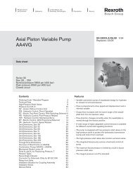
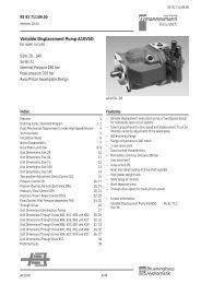
RE 91 001/09.00RE 91 001/09.00replaces: 01.97<strong>Fixed</strong> <strong>Displacement</strong> <strong>Motor</strong> <strong>A2FM</strong>open and closed circuitsSizes 5...1000Series 6Nom. Pressure up to 400 barPeak Pressure up to 450 bar<strong>A2FM</strong>IndexFeatures 1Ordering Code / Standard Program 2Technical Data 4...7Ordering Code / Standard Program - Size 5 8Unit Dimensions, Size 5 8Unit Dimensions, Sizes 10,12,16 9Unit Dimensions, Sizes 23, 28, 32 10...11Unit Dimensions, Size 45 12...13Preferred types 13Unit Dimensions, Sizes 56, 63 14...15Unit Dimensions, Sizes 80, 90 16Unit Dimensions, Sizes 107, 125 17Unit Dimensions, Sizes 160, 180 18Unit Dimensions, Size 200 19Unit Dimensions, Size 250 20Unit Dimensions, Size 355 21Unit Dimensions, Size 500 22Unit Dimensions, Size 710 23Unit Dimensions, Size 1000 24Speed sensor 25Flushing valves 25Pressure relief valves 26Motion Control Valve 27Installation and Commissioning Guidelines 28Features– <strong>Fixed</strong> displacement motor <strong>A2FM</strong> of axial piston, bent axis design,suitable for hydrostatic drives in open and closed circuits– Use in mobile and industrial applications– Output speed is proportional to input flow and inversely proportionalto displacement– Drive torque increases with the pressure drop across the unit– Careful selection of the displacements offered, permit sizes to bematched to practically every application– Favourable power / weight ratio– Compact design– Optimum efficiency– Economical conception– One piece pistons with piston rings<strong>A2FM</strong> 1/28
RE 91 001/09.00Ordering Code / Standard Program(Ordering code size 5 see page 8)Hydraulic fluidMineral oil (no code)HFB-, HFC-, HFD- sizes 10...200 (no code)Hydraulic fluid sizes 250...1000 (only in connection with drive shaft bearings "L") E-Axial piston unitBent axis design, fixed displacementA2FDrive shaft bearings 10...200 250...500 710...1000Mechanical bearings (no code) —Long-Life bearings — LMode of operation<strong>Motor</strong> (Plug-in motor A2FE see RE 91008)MSize<strong>Displacement</strong> V g (cm 3 )5 10 12 16 23 28 32 45 56 63 80 90 107 125 160 180 200 250 355 500 710 1000Sizes 5...200: production Elchingen Plant; Sizes 250...1000: production Horb PlantSeriesIndexsizes 10...180 1size 200 3sizes 250...1000 06Direction of rotationviewed on shaft end alternating WSealsFKM (flour-caoutchouc)VShaft end 10 12 16 23 28 32 45 56 63 80 90 107 125 160 180 200 250 355 500 710 1000Splined shaft – – – – – ADIN 5480 – – – – – – – ZParallel shaft with – – – – – – Bkey, DIN 6885 – – – – – – – PMounting flange 10...250 355...1000ISO 4-hole – BISO 8-hole – H= available– = not available= preferred program (preferred types see page 13)Brueninghaus Hydromatik 2/28 <strong>A2FM</strong>
RE 91 001/09.00A2F M / 6 W - <strong>VH</strong>ydraulic fluidAxial piston unitDrive shaft bearingsMode of operationSizeSeriesIndexDirection of rotationSealsShaft endMounting flangeService line connections 1 ) 10 12 16 23 28 32 45 56 63 80 90 107 125 160 180 200 250 355 500 710 1000Ports A and B 01 0 – – – 010SAE, at rear end 6 – – – – – – – – – – – – – 016Ports A and B 02 0 – – – – – – – – 020SAE, opposite side 6 – – – – – – – – – – – – – 0267 – – – – – – – – – – – 027Ports A and B 03 0 – – – – – – – – – – – – – – – 030threads, at side, opposite side 6 – – – – – – – – – – – – – – – – – – 036Ports A and B 04 0 – – – – – – – 2 ) – – – – 040threads, at side and rear end 6 – – – – – – – – – – – – – – – 046Ports A and B 10 0 – – – – – – – – – 100SAE, at side, same side 6 – – – – – – – – – – – – – – 106port plate with press. relief valve 18 1and built-on motion control valve – – – – – – – – – – 181Port plate with integrated 19 1 – – – – – – – – – – 191pressure relief valves 2 – – – – – – – – – – 192Valveswithout valves 0with pressure relief valves (without pressure sequence range) 1with pressure relief valves (with pressure sequence range) 2with integrated flushing valve 6with built-on flushing and boost valve 7Speed sensing control 10...16 23...180 200 250...1000without speed sensing control (no code)prepared for speed sensing control — — DSpecial designwithout special design (standard type, no code)special design for slew drive applications (standard for port plate 19)1 ) Threads of fixing screws and service lines are metric2 ) ports at rear end are pluggedJ<strong>A2FM</strong> 3/28 Brueninghaus Hydromatik
RE 91 001/09.00Technical DataFluidTo review the application of <strong>A2FM</strong> motors with the selected hydraulicfluid, detailed fluid compatibility and application data can be foundin data sheets RE 90220 (mineral oil), RE 90221 (environmentallyacceptable hydraulic fluids) and RE 90223 (fire resistant fluids, HF).The fixed motor <strong>A2FM</strong> is not suitable for operation with HFA. Whenusing HFB-, HFC-, HFD- or environmentally acceptable hydraulic fluidspossible limitations for the technical data have to be taken intoconsideration. If necessary please consult our technical department(please indicate type of the hydraulic fluid used for your applicationon the order sheet).Operating viscosity rangeIn order to optain optimum efficiency and service life, we recommendthat the operating viscosity (at operating temperature) be selectedfrom within the rangeν opt = opt. operating viscosity 16...36 mm 2 /sreferred to the loop temperature (closed circuit) or tank temperature(open circuit).Viscosity limitsThe limiting values for viscosity are as follows:sizes 5...200ν min =5 mm 2 /s, short term at a max. permissible temperature of t max = 115°Cν max = 1600 mm 2 /s, short term on cold start (t min = -40°C)sizes 250...1000ν min = 10 mm 2 /s, short term at a max. permissible leakage oil temp. of t max = 90°Cν max = 1000 mm 2 /s, short term on cold start (t min = -25°C)Please note that the max. fluid temperature is also not exceeded incertain areas (for instance bearing area).At temperatures of -25°C up to -40°C special measures may berequired for certain installation positions. Please contact us for furtherinformation.Selection diagramviscosity ν in mm 2 /s2500-40° -20° 0° 20° 40° 60° 80° 100°1600100060040020010060402010VG 22VG 32VG 46VG 68VG 100Notes on the selection of the hydraulic fluidIn order to select the correct fluid, it is necessary to know the operatingtemperature in the loop (closed circuit) or the tank temperature (opencircuit) in relation to the ambient temperature.The hydraulic fluid should be selected so that within the operatingtemperature range, the operating viscosity lies within the optimumrange (ν opt ) (see shaded section of the selection diagram). Werecommend that the highest possible viscosity range should be chosenin each case.Example: At an ambient temperature of X°C the operatingtemperature (closed circuit: loop temperature; open circuit: tanktemperature) is 60°C. Within the operating viscosity range (ν opt ;shaded area), this corresponds to viscosity ranges VG 46 or VG 68.VG 68 should be selected.Important: The leakage oil (case drain oil) temperature is influencedby pressure and motor speed and is always higher than the circuit ortank temperature. However, at no point in the circuit may thetemperature exceed 115°C for sizes 5...200 or 90°C for sizes250...1000.If it is not possible to comply with the above conditions because ofextreme operating parameters or high ambient temperatures pleaseconsult us.FiltrationThe finer the filtration the better the achieved purity grade of thepressure fluid and the longer the life of the axial piston unit. To ensurethe functioning of the axial piston unit a minimum purity grade of9 to NAS 163818/15 to ISO/DIS 4406 is necessary.At very high temperatures of the hydraulic fluid (90°C to max. 115°C,notpermissible for sizes 250...1000) at least cleanless class8 to NAS 163817/14 to ISO/DIS 4406 is necessary.If above mentioned grades cannot be maintained please consult us.16003616ν opt.55-40° -25° -10° 0° 10° 30° 50° 70° 90° 115°temperature t in °Ct min = -40°Cfluid temperature ranget max = +115°CBrueninghaus Hydromatik 4/28 <strong>A2FM</strong>
RE 91 001/09.00Technical DataWorking pressure rangemaximum pressure at port A or B (Pressure data to DIN 24312)Size 5 Shaft end B Shaft end CNominal pressure p N 210 bar 315 barPeak pressure p max 250 bar 350 barSize 10...200 1 ) Shaft end A, Z 2 ) Shaft end B, PNominal pressure p N 400 bar 350 barPeak pressure p max 450 bar 400 bar1 ) Attention: shaft end Z and P with drives of radial force loads atthe drive shaft necessitate reduction of the nominal pressure top N = 315 bar.2 ) Shaft end Z to size 56: p N = 350 bar, p max = 400 barSizes 250...1000Nominal pressure p NPeak pressure p max350 bar400 barWith pulsating loads above 315 bar we recommend using the modelwith splined shaft, standard version A (sizes 10...200) or with splinedshaft Z (sizes 250...1000).The summ of the pressures at ports A und B may not exceed 700 bar(630 bar, A2F 5).Direction of flowClockwise rotationA to BAnti-clockwise rotationB to ASpeed rangeThere is no limitation on minimum speed n min . If uniformity of rotationis required, however, speed n min should not be allowed to fall below50 rpm. See table on page 6 for max. permissible speeds.Long-Life bearings (L) (sizes 250...1000)(for high life expectancy and use of HF-fluids)The outer dimensions of the axial piston motors are identical tostandard design (without long life bearings). The change from standarddesign to long life bearing system is possible.We recommend to apply bearing flushing at port U.Bearing flushingFor sizes 250…1000 bearing and housing flushing is possible throughport U.Flows (recommendation)Sizes 250 355 500 710 1000q flush (L/min) 10 16 20 25 25Case drain pressureShaft seal ring FKM (fluor-caoutchouc)The lower the speed and the case drain pressure the higher the lifeexpectation of the shaft seal ring. The values shown in the diagramare permissible loads of the seal ring and shall not be exceeded.At stationary pressure loads in the range of the max. admissibleleakage pressure a reduction of the life experience of the seal ringwill result.For a short period (t < 5 min.) are for the sizes 10…200 pressureloads up to 5 bar independent from rotational speeds are permissible.Sizes 10...200perm. pressure p abs. max.(bar)perm. pressure p abs. max.(bar)1098765Sizes 80, 904Sizes 107, 1253Sizes 160, 1802Size 20010 1000 2000 3000Sizes 250...1000654324000 5000 6000 7000 8000speed n (min -1 )10 500 1000 1500 2000 2500speed n (min -1 )Note:- max. permissible motor speeds are given in the table on page 6- max. perm. housing pressure p abs. max ____ 10 bar (sizes 5...200)_____ 6 bar (sizes 250...1000)- the pressure in the housing must be the same as or greater thanthe external pressure on the shaft seal.SymbolSizes 710, 1000ConnectionsA, B Service line portsT Drain portSize 500TSizes 10, 12, 16Sizes 23, 28, 32ABSizes 45Sizes 56, 63Size 250Size 355<strong>A2FM</strong> 5/28 Brueninghaus Hydromatik
RE 91 001/09.00Technical DataTable of values (theoretical values, without considering η mhand η v; values rounded)Size 5 10 12 16 23 28 32 45 56 63 80<strong>Displacement</strong> V gcm 3 4,93 10,3 12 16 22,9 28,1 32 45,6 56,1 63 80,4Max. Speed n maxmin -1 10 000 8000 8000 8000 6300 6300 6300 5600 5000 5000 4500n max intermit. 1 ) min -1 11 000 8800 8800 8800 6900 6900 6900 6200 5500 5500 5000Max. flow n maxq V maxL/min 49 82 96 128 144 176 201 255 280 315 360Torque constants T KNm/bar 0,076 0,164 0,19 0,25 0,36 0,445 0,509 0,725 0,89 1,0 1,27Torque at ∆p = 350 bar T Nm 24,7 2 ) 57 67 88 126 156 178 254 312 350 445∆p = 400 bar T Nm – 65 76 100 144 178 204 290 356 400 508Case volume L 0,17 0,17 0,17 0,20 0,20 0,20 0,33 0,45 0,45 0,55Moment of inertiaJ kgmabout drive axis2 0,00008 0,0004 0,0004 0,0004 0,0012 0,0012 0,0012 0,0024 0,0042 0,0042 0,0072Weight (approx.) m kg 2,5 5,4 5,4 5,4 9,5 9,5 9,5 13,5 18 18 23Size 90 107 125 160 180 200 250 355 500 710 1000<strong>Displacement</strong> V gcm 3 90 106,7 125 160,4 180 200 250 355 500 710 1000Max. Speed n maxmin -1 4500 4000 4000 3600 3600 2750 2500 2240 2000 1600 1600n 1 max intermit.) min -1 5000 4400 4400 4000 4000 3000 – – – – –Max. flow n maxq V maxL/min 405 427 500 577 648 550 625 795 1000 1136 1600Torque constants T KNm/bar 1,43 1,70 1,99 2,54 2,86 3,18 3,98 5,65 7,96 11,3 15,9Torque at ∆p = 350 bar T Nm 501 595 697 889 1001 1114 1393 1978 2785 3955 5570∆p = 400 bar T Nm 572 680 796 1016 1144 1272 – – – – –Case volume L 0,55 0,8 0,8 1,1 1,1 2,5 3,5 7,8Moment of inertiaJ kgmabout drive axis2 0,0072 0,0116 0,0116 0,0220 0,0220 0,0378 0,061 0,102 0,178 0,55 0,55Weight (approx.) m kg 23 32 32 45 45 66 73 110 155 322 3361 ) Intermittent max. speed: overspeed at discharge and overtaking travel operations, t < 5 sek. and ∆p < 150 bar2 ) ∆p = 315 barCalculation of sizeV g • nFlow q V = in L/min1000 • η vq V • 1000 • η vOutput speed n = in min -1V gV g • ∆p • η mhOutout torque T = 20 • πor T = T K • ∆p • η mh in Nm2 π • T • n T • nOutput power P = =60 000 9549V g = geometric displacement in cm 3per rev.T = torque in Nm∆p = pressure differential in barn = speed in min -1T K = torque constants in Nm/barη v= volumetric efficiencyη mh = mech.-hyd. efficiencyη t= overall efficiencyq V • ∆p= • η t in kW600Brueninghaus Hydromatik 6/28 <strong>A2FM</strong>
RE 91 001/09.00Technical DataOutput drivePermissible axial and radial loads on drive shaftThe values given are maximum values and do not apply to continuous operationSize 5 10 12 16 23 28 32 45 56 63 80a mm 12 16 16 16 16 16 16 18 18 18 20F q maxN 710 2350 2750 3700 4300 5400 6100 8150 9200 10300 11500±F ax maxN 180 320 320 320 500 500 500 630 800 800 1000±F ax perm./bar N/bar 1,5 3,0 3,0 3,0 5,2 5,2 5,2 7,0 8,7 8,7 10,6Size 90 107 125 160 180 200 250 355 500 710 1000a mm 20 20 20 25 25 25 41 52,5 52,5 67,5 67,5F q maxN 12900 13600 15900 18400 20600 22900 1200 1 ) 1500 1 ) 1900 1 ) 3000 1 ) 2600 1 )±F ax maxN +F ax max1000 1250 1250 1600 1600 1600 4000 5000 6250 10000 10000- F ax max1000 1250 1250 1600 1600 1600 1200 1500 1900 3000 2600±F ax perm./bar N/bar 10,6 12,9 12,9 16,7 16,7 16,7 2 ) 2 ) 2 ) 2 ) 2 )1 ) Axial piston unit stationary or in bypass operation, please contact us when appearing higher forces!2 ) Please contact us!Code explanationa= distance of F q from shaft shoulderF q max = max. perm. radial force at distance a(at intermittent operation)±F ax max = max. perm. axial force when stationaryor when axial piston unit is running at zero pressure±F ax perm. /bar = perm. axial force/bar operating pressureThe direction of the max. perm. axial force must be noted by sizes28...200:- F ax = increases bearing life+ F ax = reduces bearing life(avoid if possible)Optimal force direction of F q (valid for sizes 10...180)By means of appropriate force directions of F q the bearing load causedby inside rotary group forces can be reduced. An optimal lifeexpectation of the bearing can be reached.Minimum inlet pressure at port A (B)In order to avoid damage of the variable motor a minimum inletpressure at the inlet zone must be assured. The minimum inlet pressureis related to the rotational speed of the fixed motor.ϕ opt =70°<strong>Motor</strong> alternating beiwechselnder rotationDrehrichtungϕ opt =70°ϕ opt = 45°ϕ opt = 45°A B A Banti-clockwise <strong>Motor</strong> Linkslauf rotation<strong>Motor</strong> clockwide Rechtslauf rotation anti-clockwise <strong>Motor</strong> Linkslauf rotationDruck amDruck amDruck ampressure Anschluß at port B BAnschluß pressure at Aport Apressure Anschluß at port Bmin. inlet pressure p abs. min (bar)12108642100,20,40,60,8 1,0speed n/n max<strong>A2FM</strong> 7/28 Brueninghaus Hydromatik
RE 91 001/09.00Ordering Code / Standard Program - Size 5Axial piston unitBent axis design, fixed displacementA2FSize<strong>Displacement</strong> V g (cm 3 ) 5Direction of rotationviewed on shaft end alternating WSeriesA2F 5 W 6.0 36.0Additional instructions in text formSealsThe fixed motor A2F5 is equipped with NBR- (Nitril-caoutchouc)Seals in standard design.In case of need FKM- (fluor-caoutchouc) sealsplease indicate when ordering in clear text:"with FKM-seals"Shaft endParallel shaft with key DIN 6885Tapered shaft with spigot and spring washer DIN 6888Service line connectionsThreads at side, metric 3BC= preferred program(preferred types see page 13)Unit Dimensions, Size 5Before finalising your design, please request a certified drawing.h8817,574,558,5YR 670Detail YTAø604T51 8025°ø48,575 ±0,16,470TB62Shaft endsBParallel shaft with key,DIN 6885 A4x4x20p N = 210 barCTapered shaft with spigotand spring washer 3x5DIN 6888, p N = 315 barConnectionsB, (A) Service line ports M 18x1,5T Drain port M 10x1, both sidestaper 1:10Brueninghaus Hydromatik 8/28 <strong>A2FM</strong>
RE 91 001/09.00Unit Dimensions, Sizes 10,12,16Before finalising your design, please request a certified drawing.20 12664,5T 15R 1045°9545°see port platesø80 h640°53,5541,510095918,2T 2ø85ABConnectionsA, B Service line ports (see port plates)T 1 , T 2 Drain ports (1 port plugged) M 12x1,5Port plates03 Threaded ports, at side 04 Threaded ports, at side and rear end108108BA1 155,5BA55,569,591BA130,51669185130,51471663485A, B Service line ports M 22x1,5A, B, A 1 , B 1 Service line ports M 22x1,5Shaft endsSizes 10, 12, 16 Sizes 10, 12A Splined shaft, DIN 5480 Z Splined shaft, DIN 5480W 25x1,25x30x18x9g W 20x1,25x30x14x9gp N = 400 barp N = 400 barSizes 10, 12, 16 Sizes 10, 12B Parallel shaft with key, P Parallel shaft with key,DIN 6885, AS 8x7x32 DIN 6885, AS 6x6x32p N = 350 barp N = 350 bar<strong>A2FM</strong> 9/28 Brueninghaus Hydromatik
RE 91 001/09.00Unit Dimensions, Sizes 23, 28, 32Before finalising your design, please request a certified drawing.60,725 188T 145°11845°19see port platesR 12ø100 h623,255,540°T 21948,5ø106A12511B118ConnectionsA, B Service line ports (see port plates)T 1 , T 2 Drain ports (1 port plugged) M 16x1,5Port plates12111540,5 40,5BA18,213718,240,5137810670BA1531731359144190117120A, B Service line ports SAE 1 / 2 "420 bar (6000 psi) high pressure seriesA, B Service line ports SAE 1 / 2 "420 bar (6000 psi) high pressure series03 Threaded ports, at side 04 Threaded ports, at side and rear end137137BA1 1BA11701 SAE-ports, at rear end02 SAE-ports, at sideM8; 15 deepM8; 15 deep707088117BA14419012014416619058120A, B Service line ports M 27x2A, B, A 1 , B 1 Service line ports M 27x2Brueninghaus Hydromatik 10/28 <strong>A2FM</strong>
RE 91 001/09.00Unit Dimensions, Sizes 23, 28, 32Before finalising your design, please request a certified drawing.Port plates10 SAE-ports, at side, same sideDetail Y14940131581789110659M8; 15 deep18,2BA40,5 40,5115YA, B Service line ports SAE 1 / 2 "420 bar (6000 psi) high pressure seriesShaft endsSizes 23, 28, 32 Sizes 23, 28A Splined shaft, DIN 5480 Z Splined shaft, DIN 5480W 30x2x30x14x9gW 25x1,25x30x18x9gp N = 400 barp N = 400 barSizes 23, 28, 32 Sizes 23, 28B Parallel shaft with key, P Parallel shaft with key,DIN 6885, AS 8x7x40 DIN 6885, AS 8x7x40p N = 350 barp N = 350 bar<strong>A2FM</strong> 11/28 Brueninghaus Hydromatik
RE 91 001/09.00Unit Dimensions, Size 45Before finalising your design, please request a certified drawing.60,332 2012T 145°15045°see port platesR 1618ø125 h66340 °185216013,515030T 2ø118ABConnectionsA, B Service line ports (see port plates)T 1 , T 2 Drain ports (1 port plugged) M 18x1,5Port plates01 SAE-ports, at rear end02 SAE-ports, at side13850,8B14750,8A50,81915523,88912223,880BA1661941975M10;17 deepM10; 17 deep155207133128A, B Service line ports SAE 3 / 4 "420 bar (6000 psi) high pressure seriesA, B Service line ports SAE 3 / 4 "420 bar (6000 psi) high pressure series04 Threaded ports, at side and rear end 10 SAE-ports, at side, same sideDetail Y155B 1 A11674915517920780100133B58128A169193Y1021191477519M10; 17deepBA23,850,850,8A, B, A 1 , B 1 Service line ports M 33x2A, B Service line ports SAE 3 / 4 "420 bar (6000 psi) high pressure seriesBrueninghaus Hydromatik 12/28 <strong>A2FM</strong>
RE 91 001/09.00Unit Dimensions, Size 45Before finalising your design, please request a certified drawing.Shaft endsA Splined shaft, DIN 5480 Z Splined shaft, DIN 5480W 32x2x30x14x9gW 30x2x30x14x9gp N = 400 barp N = 400 barP Parallel shaft with key,DIN 6885, AS 8x7x50p N = 350 barPreferred types (please state type and ident-no. when ordering)TypeIdent-No.TypeIdent-No.A2F5W6.0B3 9404451<strong>A2FM</strong>10/61W-VAB030 9423386<strong>A2FM</strong>10/61W-VBB030 9610656<strong>A2FM</strong>12/61W-VAB030 9424240<strong>A2FM</strong>12/61W-VBB030 9610657<strong>A2FM</strong>16/61W-VAB030 9411111<strong>A2FM</strong>16/61W-VBB030 9411119<strong>A2FM</strong>23/61W-VAB010 9427351<strong>A2FM</strong>23/61W-VAB020 9422092<strong>A2FM</strong>23/61W-VAB040 9428415<strong>A2FM</strong>23/61W-VBB010 9610658<strong>A2FM</strong>23/61W-VBB020 9610659<strong>A2FM</strong>23/61W-VBB040 9610660<strong>A2FM</strong>28/61W-VAB010 9424853<strong>A2FM</strong>28/61W-VAB020 9422548<strong>A2FM</strong>28/61W-VAB040 9421629<strong>A2FM</strong>28/61W-VBB010 9610661<strong>A2FM</strong>28/61W-VBB020 9610662<strong>A2FM</strong>28/61W-VBB040 9610663<strong>A2FM</strong>32/61W-VAB010 9410189<strong>A2FM</strong>32/61W-VAB020 9410190<strong>A2FM</strong>32/61W-VAB040 9410192<strong>A2FM</strong>32/61W-VBB010 9410194<strong>A2FM</strong>32/61W-VBB020 9410195<strong>A2FM</strong>32/61W-VBB040 9410197<strong>A2FM</strong>45/61W-VZB010 9411581<strong>A2FM</strong>45/61W-VZB020 9411582<strong>A2FM</strong>45/61W-VZB040 9411584<strong>A2FM</strong>56/61W-VAB010 9424905<strong>A2FM</strong>56/61W-VAB020 9422129<strong>A2FM</strong>56/61W-VAB040 9429251<strong>A2FM</strong>56/61W-VBB010 9610664<strong>A2FM</strong>56/61W-VBB020 9610665<strong>A2FM</strong>56/61W-VBB040 9605544<strong>A2FM</strong>63/61W-VAB010 9408523<strong>A2FM</strong>63/61W-VAB020 9408524<strong>A2FM</strong>63/61W-VAB040 9408526<strong>A2FM</strong>63/61W-VBB010 9408514<strong>A2FM</strong>63/61W-VBB020 9408549<strong>A2FM</strong>63/61W-VBB040 9408551<strong>A2FM</strong>80/61W-VAB010 9422638<strong>A2FM</strong>80/61W-VAB020 9422089<strong>A2FM</strong>80/61W-VBB010 9610666<strong>A2FM</strong>80/61W-VBB020 9610667<strong>A2FM</strong>90/61W-VAB010 9408463<strong>A2FM</strong>90/61W-VAB020 9408464<strong>A2FM</strong>90/61W-VBB010 9408468<strong>A2FM</strong>90/61W-VBB020 9408469<strong>A2FM</strong>107/61W-VAB010 9424300<strong>A2FM</strong>107/61W-VAB020 9424093<strong>A2FM</strong>107/61W-VBB010 9610668<strong>A2FM</strong>107/61W-VBB020 9610669<strong>A2FM</strong>125/61W-VAB010 9409630<strong>A2FM</strong>125/61W-VAB020 9409634<strong>A2FM</strong>125/61W-VBB010 9409637<strong>A2FM</strong>125/61W-VBB020 9409638<strong>A2FM</strong>160/61W-VAB010 9425163<strong>A2FM</strong>160/61W-VAB020 9424094<strong>A2FM</strong>160/61W-VBB010 9610670<strong>A2FM</strong>160/61W-VBB020 9610671<strong>A2FM</strong>180/61W-VAB010 9409189<strong>A2FM</strong>180/61W-VAB020 9409190<strong>A2FM</strong>180/61W-VBB010 9409372<strong>A2FM</strong>180/61W-VBB020 9409373<strong>A2FM</strong>200/63W-VAB010 2011528<strong>A2FM</strong>250/60W-VZB010 915383<strong>A2FM</strong>250/60W-VZB020 910653<strong>A2FM</strong>355/60W-VZH010 920780<strong>A2FM</strong>500/60W-VPH010 943251<strong>A2FM</strong>500/60W-VZH010 968982A2FLM710/60W-VPH010 969815A2FLM710/60W-VZH010 965974<strong>A2FM</strong>1000/60W-VPH010 949444<strong>A2FM</strong>1000/60W-VZH010 944773<strong>A2FM</strong> 13/28 Brueninghaus Hydromatik
RE 91 001/09.00Unit Dimensions, Sizes 56, 63Before finalising your design, please request a certified drawing.321067,520T 145°15045°see port plates18R 16ø125 h67040°185616013,515030T 2ø128ABConnectionsA, B Service line ports (see port plates)T 1 , T 2 Drain ports (1 port plugged) M 18x1,5Port plates01 SAE-ports, at rear end02 SAE-ports, at side149,59613014750,8 50,8BA23,850,819166,523,887142BA1822061975M10; 17 deepM10; 17 deep171225136A, B Service line ports SAE 3 / 4 "420 bar (6000 psi) high pressure seriesA, B Service line ports SAE 3 / 4 "420 bar (6000 psi) high pressure series04 Threaded ports, at side and rear end 10 SAE-ports, at side, same sideDetail Y166,5B 1 A 11764917119522587107142B58136A1822061071301477519M10; 17 deepBA50,850,823,8A, B, A 1 , B 1 Service line ports M 33x2YA, B Service line ports SAE 3 / 4 "420 bar (6000 psi) high pressure seriesBrueninghaus Hydromatik 14/28 <strong>A2FM</strong>
RE 91 001/09.00Unit Dimensions, Sizes 56, 63Before finalising your design, please request a certified drawing.Shaft endsSizes 56, 63 Size 56A Splined shaft, DIN 5480 Z Splined shaft, DIN 5480W 35x2x30x16x9gW 30x2x30x14x9gp N = 400 barp N = 350 barSizes 56, 63 Size 56B Parallel shaft with key, P Parallel shaft with key,DIN 6885, AS 10x8x50 DIN 6885, AS 8x7x50p N = 350 barp N = 350 bar<strong>A2FM</strong> 15/28 Brueninghaus Hydromatik
RE 91 001/09.00Unit Dimensions, Sizes 80, 90Before finalising your design, please request a certified drawing.78,532 2010T 145°16545°15see port platesR 16ø140 h68340°156118013,516529T 2ø138ABConnectionsA, B Service line ports (see port plates)T 1 , T 2 Drain ports (1 port plugged) M 18x1,5Port plates01 SAE-ports, at rear end02 SAE-ports, at side10 SAE-ports, at side, same side203233162,5104,514516657,2 57,2B2584A27,8M12;17 deep57,225196257189,527,8B A991621211451668425160206236M12; 17 deep M12; 17 deep198Detail Y60BA57,257,227,8A, B Service line ports SAE 1"420 bar (6000 psi) high pressure seriesA, B Service line ports SAE 1"420 bar (6000 psi) high pressure seriesYA, B Service line ports SAE 1"420 bar (6000 psi) high pressure seriesShaft endsSizes 80, 90 Size 80A Splined shaft, DIN 5480 Z Splined shaft, DIN 5480W 40x2x30x18x9gW 35x2x30x16x9gp N = 400 barp N = 400 barSizes 80, 90 Size 80B Parallel shaft with key, P Parallel shaft with key,DIN 6885, AS 12x8x56 DIN 6885, AS 10x8x56p N = 350 barp N = 350 barBrueninghaus Hydromatik 16/28 <strong>A2FM</strong>
RE 91 001/09.00Unit Dimensions, Sizes 107, 125Before finalising your design, please request a certified drawing.82,845°45°ø160 h636,540 23T 1108540°6718see port plates19018AT 2ø150R 2020017,5190BConnectionsA, B Service line ports (see port plates)T 1 , T 2 Drain ports (1 port plugged) M 18x1,5Port plates01 SAE-ports, at rear end186,512015919466,7 66,7BA31,802 SAE-ports, at side(Klammermaße für NG 107!)66,7(57,2)32(25)22231,8(27,8)110BA10 SAE-ports, at side, same side2241361571949932Detail Y70B66,7225,52523299M14;19 deep213285181M14; 19 deep(M12; 17 deep)178226261M14; 19 deepY 31,866.7AA, B Service line ports SAE 1 1 / 4 "420 bar (6000 psi) high pressure seriesA, B Service line ports SAE 1 1 / 4 "(1")420 bar (6000 psi) high pressure seriesA, B Service line ports SAE 1 1 / 4 "420 bar (6000 psi) high pressure seriesShaft endsSizes 107, 125 Size 107A Splined shaft, DIN 5480 Z Splined shaft, DIN 5480W 45x2x30x21x9gW 40x2x30x18x9gp N = 400 barp N = 400 barSizes 107, 125 Size 107B Parallel shaft with key, P Parallel shaft with key,DIN 6885, AS 14x9x63 DIN 6885, AS 12x8x63p N = 350 barp N = 350 bar<strong>A2FM</strong> 17/28 Brueninghaus Hydromatik
RE 91 001/09.00Unit Dimensions, Sizes 160, 180Before finalising your design, please request a certified drawing.9340 2510T 1R 2045 °21045 °19,5see port platesø180 h695,540°19,577,522417,521037,2T 2ø180ABConnectionsA, B Service line ports (see port plates)T 1 , T 2 Drain ports (1 port plugged) M 22x1,5Port plates01 SAE-ports, at rear end25229420813418819466,7 66,7B AM14;19 deepA, B Service line ports SAE 1 1 / 4 "420 bar (6000 psi) high pressure series329931,802 SAE-ports, at side66,73223729423331,8121188M14; 19 deep202A, B Service line ports SAE 1 1 / 4 "420 bar (6000 psi) high pressure seriesBA10 SAE-ports, at side, same side2522441491851949932Detail Y290 M14; 19 deep 31,8YA, B Service line ports SAE 1 1 / 4 "420 bar (6000 psi) high pressure series7066,7A66,7BShaft endsSizes 160, 180Size160A Splined shaft, DIN 5480 Z Splined shaft, DIN 5480W 50x2x30x24x9gW 45x2x30x21x9gp N = 400 barp N = 400 barSizes 160, 180 Size 160B Parallel shaft with key, P Parallel shaft with key,DIN 6885, AS 14x9x70 DIN 6885, AS 14x9x70p N = 350 barp N = 350 barBrueninghaus Hydromatik 18/28 <strong>A2FM</strong>
RE 91 001/09.00Unit Dimensions, Size 200Before finalising your design, please request a certified drawing.°40910432Tsee port plates4523645°15-0,0292225°92ø200102,51525023632T211ABConnectionsA, B Service line ports (see port plates)T 1 , T 2 Drain ports (1 port plugged) M 22x1,5Port plates01 SAE-ports, at rear end199B20466,766,7A1658431,82843093299M14;19 deepA, B Service line ports SAE 1 1 / 4 "420 bar (6000 psi) high pressure seriesShaft endsA Splined shaft, DIN 5480W 50x2x30x24x9gp N = 400 barBParallel shaft with key,DIN 6885, AS 14x9x80p N = 350 bar<strong>A2FM</strong> 19/28 Brueninghaus Hydromatik
1728221017282210RE 91 001/09.00Unit Dimensions, Size 250Before finalising your design, please request a certified drawing.5098222UT45°24645°ø224h8105 10526°30´2802461241722582T22ConnectionsA, B Service line ports (see port plates)T 1 , T 2 Drain ports (1 port plugged) M 22x1,5U Port for bearing flushing (plugged) M 14x1,5Port plates01 SAE-ports, at rear end02 SAE-ports, at side28866,766,7267236BA31,8210M14; 19 deepBA933143250 5032M14;19 deep3233266,7A, B Service line ports SAE 1 1 / 4 "high pressure seriesA, B Service line ports SAE 1 1 / 4 "high pressure series04 Threaded ports, at side and rear endShaft ends267BB1236A1AZ Splined shaft, DIN 5480W 50x2x30x24x9gp N = 350 barP Parallel shaft with key,DIN 6885, AS 14x9x80p N = 350 bar3252285A, B Service line ports M 48x2A 1 , B 1 Service line ports (plugged) M 48x2Brueninghaus Hydromatik 20/28 <strong>A2FM</strong>
24579,419812833510218128170RE 91 001/09.00Unit Dimensions, Size 355Before finalising your design, please request a certified drawing.Port plate 0150148323,5UT32045°22°30´335360ø280 h826°30´3202883T350XDetail XB36,636,6APort plate 10Detail XM14; 22 deepM BBMBMA14819924112066,73240 4060 60250M16; 21 deep323370,5XM A31,8 AConnectionsA, B Service line ports port plate 01 SAE 1 1 / 2 "port plate 10 SAE 1 1 / 4 "T Drain ports ( 1 port plugged) M 33x2U Port for bearing flushing (plugged) M 14x1,5M A , M B Test ports operating pressure (plugged) M 14x1,5Shaft endsZ Splined shaft, DIN 5480 P Parallel shaft with key,W 60x2x30x28x9gDIN 6885, AS 18x11x100p N = 350 barp N = 350 bar<strong>A2FM</strong> 21/28 Brueninghaus Hydromatik
RE 91 001/09.00Unit Dimensions, Size 500Before finalising your design, please request a certified drawing.361,522°30´50 9814 27,545°375UT220142ø315112,5h81424002219226°30´36037530TX111396Detail X27636,6 36,6BAM AConnectionsMB79,4270A, B Service line ports SAE 1 1 / 2 "high pressure seriesT Drain ports (1 port plugged) M 33x2U Port for bearing flushing (plugged) M 18x1,5M A , M B Test ports operating pressure (plugged) M 14x1,540654065M16; 21 deepShaft endsZ Splined shaft, DIN 5480 P Parallel shaft with key,W 70x3x30x22x9gDIN 6885, AS 20x12x100p N = 350 barp N = 350 barBrueninghaus Hydromatik 22/28 <strong>A2FM</strong>
RE 91 001/09.00Unit Dimensions, Size 710Before finalising your design, please request a certified drawing.48622°30´50 13114 41,5UT45°465ø400 h8236183 18318°30´10225222X50045046535156T507Detail X34444,544,5BAM AConnectionsM B96,8340A, B Service line ports SAE 2"High pressure seriesT Drain port (plugged) M 42x2M20; 30 deepU Port for bearing flushing (plugged) M 18x1,5M A , M B Test ports operating pressure (plugged) M 14x1,550858550Shaft endsZ Splined shaft, DIN 5480 P Parallel shaft with key,W 90x3x30x28x9gDIN 6885, AS 25x14x125p N = 350 barp N = 350 bar<strong>A2FM</strong> 23/28 Brueninghaus Hydromatik
RE 91 001/09.00Unit Dimensions, Size 1000Before finalising your design, please request a certified drawing.50 13114 41,5UT46845°22°30´465500ø400183143465h82218323626°30´45035156T512279XDetail X34444,5 44,5M AConnectionsA, B Service line ports SAE 2"high pressure seriesT Drain ports (1 port plugged) M 42x2U Port for bearing flushing (plugged) M 18x1,5M A , M B Test ports operating pressure (plugged) M 14x1,5MBB50A5096,8340M20; 30 deep8585Shaft endsZ Splined shaft, DIN 5480 P Parallel shaft with key,W 90x3x30x28x9gDIN 6885, AS 25x14x125p N = 350 barp N = 350 barBrueninghaus Hydromatik 24/28 <strong>A2FM</strong>
RE 91 001/09.00Flushing valvesBuilt-on flushing and boost pressure relief valve (7)This valve is built on to the fixed displacement motor. It must then benoted that only a port plate with ports at side is then available(port plate 02).The flushing and boost pressure relief valve has a fixed setting of 16bar (the setting of the primary boost pressure relief valve must benoted) and is used to safeguard the minimum boost pressure. A fixedflow of fluid is taken via anT2 A (B)orifice from the lowpressure side of the circuitand fed into the motorhousing. This flow is thenpassed back to tank withthe case drain fluid. Fluidthus removed from theclosed circuit must beT 1 B (A)made up by means of theboost pump.A1YA2AB98Size 45 56, 63 80, 90 107, 125 160, 180 250A1 223 239 268 294 315 344A2 151 159 173,5 192 201 154Size Flushing flow (at low pressure ∆p = 25 bar) *45, 56, 63 3,5 L/min Orifice-No.: 651766/503.12.01.0180, 90 5 L/min Orifice-No.: 419695/503.12.01.01107, 125 8 L/min Orifice-No.: 419696/503.12.01.01160, 180 10 L/min Orifice-No.: 419697/503.12.01.01250 10 L/min* Standard flushing volumes(for sizes 45…180 flushing volumes of 3,5 - 10 L/min can be supplied.If a flushing volume different from the standard flushing volume isrequired, please indicate the requested orifice in clear text whenordering).Integrated flushing valve (6) (Size 23...90)The valve is integrated into the port plate.A (B)- switching pressure∆p ≥ 8 bar (this value islower than the startingpressure of an unloadedmotor).- closed in centre position(∆p < 8 bar).SizeT 1T2B (A)23, 32 2,5 L/min45, 56, 63 3,1 L/min80, 90 4,1 L/minFlushing flow (at low pressure ∆p = 25 bar)Speed sensorVersion <strong>A2FM</strong>…D ("suitable for fitting speed sensor") includesgearing on the rotary group and in addition the port M or D (M18x1,5),in which a speed sensor is screwed in.A speed-proportional signal is produced by means of the rotating,splined rotary group which can be picked up by a suitable sensor andfed back for evaluation.A1M (M18x1,5)Sizes 23...180 Sizes 250...1000D (M18x1,5)A230°A2Sizes NO. of teath length of thread A1 A223, 28, 32 38 12,7 58,7 5045 45 11,2 54,8 54,556, 63 47 14,7 61,5 6080, 90 53 14,7 72,5 65,8107, 125 59 14,7 74,8 75160, 180 67 14,7 91 83250 78 variable 82 103355 90 variable 93 128500 99 variable 110 140710...1000 126 variable 160 163The speed sensor is not included in standard supply.Suitable sensors (order seperately!):- Induktive impulse detector ID (see RE 95130) (only for sizes 23...180)- Hall effect speed sensor HD (see RE 95134)<strong>A2FM</strong> 25/28 Brueninghaus Hydromatik
RE 91 001/09.00Pressure relief valves(for port plate 18 or 19 only)Before finalising your design, please request a certified drawing.The pressure relief valves MHDB (as to RE 64642) are protecting themotor against overcharge. As soon as the set opening pressure isreached the oil is flowing from the high pressure side to the lowpressure side.Setting range opening pressure _______________ 50 – 420 barAt design ”with pressure sequence range (2)” a higher pressuresetting can be realized by applying an external pilot pressure of 25 –30 bar at port p St .D5D2D1T 1without pressuresequence rangee (1)Pressure reliefvalveD3with pressuresequence range (2)p StD4Please indicate in clear when ordering :- opening pressure of the pressure relief valve- opening pressure at pilot pressure applied at p St (for design 2 only)T 2D7D6ZBS 1Ap Stp StM BT 2M A T 1<strong>Fixed</strong> <strong>Displacement</strong> <strong>Motor</strong> <strong>A2FM</strong>, with integratedpressure relief valve (with pressure sequence range)Detail YAD13D9BD11only for port plate 18M BD10D12YM BS 1Detail ZD8S 1 only for portplate 19M ASizes Ports A, B S 1 M A , M B p St28, 32 SAE 3/ 4 " M 22x1,5 M 20x1,5 G 1/445 SAE 3 /4" M 22x1,5 M 20x1,5 G 1/456, 63 SAE 3/ 4 " M 26x1,5 M 26x1,5 G 1/480, 90 SAE 1" M 26x1,5 M 26x1,5 G 1/4107, 125 SAE 11/ 4 " M 26x1,5 M 26x1,5 G 1/4160, 180 SAE 1 1 /4" M 26x1,5 M 30x1,5 G 1/4ConnectionsA, B Service line ports SAES 1 Boosting (only for port plate 19)M A , M B Test ports (plugged)p St Pilot pressure port (only for design 2)Sizes D1 D2 D3 D4 D5 D6 D7 D8 D9 D10 D11 D12 D1328, 32 MHDB.16 209 186 25 63 174 102 87 36 66 50,8 23,8 19 M10; 17 deep45 MHDB.16 222 198 22 60 187 113 98 36 66 50,8 23,8 19 M10; 17 deep56, 63 MHDB.22 250 222 19 57 208 124 105 42 75 50,8 23,8 19 M10; 13 deep80, 90 MHDB.22 271 243,5 17,5 55 229 134 114 42 75 57,2 27,8 25 M12; 18 deep107, 125 MHDB.32 298 267 10 48 251 149,5 130 53 84 66,7 31,8 32 M14; 19 deep160, 180 MHDB.32 332 301 5 43 285 170 149 53 84 66,7 31,8 32 M14; 19 deepBrueninghaus Hydromatik 26/28 <strong>A2FM</strong>
RE 91 001/09.00Motion Control Valve(for port plate 18 only)For hydro-motors operating in open loop the motion control valveBVD (as to RE 95522) is avoiding an overspeed and thus a lack offilling. A lack of filling occurs at the hydro-motors as soon as thespeed of the drive from external is exceeding the speed correspondingto the added volume flow.The motion control valve is not included in the type code of the <strong>A2FM</strong>motor and has to be indicated separately when ordering. At shipmentit is fixed at the motor with 2 tacking bolts (do not remove the tackingbolts during fixing of the service lines). At separated shipment ofmotion control valve and motor the motion control valve has to befixed in a first step with the added tacking bolts to the cover plate ofthe motor. The final fixing of the motion control valve at the motor iseffected in both cases by fitting the service lines ( observe screw-indepth B4 + B12 and B13)!M BBefore finalising your design, please request a certified drawing.B1B3TB4 B12B2BSM BT 2Detail YB5A,BYB13Btacking bolts(M6)G extB6AB8SB9M A<strong>Fixed</strong> displacement motor <strong>A2FM</strong>, motion control valve BVDand integrated pressure relief valveT 1B7B10AB11Sizes ports A, B S M A ,M B28, 32 BVD20..16 SAE 3 /4" M 22x1,5 M12x1,545 BVD20..16 SAE 3 /4" M 22x1,5 M12x1,556, 63 BVD20..17 SAE 3 /4" M 22x1,5 M12x1,5ConnectionsA, B Service line ports SAES Boosting (plugged)M A ,M B Test ports (plugged)80, 90 BVD20..27 SAE 1" M 22x1,5 M12x1,5107, 125 BVD25..38 SAE 1 1 /4" M 27x2 M12x1,5160, 180 BVD25..38 SAE 1 1 /4" M 27x2 M12x1,5Sizes B1 B2 B3 B4 B5 B6 B7 B8 B9 B10 B11 B12 B1328, 32 BVD20..16 209 180 174 78 1 ) 137 235 96 66 23,8 50,8 19 M10; 17 deep M10; 14 deep45 BVD20..16 229 191 187 78 1 ) 137 235 96 66 23,8 50,8 19 M10; 17 deep M10; 14 deep56, 63 BVD20..17 250 192 208 68 137 235 96 75 23,8 50,8 19 M10; 17 deep M10; 14 deep80, 90 BVD20..27 271 202 229 68 137 235 96 75 27,8 57,2 25 M12; 18 deep M12; 16 deep107, 125 BVD25..38 298 234,5 251 85 151,5 286 120,5 84 31,8 66,7 32 M14; 19 deep M14; 19 deep160, 180 BVD25..38 332 255 285 85 151,5 286 120,5 84 31,8 66,7 32 M14; 19 deep M14; 19 deep1) with adapting plate<strong>A2FM</strong> 27/28 Brueninghaus Hydromatik
RE 91 001/09.00Installation and Commissioning GuidelinesGeneralAt start-up and during operation the motor housing has imperativelyto be filled up with hydraulic fluid (filling of the case chamber). Startuphas to be carried out at low speed and without load till the systemis completely bleeded.At a longer standstill the case may discharge via operating line. Atnew start-up a sufficient filling of the housing has to be granted.The leakage oil in the housing has to be discharged to the tank viahighest positioned case drain port.Installation positionOptional. At size 10 ... 200 with installation position “shaft to thetop” use motor with bleeding port R (indicate in clear when ordering;the port U in the bearing section for bleeding is included in series atsize 250 ... 1000).Installation on top of tank level<strong>Motor</strong> on top of min. oil level in the tank➔ Actions as installation below tank level➔ Installation position 1 and 2:If the motor is left at standstill for a long period, the oil in thehousing chamber may fully drain out through the operating lines(air entering via the shaft seal). Consequently, on restarting, thebearings will be insufficiently lubricated. You should therefore refillthe axial piston unit via the highest positioned drain port beforerestarting (Installation position 2: air bleed via port R or U).➔ Installation position 2 (shaft on top)In this installation position, the bearings will be insufficientlylubricated even if the housing chamber is only partially drained.To prevent oil draining via the drain port, insert a check valve inthe drain line (opening pressure 0.5 bar).Installation below tank level<strong>Motor</strong>s below min. oil level in the tank (standard)➔ Fill up axial piston motor before start-up via highest positionedcase drain port➔ Note for the “shaft on top” installation position: the motor casehas to be filled up completely at start-up (bleeding at additionalport R (size 10 ... 200) resp. U (size 250 ... 1000). An air pocket inthe bearing area is leading to damage of the axial piston unit.➔ Operate motor at low speed (igniton speed) till motor system iscompletely filled up1T 1T 2➔ Minimum immersion depth of the suction line or drain line in thetank: 200 mm (relative to the min. oil level in the tank).2* *T 10,5 barR(U)T 2T 1T 2T 1*R(U)T 2Brueninghaus Hydromatik GmbHElchingen PlantGlockeraustraße 2 • D–89275 ElchingenHorb PlantAn den Kelterwiesen 14 • D–72160 HorbPhone +49 (0) 73 08 82-0Phone +49 (0) 74 51 92-0Telefax +49 (0) 73 08 72 74Telefax +49 (0) 74 51 82 21Internet: www.rexroth.com/brueninghaushydromatik / E-Mail: info@bru-hyd.comThe specified data is for product descriptionpurposes only and may not be deemed to beguaranteed unless expressly confirmed in thecontract. All rights reserved - Subject to revisionNachdruck verboten – Änderungen vorbehalten 28/28 <strong>A2FM</strong>