MS409 Manual_V1.01
MS409 Manual_V1.01
MS409 Manual_V1.01

Create successful ePaper yourself
Turn your PDF publications into a flip-book with our unique Google optimized e-Paper software.
Table of Contents1. Safety Precautions and Warnings .............................................. 12. General Information.................................................................. 22.1 On-Board Diagnostics (OBD) II ....................................... 22.2 Diagnostic Trouble Codes (DTCs).................................... 22.3 Location of the Data Link Connector (DLC).................... 32.4 OBD II Readiness Monitors ............................................. 42.5 OBD II Monitor Readiness Status .................................... 52.6 OBD II Definitions ........................................................... 63. Using the Scan Tool.................................................................... 83.1 Tool Description............................................................... 83.2 Specifications ................................................................. 103.3 Accessories Included ...................................................... 103.4 Navigation Characters ................................................... 103.5 Keyboard ....................................................................... 113.6 Power............................................................................. 113.7 Code Lookup.................................................................. 113.8 Product Setup ................................................................ 133.9 Tool Information............................................................ 203.10 Battery Replacement...................................................... 213.11 Vehicle Coverage ........................................................... 213.12 Product Troubleshooting................................................ 224. Review Data............................................................................. 235. OBD II Diagnostics .................................................................. 245.1 Reading Codes ............................................................... 265.2 Erasing Codes ................................................................ 295.3 Viewing Freeze Frame Data ........................................... 305.4 Retrieving I/M Readiness Status .................................... 325.5 Viewing Vehicle Information.......................................... 346. Appendix ................................................................................. 376.1 Appendix 1-- PID List.................................................... 377. Warranty and Service.............................................................. 457.1 Limited One Year Warranty.......................................... 457.2 Service Procedures ......................................................... 45
1. Safety Precautions and WarningsTo prevent personal injury or damage to vehicles and/or the scantool, read this instruction manual first and observe the followingsafety precautions at a minimum whenever working on a vehicle:• Always perform automotive testing in a safe environment.• Wear safety eye protection that meets ANSI standards.• Keep clothing, hair, hands, tools, test equipment, etc. away fromall moving or hot engine parts.• Operate the vehicle in a well ventilated work area: Exhaust gasesare poisonous.• Put blocks in front of the drive wheels and never leave the vehicleunattended while running tests.• Use extreme caution when working around the ignition coil,distributor cap, ignition wires and spark plugs. These componentscreate hazardous voltages when the engine is running.• Put the transmission in PARK (for automatic transmission) orNEUTRAL (for manual transmission) and make sure the parkingbrake is engaged.• Keep a fire extinguisher suitable for gasoline/chemical/ electricalfires nearby.• Don’t connect or disconnect any test equipment while the ignitionis on or the engine is running.• Keep the scan tool dry, clean, free from oil/water or grease. Use amild detergent on a clean cloth to clean the outside of the scan tool,when necessary.1
2. General Information2.1 On-Board Diagnostics (OBD) IIThe first generation of On-Board Diagnostics (called OBD I) wasdeveloped by the California Air Resources Board (ARB) andimplemented in 1988 to monitor some of the emission controlcomponents on vehicles. As technology evolved and the desire toimprove the On-Board Diagnostic system increased, a new generation ofOn-Board Diagnostic system was developed. This second generation ofOn-Board Diagnostic regulations is called "OBD II".The OBD II system is designed to monitor emission control systemsand key engine components by performing either continuous orperiodic tests of specific components and vehicle conditions. When aproblem is detected, the OBD II system turns on a warning lamp (MIL)on the vehicle instrument panel to alert the driver typically by thephrase of “Check Engine” or “Service Engine Soon”. The system willalso store important information about the detected malfunction so thata technician can accurately find and fix the problem. Here belowfollow three pieces of such valuable information:1) Whether the Malfunction Indicator Light (MIL) iscommanded 'on' or 'off';2) Which, if any, Diagnostic Trouble Codes (DTCs) are stored;3) Readiness Monitor status.2.2 Diagnostic Trouble Codes (DTCs)OBD II Diagnostic Trouble Codes are codes that are stored by theon-board computer diagnostic system in response to a problem foundin the vehicle. These codes identify a particular problem area and areintended to provide you with a guide as to where a fault might beoccurring within a vehicle. OBD II Diagnostic Trouble Codes consistof a five-digit alphanumeric code. The first character, a letter,identifies which control system sets the code. The other four characters,all numbers, provide additional information on where the DTCoriginated and the operating conditions that caused it to set. Herebelow is an example to illustrate the structure of the digits:2
DTC ExampleP 0 2 0 2SystemsB=BodyC=ChassisP=PowertrainU=NetworkIdentifying specificmalfunctioningsection of thesystemsCode TypeGeneric (SAE):P0, P2, P34-P39B0, B3C0, C3U0, U3.Manufacturer Specific:P1, P30-p33B1, B2C1, C2U1, U2Sub-systems1= Fuel and Air Metering2= Fuel and Air Metering3= Ignition System or Engine Misfire4= Auxiliary Emission Controls5= Vehicle Speed Control and IdleControls6= Computer Output Circuits7= Transmission Controls8= Transmission Controls2.3 Location of the Data Link Connector (DLC)The DLC (Data Link Connector or Diagnostic Link Connector) is thestandardized 16-cavity connector where diagnostic scan tools interfacewith the vehicle's on-board computer. The DLC is usually located 12inches from the center of the instrument panel (dash), under or aroundthe driver’s side for most vehicles. If Data Link Connector is notlocated under dashboard, a label should be there telling location. Forsome Asian and European vehicles, the DLC is located behind theashtray and the ashtray must be removed to access the connector. If the3
DLC cannot be found, refer to the vehicle’s service manual for thelocation.2.4 OBD II Readiness MonitorsAn important part of a vehicle’s OBD II system is the ReadinessMonitors, which are indicators used to find out if all of the emissionscomponents have been evaluated by the OBD II system. They arerunning periodic tests on specific systems and components to ensurethat they are performing within allowable limits.Currently, there are eleven OBD II Readiness Monitors (or I/MMonitors) defined by the U.S. Environmental Protection Agency(EPA). Not all monitors are supported by all vehicles and the exactnumber of monitors in any vehicle depends on the motor vehiclemanufacturer’s emissions control strategy.Continuous Monitors -- Some of the vehicle components or systemsare continuously tested by the vehicle’s OBD II system, while othersare tested only under specific vehicle operating conditions. Thecontinuously monitored components listed below are always ready:1)Misfire2)Fuel System3)Comprehensive Components (CCM)Once the vehicle is running, the OBD II system is continuouslychecking the above components, monitoring key engine sensors,watching for engine misfire, and monitoring fuel demands.Non-Continuous Monitors -- Unlike the continuous monitors, manyemissions and engine system components require the vehicle to be4
operated under specific conditions before the monitor is ready. Thesemonitors are termed non-continuous monitors and are listed below:1) EGR System2) O2 Sensors3) Catalyst4) Evaporative System5) O2 Sensor Heater6) Secondary air7) Heated Catalyst8) A/C system2.5 OBD II Monitor Readiness StatusOBD II systems must indicate whether or not the vehicle’s PCM’smonitor system has completed testing on each component.Components that have been tested will be reported as “Ready”, or“Complete”, meaning they have been tested by the OBD II system. Thepurpose of recording readiness status is to allow inspectors todetermine if the vehicle’s OBD II system has tested all the componentsand/or systems.The powertrain control module (PCM) sets a monitor to “Ready” or“Complete” after an appropriate drive cycle has been performed. Thedrive cycle that enables a monitor and sets readiness codes to “Ready”varies for each individual monitor. Once a monitor is set as “Ready” or“Complete”, it will remain in this state. A number of factors, includingerasing of diagnostic trouble codes (DTCs) with a scan tool or adisconnected battery, can result in Readiness Monitors being set to“Not Ready”. Since the three continuous monitors are constantlyevaluating, they will be reported as “Ready” all of the time. If testing ofa particular supported non-continuous monitor has not been completed,the monitor status will be reported as “Not Complete” or “Not Ready.”In order for the OBD monitor system to become ready, the vehicleshould be driven under a variety of normal operating conditions. Theseoperating conditions may include a mix of highway driving and stopand go, city type driving, and at least one overnight-off period. For5
specific information on getting your vehicle’s OBD monitor systemready, please consult your vehicle owner’s manual.2.6 OBD II DefinitionsPowertrain Control Module (PCM) -- OBD II terminology for theon-board computer that controls engine and drive train.Malfunction Indicator Light (MIL) -- Malfunction Indicator Light(Service Engine Soon, Check Engine) is a term used for the light on theinstrument panel. It is to alert the driver and/or the repair technicianthat there is a problem with one or more of vehicle's systems and maycause emissions to exceed federal standards. If the MIL illuminateswith a steady light, it indicates that a problem has been detected and thevehicle should be serviced as soon as possible. Under certainconditions, the dashboard light will blink or flash. This indicates asevere problem and flashing is intended to discourage vehicleoperation. The vehicle onboard diagnostic system can not turn the MILoff until necessary repairs are completed or the condition no longerexists.DTC -- Diagnostic Trouble Codes (DTC) that identify which sectionof the emission control system has malfunctioned.Enabling Criteria -- Also termed Enabling Conditions. They are thevehicle-specific events or conditions that must occur within the enginebefore the various monitors will set, or run. Some monitors requirethe vehicle to follow a prescribed “drive cycle” routine as part of theenabling criteria. Drive cycles vary among vehicles and for eachmonitor in any particular vehicle.OBD II Drive Cycle -- A specific mode of vehicle operation thatprovides conditions required to set all the readiness monitorsapplicable to the vehicle to the “ready” condition. The purpose ofcompleting an OBD II drive cycle is to force the vehicle to run itsonboard diagnostics. Some form of a drive cycle needs to be performedafter DTCs have been erased from the PCM’s memory or after thebattery has been disconnected. Running through a vehicle’s completedrive cycle will “set” the readiness monitors so that future faults can bedetected. Drive cycles vary depending on the vehicle and the monitor6
that needs to be reset. For vehicle specific drive cycle, consult thevehicle’s Owner’s <strong>Manual</strong>.Freeze Frame Data -- When an emissions related fault occurs, theOBD II system not only sets a code but also records a snapshot of thevehicle operating parameters to help in identifying the problem. Thisset of values is referred to as Freeze Frame Data and may includeimportant engine parameters such as engine RPM, vehicle speed, airflow, engine load, fuel pressure, fuel trim value, engine coolanttemperature, ignition timing advance, or closed loop status.7
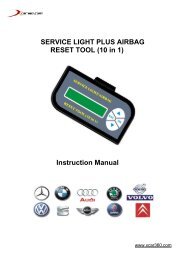
3. Using the Scan Tool3.1 Tool Description8
1 LCD DISPLAY -- Indicates test results. Backlit, 128 x 64 pixeldisplay with contrast adjustment.2 ENTER BUTTON -- Confirms a selection (or action) from amenu.3 ESC BUTTON -- Cancels a selection (or action) from a menuor returns to the menu. It is also used to setup the system or exit theDTC Lookup screen when pressed.456789LEFT SCROLL BUTTON -- When look up DTCdefinitions, moves to previous character and moves to previousscreens to view additional information on DTC definition coversmore than on screen. It is also used to update DTC library whenpressed.RIGHT SCROLL BUTTON -- When look up DTCdefinitions, moves to next character and moves to next screens toviews additional information when DTC definition covers morethan one screen.UP SCROLL BUTTON -- Moves up through menu andsubmenu items in menu mode. When more than one screen of datais retrieved, moves up through the current screen to the previousscreens for additional data.DOWN SCROLL BUTTON -- Moves down through menuand submenu items in menu mode. When more than one screen ofdata is retrieved, moves down through the current screen to nextscreens for additional data. It is also used as hotkey for languagesetup when pressed.HELP BUTTON -- Provides help information when pressed.POWER SWITCH -- Turns on/off the scan tool whenpowered by cell battery; reset the scanner when powered byvehicle battery.10 OBD II CONNECTOR -- Connects the scan tool to the vehicle’sData Link Connector (DLC).11 RUBBER BOOT -- Protects the scan tool from drop, abrasion andetc.9
3.2 Specifications1) Display: Backlit, 128 x 64 pixel display with contrast adjustment2) Operating Temperature: 0 to 60°C (32 to 140 F°)3) Storage Temperature: -20 to 70°C (-4 to 128 F°)4) External Power: 8.0 to 18.0 V power provided via vehicle battery5) Internal Power: 9V cell battery6) Dimensions:Length Width Height178 mm (7.00”) 95 mm (3.74”) 35 mm (1.38”)7) NW: 0.70 kg (1.54lb), GW: 1.0kg (2.20lb)3.3 Accessories Included1) User’s <strong>Manual</strong> -- Instructions on tool operations2) CD -- Includes user’s manual, DTC lookup software and etc.3) OBD2 cable -- Provides power to tool and communicates betweentool and vehicle4) USB cable -- Used to upgrade the scan tool.5) Carry case -- A nylon case to store the scan tool when not in use.6) Cell battery -- Supplies power to the scan tool whendisconnected from vehicle DLC.3.4 Navigation CharactersCharacters used to help navigate the scan tool are:1) “►” -- Indicates current selection.2) “ ”-- A DOWN Arrow indicates additional information isavailable on the next screen.3) “ ”-- An UP Arrow indicates additional information is availableon the previous screen.4) “$” -- Identifies the control module number from which the datais retrieved.5) “?” -- Indicates help information is available.10
6) “ ” -- Indicates battery volume.3.5 KeyboardNo solvents such as alcohol are allowed to clean the keypad or display.Use a mild nonabrasive detergent and a soft cotton cloth. Do not soakthe keypad as the keypad is not waterproof.3.6 PowerInternal Battery PowerThe scan tool has a 9V cell battery that provides power for off-carreviewing and analysis. Press the power key to turn on the scan tool.When the “ ” icon appears, replace the battery as instructed in“Battery Replacement” on paragraph 3.10.• If the scan tool is stored for a long period of time, removebatteries to prevent battery leakage from damaging batterycompartment.External PowerExternal power of the scan tool is provided via the vehicle Data LinkConnector (DLC). Just follow the steps below to turn on the scan tool:1) Connect the OBD II Cable to scan tool.2) Find DLC on vehicle.• A plastic DLC cover may be found for some vehicles and youneed to remove it before plugging the OBD2 cable.3) Plug OBD II cable to the vehicle’s DLC.3.7 Code LookupThe Code Lookup function is used to search for definitions ofDTCs in built-in DTC library.1) From Main Menu, use UP/DOWN scroll button to select DTCLookup and press ENTER button.11
Main Menu2/5Diagnostics►DTC LookupReview Data ?System SetupTool Information• The number “x/x” to the right indicates total number of itemsunder this menu and sequence of highlighted item.• The “?” to the right indicates help information available. PressHELP button to view information for selected item.2) From DTC Lookup menu, use LEFT/RIGHT arrow button tomove to the desired character, use UP/ DOWN arrow button tochange selected digit/character and press ENTER button toconfirm.DTC LookupP 0 0 0 1[ ] = Left, [ ] = Right[ ][ ]= Change Digit[ENTER]= Confirm[ESC]= Exit3) View the DTC definition on screen. When DTC definition coversmore than one screen, use LEFT/RIHT button to viewadditional information on previous/next screens.• For manufacturer specific codes, you need to select a vehiclemake on an additional screen to look for DTC definitions.• If definition could not be found (SAE or ManufacturerSpecific), the scan tool displays “DTC definition not found!Please refer to vehicle service manual!”4) To view next or previous DTC in the built-in DTC library, useUP/DOWN button.12
5) To enter another DTC, press ESC button to return to previousscreen.6) To exit to Main Menu, press ESC button.3.8 Product SetupThe scan tool allows you to make the following adjustments andsettings:1) Language: Selects desired language.2) Contrast adjustment: Adjusts the contrast of the LCD display.3) Unit of measure: Sets the unit of measure to English or Metric.4) Auto Power-off: Sets automatic power-off time limits.5) Beep Set: Turns on/off beep.6) Tool self-test: Tests the LCD display and the keyboard.• Settings of the unit will remain until change to the existingsettings is made.To enter the setup menu modeFrom the keyboard: Press ESC button to enter System Setup menu.Follow instructions to make adjustments and settings as described inthe following setup options.System Setup1/6► LanguageContrastUnit of Measure ?Auto Power-offBeep SetTool Self-testFrom Main Menu: Use UP/DOWN scroll button to select SystemSetup, and press ENTER button. Follow instructions to makeadjustments and settings as described in the following setup options.13
Main Menu4/5DiagnosticsDTC LookupReview Data ?►System SetupTool InformationLanguage Setup• English is the default language.1) From System Setup menu, use UP/DOWN scroll button to selectLanguage, and press ENTER button.System Setup1/6► LanguageContrastUnit of Measure ?Auto Power-offBeep SetTool Self-test2) Use UP/DOWN scroll button to select the desired language andpress ENTER button to save your selection and return toprevious menu.►EnglishFrançaisEspañolLanguage1/314
Contrast Adjustment1) From System Setup menu, use UP/DOWN scroll button to selectContrast, and press ENTER button.System Setup2/6Language► ContrastUnit of Measure ?Auto Power-offBeep SetTool Self-test2) From Contrast menu, use UP/DOWN scroll button to increase ordecrease contrast.Contrast(30%)Use or to change3) Press ENTER button to save your settings and return to previousmenu.Unit of Measurement• Metric is the default measurement unit.1) From System Setup menu, use UP/DOWN scroll button to selectUnit of Measure and press ENTER button.15
System Setup3/6LanguageContrast► Unit of Measure ?Auto Power-offBeep SetTool Self-test2) From Unit of Measure menu, use UP/DOWN scroll button toselect the desired unit of measurement.Unit of Measure2/2English► Metric ?3) Press ENTER button to save your selection and return to previousmenu.Auto Power-off• The minimum automatic power-off time is 1 minute, and themaximum is 20 minutes.• Automatic power-off setup function can be available only whenthe scanner is powered by cell battery.1) From System Setup menu, use UP/DOWN scroll button to selectAuto Power-off and press ENTER button.16
System Setup4/6LanguageContrastUnit of Measure ?► Auto Power-offBeep SetTool Self-test2) From Auto Power-off menu, use UP/DOWN scroll button toincrease or decrease time.Auto Power-off01 Minute[ ] – Increase time[ ] – Decrease time[ENTER] - Confirm3) Press ENTER button to save your setting and return to previousmenu.Beep Set• The default setting is Beep On.1) From System Setup menu, use UP/DOWN scroll button to selectBeep Set and press ENTER button.System Setup5/6LanguageContrastUnit of Measure ?Auto Power-off► Beep SetTool Self-test17
2) From Beep Set menu, use UP/DOWN scroll button to selectBeep ON or Beep OFF to turn on/off the beep.Beep Set2/2Beep ON►Beep OFF ?3) Press ENTER button to save your selection and return toprevious menu.Tool Self-testThe Tool Self-test function checks if the display and keyboard areworking properly.A. Display testThe Display Test function checks if the LCD display is workingnormally.1) From System Setup menu, use UP/DOWN scroll button to selectTool Self-Test, and press ENTER button.System Setup6/6LanguageContrastUnit of Measure ?Auto Power-offBeep Set► Tool Self-test2) Select Display Test from Tool Self-Test menu and press ENTERbutton.18
Tool Self-test1/2► Display TestKeyboard Test ?3) Press ENTER button again to start test. Look for missing spots inthe solid black characters.4) When completed, press ESC button to return.B. Keyboard TestThe Keyboard Test function verifies if the keys are workingproperly.1) Use UP/DOWN scroll button to select Keyboard Test from ToolSelf-test menu, and then press ENTER button.Tool Self-test2/2Display Test► Keyboard Test ?2) Press any key to start test. When you press a key, the key nameshould be observed on the display. If the key name does not showup, then the key is not working properly.19
Keyboard TestPress any key tostart testKey:Double [ESC] to return• If you press and hold the power switch, the key name doesnot show on the screen, but resets the scanner when poweredby vehicle battery, or turns off the scanner when powered bycell battery. If it does not restart the scanner or power off thescanner, the key is not working properly.3) Double press ESC to return to previous menu.3.9 Tool InformationThe Tool Information function allows viewing of some importantinformation such as serial number and software version numberof the scan tool.1) From Main Menu, use UP/DOWN scroll button to select ToolInformation and press ENTER button.Main Menu5/5DiagnosticsDTC LookupReview Data ?System Setup►Tool Information2) View tool information on screen.20
Tool InformationSerial No. : M4083462Burn Date: 12/03/07S/W Ver : V1.00H/W Ver : V1.10LIB Ver : V1.003.10 Battery ReplacementThe scan tool requires a 9V cell battery to operate when disconnectedfrom vehicle power. When the icon appears on the screen, replacethe battery.1) Locate the battery cover on the back of the scan tool.2) Remove the battery cover screw and slide the battery cover off.3) Remove discharged batteries and install a new 9V cell battery.4) Reinstall battery cover by sliding battery cover on and installingscrew.3.11 Vehicle CoverageThe Maxiscan TM <strong>MS409</strong> OBDII/EOBD Scanner is specially designedto work with all OBD II compliant vehicles, including those equippedwith next-generation protocol -- Control Area Network (CAN). It isrequired by EPA that all 1996 and newer vehicles (cars and light trucks)sold in the United States must be OBD II compliant and this includesall Domestic, Asian and European vehicles.A small number of 1994 and 1995 model year gasoline vehicles areOBD II compliant. To verify if a 1994 or 1995 vehicle is OBD IIcompliant, check the Vehicle Emissions Control Information (VECI)Label which is located under the hood or by the radiator of mostvehicles. If the vehicle is OBD II compliant, the label will designate“OBD II Certified”. Additionally, Government regulations mandatethat all OBD II compliant vehicles must have a “common” sixteen-pinData Link Connector (DLC).21
For your vehicle to be OBD II compliant it must have a 16-pin DLC(Data Link Connector) under the dash and the Vehicle EmissionControl Information Label must state that the vehicle is OBD IIcompliant.3.12 Product TroubleshootingVehicle Linking ErrorA communication error occurs if the scan tool fails to communicatewith the vehicle’s ECU (Engine Control Unit). You need to do thefollowing to check up:Verify that the ignition is ON;Check if the scan tool’s OBD II connector is securely connected tothe vehicle’s DLC;Verify that the vehicle is OBD2 compliant;Turn the ignition off and wait for about 10 seconds. Turn theignition back to on and continue the testing.Verify the control module is not defective.Operating ErrorIf the scan tool freezes, then an exception occurs or the vehicle’s ECU(Engine Control Unit) is too slow to respond to requests. You need todo the following to reset the tool:Press and hold POWER button for at least 2 seconds to reset thescan tool.Turn the ignition off and wait for about 10 seconds. Turn theignition back to on and continue the testing.Scan tool doesn’t power upIf the scan tool won’t power up or operates incorrectly in any otherway, you need to do the following to check up:Check if the scan tool’s OBD II connector is securely connected tothe vehicle’s DLC;22
Check if the DLC pins are bent or broken. Clean the DLC pins ifnecessary.Check vehicle battery to make sure it is still good with at least 8.0volts.4. Review DataThe Review Data function allows viewing of recorded data fromlast vehicle test.1) Use UP/DOWN scroll button to select Review Data from MainMenu, and press ENTER buttonMain Menu3/5DiagnosticsDTC Lookup►Review Data ?System SetupTool Information2) Use UP/DOWN scroll button to select the desired item fromReview Data menu, and press ENTER button.Review Data1/5►Stored CodesPending CodesFreeze Frame ?I/M ReadinessVehicle Info.• If there is no data stored for selected item, a “Not Supportedor Stored No Data!” message shows on the screen.3) Review selected data on screen.23
P0118$09 1/6GenericEngine Coolant TemperatureSensor 1 Circuit High5. OBD II DiagnosticsWhen more than one vehicle control module is detected by thescan tool, you will be prompted to select the module where thedata may be retrieved. The most often to be selected are thePowertrain Control Module [PCM] and Transmission ControlModule [TCM].CAUTION: Don’t connect or disconnect any test equipment withignition on or engine running.1) Turn the ignition off.2) Locate the vehicle’s 16-pin Data Link Connector (DLC).3) Plug into the scan tool cable connector to the vehicle’s DLC.4) Turn the ignition on. Engine can be off or running.5) Press ENTER button to enter Main Menu. Use UP/DOWNscroll button to select Diagnostics from the menu.Main Menu1/5► DiagnosticsDTC LookupReview Data ?System SetupTool Information24
6) Press ENTER button to confirm. A sequence of messagesdisplaying the OBD2 protocols will be observed on the displayuntil the vehicle protocol is detected.• If the scan tool fails to communicate with the vehicle’s ECU(Engine Control Unit), a “LINKING ERROR!” messageshows up on the display.Verify that the ignition is ON;Check if the scan tool’s OBD II connector is securelyconnected to the vehicle’s DLC;Verify that the vehicle is OBD2 compliant;Turn the ignition off and wait for about 10 seconds. Turn theignition back to on and repeat the procedure from step 5.• If the “LINKING ERROR” message does not go away, thenthere might be problems for the scan tool to communicatewith the vehicle. Contact your local distributor or themanufacturer’s customer service department for assistance.7) You will be prompted to erase previously stored data.• Review previously stored data thoroughly before erasing.DiagnosticErase previouslystored data to savedata from this test?YESNO• If no data is stored in the scan tool, above prompt will notshow up.8) If you wish to erase the data, press ENTER button; if you do notwant to erase the data, press ESC or use LEFT/RIGHT button toselect NO and press ENTER to continue.25
9) View a summary of system status (MIL status, DTC counts,Monitor status) on screen. Wait a few seconds or press any keyfor Diagnostic Menu to come up.System StatusMIL StatusONCodes Found 6Readiness Complete NFreeze Data ExistYPress any key to con.• If more than one module is detected, you will be prompted toselect a module before testing.Control Module1/2► EngineModule $A4 ?• Use UP/DOWN scroll button to select a module and pressENTER button.5.1 Reading Codesu Reading Codes can be done with the key on engine off (KOEO)or with the key on engine running (KOER).u Stored Codes are also known as “hard codes” or “permanentcodes”. These codes cause the control module to illuminate themalfunction indicator lamp (MIL) when emission-related faultoccurs.u Pending Codes are also referred to as “maturing codes” or“continuous monitor codes”. They indicate problems that the26
control module has detected during the current or last drivingcycle but are not considered serious yet. Pending Codes will notturn on the malfunction indicator lamp (MIL). If the fault doesnot occur within a certain number of warm-up cycles, the codeclears from memory.1) Use UP/DOWN scroll button to select Read Codes fromDiagnostic Menu and press ENTER button.Diagnostic Menu1/6► Read CodesErase CodesView Freeze Frame ?I/M ReadinessVehicle Info.Unit of Measure2) Use UP/DOWN scroll button to select Stored Codes or PendingCodes from the Trouble Codes menu and press ENTER button.Trouble Codes1/2►Stored CodesPending Codes ?• If there are no Diagnostic Trouble Codes present, the displayindicates “No (pending) codes are stored in the module!”Wait a few seconds or press any key to return to DiagnosticMenu.3) View DTCs and their definitions on screen.27
P0118$09 1/5GenericEngine Coolant TemperatureSensor 1 Circuit High• The control module number, sequence of the DTCs, totalnumber of codes detected and type of codes (Generic orManufacturer specific) will be observed on the upper righthand corner of the display.4) If more than one DTC is found, use UP/DOWN scroll button, asnecessary, until all the codes have been shown up.• If retrieved DTCs contain any manufacturer specific orenhanced codes, a “Manufacturer specific codes are found!Press any key to select vehicle make!” message comes upprompting you to select vehicle manufacturer to view DTCdefinitions. Use UP/DOWN scroll button to selectmanufacturer and then press ENTER button to confirm.Vehicle Manufacturer1/51►Alfa RomeoAudi/VWBMW ?BuickCadillacChevrolet• If the manufacturer for your vehicle is not listed, useUP/DOWN scroll button to select Other and press ENTERbutton.28
5.2 Erasing CodesCAUTION: Erasing the Diagnostic Trouble Codes may allow thescan tool to delete not only the codes from the vehicle’s on-boardcomputer, but also “Freeze Frame” data and manufacturer specificenhanced data. Further, the I/M Readiness Monitor Status for allvehicle monitors is reset to Not Ready or Not Complete status. Do noterase the codes before the system has been checked completely by atechnician.u This function is performed with key on engine off (KOEO). Donot start the engine.1) Use UP/DOWN scroll buttons to select Erase Codes fromDiagnostics Menu and press ENTER button.Diagnostic Menu2/6► Read CodesErase CodesView Freeze Frame ?I/M ReadinessVehicle Info.Unit of Measure2) A warning message comes up asking for your confirmation.Erase CodesErase trouble codes!Are you sure?YESNO• If you do not want to proceed with erasing codes, press ESCbutton or use LEFT/RIGHT scroll button to select NO to exit.A message of “Command Cancelled!” show ups. Wait a fewseconds or press any key to return to Diagnostic Menu.29
3) Press ENTER button to confirm.• If the codes are cleared successfully, an “Erase Done!”confirmation message shows on the display.Erase CodesErase Done!Press any key to con.• If the codes are not cleared, then an “Erase Failure. Turn Keyon with Engine off!” message appears.Erase CodesErase Failure.Turn Key on withEngine Off!Press any key to con.Press any key to con.4) Press any button to return to Diagnostic Menu.5.3 Viewing Freeze Frame Data1) To view freeze frame data, use UP/DOWN scroll button to selectView Freeze Frame from Diagnostic Menu and press ENTERbutton.30
• Oxygen Sens Mon -- O2 Sensors Monitor• Catalyst Mon -- Catalyst Monitor• EVAP System Mon -- Evaporative System Monitor• Oxygen Sens htr -- O2 Sensor Heater Monitor• Sec Air System -- Secondary Air Monitor• Htd Catalyst -- Heated Catalyst Monitor• A/C Refrig Mon -- A/C system Monitor…………Since DTCs Cleared… ………MIL StatusMisfire MonitorFuel System MonComp. ComponentCatalyst MonHtd CatalystOFFOKOKOKINCN/A5) If the vehicle supports readiness test of “This Drive Cycle”, ascreen of the following displays:…………..This Drive Cycle…… ……….MIL StatusMisfire MonitorFuel System MonComp. ComponentCatalyst MonHtd CatalystOFFOKN/AOKINCN/A6) Press ESC button to return to Diagnostic Menu.5.5 Viewing Vehicle InformationThe Vehicle Info. function enables retrieval of VehicleIdentification No. (VIN), Calibration ID Nos. (CINs), CalibrationVerification Nos. (CVNs) and In-use Performance Tracking on2000 and newer vehicles that support Mode 9.34
1) Use UP/DOWN scroll button to select Vehicle Info. from theDiagnostic Menu and press ENTER button...........Diagnostic Menu..... ........5/6Read CodesErase CodesView Freeze Frame ?I/M Readiness► Vehicle Info.Unit of Measure2) Observe on-screen instruction.Vehicle Info.Turn key onwith engine off !Press any key to con.3) Wait a few seconds while the scan tool reads vehicle information.………………Vehicle Info.Reading Info…- Please Wait -• If the vehicle does not support this mode, a message shows onthe display warning that the mode is not supported.4) From Vehicle Info. menu, use UP/DOWN scroll button to selectan available items and press ENTER button.35
……………..Vehicle Info.2/3Vehicle ID Number►Calibration ID No.Cal. Verif. Number ?5) View the vehicle information retrieved.……………Calibration ID………………..Cal ID1:LMC720………..6) Press ESC button to return previous menu.36
6. Appendix6.1 Appendix 1-- PID ListPID AbbreviationFull NameDTC_CNTDTC Stored NumberDTCFRZFDTCFUELSYS1Fuel System 1 StatusFUELSYS2Fuel System 2 StatusLOAD_PCT (%) Calculated Load ValueETC(°F)Engine Coolant TemperatureETC(°C)Engine Coolant TemperatureSHRTFT1 (%)Short Term Fuel Trim-Bank1SHRTFT3 (%)Short Term Fuel Trim-Bank3LONGFT1 (%)Long Term Fuel Trim-Bank1LONGFT3 (%)Long Term Fuel Trim-Bank3SHRTFT2 (%)Short Term Fuel Trim-Bank2SHRTFT4 (%)Short Term Fuel Trim-Bank4LONGFT2 (%)Long Term Fuel Trim-Bank2LONGFT4 (%)Long Term Fuel Trim-Bank4FRP(kPa)Fuel Rail Pressure(gauge)FRP(psi)Fuel Rail Pressure(gauge)MAP(kPa)Intake Manifold Absolute PressureMAP(inHg)Intake Manifold Absolute PressureRPM(/min)Engine RPMVSS(km/h)Vehicle Speed SensorVSS(mph)Vehicle Speed SensorSPARKADV(\x82) Ignition Timing Advance for #1IAT(°F)Intake Air TemperatureIAT(°C)Intake Air TemperatureMAF(g/s)Mass Air Flow SensorMAF(lb/min)Mass Air Flow Sensor37
PID AbbreviationTP (%)AIR_STATO2SLOCO2B1S1(V)SHRTFTB1S1 (%)O2B1S2(V)SHRTFTB1S2 (%)O2B1S3(V)SHRTFTB1S3 (%)O2B1S4(V)SHRTFTB1S4 (%)O2B2S1(V)SHRTFTB2S1 (%)O2B2S2(V)SHRTFTB2S2 (%)O2B2S3(V)SHRTFTB2S3 (%)O2B2S4(V)SHRTFTB2S4 (%)O2B1S1(V)SHRTFTB1S1 (%)O2B1S2(V)SHRTFTB1S2 (%)O2B2S1(V)SHRTFTB2S1 (%)O2B2S2(V)SHRTFTB2S2 (%)O2B3S1(V)SHRTFTB3S1 (%)O2B3S2(V)SHRTFTB3S2 (%)Full NameAbsolute Throttle PositionCommanded Secondary Air StatusLocation of O2 SensorsO2 Sensor Output Voltage(B1S1)Short Term Fuel Trim(B1S1)O2 Sensor Output Voltage(B1S2)Short Term Fuel Trim(B1S2)O2 Sensor Output Voltage(B1S3)Short Term Fuel Trim(B1S3)O2 Sensor Output Voltage(B1S4)Short Term Fuel Trim(B1S4)O2 Sensor Output Voltage(B2S1)Short Term Fuel Trim(B2S1)O2 Sensor Output Voltage(B2S2)Short Term Fuel Trim(B2S2)O2 Sensor Output Voltage(B2S3)Short Term Fuel Trim(B2S3)O2 Sensor Output Voltage(B2S4)Short Term Fuel Trim(B2S4)O2 Sensor Output Voltage(B2S1)Short Term Fuel Trim(B2S1)O2 Sensor Output Voltage(B1S2)Short Term Fuel Trim(B1S2)O2 Sensor Output Voltage(B2S1)Short Term Fuel Trim(B2S1)O2 Sensor Output Voltage(B2S2)Short Term Fuel Trim(B2S2)O2 Sensor Output Voltage(B3S1)Short Term Fuel Trim(B3S1)O2 Sensor Output Voltage(B3S2)Short Term Fuel Trim(B3S2)38
PID AbbreviationO2B4S1(V)SHRTFTB4S1 (%)O2B4S2(V)SHRTFTB4S2 (%)OBDSUPO2SLOCRUNTM(sec)MIL_DIST(km)MIL_DIST(mile)FRP(kPa)FRP(PSI)FRP(kPa)FRP(PSI)EQ_RATB1S1O2B1S1(V)EQ_RATB1S2O2B1S2(V)EQ_RATB1S3O2B1S3(V)EQ_RATB1S4O2B1S4(V)EQ_RATB2S1O2B2S1(V)EQ_RATB2S2O2B2S2(V)EQ_RATB2S3O2B2S3(V)EQ_RATB2S4O2B2S4(V)EQ_RATB1S1Full NameO2 Sensor Output Voltage(B4S1)Short Term Fuel Trim(B4S1)O2 Sensor Output Voltage(B4S2)Short Term Fuel Trim(B4S2)OBD Require To Which Vehicle DesignedLocation of O2 SensorsTime Since Engine StartDistance Traveled While MIL ActivatedDistance Traveled While MIL ActivatedFuel Rail Pres. Relative To Manifold VacuumFuel Rail Pres. Relative To Manifold VacuumFuel Rail PressureFuel Rail PressureEquivalence Ratio(wide range O2S)(B1S1)O2 Sensor Voltage(wide range O2S)(B1S1)Equivalence Ratio(wide range O2S)(B1S2)O2 Sensor Voltage(wide range O2S)(B1S2)Equivalence Ratio(wide range O2S)(B1S3)O2 Sensor Voltage(wide range O2S)(B1S3)Equivalence Ratio(wide range O2S)(B1S4)O2 Sensor Voltage(wide range O2S)(B1S4)Equivalence Ratio(wide range O2S)(B2S1)O2 Sensor Voltage(wide range O2S)(B2S1)Equivalence Ratio(wide range O2S)(B2S2)O2 Sensor Voltage(wide range O2S)(B2S2)Equivalence Ratio(wide range O2S)(B2S3)O2 Sensor Voltage(wide range O2S)(B2S3)Equivalence Ratio(wide range O2S)(B2S4)O2 Sensor Voltage(wide range O2S)(B2S4)Equivalence Ratio(wide range O2S)(B2S1)39
O2B1S1(V)O2 Sensor Voltage(wide range O2S)(B2S1)40
PID AbbreviationEQ_RATB1S2O2B1S2(V)EQ_RATB2S1O2B2S1(V)EQ_RATB2S2O2B2S2(V)EQ_RATB3S1O2B3S1(V)EQ_RATB3S2O2B3S2(V)EQ_RATB4S1O2B4S1(V)EQ_RATB4S2O2B4S2(V)EGR_PTC (%)EGR_ERR (%)EVAP_PCT (%)FLI (%)WARM_UPSCLR_DIST(km)CLR_DIST(mile)EVAP_VP(Pa)EVAP_VP(inH2O)BARO(kPa)BARO(inHg)EQ_RAT11O2S11(mA)EQ_RAT12O2S12(mA)EQ_RAT13Full NameEquivalence Ratio(wide range O2S)(B1S2)O2 Sensor Voltage(wide range O2S)(B1S2)Equivalence Ratio(wide range O2S)(B2S1)O2 Sensor Voltage(wide range O2S)(B2S1)Equivalence Ratio(wide range O2S)(B2S2)O2 Sensor Voltage(wide range O2S)(B2S2)Equivalence Ratio(wide range O2S)(B3S1)O2 Sensor Voltage(wide range O2S)(B3S1)Equivalence Ratio(wide range O2S)(B3S2)O2 Sensor Voltage(wide range O2S)(B3S2)Equivalence Ratio(wide range O2S)(B4S1)O2 Sensor Voltage(wide range O2S)(B4S1)Equivalence Ratio(wide range O2S)(B4S2)O2 Sensor Voltage(wide range O2S)(B4S2)Commanded EGREGR ErrorCommanded Evaporative PurgeFuel Level InputNumber of Warm-ups Since DTC ClearedDistance Since DTC ClearedDistance Since DTC ClearedEvap System Vapor PressureEvap System Vapor PressureBarometric PressureBarometric PressureEquivalence Ratio(wide range O2S)(B1S1)O2 Sensor Current(wide range O2S)(B1S1)Equivalence Ratio(wide range O2S)(B1S2)O2 Sensor Current(wide range O2S)(B1S2)Equivalence Ratio(wide range O2S)(B1S3)41
O2S13(mA)O2 Sensor Current(wide range O2S)(B1S3)PID AbbreviationEQ_RAT14Full NameEquivalence Ratio(wide range O2S)(B1S4)删 除 的 内 容 :分 页 符O2S14(mA)O2 Sensor Current(wide range O2S)(B1S4)EQ_RAT21Equivalence Ratio(wide range O2S)(B2S1)O2S21(mA)O2 Sensor Current(wide range O2S)(B2S1)EQ_RAT22Equivalence Ratio(wide range O2S)(B2S2)O2S22(mA)O2 Sensor Current(wide range O2S)(B2S2)EQ_RAT23Equivalence Ratio(wide range O2S)(B2S3)O2S23(mA)O2 Sensor Current(wide range O2S)(B2S3)EQ_RAT24Equivalence Ratio(wide range O2S)(B2S4)O2S24(mA)O2 Sensor Current(wide range O2S)(B2S4)EQ_RAT11Equivalence Ratio(wide range O2S)(B2S1)O2S11(mA)O2 Sensor Current(wide range O2S)(B2S1)EQ_RAT12Equivalence Ratio(wide range O2S)(B1S2)O2S12(mA)O2 Sensor Current(wide range O2S)(B1S2)EQ_RAT21Equivalence Ratio(wide range O2S)(B2S1)O2S21(mA)O2 Sensor Current(wide range O2S)(B2S1)EQ_RAT22O2S22(mA)Equivalence Ratio(wide range O2S)(B2S2)O2 Sensor Current(wide range O2S)(B2S2)EQ_RAT31Equivalence Ratio(wide range O2S)(B3S1)O2S31(mA)O2 Sensor Current(wide range O2S)(B3S1)EQ_RAT32Equivalence Ratio(wide range O2S)(B3S2)O2S32(mA)O2 Sensor Current(wide range O2S)(B3S2)EQ_RAT41Equivalence Ratio(wide range O2S)(B4S1)O2S41(mA)O2 Sensor Current(wide range O2S)(B4S1)EQ_RAT42O2S42(mA)Equivalence Ratio(wide range O2S)(B4S2)O2 Sensor Current(wide range O2S)(B4S2)CATEMP11(°F)Catalyst Temperature Bank1Sensor1CATEMP11(°C)CATEMP21(°F)Catalyst Temperature Bank1Sensor1Catalyst Temperature Bank2Sensor142
CATEMP21(°C)CATEMP12(°F)Catalyst Temperature Bank2Sensor1Catalyst Temperature Bank1Sensor243
PID AbbreviationCATEMP12(°C)CATEMP22(°F)CATEMP22(°C)VPWR(V)LOAD_ABS (%)EQ_RATTP_R (%)AAT(°F)AAT(°C)TP_B (%)TP_C (%)APP_D (%)APP_E (%)APP_F (%)TAC_PCT (%)MIL_TIMECLR_TIMEFull NameCatalyst Temperature Bank1Sensor2Catalyst Temperature Bank2Sensor2Catalyst Temperature Bank2Sensor2Control Module VoltageAbsolute Load ValueCommanded Equivalence RatioRelative Throttle PositionAmbient Air TemperatureAmbient Air TemperatureAbsolute Throttle Position BAbsolute Throttle Position CAccelerator Pedal Position DAccelerator Pedal Position EAccelerator Pedal Position FCommanded Throttle Actuator ControlMinute run by Engine While MIL activatedTime since Diagnostic Trouble Code Clear44
7. Warranty and Service7.1 Limited One Year WarrantyAutel warrants to its customers that this product will be free from alldefects in materials and workmanship for a period of one (1) year fromthe date of the original purchase, subject to the following terms andconditions:1) The sole responsibility of Autel under the Warranty is limited toeither the repair or, at the option of Autel, replacement of the scantool at no charge with Proof of Purchase. The sales receipt may beused for this purpose.2) This warranty does not apply to damages caused by improper use,accident, flood, lightning, or if the product was altered or repairedby anyone other than the Manufacturer’s Service Center.3) Autel shall not be liable for any incidental or consequentialdamages arising from the use, misuse, or mounting of the scan tool.Some states do not allow limitations on how long an impliedwarranty lasts, so the above limitations may not apply to you.4) All information in this manual is based on the latest informationavailable at the time of publication and no warranty can be madefor its accuracy or completeness. Autel reserves the right to makechanges at any time without notice.7.2 Service ProceduresIf you have any questions, please contact your local store, distributor orvisit our website at www.auteltech.com.If it becomes necessary to return the scan tool for repair, contact yourlocal distributor for more information.45