Material Cross Reference Table
Material Cross Reference Table
Material Cross Reference Table
- No tags were found...

You also want an ePaper? Increase the reach of your titles
YUMPU automatically turns print PDFs into web optimized ePapers that Google loves.
Technical InformationR1~R40General InformationSI Unit Conversion <strong>Table</strong> / Cutting SymbolSurface RoughnessHeat Treatment and Hardness ExpressionVickers Hardness Conversion Chart<strong>Material</strong> List (JIS)<strong>Material</strong> <strong>Cross</strong> <strong>Reference</strong> <strong>Table</strong>Various <strong>Cross</strong> <strong>Reference</strong> <strong>Table</strong>sInsert <strong>Cross</strong> <strong>Reference</strong> <strong>Table</strong>Molded Chipbreaker <strong>Cross</strong> <strong>Reference</strong> <strong>Table</strong>Milling Insert Description <strong>Cross</strong> <strong>Reference</strong> <strong>Table</strong>Trouble shootingCutting Edge Figuration and CountermeasuresTurningMillingDrillingTerms and Angles of ToolholderTerms and Angles of Turning ToolholderTerms and Angles of Milling CutterBasic FormulasBasic Formulas (Turning)Basic Formulas (Milling / Drilling)Tooling Examples of Small ToolsTooling ExamplesAutomatic Lathe List by ManufacturerR2~R15R2R3R4R5R6R7R16~R23R16R21R22R24~R27R24R25R26R27R28~R29R28R29R30~R33R30R32R34~R40R34R36R1
SI Unit Conversion <strong>Table</strong> / Cutting SymbolSI Derived Units Conversion Chart(Bold lined units are the ones by SI Derived Unit.)ForceN kgf dyn19.806 651×10 -5 1.019 72×10 -111.019 72×10 -6 1×10 59.806 65×10 51Extracted from JIS Handbook “Steel”Stress 1Pa=1N/m 2 ,1MPa=1N/mm 2Pa or N/m 2 MPa or N/mm 2 kgf/mm 2 kgf/cm 2 kgf/m 211×10 69.806 65×10 69.806 65×10 49.806 651×10 -619.806 659.806 65×10 -29.806 65×10 -6 1.019 72×10 - 71.019 72×10 - 111×10 - 21×10 - 61.019 72×10 - 51.019 72×101×10 211×10 - 41.019 72×10 -11.019 72×10 51×10 61×10 41Pressure 1Pa=1N/m 2Pa kPa Mpa bar kgf/cm 211×10 31×10 61×10 59.806 65×10 4 1×10 -311×10 31×10 29.806 65×101×10 -61×10 -311×10 -19.806 65×10 -2 1×10 -51×10 -21×1019.806 65×10 -1 1.019 72×10 -51.019 72×10 -21.019 72×101.019 721Symbols of cutting conditionsCutting conditions below are indicated by the new symbols listed in 2nd column.1) Turning3) DrillingCutting ConditionNew symbol(Previous symbol)UnitCutting ConditionNew symbol(Previous symbol)UnitCutting speedVcVm/minCutting speedVcVm/minFeed rateffmm/revFeed speedVfFmm/minDepth of cutapdmmFeed rateffmm/revEdge widthWWmmDrill diameterDcD (Ds)mmWorkpiece diameterDmDmmPower required at spindlePcPkwkWPower required at spindlePcPkwkWSpecific cutting resistancekcKsMPaSpecific cutting resistancekcKsMPaDepth of holeHdmmTheoretical surface roughnesshRzμmRevolutionnNmin -1RCorner radiusRevolutionNote: 'rε' is read as 'r epsilon'rεnRNmmmin -12) MillingCutting ConditionNew symbol(Previous symbol)UnitTechnicalInformationCutting speedFeed speedFeed per toothFeed rateVcVffzfVFffm/minmm/minmm/tmm/revNumber of insertsZZteethDepth of cutapdmmWidth of cutaewmmPick feedPfPfmmPower required at spindlePcPkwkWSpecific cutting resistancekcKsMPaMetal Removal RateQQcm 3 /minRevolutionnNmin -1R2
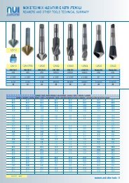
Surface Roughness (JIS B 0601-2001) Theoretical (Geometrical) Surface RoughnessTheoretical Surface Roughness at Turning indicates the minimumroughness value from the cutting conditions and it is shown by theformula as follows:f2fRz(h) ×10 38R(rε)Rz(h)Theoretical Surface RoughnessμmFeed Ratemm/rev(rε)Corner Radius of InsertmmRRz(h)How to Obtain Surface Roughness ValuesType SymbolMax. HeightRoughnessTen Points MeanRoughnessArithmetical MeanRoughnessRzRzJISRaHow to ObtainRy is obtained from the distance in micronmeter between the highest peak and thelowest valley in the range of sampledreference length (l) to the direction of meanline of the roughness curve.RzRpRvRz is obtained from the total in micron meterof the mean value of the each distancebetween the mean line and 5 peaks (Yp)from the highest one, and the mean value ofthe each distance between the mean lineand the 5 valleys (Yv) from the lowest one,of the roughness curve in the range ofsampled reference length “l”.RzJIS Yp1Yp2Yp3Yp4Yp5Yv1Yv2Yv3Yv4Yv55Ra is obtained from the following formula inmicron meter when the roughness curve isexpressed by y=f(x), taking X-axis to the meanline direction and Y-axis to the verticalmagnification of the roughness curve in therange of sampled reference length “l”.1 lRa ∫ f(x)dxl 0ExplanationYp1,Yp2,Yp3,Yp4,Yp5:Distance from the mean line to highest 5peaks in the range of sampled referencelength “l”Yv1,Yv2,Yv3,Yv4,Yv5:Distance from the mean line to the lowest 5valleys in the range of sampled referencelength “l”RaYYp1Yv1RpYp2mYv2RyYp3Yv3Yp4RvYv4Yv5mYv5mXRelationship with Triangle SymbolArithmeticalMean RoughnessRa(μm)0.0250.050.10.20.40.81.63.26.312.525Max. HeightRoughnessRz(μm)0.10.20.40.81.63.26.312.52550100Ten PointsMeanRoughnessRzJIS(μm)0.10.20.40.81.63.26.312.52550100Note: Finishing symbol (Triangleand wave~) wasabolished from JIS standard from 1994 Revision.How to IndicateExampleWhen Ra is 1.6μm→1.6μmRaWhen Rz is 6.3μm→6.3μmRzWhen RzJIS is 6.3μm→6.3μmRzJISNote:(Relationshipwith Triangle)Indication in JIS StandardExample of Ra IndicationWhen indicating the upper limit only(when upper limit is 6.3μmRa)Example of Ry, (Rz) Indication6.3When indicating upper limit onlyIndicatesurface roughness following the parametersymbol.Rz6.3RWhen indicating both lower and upper limit(when upper limit is 6.3μmRa, lower limit is 1.6μmRa)Note: The indications of Ra and Rz are different.6.31.6 Surface Roughness Symbol CautionWhen indicating both lower and upper limitIndicate surface roughness as (upper limit ~lower limit) following the parameter symbol.Rz6.3~1.6TechnicalInformationThe above information is based on JIS B 0601-2001.However, some symbols were revised as shown in the right table inaccordance with ISO Standard from JIS B 0601-2001 version.Ten Points Mean Roughness (Rz) was eliminated from 2001 versionbut it still remains as RzJIS reference, since it was popular in Japan.TypeMax. HeightRoughnessTen PointsMean RoughnessArithmetical MeanRoughnessSymbol ofJIS B 0601-1994RyRzRa→→→Symbol ofJIS B 0601-2001RzRzJISRaR3
Heat Treatment and Hardness ExpressionHeat TreatmentOne of the ways to determine the hardness of steel is the heat treatment and it is classified to 3 types.Heat TreatmentQuenching (Tempering)NormalizingAnnealingTemperature727°C600°C550°CRapidlySlowlyVery Slowly SlowlyQuenching(Tempering)NormalizingAfter heating to over 727°C, cool rapidlydown to 550°C in water or oil.After heating to over 727°C, cool down rapidly to600°C and then to normal temperature.Quenching makes steel hard because it cools down red-hotsteel very rapidly in water or oil, but it may promote internalstress. In order to remove such internal stress, tempering isused.(After cooled down once, reheat it to 200°C~600°C)It miniaturizes the crystals. (Steel is also composed of smallcells.) It is used to improve the mechanical character ormachinability.TimeHeat Treatment MethodAnnealingAfter heating to over 727°C, cool down veryslowly to 600°C, then to normal temperature.It miniaturizes the crystals like the process of normalizing, butthe crystal size is bigger than that of normalizing.It targets machinability improvement and distortion correction.Hardness ValueHardness<strong>Reference</strong> Standard Example Explanation of ExampleBrinell HardnessJISZ22431992250HB200~250HBHardness Value : 250, Hardness Symbol : HBWhen the hardness has the rangeVickers HardnessJISZ22441998640HVHardness Value : 640, Hardness Symbol : HVRockwell HardnessJISZ2245199260HRCHardness Value : 60, Hardness Symbol : HRCShore HardnessJISZ2246199250HSHardness Value : 50, Hardness Symbol : HSRTechnicalInformationRather RapidlyR4
Vickers Hardness Conversion ChartVickers Hardness (HV)Brinell Hardness10mm Dia. BallLoad: 3000kgf(HB)Standard BallTungstenCarbideBallA ScaleLoad: 60kgfDiamondPoint(HRA)Rockwell HardnessB ScaleLoad: 100kgf1.6mmDia. Ball(HRB)(2)C ScaleLoad: 150kgfDiamondPoint(HRC)Shore Hardness (HS)(1)Tensile Strength MpaVickers Hardness (HV)Brinell Hardness10mm Dia. BallLoad: 3000kgf(HB)Standard BallTungstenCarbideBallA ScaleLoad: 60kgfDiamondPoint(HRA)Rockwell HardnessB ScaleLoad: 100kgf1.6mmDia. Ball(HRB)(2)C ScaleLoad: 150kgfDiamondPoint(HRC)Shore Hardness (HS)(1)Tensile Strength Mpa94092090088086085.685.385.084.784.468.067.567.066.465.932031030029529030329428428027530329428428027584082080078076084.183.883.483.082.665.364.764.063.362.528528027527026527026526125625227026526125625274072070069068082.281.881.381.180.861.861.060.159.759.226025525024524024724323823322824724323823322867066065064063080.680.380.079.879.558.858.357.857.356.823022021020019021920920019018121920920019018162061060059058079.278.978.678.478.056.355.755.254.754.12055202018017016015014017116215214313317116215214313357056055054053077.877.477.076.776.453.653.052.351.751.119851950190518601825130120110100951241141059590124114105959052051050049048076.175.775.374.974.550.549.849.148.447.717951750170516601620908586818681Extracted from JIS Handbook “Iron & Steel” (SAE J 417)Note (1) 1MPa = 1N/mm²(2) Value in ( ) is not in practical use, but reference onlyR47046045044043042041040039038074.173.673.372.872.371.871.470.870.369.846.946.145.344.543.642.741.840.839.838.81570153014951460141013701330129012401205TechnicalInformation37036035034033069.268.768.167.667.037.736.635.534.433.311701130109510701035R5
RTechnicalInformationSpecial Steel<strong>Material</strong> List (JIS) MetalClassification Name of JIS Standard SymbolRolled Steel for Welded Structure SMRe-Rolled SteelSRBStructuralRolled Steel for General Structure SSSteelLight Guage Steel for General Structure SSCHot-Rolled Steel Plate, Sheet and Strip for Automobile Structural Use SAPHSteel Cold-Rolled Steel Plate, Sheet and Strip SPCSheet Hot-Rolled Soft Steel Plate, Sheet and Strip SPHCarbon Steel Pipe for Ordinary Piping SGPCarbon Steel Pipe for Boiler / Heat Exchanger STBSeamless Steel Pipe for High Pressure Gas Cylinder STHCarbon Steel Pipe for General Structural Use STKCarbon Steel Pipe for Machine Structural Use STKMAlloy Steel Pipe for Structural Use STKSSteelStainless Steel Pipe for Machine Structural Use SUS-TKPipeSteel Square Pipe for General Structural Use STKRAlloy Steel Pipe for Ordinary Piping STPACarbon Steel Pipe for Pressure Service STPGCarbon Steel Pipe for High-Temperature Service STPTCarbon Steel Pipe for High-Pressure Service STSStainless Steel Pipe for Ordinary Piping SUS-TPCarbon Steel for Machine Structural Use SxxC, SxxCKAluminium Chromium Molybdenum Steel SACMSteel forChromium Molybdenum SteelSCMMachineChromium SteelSCrStructuralNickel Chromium SteelSNCUseNickel Chromium Molybdenum Steel SNCMManganese Steel and Manganese Chromium Steel for Machine Structural Use SMn, SMnCCarbon Tool SteelSKHollow Drill SteelSKCAlloy Tool SteelSKS, SKD, SKTHigh Speed Tool SteelSKHFree Cutting Carbon SteelSUMHigh Carbon Chromium Bearing Steel SUJSpring SteelSUPStainless Steel BarSUS-BHot-Rolled Stainless Steel Plate, Sheet and Strip SUS-HP, SUS-HSCold-Rolled Stainless Steel Plate, Sheet and Strip SUS-CP, SUS-CSTool SteelSpecialSteelStainlessSteelHeatResistingSteelSuperAlloyForgedSteelCastIronCastSteelHeat-Resisting Steel BarHeat-Resisting Steel Plate and SheetCorrosion-Resisting and Heat-Resisting Superalloy BarCorrosion-Resisting and Heat-Resisting Superalloy Plate and SheetSUH-B, SUH-CBSUH-HP, SUH-CPNCF-BNCF-PCarbon Steel ForgingSFChromium Molybdenum Steel Forging SFCMNickel Chromium Molybdenum Steel Forging SFNCMGray Cast IronFCSpheroidal Graphite Cast IronFCDBlackheart Malleable Cast IronFCMBWhiteheart Malleable Cast IronFCMWPearlitic Malleable Cast IronFCMPCarbon Cast SteelSCHigh Tensile Strength Carbon Cast Steel & Low Alloy Cast Steel SCCStainless Cast SteelSCSHeat-Resisting Cast SteelSCHHigh Manganese Cast SteelSCMnHCast Steel for High Temperature and High Pressure Service SCPH Non-ferrous MetalClassification Name of JIS Standard SymbolCopperCxxxxPCopper and Copper Alloy Sheet /CxxxxPPStripCxxxxRCxxxxBDCopper and Copper Alloy Rod andCxxxxBDSBarCxxxxBEAluminum and Al. AlloySheet / StripAxxxxPAxxxxPCAluminumAlloyandAluminumAlloyExpandedAluminum and Al. AlloyRod, Bar, and WireAxxxxBEAxxxxBESAxxxxBDAxxxxBDSAxxxxWAxxxxWS<strong>Material</strong> Aluminum and Al. Alloy Extruded Shape AxxxxSAluminum and Al. Alloy ForgingAxxxxFDAxxxxFHMagnesium Alloy Magnesium Alloy Sheet and Plate MPExpanded <strong>Material</strong> Magnesium Alloy Rod and Bar MBNickel AlloyNickel Copper Alloy Sheet and Plate NCuPNickel Copper Alloy Rod and Bar NCuBTitaniumExpanded <strong>Material</strong>Titanium Rod and BarTBBrass CastingCAC20xHigh Strength Brass Casting CAC30xBronze CastingCAC40xPhosphoric Bronze Casting CAC50xAluminum Bronze CastingCAC70xCasting Aluminum Alloy CastingACMagnesium Alloy CastingMCZinc Alloy Die CastingZDCxAluminum Alloy Die Casting ADCMagnesium Alloy Die Casting MDWhite MetalWJR6
<strong>Material</strong> <strong>Cross</strong> <strong>Reference</strong> <strong>Table</strong>SteelClassifi -cationGermany UK France Russia USA Japan ChinaDIN BS NF ГОСТ AISI / SAE JIS GB040A10C10E08045A10XC10 1010 S10CC10R10045M10040A12 XC12 1012 S12CC15EC15R055M15 1015 S15C 15XC18 1017 S17C070M20C22C22C22C22EC22EC22EC22RC22RC22R1020 S20C 201023 S22CC25C25C25C25EC25EC25E1025 S25C 25C25RC22RC25R25Г 1029 S28CCarbon Steel for Machine Structural UseC30C30E080A30080M30C30C30C30E30Г 1030 S30C 30C30RC30EC30RC30R30ГS33CC35C35EC35C35EC35C35E35Г 1035 S35C 35C35RC35RC35R35Г 1038 S38C080M40C40C40C401039C40EC40E40ГC40E1040C40RC40RC40RS40C 40080A4240Г10421043S43CC45C45C451045C45EC45EC45E45Г1046C45RC45RC45RS45C 45080A47 45Г S48C080M50C50C50C50C50EC50EC50EC50RC50RC50R50Г 1049 S50C 5050Г10501053S53C070M55C55C55C55C55EC55EC55EC55RC55RC55R1055 S55C 55C60C60C601059C60EC60EC60E60Г1060C60RC60RC60RS58C 60C10E045A10045M10XC10S09CKC15E XC12 S15CK 15FXC18S20CKRTechnicalInformationR7
<strong>Material</strong> <strong>Cross</strong> <strong>Reference</strong> <strong>Table</strong>SteelRTechnicalInformationClassifi -cationNickelChromium SteelNickel Chromium Molybdenum SteelChromium SteelChromium Molybdenum SteelGermany UK France Russia USA Japan ChinaDIN BS NF ГОСТ AISI / SAE JIS GB40ХНSNC236SNC41530ХН3АSNC63115NiCr13 655M13 SNC815SNC836805A20861520NiCrMo2 805M20861720NCD 220NiCrMoS2 805A228620SNCM220805M22862286378640SNCM240SNCM41520ХН2М(20ХHМ)4320 SNCM420SNCM4314340 SNCM439SNCM447SNCM616SNCM625SNCM630SNCM81517Cr315Х15CrSCr41517CrS315ХА15CrA20Х 5120 SCr420 20Cr34Cr434Cr434Cr4513030Х34CrS434CrS434CrS45132SCr43030Cr37Cr437Cr437Cr437CrS437CrS437CrS435Х 5132 SCr435 35Cr530M4041Cr441Cr441Cr441CrS441CrS441CrS440Х 5140 SCr440 40Cr45ХSCr44545Cr50Cr15CrMo4 SCM415 15CrMo18CrMo418CrMoS420ХМ SCM418 20CrMo20CrMo4 708M20 20ХМ SCM420SCM42130ХМ30CrMo4131 SCM43030ХМА30CrMoASCM43234CrMo4 34CrMo4 34CrMo434CrMoS4 34CrMoS4 34CrMoS435ХМ 4137 SCM435 35CrMo708M4042CrMo4 709M40 42CrMo4414042CrMoS4 42CrMo4 42CrMoS44142SCM440 42CrMo42CrMoS441454147SCM445SCM822R8
SteelClassifi -cationManganese Chromium SteelManganese SteelStructural Steel with Specifi ed Hardenability Band (H-Shape Steel)Germany UK France Russia USA Japan ChinaDIN BS NF ГОСТ AISI / SAE JIS GB150M19 1522 SMn420 20Mn2150M3630Г230Mn21534 SMn43335Г235Mn2150M3635Г240Г21541 SMn438 40Mn240Г245Г21541 SMn443 45Mn2SMnC420SMnC4431522H SMn420HSMn433H1541H SMn438H1541H SMn443HSMnC420HSMnC443H17Cr317CrS315ХSCr415H20Х 5120H SCr420H34Cr434Cr434Cr45130H30Х34CrS334CrS434CrS45132HSCr430H37Cr437Cr437Cr434CrS437CrS437CrS435Х 5135H SCr435H41Cr441Cr441Cr441CrS441CrS441CrS440Х 5140H SCr440HSCN415H18CrMo418CrMoS4SCM418H708H20SCM420H34CrMo4 34CrMo4 34CrMo44135H34CrMoS4 34CrMoS4 34CrMoS44137HSCM435H42CrMo4 42CrMo4 42CrMo44140H42CrMoS4 42CrMoS4 42CrMoS44142HSCM440H4145H4147HSCM445HSCM822HSNC415HSNC631H15NiCr13 655H13 SNC815H805H178617H805H20 20NCD 28620H SNCM220H805H228622H4320H SNCM420HRTechnicalInformationR9
<strong>Material</strong> <strong>Cross</strong> <strong>Reference</strong> <strong>Table</strong>SteelRTechnicalInformationClassifi -cationStainless SteelGermany UK France Russia USA Japan ChinaDIN BS NF ГОСТ UNS AISI JIS GBZ12CMN17-07Az S20100 201 SUS 201 1Cr17Mn6Ni5N284S16 12Х17Г9АН4 S20200 202 SUS 202 1Cr18Mn8Ni5NX12CrNi17 7 301S21 Z11CN17-08 07Х16Н6 S30100 301 SUS 3011Cr18Mn10Ni5Mo3N1Cr17Ni7X2CrNiN18-7SUS 301LX12CrNi17 7SUS 301J1302S25 Z12CN18-09 12Х18Н9 S30200 302 SUS 302 1Cr18Ni9S30215 302B SUS 302BX10CrNiS18 9 303S21 Z8CNF18-09 S30300 303 SUS 303 Y1Cr18Ni9303S41 12Х18Н10Е S30323 303Se SUS 303Se Y1Cr18Ni9SeX5CrNi18 10 304S31 Z7CN18-09 08Х18Н10 S30400 304 SUS 304 0Cr18Ni9X2CrNi19 11 304S11 Z3CN19-11 03Х18Н11 S30403 304L SUS 304L 00Cr18Ni10Z6CN19-09Az S30451 304N SUS 304N1 0Cr18Ni9NS30452 SUS 304N2 0Cr19Ni10NbNX2CrNiN18 10 Z3CN18-10Az S30453 304LN SUS 304LN 00Cr18Ni10NSUS 304J1SUS 304J2S30431 S30431 SUS 304J3X5CrNi18 12 305S19 Z8CN18-12 06Х18Н11 S30500 305 SUS 305 1Cr18Ni12SUS 305J1Z10CN24-13 S30908 309S SUS 309S 0Cr23Ni13310S31 Z8CN25-20 10Х23Н18 S31008 310S SUS 310S 0Cr25Ni20X5CrNiMo17 12 2 316S31 Z7CND17-12-02 S31600 316 SUS 316 0Cr17Ni12Mo2X5CrNiMo17 13 3Z6CND18-12-03X2CrNiMo17 13 2 316S11 Z3CND17-12-02 S31603 316L SUS 316L 00Cr17Ni14Mo2X2CrNiMo17 14 3 Z3CND17-13-03 03Х17Н14М3S31651 316N SUS 316N 0Cr17Ni12Mo2NX2CrNiMoN17 12 2 Z3CND17-11Az S31653 316LN SUS 316LN 00Cr17Ni13Mo2NX2CrNiMoN17 13 3Z3CND17-12AzX6CrNiMoTi17 12 2 Z6CNDT17-12 08Х17Н13М2Т S31635 SUS 316TiSUS 316J1 0Cr18Ni12Mo2Cu2SUS 316J1L 00Cr18Ni14Mo2Cu2317S16 S31700 317 SUS 317 0Cr19Ni13Mo3X2CrNiMo18 16 4 317S12 Z3CND19-15-04 S31703 317L SUS 317L 00Cr19Ni13Mo3Z3CND19-14Az S31753 SUS 317LNSUS 317J1 0Cr18Ni16Mo5SUS 317J2SUS 317J3LN08367SUS 836L904S14 Z2NCDU25-20 N08904 N08904 SUS 890LX6CrNiTi18 10 321S31 Z6CNT18-10 08Х18Н10Т S32100 321 SUS 3211Cr18Ni9Ti0Cr18Ni10TiX6CrNiNb18 10 347S31 Z6CNNb18-10 08Х18Н12Б S34700 347 SUS 347 0Cr18Ni11NbZ6CN18-16 S38400 384 SUS 384394S17 Z2CNU18-10 S30430 304Cu SUS XM7 0Cr18Ni9Cu3Z15CNS20-12 S38100 SUS XM15J1 0Cr18Ni13Si4S32900 329 SUS 329J1 0Cr26Ni5Mo2Z3CNDU22-05Az 08Х21Н6М2Т S39240 S31803 SUS 329J3LZ3CNDU25-07Az S39275 S31260 SUS 329J4LR10
SteelClassifi - Germany UK France Russia USA Japan Chinacation DIN BS NF ГОСТ UNS AISI JIS GBX6CrAl13 405S17 Z8CA12 S40500 405 SUS 4050Cr13Al0Cr13Z3C14 SUS 410L 00Cr12S42900 429 SUS 429X6Cr17 430S17 Z8C17 12Х17 S43000 430 SUS 430 1Cr17X7CrMoS18 Z8CF17 S43020 430F SUS 430F Y1Cr17X6CrTi17 Z4CT17 S43035 SUS 430LXX6CrNb17Z4CNb17SUS 430J1LX6CrMo17 1 434S17 Z8CD17-01 S43400 434 SUS 434 1Cr17MoS43600 436 SUS 436LSUS 436J1LZ3CDT18-02 S44400 444 SUS 444S44700 SUS 447J1 00Cr30Mo2Z1CD26-01 S44627 SUS XM27 00Cr27MoS40300 403 SUS 403 1Cr12X10Cr13 410S21 Z13C13 S41000 410 SUS 410 1Cr13X6Cr13 403S17 Z8C12 08Х13 S41008 410S SUS 410SSUS 410F2S41025SUS 410J11Cr13Mo1Cr12Mo416S21 Z11CF13 S41600 416 SUS 416 Y1Cr13X20Cr13 420S29 Z20C13 20Х13 S42000 420 SUS 420J1 2Cr13X30Cr13 420S37 Z33C13 30Х13 S42000 420 SUS 420J2 3Cr13Z30CF13 S42020 420F SUS 420F Y3Cr13SUS 420F2SUS 429J1X20CrNi17 2 431S29 Z15CN16-02 20Х17Н2 S43100 431 SUS 431 1Cr17Ni2Z70C15 S44002 440A SUS 440A 7Cr17S44003 440B SUS 440B 8Cr179Cr18Z100CD17 95Х18 S44004 440C SUS 440C 11Cr179Cr18MoS44020 S44020 SUS 440F Y11Cr17Z6CNU17-04 S17400 S17400 SUS 630 0Cr17Ni4CuNbX7CrNiAl17 7 Z9CNA17-07 09Х17Н7 Ю S17700 S17700 SUS 631 0Cr17Ni7AlSUS 632J1Stainless SteelRepresentative Classifi cation of Stainless Steel Stainless Steel (Austenitic related) Stainless Steel (Ferritic related)JISJISSUS201SUS202SUS301SUS302SUS302BSUS303SUS309SSUS310SSUS316SUS316LSUS316NSUS317SUS405SUS429SUS430SUS430FSUS434SUSXM27SUS303Se SUS317LSUS304 SUS321 Stainless Steel (Martensitic related)SUS304LSUS304N1SUS304N2SUS305SUS308SUS347SUS384SUSXM7SUSXM15J1JISSUS403SUS410SUS410SSUS416SUS420J1SUS420FSUS431SUS440ASUS440BSUS440CSUS440F Stainless Steel: (Precipitation Hardening related)JISSUS630SUS631RTechnicalInformationR11
<strong>Material</strong> <strong>Cross</strong> <strong>Reference</strong> <strong>Table</strong>SteelClassifi - Germany UK France Russia USA Japan Chinacation DIN BS NF ГОСТ UNS AISI JIS GB331S42 Z35CNWS14-14 45Х14Н14В2М SUH 31349S52 Z52CMN21-09Az SUH 35X53CrMnNi21 9 349S54 Z55CMN21-09Az 55Х20 Г 9AН4 S63008 SUH 36 5Cr21Mn9Ni4N381S34 S63017 SUH 37 2Cr21Ni12NSUH 38309S24 Z15CN24-13 S30900 309 SUH 309 2Cr23Ni13CrNi2520 310S24 Z15CN25-20 20Х25Н20С2 S31000 310 SUH 310 2Cr25Ni20Z12NCS35-16 N08330 N08330 SUH 330 1Cr16Ni35Z6NCTV25-20 S66286 SUH 660 0Cr15Ni25Ti2MoAlVBR30155 SUH 661CrAl1205 SUH 21X6CrTi12 409S19 Z6CT12 S40900 409 SUH 409Z3CT12SUH 409LZ12C25 15Х28 S44600 446 SUH 446 2Cr25NX45CrSi9 3 401S45 Z45CS9 S65007 SUH 1 4Cr9Si2Z40CSD10 40Х10С2М SUH 3 4Cr10Si2Mo443S65 Z80CSN20-02 SUH 4 8Cr20Si2Ni40Х 9С2 SUH 1120Х12ВНМБФР SUH 600 2Cr12MoVNbNS42200 SUH 616 2Cr12NiMoWVHeat Resisting SteelRepresentative Classifi cation of Heat Resisting Steell Heat Resisting Steel Heat Resisting Steel(Austenitic related)(Ferritic related)RTechnicalInformationJISSUH31SUH35SUH36SUH37SUH38SUH309SUH310SUH330SUH660SUH661JISSUH21SUH409SUH446 Heat Resisting Steel(Martensitic related)JISSUH1SUH3SUH4SUH11SUH600SUH616R12
SteelClassifi - Germany UK France Russia USA Japan Chinacation DIN BS NF ГОСТ AISI / ASTM JIS GBC140E3UY13SK140(SK1)T13SK120C120E3U Y12 W1-11 1 / 2(SK2)T12C105W1 C105E2U Y11 W1-10SK105(SK3)T11C90E2U Y10 W1-9SK95(SK4)T10C80W1C90E2UY8ГSK85T8MnW1-8C80E2UY9(SK5)T9C80W1C80E2USK75Y8C70E2U(SK6)T8C70W2 C70E2U Y7SK65(SK7)T7BT1 HS18-0-1 Р18 T1 SKH2 W18Cr4VS18-1-2-5 BT4 HS18-1-1-5 P18K5Ф2 T4 SKH3 W18Cr4VCo5BT5 HS18-0-2-9 P18K5Ф T5 SKH4 W18Cr4V2Co8S12-1-4-5 BT15 HS12-1-5-5 T15 SKH10 W12Cr4V5Co5S6-5-2 BM2 HS6-5-2 P6M5 M2 SKH51 W6Mo5Cr4V2P6M5Ф3 M3-1 SKH52CW6Mo5Cr4V2W6Mo5Cr4V3S6-5-3 HS6-5-3 P6M5Ф3 M3-2 SKH53 CW6Mo5Cr4V3BM4 HS6-5-4 M4 SKH54S6-5-2-5 BM35 HS6-5-2-5HC Р6М5К5M35W6Mo5Cr4V2Co5SKH55M41W7Mo5Cr4V2Co5M36SKH56S10-4-3-10 BT42 HS10-4-3-10 SKH57HS2-9-2 M7 SKH58 W2Mo9Cr4V2S2-10-1-8 BM42 HS2-9-1-8 M42 SKH59 W2Mo9Cr4VCo8ХВ4 F2 SKS11105WCr6 105WCr5 ХВГ SKS2SKS21WSKS5L6SKS51SKS7C140E3UCr4 13Х SKS8 Cr066XB2C5CrW2SiS1SKS45XB2CФ6CrW2Si4XB2C S1 SKS41 4CrW2SiBW2 100V2 W2-9 1 / 2 SKS43W2-8 SKS449ХВГ SKS3 9CrWMn105WCr6 105WCr5 ХВГ SKS31 CrWMnSKS93SKS94SKS958MnSiX210Cr12 BD3 X200Cr12 Х12 D3 SKD1 Cr12X12MФ D2 SKD10 Cr12Mo1V1BD2 X160CrMoV12 D2 SKD11 Cr12MoVBA2 X100CrMoV5 A2 SKD12 Cr5Mo1VX32WCrV3SKD4BH21 X30WCrV9 H21 SKD5 3Cr2W8VX38CrMoV51 BH11 X38CrMoV5 4Х5МФС H11 SKD6 4Cr5MoSiVX40CrMoV51 BH13 X40CrMoV5 4Х5МФ1С H13 SKD61 4Cr5MoSiV1BH12 X35CrWMoV5 3Х3М3Ф H12 SKD62X32CrMoV33 BH10 32CrMoV12-18 H10 SKD7 4Cr3Mo3SiVBH19 H19 SKD855CrNiMoV4SKT355NiCrMoV6 BH224 / 5 55NiCrMoV7 5ХНМ SKT4 5CrNiMoCarbon Tool SteelHigh Speed Tool SteelAlloy Tool SteelRTechnicalInformationR13
<strong>Material</strong> <strong>Cross</strong> <strong>Reference</strong> <strong>Table</strong>SteelClassifi cationRTechnicalInformationSpring SteelFree Cutting Carbon SteelCarbon ChromiumBearing SteelGermany UK France Russia USA Japan ChinaDIN BS NF ГОСТ AISI / ASTM JIS GB75107580107885SUP360Si7 60С2 SUP660Si7 60С2Г 9260 SUP755Cr3 55Cr3 5155 SUP960Cr3 5160 SUP9A50CrV4 735A51, 735H51 51CrV4 ХФА50ХГФА 6150 SUP1050ХГР 51B60 SUP11A54SiCr6 685A57, 685H57 54SiCr6 9254 SUP12705A60, 705H60 60CrMo4 4161 SUP131110 SUM111108 SUM12 Y121212 SUM219SMn28 (230M07) S250 1213 SUM22 Y159SMnPb28 S250Pb 12L13 SUM22L Y12Pb1215 SUM23SUM23L9SMnPb28 S250Pb 12L14 SUM24L Y15Pb9SMn36 S300 SUM2515S10 1117 SUM31SUM31L210M15, 210A15 (13MF4) SUM32 Y20(35MF6) 1137 SUM41Y30Y35(45MF6.1) 1141 SUM42 Y40Mn(226M44) (45MF6.3) 1144 SUM4351100 SUJ1100Cr6 100Cr6 ЩХ15 52100 SUJ2 Cr2ASTM A 485Grade 1SUJ3SUJ4SUJ5R14
Cast IronClassifi -cationGray Cast IronNodular Cast IronGermany UK France Russia USA Japan ChinaDIN BS NF ГОСТ AISI / SAE JIS GB100 СУ10 NO.20 FC100 HT100GG15 150 FGL150 СУ15 NO.30 FC150 HT150GG20 200 FGL200 СУ20 NO.35 FC200 HT200GG25 250 FGL250 СУ25 NO.45 FC250 HT250GG30 300 FGL300 СУ30 NO.50 FC300 HT300GG35 350 FGL350 СУ35 NO.60 FC350 HT350GG40 FGL400 СУ40GGG40 400 / 17 FGS370-17 ВУ40 60-40-18 FCD400 QT400-18420 / 12 FGS400-12 ВУ45 65-45-12 FCD450 QT450-10GGG50 500 / 7 FGS500-7 ВУ50 70-50-05 FCD500 QT500-7GGG60 600 / 7 FGS600-2 ВУ60 80-60-03 FCD600 QT600-3GGG70 700 / 2 FGS700-2 ВУ70 100-70-03 FCD700 QT700-2GGG80 800 / 2 FGS800-2 ВУ80 120-90-02 FCD800 QT800-2900 / 2 ВУ100 QT900-2Non-ferrous MetalClassifi -cationAluminum AlloyGermany UK France Russia USA Japan ChinaDIN BS NF ГОСТ ASTM JIS GBA199.99R A99 1199 1A99A199.98R A97 1A97A951A95A199.90 1080(1A) 1080A A8 A1080 1A80A199.50 1050(1B) 1050A A5 1050 A1050 1A50AlMg2.5 NS4 5052 Amg 5052 A5052 5A02NS5 AMg3 5A03AlMg5 NB6 AMg5V 5056 A5056 5A05NG61 5957 5456 A5556 5A30AlCu2.5Mg0.5 2117 D18 2036 A2117 2A01AlCuMg1 HF15 2017S D1 A2017 2A11AlCuMg2 2024 D16AVTV 2124 A2024 2A122319 2B16AK4 A2N01 2A80Aluminum Alloy CastingAK2 2218 A2018 2A90AlCuSiMn 2014 AK8 2014 A2014 2A14AlZnMgCu1.5 7075 V95P 7175 A7075 7A09G-AlSi7Mg LM25 356.2 AC4C ZAlSi7MnG-Al12 LM6 A-S12-Y4 AL2 413.2 AC3A ZAlSi12AL5 355.2 ZAlSi5Cu1MgG-Al12(Cu) 413.0 AC8A ZAlSi2Cu2Mg1AL19ZAlCu5Mn201.0 ZAlCu5MnCdVAG-AlMg10 LM10 AG11 AL8 520.2 ZAlMg10G-AlMg5Si AL13 ZAlMg5SiRTechnicalInformationR15
Insert <strong>Cross</strong> <strong>Reference</strong> <strong>Table</strong>CVD Coated Carbide(Turning)This table is Kyocera´s own estimation based on publications and is not authorized by companies mentioned in it.Classifi cationClass SymbolKyocera Hitachi IscarKennametalWIDIAMitsubishi NTK Sandvik Seco Sumitomo TungaloyP01CA5505HC5000HG3305IC9015IC9150KC910 UE6005GC4005GC4205TP1000TX100AC700GT9005P10CA5505CA5515GM10GM20GM8015HG8010IC9015IC9150IC9250KC9010KC9110UC6010UE6005UE6010UE6020CP2CP5GC4015GC3115GC4215TP1000TP100TX150AC700GAC2000AC820PT9005T9015P (Steel)P20CA5515CA5525CR9025GM20GM8020HG8025IC9015IC9025IC9250IC9350KC8050KC9025KC9125UC6010UE6110UE6020F7030CP2CP5CP7GC4020GC4025GC4215GC4225TP200CP250AC2000AC3000AC820PT9015T9025P30CA5525CA5535CR9025GM25GM8035HG8025HG8035IC635IC9025IC9350KC5025KC9040KC9140UE6035UH6400F7030GC4030GC4225GC4230GC4235TP200CP300AC3000AC630MAC830PT9025T9035T3130P40 CA5535 GX30 IC635KC9045KC9240UE6035UH6400GC4235GC4240TP40TP300AC630MAC830PT9035M (Stainless Steel)M10 CA6515 GM10M20M30CA6525GM8020HG8025GM25GM8035HG8035IC9250IC9350IC9025IC9250IC9350IC4050KC5010KC9010KC9110KC9215KC8050KC9025KC9125KC9225KC9040KC9240US7020UC7020F7030US735F7030CP2CP5CP2CP5GC2015 TP100 AC610M T9015GC2025GC2030GC2040GC2135TP200TP300AC610MAC630MAC630MT6020T9025T6030T3130M40GX30GF30KC9045KC9245TP40K01CA4010CA4505CA5505HC5000GM3005HG3305IC428IC9007IC9150KC5410KC9315KC910UC5005UC5015GC3205GC3210TX100AC300GT5105T5010RK (Cast Iron)K10K20CA4010CA4115CA4505CA4515CA5505CA4115CA4120CA4515GM10GM8015HG8010HG3315GM8020HG8025IC418IC428IC9015IC9150IC418IC9015IC9150KC5010KC7310KC9010KC8050KC9025KC9120KC9325UC5015UC5115UE6010UE6010CP2CP5CP5GC3205GC3210GC3215GC3020GC3215K20WTX150TX150TP200AC700GAC410KTechnicalInformationAC700GAC820PT5105T5115T5010T1015T5115T5125T5020K30 GC3040 TP200 T5125R16
PVD Coated Carbide(Turning)This table is Kyocera´s own estimation based on publications and is not authorized by companies mentioned in it.Classifi cationClass SymbolKyocera Hitachi IscarKennametalWIDIAMitsubishi NTK Sandvik Seco Sumitomo TungaloyP01PR915PR1005ACZ150P10PR915PR930PR1005PR1025PR1115CY15CY150IP2000IC507IC907KC5010KC5510KU10TVP10MF GC1025 CP200ACZ150ACZ310AH710P (Steel)P20PR930PR1025PR1115CY150IP2000IC507IC570IC907IC908KC5025KC5525KC7215KC7315KU25TVP15TFVP20MFUP20MQM1VM1TA1TASGC1020GC1025GC4125CP250ACZ310ACZ330AC520UAH710AH730P30CY250CY9020HC844IP3000IC328IC928IC3028KC7015KC7020KC7235KU25TVP15TFVP20MFUP20MZM3QM3TASCP500ACZ330ACZ350AC530UGH330AH120AH740P40CY250HC844IC328IC3028KC7030KC7040KC7140ZM3QM3TASGC1120GC2145CP500 ACZ350 AH140M10PR915PR1025IP50SIC507IC907KC5010KC5510KC6005KC6015VP10MFGC1005GC1025CP200EH510ZACZ150AC510UAH710M (Stainless Steel)K (Cast Iron)M20M30PR915PR930PR1025PR1125PR1125IP100SGF30CY250CY9020IC308IC507IC907IC908IC3028IC908IC1008IC1028IC3028M40 IC928KC5025KC5525KC7020KC7025KC7030KC7225VP15TFVP20MFUP20MVP15TFVP20MFUP20MQM1VM1TA1TASZM3QM3TASZM3QM3TASGC2030GC4125GC1020GC1120GC2035CP200CP500CP500EH520ZACZ150ACZ310AC520UACZ330ACZ350AC530UAH730GH330GH730SH730AH120GC2145 ACZ350 AH140K01 EH10Z AH110K10K20K30PR905PR905CY100HCY10HGF30CY9020IC507IC908IC507IC908IC508IC3028KC5010KC7210KC7015KC7215KC7315KC7225VP05RT GC1010 CP200VP10RTVP15TFVP15TFQM1TA1QM3TA3GC1020GC1120CP200CP250EH10ZEH510ZAC510UR TechnicalInformationEH20ZACZ310GC4125 CP500 ACZ310GH110AH110AH120R17
Insert <strong>Cross</strong> <strong>Reference</strong> <strong>Table</strong> Cermet(Turning)This table is Kyocera´s own estimation based on publications and is not authorized by companies mentioned in it.Classifi cationClass SymbolP (Steel)M (Stainless Steel)P01P10P20P30M10M20Kyocera Hitachi IscarTN30PV30TN6010PV7010TN60TN6010TN6020PV7010PV7020TN90TN6020PV7020TN60TN6020PV7020TN90TN6020PV7020CH350CH350CZ25CH550CH7030CZ1025CH350CH550CH7030CZ1025IC20NIC520NIC20NIC520NIC530NIC75TIC20NIC520NIC530NIC75TIC30NIC75TIC30NKennametalWIDIAKT125HTXKT315KT175HT2PS5KT315KT125KT175HT2PS5Mitsubishi NTK Sandvik Seco Sumitomo TungaloyNX1010NX2525AP25NNX2525NX3035AP25NUP35NNX4545VP45NNX2525AP25NNX2525NX3035AP25NM30 NX4545T3NT15T15C7ZC7XC7ZN40C7XT15C7XC7ZC7XC7ZCT5015CT525CT530GC1525CT5015CT525CT530GC1525CMCMT110AT2000ZT1200AT1200AT2000ZT3000ZT250AT3000ZT110AT1200AT2000ZT250AT3000ZNS520GT520GT720NS520AT530GT720GT730NS530NS730AT530GT530GT730NS530NS540NS730NS740NS520AT530GT530GT730NS530NS730NS540NS730K (Cast Iron)K01K10TN30PV30PV7005TN60TN6010PV7005PV7010CH350KT315HTXNX1010NX2525AP25NT3NT15T15C7XC7ZCT5015T110AT1200AT2000ZNS520AT520GT520GT720NS530NS730GT530GT730K20NX2525AP25NBoldface grade shows PVD Coated Cermet. CarbideRClassifi cationKennametalKyocera Hitachi IscarMitsubishi NTK Sandvik Seco Sumitomo TungaloyClass SymbolWIDIAP10 WS10 IC70 K2885 STi10T S1P ST10P TX10SP (Steel)P20P30PW30EX35EX35EX40IC70IC50MIC50MIC54K125M STi20 SMA S10M ST20EKMF SM30 S25MA30NA30ST30ETX20TX25TX30UX30P40 EX45 IC54 PVA S6 S60M ST40E TX40TechnicalInformationK (Cast Iron)K01K10KW10GW15WH02WH05WH10K20 GW25 WH20IC04IC20IC20IC10K68K313KMIK8735HTi05THTi10H1PH1PH10HMKMF HTi20T KM1 H13A883890HXH2H1EH10EH510G10EEH20EH520TH03G1FTH10H10TG2FG2KS20K30IC10IC28KM3 G3 G3V (Wear and ShockResistant Tool)V40 WH50 GTi30 G5 D40V50 VW50 WH60V60WB60GTi35GTi40GTi30SGTi40SGTi50SG6G7G8D50D60R18
Coated (Milling)This table is Kyocera´s own estimation based on publications and is not authorized by companies mentioned in it.Classifi cationClass SymbolP (Steel)M (Stainless Steel)P10P20P30P40M10M20M30Kyocera Hitachi IscarPR730PR830PR1025PR730PR830PR1025PR660PR730PR1025PR660PR730PR1025PR660KennametalWIDIAMitsubishi NTK Sandvik Seco Sumitomo TungaloyJX1020 KC715M GC1025 ACP100CY150TB6020JX1015CY250CY9020HC844TB6045JX1045CY250HC844TB6060JX1060CY9020JX1020CY150TB6020JX1015CY250TB6045JX1045IC250IC520MIC950IC328IC635IC908IC928IC635IC928IC4050IC908IC928IC328KC522MKC525MKC994MKC725MKC792MKC530MKC735MKC522MKC730MKC525MKC994MKC725MF7030UP20MF7030VP15TFVP30RTF7030UP20MVP30RTF7030VP15TFGC1030GC4220GC4020GC4030GC4040GC4230GC4040GC4240GC1025GC1030GC2030GC2040T250MT25MT20MT250MT25MF25MF30MT60MT25MT250MT25MF20MF25MF30MT250MT25MF40MACP200AC230ACP300AC230ACZ330ACZ350EH10ZACP200EH20ZACP300ACZ350T325GH330AH120AH330AH740AH120GH330AH330AH120M40 ACZ350 AH140K01 TB6005 IC4100 AH110K (Cast Iron)K10K20PR905PR905CY10HCY100HCY9020CY150TB6020JX1015IC4010IC910DT7150IC328KC4050KC915MKC920MKC925KC992MF5010VP10RTF5020GC3220GC1020GC3020T150MF15MT150MT250MT25MAC211EH20ZACZ310ACK300T1015T1020AH110AH120K30 IC328 KC930GC3040GC4040T250MT25M Cermet (Milling)This table is Kyocera´s own estimation based on publications and is not authorized by companies mentioned in it.Classifi cationClass SymbolKyocera Hitachi IscarKennametalWIDIAMitsubishi NTK Sandvik Seco Sumitomo TungaloyP10TN60KT530MKT195M NX2525 C15M NS530NS730P (Steel)P20TN60TN100MCH550CH570CH7030IC30NHT7KT530MKT605MNX2525C7XC7ZCT530 C15M T250ANS530NS730RP30 IC30N NX4545 NS540M (Stainless Steel)M10 TN60 NX2525 C15MM20TN60TN100MCH550CH570CH7030KT7KT530MKT605MNX2525 CT530 C15M T250ANS530N308M30 NX4545 C15M NS530TechnicalInformationK (Cast Iron)K01K10 IC30N NX2525K20NX2525R19
Insert <strong>Cross</strong> <strong>Reference</strong> <strong>Table</strong>CeramicThis table is Kyocera´s own estimation based on publications and is not authorized by companies mentioned in it.ClassificationClass SymbolKyoceraIscarKennamtalWIDIAMitsubishi NTK Sandvik Seco Sumitomo TungaloyK (Cast Iron)K01K10KA30A65KT66PT600MA65KT66A66NPT600MKW80KY1615AC5KB90KB90XKY3000HC1HC2HC5HC6HW2WA1SX1SP2SX9CC620CC650CC690CC6090GC1690NB90SNB90MWX120WX120NS260CLX11LX21WG300K20KS6000KY1310KY3400KY3500SX1SX8SP2CC690CC6090GC1690NS260CNS260FX105CX710S (Diffi cult-to-Cut<strong>Material</strong>)S01S10S20CF1KY4300KY1525KY1540WA1SX9CC670CC6080WX120WG300H (Hardened<strong>Material</strong>)H01H10A65KT66A66NPT600MA65KT66A66NPT600MKY4300HC4HC7ZC4ZC4WA1CC650CC670NB100CLX11Boldface grade shows PVD Coated Ceramic.CBNRTechnicalInformationClassificationClass SymbolK (Cast Iron)H (Hardened <strong>Material</strong>)PCDKyocera Hitachi IscarK01 KBN60M IB85K10KBN60MKBN900BH200KennametalWIDIAKD120PB100KB9610K20 KBN900 BH250 KB9640H01H10KBN510KBN10CKBN05MKBN10MKBN525KBN25CKBN25MBH200H20KBN30MKBN35MKBN900BH250KBN65B- KBN65MKBN70MBoldface grade shows PVD Coated CBN.Iron SinteredMetalIB50IB55KD050KD081KD050KD120KB1615KB9610KB1340KB5625KB9640Mitsubishi NTK Sandvik Seco Sumitomo TungaloyMB710MB710MB730MB730MBS140MBC010MB810MBC020MB820MB825MB8025MBC020MB835MB8025B20B22B22B20B24B24B26CB50CB7050CB20CB7020CB50CB7050CBN050CCBN20CBN300CBN350CBN10CBN100CBN100PCBN150CBN200CBN300PCBN350BN500BN600BN700BNS800BNX10BNC80BNC160BNX20BN250BN300BNC200BNX25BN350BNC300BN700BN7500BX930BX950BX90SBX950BXC90BXA30BX310BXC30BXA40BX330BX360BXC50BX380BXC50ClassificationClass SymbolN (Non-ferrous <strong>Material</strong>)N01 KPD001N10N20Kyocera Hitachi IscarKPD001KPD010KPD230KPD001KPD010KPD230ID5KennametalWIDIAPD100KD1405KD100KD1415Mitsubishi NTK Sandvik Seco Sumitomo TungaloyMD205 PD1 PD10MD220 CD10 PD20MD230 PD30DA90DA1000DA2200DA150DA1000DA2200DA200DA1000DA2200DX180DX160DX140DX120R20
Molded Chipbreaker <strong>Cross</strong> <strong>Reference</strong> <strong>Table</strong>Negative InsertsCarbon Steel / Alloy SteelStainless SteelCast IronNonferrousMetalsCutting RangeFinishing(With Wiper Edge)Finishing - Medium(With Wiper Edge)FinishingFinishing -MediumMedium -RoughingMedium-RoughingHigh Feed RateRoughingRoughingOne Side / High Feed RateFinishingMedium -RoughingMediumRoughingGeneralChipbreakerKyoceraChipbreaker forSticky <strong>Material</strong> /Soft SteelHitachiIscarKennametalWIDIAMitsubishi NTK Sandvik Seco Sumitomo TungaloyWP FW SW WF MF2 LUW AFWWQ WG MW MW WM M3 GUW ASWDPGPVFHQCQCJGSCSHSPSPTGTHTStandardPHPXGUMQMSMUTKCStandardGCZSXPXP-TXQXSBE BHFEAB BCECTAEDEAHARAYREH HXHE TEUEBHMPDESEPVAH VAVYSFNFTFFFUFFNMNF FHFS FYPKSH CSA MVSYMAMHWMZF1WVWRZ5ZW1QFPFQMSMPMNR P GH GS MRGNNMTFPPMedium - Roughing AH PPPR MGRNRHRMFPMPMTStandardHV HXHZ HXDFS SHFJMS MAMJES MHGH GJStandardGStandard23QR PRHRFF1MF2M3MF3M5MR5MR7R4 R5R6 R7RPSU FPSP FAFL LUEX GUSK SJSX UUUJUAUGMUUXMC MUMX UZHG HPMPTF 01ASTSFTS NSNM CB11 1727 ZFDMTMZMTH 32Y32 3731 33F-KTU57 65ZF1 MF SU SSZP WSMMMRKFKMMF1 MF3A3 A5EX MUUPGZUXUJUN GH KR UZGPMSThis table is Kyocera´s own estimation based on publications and isnot authorized by companies mentioned in it.SM SASStandard33 CFCMCHAL 95 AG PPositive InsertsCarbon Steel / Alloy SteelStainlessSteelNonferrousMetalsCutting RangeGeneralChipbreakerKyoceraChipbreaker forSticky <strong>Material</strong> /Soft SteelHitachiIscarKennametalWIDIAMitsubishi NTK Sandvik Seco Sumitomo TungaloyMinute ap CF 01FinishingDP GPVFXPPFSM11 GFUFFV SQSV SMGAZ3AZ7Finishing - Medium HQ XQ JE 14 LF MQ MV AF1Finishing - Medium GK JQMedium Standard J StandardFinishing MQ WFFinishing - MediumAHPositive Inserts (Automatic Lathe)AFASCutting Range Kyocera Hitachi IscarGMMRFWMWNoIndicationStandardQDAM3PFUFPMUMPFPMPR URKMFF1F1F2FC FKFP LUSFSUMUSCFV MF LUHP AZ ALKennametalWIDIAAGAWPF23PS24PMPFSSMitsubishi NTK Sandvik Seco Sumitomo TungaloyALRTechnicalInformationCarbon Steel / Alloy SteelStainlessSteelNonferrousMetalsMinute ap CF 01FinishingCKGFJQMPPFSM11UFFinishing - Medium GQ JE 14 LFFVSV SMGAMMVAZ7ZRPF FF1 FC PFAM3 PM F1 SU PSMedium GK J Standard MF Standard QD PR F2 SC PMFinishing MQ WFFinishing - MediumAHAFASFWMWFV MF LU PFHP AZ ALAGAWALR21
Insert <strong>Cross</strong> <strong>Reference</strong> <strong>Table</strong> Milling Insert Description <strong>Cross</strong> <strong>Reference</strong> <strong>Table</strong>This table is Kyocera´s own estimation based on publications and isnot authorized by companies mentioned in it.KyoceraSDMR1203AUER-HSDKR1203AUEN-SClass ApplicationMKSteelSDKR42TNSDCN1203AUTN C SDC42TN-C9Hitachi Iscar Mitsubishi Sandvik Sumitomo TungaloySDKR1203AUTR-HSSDKR1203AUN-76SDKN1203AUTN K SDK42TN-C9 SDKN1203AETNSDKN1203AUFNKSDNR1203AEEN-JSSDKN1203AENSDKN1203AETN(SDNN1203AETN1)SDMR1203AEENSDMR1203AETNSDKN42MT(SDNN1203AETN)CastIron SDK42FN-C9 SDKN42M(SDNN1203AEEN)Non-ferrousMetalSDCN1504AUTN C SDC53TN-C9SteelSDKN1504AUTN K SDK53TN-C9 SDKN1504AETNSEMR1203AFER-HSEKR1203AFEN-SMKSEKR42TNSEKR1203AFTR-HSSEKR1203AFR-HSSEKR1203AFN-76SEKR1203AFN-42SDKN1504AENSDKN1504AETN(SEER1203AFEN-JS)SDKN42MSDKN53MTSEKR1203AZ-WM SEMR1203AFEN(SEER1203AZ-WL) (SEER1203AFEN)SDMR1203AETN-MJSDKR1203AESR-MJSDKR1203AETN-MJSDKR1203AEPN-MSSDKR42ZSR-MJSDKR42ZPN-MSSDCN1203AETN-12SDCN42ZTN(SDEN1203AETNCR)(SDEN42ZTNCR)SDKN1203AETN-12SDKN42ZTNSDKN1203AEFN-12SDKN42ZFN(SDCN1203AEFN-D)(SDCN42ZFN-DIA)SDCN1504AETNSDCN53ZTNSDKN1504AETNSDKN53ZTNSEMR1203AFTN-MJSEKR1203AFSR-MJSEKR1203AFTN-MJSEKR1203AFPN-MS(SEKR1204AFTR-HS)SEKR1204AZ-WM SEMR1204AFENSEMR1204AFER-H MSteel(SEKN1204AFTN)(SEER1204AZ-WL) (SEER1204AFEN)SEEN1203AFTN E SEE42TN-C9 SEEN1203AFTN1 SEEN42MT SEEN1203AFTNCR-14SEKN1203AFTN K SEK42TN-C9SEKN1203AFFNKCastIronSEKN1203AFTN1 SEKN1203AZ(SENN1203AFTN1) (SEMN1203AZ)SEK42FN-C9 (SEEN1203AFFN1)SEKN1203AZ(SEMN1203AZ)SEEN1203AFFN E Non-ferrous Metal (SECN1203AFFR1)SEKN1203EFTR K Steel SEK42TR-G3 SEKN1203EFTR1 (SECN1203EER)SPEN1203EESRESPEN42EFSR1CastIron (SPK42FR-A3E) SPEN1203EESR1(SPEN1203EEER1)(SPNN1203EEER1)SEKN42MT(SENN1203AFTN)SEKN42M(SENN1203AFEN)SEKN1203AFTNSEKN1203AFTN-16SEKN42AFTNSEKN42AFTN16SEKN1203AFFNSEKN42AFFNSEKN1203EFTRSECN1203EFTRSEEN1203EFTRSECN42EFTRCRSEEN42EFTRCRSPMR1203EDER-HSPKR1203EDER-SMKSPKR1203EDR-76SPKR1203EDTR-HSSPER1203EDER-JSSPKN1203EDR-WHSPKR1203EDSR-MJSPKR42SSR-MJR SPCN1203EDTR C SteelSPAN1203EDR SPCH42TR-RSPKN1203EDTR K SPK42TR-A3SPKN1203EDTRSPKN1203EDTR-42SPKN1203EDRSPKN1203EDR(SPCH42TR)(SPCH42TR-R)SPCN1203EDTRSPCN42STRSPKN1203EDTRSPKN42STR(SPEN1203EDTR)(SPEN42STR)TechnicalInformationSPKN1203EDFRKCastIron SPK42FR-A3 SPKN1203EDFR SPKN1203EDR (SPCH42R) SPKN1203EDFRSPKN42SFRSPKN1504EDTR K Steel SPK53TR-A3 SPKN1504EDTR SPKN1504EDR SPKN1504EDR (SPCH53TR-R)SPKN1504EDTRSPKN53STR(SPCN1504EDTR)(SPCN53STR)SPKN1504EDFRKCastIron SPK53FR-A3 SPKN1504EDFR (SPCH53R-R)(SPCH53TR-R)SPKN1504EDFR(SPKN53SFR)Note 1. Tolerance is different for description in ( ).2. Since edge shape of Milling insert is slightly different by each maker, please adjust edges (Z axis direction) during operation.R22
Milling Insert Description <strong>Cross</strong> <strong>Reference</strong> <strong>Table</strong>This table is Kyocera´s own estimation based on publications and isnot authorized by companies mentioned in it.KyoceraClass ApplicationHitachi Iscar Mitsubishi Sandvik Sumitomo TungaloySPCN1203XPTRCSPC42TR-A5SPCN1203ZPTRSPCN42ZTRSteelSPKN1203XPTR K SPK42TR-A5SPKN1203XPFR K CastIron SPK42FR-A5SPKN1504XETR K Steel SPK53C2SRTPMR1603PDER-H M(TPKR1603PPTR-HS) TPER1603PPER-JS TPKN1603PPR-WHTPKN1603PDTR KSteel TPK32TR-E0TPK32TR-G0TPKN1603PPTR TPKN1603PPR TPKN1603PPR TPKN32TRTPKN1603PDFR K Cast Iron TPKN1603PPFR TPKN1603PPR TPKN32RSPKN1203ZPTRSPKN42ZTR(SPEN1203ZPTR)(SPEN42ZTR)SPKN1203ZPFRSPKN42ZFRTPMR2204PDER-HTPKR2204PDER-SMKTPKR2204PDTR-HSTPKR2204PDR-76TPER2204PDER-JS TPKN2204PDR-WHTPMR2204PDSR-MJTPKR2204PDSR-MJTPKR43ZSR-MJTPKN2204PDTRKSteelTPK43TR-E0TPK43TR-G0TPKN2204PDTRTPKN2204PDTR-42TPKN2204PDR TPKN2204PDR (TPCH43TR)TPKN2204PPTRTPKN43ZTR(TPCN2204PPTR)(TPCN43ZTR)TPKN2204PPFRTPKN43ZFRTPKN2204PDFR K CastIron TPK43FR-E0 TPKN2204PDFR TPKN2204PDR (TPCH43R) (TPCN2204PPFR)(TPCN43ZFR)(TPEN2204PPTR-16)(TPEN43ZTR)TEMR1603PTER-HMTEER1603PEER-JSTEKR1603PEPR-MSTEKN1603PTTRKSteelTEK32TR-G0(TEE32TR-G0)(TEEN1603PETR1)TEKN32TR(TECN1603PETR)(TEEN1603PETR)(TECN32ZTR)(TEEN32ZTR)TEKN1603PTFR K CastIronTEK32FR-G0(TEE32FR-G0)(TEEN1603PEFR1)TEKN32R(TEEN1603PEFR)(TEEN32ZFR)TEEN1603PTFRENonferrousMetal(TECN1603PEFR1)TEEN32R(TECN1603PEFR-D)(TECN32ZFR-DIA)TEMR2204PTER-HTEKR2204PTER-SMKTEER2204PEER-JSTEKR2204PEPR-MSTEEN2204PTTR E TEK43TR-G0E TEEN2204PETR1 TEEN43TRSteelTEKN2204PTTR K TEK43TR-G0E TEKN2204PETR1 TEKN43TRTEEN2204PETR(TECN2204PETR)TEEN43ZTR(TECN43ZTR)(TEEN2204PETR)(TECN2204PETR)TEEN43ZTR(TECN43ZTR)R TEKN2204PTFRSNCN1204XNTNKCCast(TEEN2204PEFR)Iron TEK43FR-G0E (TEEN2204PEFR1) TEKN43R (TEEN43ZFR)NonferrousMetal(TECN2204PEFR1)(TEEN43R)SNC43TN-D5 SNC43B2S (CSN43MT)SteelSNKN1204XNTN K SNK43TN-D5 SNK43B2S (CSN43MT)SNCN1204ENTN C Steel (SNKN1204EN) (SNKN1204ENN)SNMF1204XNTN M Steel (SNKF43TN-D5) (SNKF43B2S) (CSNB43MT)(TECN2204PEFR-D)(TECN43ZFR-DIA)SNCN1204ZNTN(SNCN43ZTN)SNKN1204ZNTN(SNKN43ZTN)(SNKF1204ZNTN)(SNKF43ZFN)TechnicalInformationNote 1. Tolerance is different for description in ( ).2. Since edge shape of Milling insert is slightly different by each maker, please adjust edges (Z axis direction) during operation.R23
Troubleshooting Cutting Edges Figuration and CountermeasuresTypical Cutting Edge Figuration Observation Causes CountermeasuresNose Wear• Deterioration of surfaceroughness and dimensionalaccuracy• Too high Vc• End of tool life• Reduce Vc• Change to higher wear resistantgradeNotching• Burr formation• Cutting force increase• Too high f and Vc• Sharper cutting performance• Reduce Vc• Change to higher heat resistantgradeCrater Wear• Chip control deterioration• Surface fi nish deterioration(peeled surface)• Too high Vc• Reduce Vc• Change to high speed type likeCermet or Al2O3 coated insertPlasticDeformation• Workpiece dimension’schange• Crack at nose• Too high cutting load• Inappropriate tool grade• Change to harder grade• Reduce f and apCrack from Wear• Surface fi nish’s suddendeterioration• Workpiece dimension• Too high Vc• Reduce the pre-set tool life• Change to higher wear resistantgradeChipping• Cutting force increase• Surface roughness deterioration• Too high f• Chattering• Lack of insert toughness• Reduce f and ap• Change to more rigid toolholder• Change to tougher gradeRCrack fromWeldingorBuilt-up Edge• Surface finish deterioration• Cutting force increase• Too low Vc• Increase Vc• Improve sharp cutting performance(rake angle, chamfer) MechanicalFracture• Sudden cracking• Unstable tool life• Too high f and ap• Chattering• Change to tougher grade• Enlarge chamfer• Enlarge Corner-R(rε)• Change to more rigid toolholderTechnicalInformationFracture fromThermal Crack• Cracking by heat cycle• Possible in interruptedcutting and milling• Too high Vc and f• Reduce f• Reduce Vc• Change to dry cuttingFlaking• Possible in high-hardnessmaterial cutting• Possible in machiningwith chattering• Lack of insert toughness• Lack of toolholder’s rigidity• Change to harder grade(TiC-base ceramic to CBN.)• Change to more rigid toolholder• Change edge preparationR24
TurningfCheck ItemInsert Grade Cutting Conditions Tool Geometry Setting MachineTroubleMeasuresTrouble ItemChange to Harder GradeChange to Tougher GradeChange to More Thermal ShockResistant GradeChange to More Welding Resistant GradeVcapHigher (Larger) ↑Lower (Smaller)↓Tool Path ReviewCoolantWetDryChipbreaker ReviewRake AngleCorner-R (rε)Approach AngleLarger ↑Smaller ↓Edge Strength / HoningG)↓Change to Higher Tolerance (MToolholder RigidityWorkpiece / Tool InstallationOverhang LengthPower, RigidityUnstable DimensionUnstable WorkpieceDimensionFrequent Offsetduring CuttingUnsuitable Insert ToleranceTool and WorkpieceEvacuationFlank Wear Increase ↑Unsuitable CuttingConditionsBuilt-up Edge ↑ ↓ ↑ ↑ ↓ ↓ Poor Cutting by Tool Wear ↓ ↑ ↑ ↓ Surface RoughnessHeatBur, ChippingPoor SurfaceRoughnessDeterioration ofAccuracy or Tool Lifeby Cutting HeatBurrWorkpiece Chip OffScuffi ngChipping ↓ ↓ ↑ ↑ Welding, Built-up Edge ↑ ↑ ↓ Unsuitable CuttingConditions ↑ ↓ ↓Unsuitable Tool Geometry ↑ ↓ Vibration, Chattering ↓Unsuitable CuttingConditions*1 ↓ ↓ ↑ ↓ ↓ ↓ ↓ ↓ ↓Unsuitable Tool Geometry ↑ ↓Unsuitable CuttingConditions ↓ ↑ Unsuitable Tool Geometry ↑ ↓ ↓ ↓Unsuitable CuttingConditions ↓ ↓Unsuitable Tool Geometry ↑ ↑ ↑ ↓ Unsuitable CuttingConditions ↑*2 ↓Unsuitable Tool Geometry ↑ ↓Edge DamageChip ControlWear Increase at ReliefFace, Rake FaceFlank Wear ↓ ↑ ↑ ↓Rake Face Wear ↓ ↓ ↓ ↑ ↑Notching Notching ↓ Chipping Vibration, Chattering ↓ ↓ ↑ ↑ Crack Unsuitable Tool Geometry ↓ ↓ ↑ ↑ ↑ Thermal CrackEdge Nose DeformationBuilt-up EdgeLong, Tangling ChipsChips scatteringWork Hardness, UnsuitableCutting ConditionsEdge Nose Deformation atInterrupted CuttingWork Hardness, UnsuitableCutting ConditionsUnsuitable CuttingConditions ↓ ↓ ↓ ↑ ↓ ↓ ↓ ↓ ↓ ↑ ↑ ↑ ↑ ↑ ↑ ↓ *3 ↓ ↑ ↑ Unsuitable Tool Geometry ↓ ↓Unsuitable CuttingConditions ↓ ↓Unsuitable Tool Geometry ↑ ↑RTechnicalInformation* *1) To prevent chattering, the higher f may be suitable.2) To prevent scuffing, the higher f may be suitable.3) When using X-chipbreaker insert for soft steel and low carbon steel, the higher Vc cuts chips short.R25
Troubleshooting MillingCheck ItemTool Grade Cutting Conditions Tool Geometry Setting MachineMeasuresChange to Harder GradeChange to Tougher GradeChange to More Thermal Shock Resistant GradeChange to More Welding Resistant GradeVcfzapCutter Dia. Cutting Width ReviewTool Path ReviewCoolantTroubleMore LargerHigher (Larger) ↑Larger ↑ ↑ ↑Trouble ItemLower (Smaller)↓Smaller ↓ Less Smaller↓ ↓Unsuitable CuttingConditions ↓Flank Wear IncreaseUnsuitable Tool Geometry ↑ ↓ Usage of MistDryInsert with ChipbreakerRelief AngleCorner AngleEdge Strength / HoningInsert NumberInsert PocketWiper Edge (Relief Angle) ReviewInsert Runout CheckCutter RigidityWorkpiece / Tool InstallationOverhang LengthPower, RigidityEdge DamageRake Face WearIncreaseChipping, CrackingEdge Breakage byThermal ShockUnsuitable CuttingConditions ↓ ↓ ↓Unsuitable Tool Geometry ↑ ↑ ↓Unsuitable CuttingConditions ↓ ↓ Unsuitable Tool Geometry ↓ ↑ ↑ Unsuitable CuttingConditions ↓ ↓ ↓Unsuitable Tool Geometry ↑ ↓Built-up EdgePoor Surface FinishUnsuitable CuttingConditions ↑ ↑Unsuitable Tool Geometry ↑ ↓Unsuitable CuttingConditions ↑ ↓ ↓Unsuitable Tool Geometry ↓ ↓ Machining AccuracyBurrWorkpiece Chip OffUnsuitable CuttingConditions ↓ ↓ ↓ Unsuitable Tool Geometry ↑ ↓ ↓ Unsuitable CuttingConditions ↓ ↓Unsuitable Tool Geometry ↑ ↑ ↓ ↑ Poor Planeness /ParallelnessTool and WorkpieceEvacuation ↓ ↓*5 ↑ ↓ ↓ ↓ ROthersHeavy Chattering,VibrationDamaging ChipsUnsuitable CuttingConditions, InstallationUnsuitable CuttingConditions ↓ *1 *2 ↓ ↓ *4 ↑ *3 ↓Unsuitable Tool Geometry ↑ ↓ *6 ↑ ↓ ↓ ↓ TechnicalInformation*1) To prevent chattering, the higher fz may be suitable.2) To prevent chattering, the larger ap may be suitable.3) Higher fz may be suitable.4) Down-cut method is recommended for Helical Endmilling.5) If the surface is warped by cutting heat.6) Compressed air is recommended.R26
f DrillingCheck ItemGrade Selection Cutting Conditions Tool Geometry Setting MachineTroubleMeasuresTrouble ItemChangfe to Harder GradeChange to Tougher GradeVcHigher (Larger)↑Lower (Smaller)↓Coolant Discharge ConditionChipbreaker ReviewInner Edge’s Center HeightCheck (Core Dia. Check)Larger ↑Smaller ↓Tool Rigidity Improvement (Short Type)Workpiece / Tool InstallationInsert InstallationOffset CheckAdjustable Sleeve UsagePower, RigidityUnsuitable Cutting Speed(too high)↓Unsuitable Cutting Speed(too low)↑Unusual WearUnsuitable CoolantDischargePoor Rigidity of Machine /WorkpieceSmall Hole Dia. *1Unsuitable Tool GradeNo core, Too Small Core ↑Edge DamageInner Edge CrackingPoor Rigidity of Machine /WorkpieceUnstable Drilling Start ↓High Hardness Workpiece ↓ ↓ Clogged Chips ↑ ↓Unstable Insert InstallationPoor Rigidity of Machine /WorkpieceUnstable Drilling Start ↓Outer Edge CrackingHigh Hardness Workpiece ↓ ↓Poor Chip Control ↑Unstable Insert InstallationPoor Rigidity of Machine /WorkpieceScratches on ToolBodyInaccurate ToolInstallmentClogged Chips ↑ ↓*1Unstable Drilling StartPoor Rigidity of Machine /Workpiece ↓RToolholder, OthersPoor Hole Dia.Accuracy / SurfaceFinishPoor Rigidity of Toolholder Inaccurate ToolInstallmentClogged Chips ↑ ↓ ↓Large Core Dia.Unstable Drilling Start ↓ ↓*1TechnicalInformationUnsuitable CoolantDischargeUnsuitable CuttingLarge Chattering / VibrationConditions, InstallationUnsuitable CuttingConditionsLong ChipsUnsuitable Chipbreaker ↑ ↓ ↑Machine Failure Lack of Machine Power ↓ ↓ * 1) For lathe operationR27
Terms and Angles of ToolholderTurning Toolholder Terms and Angles of Turning ToolholderSide Rake AngleSide Relief AngleTotal LengthMinor Cutting Edge AngleShank WidthCorner RadiusCutting Edge AngleApproach AngleCutting Edge HeightInclination AngleShank HeightFront Relief Angle Function of Tool AngleTool Angle Name Function EffectRake AngleSide Rake AngleInclination Angle• Affects cutting force, cuttingheat, chip evacuation andtool life.• If it is positive (+) angle, sharper cutting performance is obtained.(less cutting resistance, less edge strength)• Positive (+) angle is recommended for easy to machine workpieces orthin workpieces.• Smaller rake angle or negative (-) angle is recommended when astronger edge is required like scale cutting or interrupted cutting.Relief AngleFront Relief AngleSide Relief Angle• Prevents the tool’s contactto the workpiece surface,except the cutting edge.• When it is small, the cutting edge becomes strong, but the wear at relieffaces may shorten the tool life.Cutting EdgeAngle• Affects chip control and thedirection of cutting force.• When it is large, chip thickness becomes thick and chip controlimproves.Cuting EdgeAngleApproach Angle• Affects chip control and thedirection of cutting force.• When it is large, chip thickness becomes thin and chip control worsens,but cutting force is dispersed and edge strength improves.• When it is small, chip control ability improves.Minor CuttingEdge Angle• Prevents friction between cuttingedge and work surface.• When it is large, edge strength deteriorates.RToolholder Rigidity1. Flexure of Toolholder 2. Flexure of Boring BarSymbolNameMeasureSymbol Name Measure(Delta)hDeflectionShank WidthShank Height(Delta)DDeflectionShank Dia.Young ratioTechnicalInformationIncorrectLYoung ratioapFeed rateSpecific Cutting ResistanceOver hangCutting forceClamp ScrewLapFeed rateSpecific Cutting ResistanceOver hangCutting forceOver hangCutting force FThe flexure of toolholder will decrease by increasing of shank height by third rootand will decrease of reducing over hang by third root. Minimizing toolholder shankover hang as much as possible is important as well as shank's sectional squaremeasure.SupportingpointOver hangSleeveLoadAmountofdisplacementR28
MillingTerms and Angles of Milling CutterA: Axial Rake AngleLead Angle and Chip Thicknessfz( + )Insert45°Cutting Edge AngleT: True Rake Angle I: Inclination AngleR: Radial Rake Angle( - )RTechnicalInformationapCutter HeightC: Approach Angle(Corner Angle)Chip’s Thickness0.7×fzfz75°Cutter Diameter(Diameter at Edge Point)InsertapChip’s Thickness0.97×fzfz90°Insertap Function of Tool Angle1.00×fzChip’s ThicknessSymbol Name Function EffectAAxial Rake Angle: A.R.Controls chip fl ow direction andcutting forceWhen it is positive --- Good cutting performance and lesschip weldingRRadial Rake Angle: R.R.Controls chip fl ow direction andcutting forceWhen it is negative --- Good chip evacuationCApproach AngleControls chip thickness and chipfl ow directionWhen it is large--- Thinner chip thicknessLess cutting loadT True Rake Angle Actual rake angleI Inclination Angle Controls chip fl ow directionWhen it is positive --- Good cutting performance and lesschip welding, but lower edge strengthWhen it is negative --- Higher edge strength but easier to weldWhen it is positive --- Good chip evacuationLess cutting resistanceLower edge strength at corner parttanT = tanR × cosC + tanA × sinCtan I = tanA × cosC – tanR × sinCR29
Basic FormulasTurningCutting SpeedVc=π ×Dm ×n1000Vc : Cutting Speed [m/min]Dm : Workpiece Diameter [mm]φn: Spindle Revolution [min -1 ]Power RequirementPc =Ks×Vc×ap×f6120×ηPHP=Ks×Vc× ap×f4500×ηPc : Power Requirement [kW]PHPVcapfKS: Power Requirement (Horse Power) [HP]: Cutting Speed [m/min]: Depth Of Cut [mm]: Feed Rate [mm/rev]: Specific Cutting Resistance [kgf/mm 2 ]η : Mechanical Efficiency (0.7 ~ 0.8)Ks FigureLow Carbon SteelMedium Carbon SteelHigh Carbon SteelLow Alloy SteelHigh Alloy SteelCast IronMalleable Cast IronBronze, Brass1902102401902459312070Surface Roughnessf 2Rz=h= × 10008 ×R(rε)Rz=h : Theoretical Surface Roughness [μm]f : Feed Rate [mm/rev]R(rε) : Corner Radius of Insert [mm]Chip Removal VolumeQ=Vc ×ap ×fQ : Chip Removal Volume [cm 3 /min]Vc : Cutting Speed [m/min]ap : Depth Of Cut [mm]f: Feed Rate [mm/rev]RTechnicalInformationEdge position Compensationα{cos( 2 +( β -90°) )⊿X=(R-R′)× -1sin α 2{αsin( )⊿Z=(R-R′)× -1sin α⊿X: X-axis Direction Edge PositionCompensation [mm]⊿Z : Z-axis Direction Edge PositionCompensation [mm]R : Corner-R before Change [mm]R: Corner-R after Change [mm]α : Insert Corner Angle [° ]β : Toolholder’s Cutting Edge Angle [° ]{{⊿X=0.100×(0.8-0.4)=0.04(mm)⊿Z=0.100×(0.8-0.4)=0.04(mm) 2 +( β -90°) 2Toolholder Type Insert Corner Angle α Cutting Edge Angle β ⊿X⊿ZPCLN 80° 95° 0.100×R-R 0.100×R-R PTGN 60° 91° 0.714×R-R 0.030×R-R PDJN 55° 93° 0.866×R-R 0.099×R-R PDHN 55° 107.5° 0.531×R-R 0.531×R-R PVLN 35° 95° 2.072×R-R 0.273×R-R PVPN 35° 117.5° 1.351×R-R 1.351×R-R PSBN 90° 75° 0.225×R-R -0.293×R-R Example: Compensation when changing corner-R from 0.8 to 0.4, using PCLN type toolholder,R30
Turning (Cutting Time)Cutting Time (External Turning Case 1: 1 Pass machining)• At Constant RevoluationT : Cutting Time [second]L : Cutting Length [mm]60×LT=f : Feed Rate [mm/rev]f×nn : Spindle Revolution [min -1 ]• At Constant Cutting SpeedDm : Workpiece Diameter [mm]60×π×L×DmVc : Cutting Speed [m/min]φT= 1000×f×VcTCutting Time (External Turning Case 2: Multi-Pass machining)• At Constant Revoluation60×LT= ×Nf×n• At Constant Cutting Speed60×π×L×(D1+D2)T= ×N2×1000×f×VcCutting Time (Facing)• At Constant Revoluation60×(D1-D2)T= ×N2×f×n• At Constant Cutting Speed60×π×(D1+D2)×(D1-D2)T1= ×N4000×f×Vc: Cutting Time [second]L : Cutting Length per Pass [mm]ap : Depth Of Cut per Pass [mm]f : Feed Rate [mm/rev]n : Spindle Revolution [min -1 ]D1 : Max. Diameter of Workpiece [mm]D2 : Min. Diameter of Workpiece [mm]Vc: Cutting Speed [m/min]N : Number of Passes = (D 1 - D 2)/ap/2 (if it is indivisible, obtain integer by rounding upone place of decimals.)T : Cutting Time [second]T1 : Machining Time before reaching Max.Spindle Revolution [second]L : Cutting Length [mm]ap : Depth Of Cut per Pass [mm]f : Feed Rate [mm/rev]n : Spindle Revolution [min -1 ]D1 : Max. Diameter of Workpiece [mm]D2 : Min. Diameter of Workpiece [mm]Vc: Cutting Speed [m/min]N : Number of Passes = L/ap (if it is indivisible, obtain integer by rounding up one placeof decimals.)Cutting Time (Grooving)• At Constant Revoluation60×(D1-D2)T=2×f×n• At Constant Cutting Speed60×π×(D1+D2)×(D1-D2)T1=4000×f×VcT : Cutting Time [second]T1LfnD1D2: Machining Time before reaching Max.Spindle Revolution [second]: Cutting Length [mm]: Feed Rate [mm/rev]: Spindle Revolution [min -1 ]: Max. Diameter of Workpiece [mm]: Min. Diameter of Workpiece [mm]Vc: Cutting Speed [m/min]RCutting Time (Cut-Off)• At Constant Revoluation60×D1T=2×f×n• At Constant Cutting Speed60×π×(D1+D3)×(D1-D3)T1=T3= T1+4000×f×Vc60×D32×f×nmaxT : Cutting Time [second]T1T3fnnmaxD1D3: Machining Time before reaching Max.Spindle Revolution [second]: Machining Time when reachingMax. Spindle Revolution [second]: Feed Rate [mm/rev]: Spindle Revolution [min -1 ]: Max. Spindle Revolution [min -1 ]: Max. Diameter of Workpiece [mm]: Diameter when reaching Max. Spindle Revolution [mm]Vc : Cutting Speed [m/min]TechnicalInformationR31
Basic FormulasMilling Cutting SpeedVcπDS n1000Vc : Cutting Speed [m/min]DS: Cutter Diameter [mm]n : Spindle Revolution [min -1 ]DSDSCutter Diameter (Diameter at Edge Point)Cutter Diameter (Diameter at Edge Point) <strong>Table</strong> Feed & Feed per Toothf ZVfZnfz : Feed per Tooth [mm/t]Vf : <strong>Table</strong> Feed [mm/min]Z : Number of Insertsn : Spindle Revolution [min -1 ] Power RequirementPc KSQ6120ηKSaeVf ap6120000ηKSaefZZ nap6120000η6120PHP Pc4500Pc : Power Requirement [kW]PHPKS: Power Requirement (Horse Power) [HP]ae: Width of Cut [mm]Vf : <strong>Table</strong> Feed [mm/min]fz : Feed per Tooth [mm/t]Z : Number of Insertsn : Spindle Revolution [min -1 ]ap: Depth Of Cut [mm]: Specific Cutting Resistance [kgf/mm 2 ]Ks FigureLow Carbon SteelMedium Carbon SteelHigh Carbon SteelLow Alloy SteelHigh Alloy SteelCast IronMalleable Cast IronBronze, Brass1902102401902459312070η: Mechanical Efficiency (0.7 ~ 0.8)R Chip Removal VolumeaeVfap aefZZnapQ10001000Q : Chip Removal Volume [cm 3 /min]ae: Width of Cut [mm]Vf : <strong>Table</strong> Feed [mm/min]fz : Feed per Tooth [mm/t]Z : Number of Insertsn: Spindle Revolution [min -1 ]TechnicalInformation Cutting Timeap: Depth Of Cut [mm]T : Cutting Time [second]T 60L’Vf60L’fZZnL : Total <strong>Table</strong> Transfer Length [mm](=L + DS + 2α)L : Work Length [mm] DS: Cutter Diameter [mm]α: Idling Distance [mm]Vf : <strong>Table</strong> Feed [mm/min]R32fzZn: Feed per Tooth [mm/t]: Number of Inserts: Spindle Revolution [min -1 ]
True Rake AngletanT tanRcosCtanAsinCC Inclination AngletanI tanAcosCtanRsinCA : Axial Rake Angle A.R. [° ] (-90° < A < 90°)R : Radial Rake Angle R.R. [° ] (-90° < R < 90°)C : Approch Angle [° ] (0° < C < 90°)T : True Rake Angle [° ] (-90° < T < 90°)I: Inclination Angle [° ] (-90° < I < 90°)TA ()R ()I Ball-Nose Endmill Cutting & Revolutionnn 1000Va2π a2rε-apn: Revolution [min-1]rε : Radius of Ball-Nose Endmill (Ball Part’s redius [mm])ap : Depth Of Cut [mm]rapVa: Cutting Speed at Point “a” [m/min]aDrilling Cutting SpeedVc π Dcn1000Vc : Cutting Speed [m/min]Dc : Drill Diameter [mm]n : Spindle Revolution [min -1 ]Ln Feed Rate (Milling)Vf fzZnVf : <strong>Table</strong> Feed [mm/min]fz : Feed per Tooth [mm/t]DcZn: Number of Insert (Number of Insert = 1): Spindle Revolution [min -1 ]R Cutting TimeT 60Lf n 60π Dc L1000VcfTLf: Cutting Time [second]: Drilling Depth [mm]: Feed Rate [mm/rev] Power Requirement (<strong>Reference</strong> Value)Pc Dc Vc 2.5f 120 100 0.1TechnicalInformationn: Spindle Revolution [min -1 ]Pc: Power Requirement [kw]Dc : Drill Diameter [mm]Dc: Drill Diameter [mm]Vc : Cutting Speed [m/min]Vc: Cutting Speed [m/min]f: Feed Rate [mm/rev]R33
Tooling Examples of Small ToolsTooling Example CNC Automatic Lathe (Gang Type)Cut-off Back Grooving ExternalTurningThreadioing BoringTooling Example CNC Automatic Lathe (Turret Type)RCut-off Back External Grooving ThreadioingTurningTechnicalInformationR34
Tooling Example CNC Automatic Lathe (Opposed Gang Type)External / FacingExternal / CopyingGroovingThreadingBoringRTechnicalInformationR35
Automatic Lathe List by Manufacturer Citizen MachineryModelToolholder Dimensions(Gang-Type)Numberof toolsToolholder Dimensions(Turret-Type)Numberof toolsSleeve Dia. Numberof toolsMax.CuttingDia.RemarksR A12 10×10×100 5 ø19.05 / ø20 ø12A16 10×10×100 5 ø19.05 / ø20 ø16A20 12(13)×12(13)×120*1 7 ø25.4 ø20B12 10×10×100 5 ø19.05 / ø20 ø12B20 12(13)×12(13)×120 6 ø19.05 / ø20 ø20BL12 10×10×60~120 5 ø20(ø19.05) ø12BL20 12(13)×12(13)×120 4~7 ø20(ø19.05) ø20BL25 12(13)×12(13)×120 4~7 ø20(ø19.05) ø25C12 10×10×120 6 ø19.05 ø12C16 10×10×120 6 ø19.05 ø16C32 16×16×130 5 ø25.4 ø32E16 10×10×60 20 ø19.05 ø16E20 16×16×90 20 ø25.4 ø20E25 16×16×90 20 ø25.4 ø25E32 16(19)×16(13)×90 20 ø25.4 ø32F10 10×10×60 10 ø19.05 ø10F12 10×10×60 10 ø19.05 ø12F16 10×10×60 10 ø19.05 ø16F20 16(19)×16(13)×90 10 ø25.4 ø20F25 16(19)×16(13)×90 10 ø25.4 ø25FL25 16×16×90 12 ø16 ø25FL42 16×16×90 12 ø16 ø42G32 16(19)×16(19)×90 10 - ø32K12 12×12×100 6 ø19.05 / ø20 ø12K16 12×12×100 6 ø19.05 / ø20 ø16L10 8×8×100~130 5 ø15.875 ø10L16 12(10)×12(10)×130 5 ø19.05 ø16L20 12×12×130 5 ø19.05 ø20L25 16×16×130 5 ø25.4 ø25L32 16×16×130 5 ø25.4 ø32M212, M312 10×10×120 5 10×10×60 10 ø19.05 ø12M216, M316 10×10×120 5 10×10×60 10 ø19.05 ø16M220, M320 16×16×130 5 16×16×90 10 ø25.4 ø20M232, M332 16×16×130 5 16×16×90 10 ø25.4 ø32M20 13(12)×13(12)×130 5 10×10×60 10 ø19.05 ø20MSL12 10×10×120 - ø12R04 8×8×120 5 ø15.875 ø4R07 8×8×120 5 ø15.875 ø7RL01 10(8)×10(8)×90 ø16(ø20) ø10RL02 16×16×90 ø20 ø20RL21 10(12)×10(12)×90 ø19.05 ø35This table is approved by machine manufacturers.Manufacturers are in no particular order.TechnicalInformationR36
Star MicronicsModelToolholder Dimensions(Gang-Type)Numberof toolsToolholder Dimensions(Turret-Type)Numberof toolsSleeve Dia. Numberof toolsMax.CuttingDia.RemarksECAS-12 10×10×95~150 6 - - ø22 ø13ECAS-2012×12×80~150- -616×16×80~144 - -ø22ø20ECAS-32T 16×16×80~120 416×16×60~78 St.1016×16×80~88 St.10ø22 / ø32ø32JNC-10 8×8×80~120 5 ø22 ø10JNC-16 10×10×80~120 5 ø22 ø16JNC-25 / 32 10×10×78~120 1×St.10 ø22KJR-16B / 25BKNC-16 / 20KNC-25/ 32RNC-10 / 16RNC-16 / 16BSA-16R12×12×95~130 5 - - ø22 / (ø22) 4SB-16 TYPE-A / C / D12(10)×12(10)×95~130 6 - - ø22 / ø22 4/4SC2012×12×95~130 5 - -4ø2212(10)×12(10)×95~130 6 - - 4/4SE-12 / 12B16 / 16BSH-7SH-12 / 16SI-12 / 12CSR-10J 8×8×67~110 6 ø16 4SR-16 / 20SR-20R 12×12×100~135 6 ø22SR-20R/ 20J 12×12×95~135 62 (For opposed SP side,ø20, ø304/4deep hole machining(ø24)SR-25J / 32J 16×16×95~155 6SR-32SV-12 / 2012×12×95~135 5 12×12×70~7816×16×95~135 4 16×16×65~70St.8 ø22 / ø32SV-32 16×16×95~135 4 16×16×60~70 / 80~88 St.8 ø22 / ø32SV-32J / 32J 16×16×95~135 4 16×16×65~70 St.8 ø22 / ø32SW-7VNC-12VNC-20VNC-32This table is approved by machine manufacturers.Manufacturers are in no particular order.RTechnicalInformationR37
Automatic Lathe List by ManufacturerTsugamiModelToolholder Dimensions(Gang-Type)Numberof toolsToolholder Dimensions(Turret-Type)Numberof toolsSleeve Dia. Numberof toolsMax.CuttingDia.RemarksRTechnicalInformationB007-7×7×85(8)×(8)×(85)(10)×(10)×(85)8 ø25 ø7B012-/ 12×12×85 9 ø20 ø12B018- 12×12×85 9 ø20 ø18B020- 12×12×85 9 ø20 ø20BA20 12×12×85 6 ø25 ø20BA26 12(16)×12(16)×85 6 ø25 ø26BC18 12×12×85 10 ø25 / ø10 ø18BC25 12×12×85 10 ø10 / ø25 ø25BE12 12×12×85 9 ø20 ø12BE18 12×12×85 9 ø20 ø18BH20 12×12×85 412×12×9016×16×90St.12 ø25 / ø32 ø20BH38 16×16×100 7 20×20×125 St.12 ø25 / ø32 ø38.1BM07 8×8×85 9 ø20 ø7BM16 12×12×85 9 ø20 ø16BM16E 12×12×85 9 ø20 ø16BN12 12×12×85 7 ø20 ø12BN20 12(16)×12(16)×85 7 ø20 ø20BS12- 12×12×85 7 or 10 ø14 / ø25 ø12BS12- 12×12×85 8 or 12 ø20 / ø25 ø12BS18- 12×12×85 7 or 10 ø14 / ø25 ø18BS20- 16×16×100 7 or 10 ø16 / ø25 ø20BS20- 12×12×85 8 or 12 ø20 / ø25 ø20BS26- 16×16×100 7 or 10 ø16 / ø25 ø26BS32- 16×16×100 6 ø16 / ø25 ø32BU12 12×12×85 4 12×12×80 St.8 ø20 ø51BU20 12×12×85 4 12×12×80 St.8 ø20 ø20BU26 16×16×100 7 20×20×90 St.8 ø20 / ø32 ø26BU38 16×16×100 7 20×20×90 St.8 ø20 / ø32 ø38BW07 12×12×85 7 ø20 ø7BW12 12×12×85 7 ø20 ø12BW20 12(16)×12(16)×85 7 ø20 ø20C004-/ 12×12×60~100 6~8 - ø100C15 10×10×60~100 10~14 - ø75C150 12×12×60~100 4~6 - ø75C220 12×12×60~100 6~8 - ø100C300 16×16×100~130 6~10 - ø150M34J - - 20×20×125 St.12 ø20 / ø32 ø34M42J - - 20×20×125 St.12 ø25 / ø32 ø42M42SD - - 20×20×125 St.12 ø25 / ø32 ø42M50 - - 20×20×100 St.12 ø32 ø51M50J - - 20×20×100 St.12 ø20 / ø32 ø51MB35 - - 20×20×90 2×St.8 ø20 / ø32 ø35MB38 - - 20×20×90 2×St.8 ø20 / ø32 ø38MB50 - - 20×20×90 2×St.8 ø20 / ø32 ø50MU26 - - 20×20×90 2×St.8 ø20 / ø32 ø26MU38 - - 20×20×90 2×St.8 ø20 / ø32 ø38NU50 - - 20×20×100 St.12 ø20 / ø32 ø51TMA8- 20×20×100~125 1 ø25 / ø32 ø65TMU1 20×20×100~125 1 20×20×125 St.16 ø25 / ø32 ø38This table is approved by machine manufacturers.Manufacturers are in no particular order.R38
Nomura VTCModelToolholder Dimensions(Gang-Type)Numberof toolsToolholder Dimensions(Turret-Type)Numberof toolsSleeve Dia. Numberof toolsMax.CuttingDia.RemarksNN-10C 10×10×130 6 ø17 ø10NN-10CS 10×10×130 5 ø17 ø10NN-10SB5 10×10×130 5 ø23 ø10NN-10S 10×10×130 5 ø23 ø10NN-10T 10×10×130 7 ø23 ø10NN-16SB5 10×10×130 5 ø23 ø16NN-16H 12×12×130 6 ø23 ø16NN-16UB5 12×12×130 5 ø23 ø16NN-16U 12×12×130 5 ø23 ø16NN-16J 12×12×130 6 ø23 ø16NN-20H 12×12×130 6 ø23 ø20NN-20UB5 12×12×130 5 ø23 ø20NN-20UB7 12×12×130 6 ø23 ø20NN-20U 12×12×130 5 ø23 ø20NN-20YB 12×12×130 8 ø23 ø20NN-25YB / 32YB 16×16×130 8 ø23 / ø32 ø25NS-P1053A 9.5×9.5×130 5 - ø10NN-20J 12×12×130 6 ø23 ø20NN-16SB6 12×12×130 5 ø22 ø16MiyanoModelToolholder Dimensions(Gang-Type)Numberof toolsToolholder Dimensions(Turret-Type)Numberof toolsSleeve Dia. Numberof toolsMax.CuttingDia.RemarksABX-51TH3 20×20×125 St.36 ø25 72 ø51ABX-64TH3 20×20×125 St.36 ø25 72 ø64ABX-51SY 20×20×125 St.24 ø25 48 ø51ABX-64SY 20×20×125 St.24 ø25 48 ø64BNC-34C 5 20×20×125 St.8 ø25 16 ø34BNC-42C 5 20×20×125 St.8 ø25 16 ø42BND-34C 5 20×20×125 St.12 ø25 24 ø34BND-34S 5 20×20×125 St.12 ø25 24 ø34BND-42C 5 20×20×125 St.12 ø25 24 ø42BND-42S 5 20×20×125 St.12 ø25 24 ø42BND-51S 2 20×20×125 St.12 ø25 24 ø51BND-51SY2 20×20×125 St.12 ø25 24 ø51BNE-34S5 20×20×125 St.24 ø25 48 ø34BNE-34SY5 20×20×125 St.24 ø25 48 ø34BNE-51S5 20×20×125 St.24 ø25 48 ø51BNE-51SY5 20×20×125 St.24 ø25 48 ø51BNJ-34S 20×20×125 St.18 ø25 30 ø34BNJ-34SY 20×20×125 St.18 ø25 30 ø34BNJ-42S 20×20×125 St.18 ø25 30 ø42BNJ-42SY 20×20×125 St.18 ø25 30 ø42BNJ-51SY2 20×20×125 St.18 ø25 30 ø51BX-20S 16×16×120 9 ø20 8 ø20BX-26S 16×16×120 9 ø20 8 ø26B6-16 12×12×80 6 12×12×80<strong>Cross</strong> Slide St.6 ø38 ø16G6-26 6 13×13×120<strong>Cross</strong> Slide St.6 ø41.275 ø26F6-26 6 13×13×120<strong>Cross</strong> Slide St.6 ø41.275 ø26MZ-32 6 13×13×120<strong>Cross</strong> Slide St.6 ø41.275 ø32E6-C62 6 13×13×120<strong>Cross</strong> Slide St.6 ø41.275 ø62Multi-SpindleAutomaticLatheThis table is approved by machine manufacturers.Manufacturers are in no particular order.RTechnicalInformationR39
Automatic Lathe List by ManufacturerEguroModelToolholder Dimensions(Gang-Type)Numberof toolsToolholder Dimensions(Turret-Type)Numberof toolsSleeve Dia. Numberof toolsMax.CuttingDia.RemarksSANAX-6 12×12 5 (Max.) 5 ø16 ø15SANAX-816×16 5 (Max.) 5 ø25 / ø30 ø2012×12 7 (Max.) 5 ø25 / ø30 ø20SANAX-10 16×16 5 (Max.) 5 ø25 / ø30 ø25.5EBN-10EX 12×12 6 (Max.) ø20 ø25.5NUCBOY-8EX 12×12 6 (Max.) ø20 ø20NUCLET-10EX 16×16 10 (Max.) ø20 ø25.5NUCPAL-10EX 16×16 10 (Max.) ø20 ø25.5 Amada WasinoModelToolholder Dimensions(Gang-Type)Numberof toolsToolholder Dimensions(Turret-Type)Numberof toolsSleeve Dia. Numberof toolsMax.CuttingDia.RemarksG05 16×16 ø20 ø50×40G06 16×16 ø20 ø60×60G07 16×16 ø20 ø100×100G07M 16×16 ø20 ø100×100G07F 20×20 ø20 ø120×120GG5 16×16 ø20 ø50×40GS04 16×16 ø20 ø30×20J1 20×20 8 ø25 ø120×120J3 25×25 8 ø32 ø170J5 25×25 8 ø32 ø240JJ1 20×20 8 ø25 ø50×50JJ3 25×25 8 ø32 ø100×100JJ3M 25×25 12 ø32 ø100×100Ai8 20×20 8 ø25 ø50×50A12 12 ø25 ø50×80A18S 18 ø25 ø50×80AD12 9 ø25 ø50×80AD18S 15 ø25 ø50×80AA1 20×20 8 ø25 ø50×50This table is approved by machine manufacturers.Manufacturers are in no particular order.RTechnicalInformationR40