Manual English RS86 and RS87 VHF Radio System - Simrad ...
Manual English RS86 and RS87 VHF Radio System - Simrad ...
Manual English RS86 and RS87 VHF Radio System - Simrad ...
- No tags were found...

Create successful ePaper yourself
Turn your PDF publications into a flip-book with our unique Google optimized e-Paper software.
MAXIMIZING YOUR PERFORMANCE AT SEA
M A N U A L<strong>Simrad</strong> <strong>RS86</strong>&<strong>RS87</strong><strong>VHF</strong> <strong>Radio</strong> <strong>System</strong>s
<strong>RS86</strong>/<strong>RS87</strong> <strong>VHF</strong>© 2005 <strong>Simrad</strong> LtdThe technical data, information <strong>and</strong> illustrations contained in this publication were to the best of ourknowledge correct at the time of going to print. We reserve the right to change specifications, equipment,installation, <strong>and</strong> maintenance instructions without notice as part of our policy of continuous development<strong>and</strong> improvement. No part of this publication may be reproduced, stored in a retrieval system, or transmittedin any form, electronic or otherwise, without prior permission from <strong>Simrad</strong> Ltd.No liability can be accepted for any inaccuracies or omissions in the publication, although every care hasbeen taken to make it as complete <strong>and</strong> accurate as possible.IVPart No. E04819 Issue 1.0 12-Apr-05 CR
<strong>RS86</strong>/<strong>RS87</strong> <strong>VHF</strong>3.3.6 Speaker settings ........................................................... 313.3.7 SimNet Management ................................................... 323.3.7.1 Data sources ........................................................... 323.3.7.2 Lighting banks ....................................................... 333.3.7.3 Device instance ...................................................... 343.3.7.4 <strong>System</strong> instance ...................................................... 353.3.8 Lighting modes ............................................................ 364 DSC FUNCTIONS4.1 General .................................................................................. 374.2 Making a call ......................................................................... 374.2.1 Individual routine call .................................................. 374.2.2 Public correspondence call .......................................... 384.2.3 All Ships Safety call .................................................... 404.2.4 All Ships Urgency call ................................................. 404.2.5 Group call .................................................................... 414.2.6 Distress Alert call ......................................................... 414.3 Receiving a call ..................................................................... 434.3.1 Individual routine call .................................................. 434.3.2 Public correspondence call .......................................... 444.3.3 All Ships Safety call .................................................... 454.3.4 All Ships Urgency call ................................................. 454.3.5 Group call .................................................................... 464.3.6 Distress Alert call ......................................................... 474.3.7 Distress Alert acknowledgment ................................... 484.3.8 Distress relay call ......................................................... 494.4 Viewing the call log ............................................................... 504.5 Position over 4 hours old ....................................................... 515 THE DIRECTORY5.1 Switching between directories ............................................... 525.2 Viewing a directory ............................................................... 525.3 Entering a number ................................................................. 535.4 Editing a number ................................................................... 546 MISCELLANEOUS FUNCTIONS6.1 Selecting Weather Watch ....................................................... 556.1.1 Weather Watch Alert .................................................... 556.2 Security mode (voice scrambler) ........................................... 566.3 Losing nav data ..................................................................... 566.3.1 Losing SimNet data ..................................................... 566.3.2 Losing NMEA data ...................................................... 566.4 Editing Latitude, Longitude <strong>and</strong> UTC .................................. 576.5 Toggling between Lat/Lon <strong>and</strong> UTC views .......................... 586.6 Intercom ................................................................................. 596.6.1 Making an intercom call .............................................. 59VI E04819 Issue 1.0
Instruction <strong>Manual</strong>6.6.2 Receiving an intercom call .......................................... 606.7 Loudhailer/Foghorn ............................................................... 616.7.1 Loudhailer .................................................................... 616.7.2 Foghorn ........................................................................ 626.8 Station speaker mute ............................................................. 636.9 iDSC ...................................................................................... 637 INSTALLATION7.1 Physical installation ............................................................... 647.1.1 Transceiver installation ................................................ 647.1.2 Control panel installation (<strong>RS86</strong>) ................................ 657.1.3 H<strong>and</strong>set installation (<strong>RS87</strong>) ......................................... 667.1.4 Station speaker installation .......................................... 677.2 Electronic installation ............................................................ 677.2.1 Control stations ............................................................ 687.2.2 Loudspeakers ............................................................... 697.2.3 Intercoms ...................................................................... 697.2.4 Loudhailers/Foghorns .................................................. 707.2.5 Remote foghorn button ................................................ 707.2.6 Auxiliary audio input ................................................... 717.2.7 NMEA0183 input ........................................................ 717.2.8 iDSC output ................................................................. 727.2.9 SimNet ........................................................................ 727.2.10 Summary of connections ........................................... 737.2.11 Cable strain relief ....................................................... 747.3 Antenna installation ............................................................... 747.4 Electrical interference suppression ........................................ 768 APPENDIX8.1 Operating procedures ............................................................. 778.1.1 Sending a Distress Alert .............................................. 778.1.2 Acknowledging <strong>and</strong> relaying a Distress Alert ............. 778.1.3 Canceling a Distress Alert ........................................... 788.1.4 Alerting all vessels within range .................................. 788.1.5 Calling a coast station .................................................. 788.1.6 Making an intership call .............................................. 788.2 Compatible NMEA sentences ............................................... 798.3 Transmission range ................................................................ 798.4 Channel frequencies .............................................................. 808.5 Troubleshooting ..................................................................... 818.6 Optional accessories .............................................................. 828.7 Technical specification .......................................................... 838.8 Dimensions ............................................................................ 838.9 Declaration of Conformity .................................................... 848.10 Service & warranty .............................................................. 85E04819 Issue 1.0VII
Instruction <strong>Manual</strong>1 GENERAL1.1 IntroductionThe <strong>RS86</strong>/<strong>RS87</strong> is a modular <strong>VHF</strong> radio <strong>and</strong> Class D DSC(Digital Selective Calling) radiotelephone systems using a fullyfeatured telephone-style h<strong>and</strong>set (<strong>RS87</strong>) or a slimline controlINT16VOLUME 1 1SQUELCH 07LIFTCOVERVOLDISTRESSTEL CALLON/CDIRpanel (<strong>RS86</strong>) to access <strong>and</strong> control all functions. Both supportthe latest GMDSS requirements for non-SOLAS vessels fromthe International Maritime Organization (IMO) <strong>and</strong> will enableyou to make digitally selected calls that are quicker <strong>and</strong> simplerto make than traditional voice calls using channel 16. Should adistress situation occur, with the <strong>RS86</strong>/<strong>RS87</strong> you can quicklyraise an alert, indicating your identity, your position, <strong>and</strong> automaticallyestablish distress communication on the emergencyvoice channel.VOLSPEAKER LAT/LONWX WATCHCH SET<strong>RS87</strong> h<strong>and</strong>setThe RS80 transceiver is robustly constructed using a pressuredie-cast aluminum case for effective heat dissipation, ensuringmaximum transmission performance even after many hours’constant use.Thank you for choosing <strong>Simrad</strong>!If you are pleased with your <strong>VHF</strong>, we hope you will be interestedin our range of marine electronic equipment, which is manufacturedto the same high st<strong>and</strong>ards as the <strong>RS86</strong>/<strong>RS87</strong>. Pleasecontact your nearest <strong>Simrad</strong> Agent for a catalog showing our increasingrange of high-tech navigational instruments, GPS, Autopilots,Radar, Echosounders, Chartplotters, <strong>and</strong> <strong>VHF</strong> radio sets.<strong>Simrad</strong> operate a policy of continuous development <strong>and</strong> reservethe right to alter <strong>and</strong> improve the specification of their productswithout notice.1.1.1 About this manualThis manual applies to both the <strong>RS86</strong> fixed-panel <strong>and</strong> <strong>RS87</strong>h<strong>and</strong>set models of the RS80 system radio series.Although most functions are identical, there are some differencesin the user interface due to the different control layout:Control of: <strong>RS86</strong> <strong>RS87</strong>Menu options CHANNEL knob VOL ▲ & VOL ▼ keysVolume levels VOLUME knob VOL ▲ & VOL ▼ keysSquelch levels SQUELCH knob SQ keyNote<strong>RS86</strong> Users – For VOL ▲ & VOL ▼ (<strong>RS87</strong>) read CHANNEL rotarycontrol, unless otherwise stated.E04819 Issue 1.09
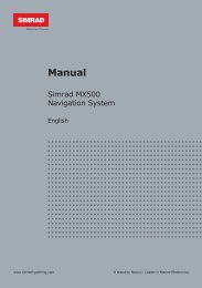
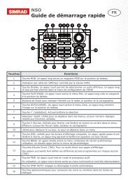
<strong>RS86</strong>/<strong>RS87</strong> <strong>VHF</strong>1.2 The <strong>Simrad</strong> integrated systemThe st<strong>and</strong>ard <strong>RS86</strong>/<strong>RS87</strong> radiotelephone can support up to twostations with full intercom facility, geographical position inputvia SimNet or NMEA 0183, <strong>and</strong> iDSC integration with <strong>Simrad</strong>Chartplotters, which enables the plotters to display DSC callinformation.With the addition of an expansion board, the system can supportan additional two stations, two intercom speakers, <strong>and</strong> forward<strong>and</strong> aft foghorn/loudhailer speakers in addition to the st<strong>and</strong>ardfunctions.Additional stations can either be another <strong>RS87</strong>-type telephoneh<strong>and</strong>set, or an <strong>RS86</strong> fixed-panel display with a passive telephoneh<strong>and</strong>set or fistmike, allowing great flexibility in installations(Fig 1.1).BASIC SYSTEMDUAL STATION SYSTEMEXPANDED SYSTEMFig 1.1 - <strong>RS86</strong>/<strong>RS87</strong> system options10 E04819 Issue 1.0
Instruction <strong>Manual</strong>1.3 LicensingNotePrior to use please check the national licensing requirementsfor operators.In the UK license applications <strong>and</strong> queries should be made tothe following authority:Ship <strong>Radio</strong> Licencing<strong>Radio</strong> Licencing CentreThe Post OfficePO Box 1495Bristol BS99 3QSWebsite: www.radiolicencecentre.co.uk/rlcA set may only be operated by or under the supervision of theholder of a Marine <strong>Radio</strong> Operator’s Certificate of Competence<strong>and</strong> Authority to Operate. This is awarded on completion of theMarine Short Range Certificate course administered by the RoyalYachting Association:Royal Yachting AssociationRYA HouseEnsign WayHambleSouthampton SO31 4YAWebsite: www.rya.org.ukTel. 0845 345 0400Holders of the Restricted Certificate of Competence in <strong>Radio</strong>telephony(which covers MF/HF SSB, etc.) do not need a separate<strong>VHF</strong> certificate.In all other countries, please contact your regional authority forinformation.1.4 <strong>Radio</strong> Frequency exposure guidelinesNoteNorth American Users – To meet FCC (Federal CommunicationsCommission) rules on <strong>Radio</strong> Frequency exposure, it is recommendedthat the <strong>VHF</strong> antenna is mounted at least 3 m (10 ft)away from any area accessible to any personnel on board. If thisdistance is achieved by vertical separation, the antenna must beat least 5 m (16.5 ft) above deck. This guideline applies only toantennas not exceeding 9dBi gain.WarningFailure to observe these recommendations mayexpose those within the MPE (maximum permittedexposure) radius of 3 m (10 ft) to RF absorptionlevels that exceed the FCC safe limits.E04819 Issue 1.011
<strong>RS86</strong>/<strong>RS87</strong> <strong>VHF</strong>1.5 MMSI numberAt the time of issue of your vessel’s radio license an MMSI(Maritime Mobile Service Identity) number must be requested.This is a nine-digit number which must be permanently enteredinto the <strong>RS86</strong>/<strong>RS87</strong> when the radio is first set up, otherwise theDSC functions cannot be accessed.NoteIf the boat or the <strong>RS86</strong>/<strong>RS87</strong> are subsequently sold, the radioshould be returned to an authorized <strong>Simrad</strong> agent for the MMSInumber to be erased <strong>and</strong> the new owner’s MMSI number entered.An MMSI number will only be issued to licensed <strong>and</strong> certifiedusers. Please enquire with your local licensing authority for fulldetails.➞ Refer to section 3.2.1 on how to enter the vessel’s MMSInumber.1.6 ATIS numberSome countries require an ATIS number (e.g. Benelux <strong>and</strong> theRhine/Danube waterways); however, this option will only appearon ATIS-equipped radios.➞ Refer to section 3.2.2 for information on how to enter anATIS number.1.7 Group ID MMSIFor boats that are part of a flotilla, racing fleet, or other group, aGroup ID MMSI number can also be entered, which will allowDSC communication within the group.NoteContact your local authority for rules regarding Group MMSIallocation. In some countries, where ATIS is in use, Group MMSInumbers may not be permitted.➞ Refer to section 3.2.3 on how to enter a Group MMSI number.12 E04819 Issue 1.0
Instruction <strong>Manual</strong>2 MAIN FUNCTIONS2.1 General notesAlthough it has many advanced features, the <strong>RS86</strong>/<strong>RS87</strong> hasbeen designed to be as simple <strong>and</strong> intuitive to operate as possible.The SHIFT key is used to access the secondary functions printedabove each key – press <strong>and</strong> release SHIFT, then press the appropriatekey. These secondary functions are shown in this manualin brackets, e.g. (GROUP).Note The SHIFT key will automatically time out of Shift mode after 2seconds if another key is not pressed.At any time, pressing ON/C will cancel the current operation.The lowest occupied port is the master controller – any operationsinitiated on this h<strong>and</strong>set will therefore override all otherstations.NoteIn order for other users to be able to operate the radio, it isimperative that the h<strong>and</strong>set is replaced in the cradle after use.2.2 Switching on & Second Country modeTo turn the radio on, press the ON/C key. The display will showthe h<strong>and</strong>set software issue number for 2 seconds, then the stationnumber <strong>and</strong> software issue number for the transceiver unitfor 2 seconds.As a default, the radio switches on tuned to the priority channel(normally 16). If Last used channel mode has been set (see section3.3.3), the radio will switch on tuned to the previously usedchannel. The radio also stores the previous volume <strong>and</strong> squelchsettings <strong>and</strong> will use these on start-up.In countries where it is permitted, the <strong>RS86</strong>/<strong>RS87</strong> can operateon a secondary set of channels, such as the USA channels.To select the secondary channel table, press SHIFT followed byOK. The display will show the channel set selected for 2 secondsbefore reverting to the default display.NoteChannels available will depend on programming. Please enquirewith your national licensing authority for details of permittedchannel sets in your own country (cf. sections 2.3.1 <strong>and</strong> 8.4).E04819 Issue 1.013
<strong>RS86</strong>/<strong>RS87</strong> <strong>VHF</strong>2.3 Changing channelsTo select a channel, enter the channel number using the numerickeypad (Fig 2.1).INT16VOLUME 05SQUELCH 03INT72VOLUME 05SQUELCH 03Fig 2.1 - Selecting a channelIf the channel is invalid, the display will show “INVALIDCHANNEL” <strong>and</strong> then revert to the previous channel.The priority channel (normally 16) can be selected by pressing16, which will also set the radio to 25W transmit power.The preselected User channel can be directly selected by pressingthe USER key. The display will show “U” next to the channelnumber to indicate that it is the User channel (Fig 2.2).INTU 23VOLUME 05SQUELCH 03Fig 2.2 - User channel selectedThe default setting for the User channel is 16.➞ Refer to section 3.3.1 for details on setting the User channel.14 E04819 Issue 1.0
Instruction <strong>Manual</strong>2.3.1 Additional channelsIn addition to the st<strong>and</strong>ard international channels, the <strong>RS86</strong>/87can also be programmed with regional auxiliary channels, suchas the Marina channels M <strong>and</strong> M2 in the UK, the USA Weatherchannels, <strong>and</strong> the Fishing or Leisure channels in Sc<strong>and</strong>inavia.To display the channel sets available, press SHIFT followed by1W (CH SET). Multiple pressing of the 1W key, while still inShift mode, will scroll through the available channel sets (Fig 2.3).INTMAR I NAAAAAMAR I NAAAAAPR I VATE AAAFig 2.3 - Selecting auxiliary channel sets(sets must be available to be displayed)When the required channel set is displayed, enter the channelnumber using the numeric keypad, e.g. “2” for M2 (Fig 2.4).NoteINT2MAR I NAAAAAFig 2.4 - Selecting auxiliary channel numberThe only exception to this is when selecting UK Marina channelM, which has no number associated with it. Simply selectingthe Marina channel set will automatically select it.If no numeric keys are pressed within 2 seconds, the radio willrevert to the previous working channel (except for Marinachannel M as noted above).E04819 Issue 1.015
<strong>RS86</strong>/<strong>RS87</strong> <strong>VHF</strong>2.4 Volume adjustmentTo adjust the volume, press the VOL ▲ <strong>and</strong> VOL ▼ keys (rotatethe VOLUME control) to increase or decrease the setting, respectively.Press <strong>and</strong> hold a VOL key to increase/decrease the settingrapidly. The volume setting can be between 1 <strong>and</strong> 24 (loud).2.5 Squelch adjustmentTo adjust the squelch setting, press the SQ key (rotate theSQUELCH control) to enter squelch adjustment mode. Thesquelch setting can be between 0 (open) <strong>and</strong> 10.On the <strong>RS87</strong> only: use the VOL ▲ <strong>and</strong> VOL ▼ keys to increaseor decrease the squelch, respectively. Press <strong>and</strong> hold a VOL keyto increase/decrease the setting rapidly.NoteSquelch mode will automatically time out after 2 seconds, unlessanother key is pressed. Squelch mode can also be canceledby pressing the ON/C key.2.6 Dual WatchDual Watch allows the radio to scan between the selected workingchannel <strong>and</strong> the watch channel (the priority channel, normally16).To enter Dual Watch, select the required working channel, thenpress SHIFT <strong>and</strong> 3 (DW) within 2 seconds.If Dual Watch is selected while the h<strong>and</strong>set/fistmike is off cradle,the display will show “PLACE BACK ON CRADLE”. Ifthe h<strong>and</strong>set/fistmike is replaced within 10 seconds of selectingDual Watch, it will automatically initiate Dual Watch.The display will show “D/W” – the large digits on the displayindicate the working channel, with the watch channel shownbelow in small digits (Fig 2.5).INT6DWD/WAAAAA 16BBBBBBBBBBFig 2.5 - Dual Watch mode16 E04819 Issue 1.0
Instruction <strong>Manual</strong>If the radio detects a signal on the watch channel, it will lockonto this <strong>and</strong> the large digits will change to show the watchchannel.NoteNoteAll other stations will also show the Dual Watch display.Normal <strong>VHF</strong> functions will not be available when in Dual Watchmode. To exit Dual Watch, press 16 or ON/C, or lift the h<strong>and</strong>set/fistmike from the cradle.2.7 Tri-WatchTri-Watch allows the radio to scan between the selected workingchannel, the User channel, <strong>and</strong> the watch channel.NotePress & holdTri-Watch cannot be selected if the User channel is set to Ch16.To enter Tri-Watch, select the required working channel, pressSHIFT, <strong>and</strong> then press <strong>and</strong> hold 3 (DW) for 2 seconds.If Tri-Watch is selected while the h<strong>and</strong>set/fistmike is off the cradle,the display will show “PLACE BACK ON CRADLE”. Ifthe h<strong>and</strong>set/fistmike is replaced within 10 seconds of selectingTri-Watch, it will automatically initiate Tri-Watch.The display will show “T/W” – the large digits on the displayindicate the working channel, with the User channel <strong>and</strong> watchchannel shown below in small digits (Fig 2.6).INT10T/WAAAAA 16USERBBBBB6Fig 2.6 - Tri-Watch modeIf the radio detects a signal on the User or watch channel, itwill lock onto this <strong>and</strong> the large digits will change to show therelevant channel.NoteNoteAll other stations will also show the Tri-Watch display.Normal <strong>VHF</strong> functions will not be available when in Tri-Watchmode. To exit Tri-Watch, press 16 or ON/C, or lift the h<strong>and</strong>set/fistmike from the cradle.E04819 Issue 1.017
<strong>RS86</strong>/<strong>RS87</strong> <strong>VHF</strong>2.8 All Scan modeThe scan function cycles the <strong>RS86</strong>/<strong>RS87</strong> sequentially througheach enabled channel, pausing when a signal is detected.Press SHIFT followed by 1 (SCAN ALL) to enter All Scan mode.If All Scan is selected while the h<strong>and</strong>set/fistmike is off cradle,the display will show “PLACE BACK ON CRADLE”. Thisfunction will be canceled, if the h<strong>and</strong>set/fistmike is not returnedto the cradle within 10 seconds.The display will now show “SCAN ALL”. If the radio detectsa signal, it will lock onto this <strong>and</strong> the large digits will changeto show the relevant channel number (Fig 2.7).INT67SCANALLFig 2.7 - All Scan modeIf the radio locks onto a busy channel, pressing OK will manuallycontinue the scan. All Scan will otherwise automaticallyrestart when the channel becomes clear.NoteNoteAll other stations will also show the All Scan display.While in Scan mode, normal <strong>VHF</strong> functions are not available.To exit All Scan, press 16 or ON/C, or lift the h<strong>and</strong>set from thecradle.2.8.1 Dynamic All Scan inhibitIf the radio is constantly locking onto a busy channel duringscanning, this channel can be excluded from the scan by pressingSHIFT then 1 while locked on that channel.The display will show “CHANNEL INHIBITED” <strong>and</strong> the channelwill no longer be included in the scan cycle.➞ The channel can be reinstated using the menu option describedin section 3.1.2.18 E04819 Issue 1.0
Instruction <strong>Manual</strong>2.9 Memory Scan modeMemory Scan gives the option of scanning a preprogrammedset of channels specified by the user (see sections 3.1.4 <strong>and</strong>3.1.5).Press SHIFT then 2 (SCAN M) to enter Memory Scan mode.If Memory Scan is selected while the h<strong>and</strong>set/fistmike is offcradle, the display will show “PLACE BACK ON CRADLE”.If the h<strong>and</strong>set/fistmike is replaced within 10 seconds of selectingMemory Scan, it will automatically initiate Memory Scan.The display will now show “SCAN M”. If the radio detects asignal, it will lock onto this <strong>and</strong> the large digits will change toshow the relevant channel (Fig 2.8).INT68SCANMFig 2.8 - Memory Scan modeIf the radio locks onto a busy channel, pressing OK will manuallycontinue the scan. Memory Scan will otherwise automaticallyrestart when the channel becomes clear.NoteNoteNoteIf only one channel has been entered into the memory, then initiatingMemory Scan will retune the <strong>RS86</strong>/<strong>RS87</strong> to the storedchannel.All other stations will also show the Memory Scan display.While in Memory Scan mode, normal <strong>VHF</strong> functions are notavailable. To exit Memory Scan, press 16 or ON/C, or lift theh<strong>and</strong>set from the cradle.2.9.1 Dynamic Memory Scan deleteIf the radio is constantly locking onto a busy channel duringscanning, this channel can be removed from the Memory Scanby pressing SHIFT then 2 while locked on that channel.The display will show “CHANNEL DELETED” <strong>and</strong> the channelwill no longer be included in the scan cycle.E04819 Issue 1.019
<strong>RS86</strong>/<strong>RS87</strong> <strong>VHF</strong>2.10 Adjusting backlightingThe display <strong>and</strong> keypad are backlit – to set the backlightinglevel, press SHIFT followed by CALL(DIMMER) to enter backlightingmode.Use the VOL ▲ <strong>and</strong> VOL ▼ keys to adjust the backlighting levelfrom off through to level 5.Press OK or ON/C to exit the backlighting mode at the selectedlevel.NoteBacklighting levels will only affect this particular station.2.11 H<strong>and</strong>set/fistmike off cradleWhen a h<strong>and</strong>set/fistmike is lifted off its cradle, all other stationswill show “OCCUPIED” on the display (Fig 2.9). This meansthat these stations are locked out until the h<strong>and</strong>set/fistmike isreturned to the cradle – unless the station is being called onintercom by another station.INT16STAT I ONAA2OCCUP I EDBBFig 2.9 - Station 2 h<strong>and</strong>set is in useNoteThe h<strong>and</strong>set plugged into the lowest numbered port is the designatedmaster unit. Lifting the master h<strong>and</strong>set will overrideall other stations, even if it is displaying “OCCUPIED”. Allother stations will now display “OCCUPIED” in return <strong>and</strong> belocked out.20 E04819 Issue 1.0
Instruction <strong>Manual</strong>3 MENU MODEMenu mode is used to adjust the various settings of the radio,such as channels inhibited from scan, MMSI number programming,<strong>and</strong> User channel selection.To enter Menu mode, press SHIFT followed by 9 (MENU).Use the the VOL ▲ <strong>and</strong> VOL ▼ keys to scroll through the variousmenu options:• Scanning (section 3.1)Options related to the various scanning functions such aschannel inhibit, Memory Scan select, <strong>and</strong> scan dwell time.• Numbers (section 3.2)Entering of ID numbers such as MMSI, Group MMSI, <strong>and</strong>ATIS number (if applicable in country of use).• <strong>VHF</strong> Items (section 3.3)Miscellaneous options such as selection of User channel,last used channel, Interrupt Intercom, <strong>and</strong> speaker settings.To select an option, press OK. To return to normal radio operation,press ON/C.NoteEntering Menu mode will inhibit the operation of the radio. ExitMenu mode before returning the h<strong>and</strong>set/fistmike to the cradleto permit normal operation.3.1 ScanningOnce the Scanning menu option has been selected (see introductionto section 3), use the VOL ▲ <strong>and</strong> VOL ▼ keys to scrollthrough the menu options:• All Scan inhibit (section 3.1.1)• All Scan reset (section 3.1.2)• All Scan show (section 3.1.3)• Memory Scan select (section 3.1.4)• Memory Scan clear (section 3.1.5)• Memory Scan show (section 3.1.6)• Scan dwell time (section 3.1.7)To select an option, press OK. To return to the main menu, pressON/C.3.1.1 All Scan inhibitIf the radio is constantly locking onto a busy channel when scanning,this channel can be inhibited from the scan cycle.E04819 Issue 1.021
<strong>RS86</strong>/<strong>RS87</strong> <strong>VHF</strong>From the Scanning menu (section 3.1) select “ALL SCAN IN-HIBIT” <strong>and</strong> press OK. Enter the relevant channel number usingthe numeric keypad. The display will show the channel number<strong>and</strong> its status – “ALL SCAN” for enabled, or “ALL SCAN IN-HIBITED” for inhibited channels (Fig 3.1).INT65ALL SCANAAINH IB ITEDBFig 3.1 - Selected channel inhibited from scanPress OK to change the channel’s inhibit status – i.e. if it is enabled,pressing OK will inhibit it, <strong>and</strong> vice versa. If the channelis inhibited, it will no longer be included in the All Scan cycle.Enabling the channel will re-select it.Additional channels can be inhibited/enabled by entering thechannel number <strong>and</strong> repeating the above procedure.To exit, press the VOL ▲ or VOL ▼ key to select another Scanningmenu option, or press ON/C to return to the main menu.3.1.2 All Scan resetThis function will reset all inhibited channels. From the Scanningmenu (section 3.1) select “ALL SCAN RESET” <strong>and</strong> pressOK – the display will show “CHANNELS RESET” (Fig 3.2).CHANNELSSSRESETEDBBBFig 3.2 - All inhibited channels resetUse the VOL ▲ or VOL ▼ key to select another Scanning menuoption, or press ON/C to return to the main menu.3.1.3 All Scan showThis function displays all inhibited channels. From the Scanningmenu (section 3.1) select “ALL SCAN SHOW” <strong>and</strong> pressOK. The display will then change to “SHOWING CHANNELS”<strong>and</strong> display all inhibited channels in sequence.22 E04819 Issue 1.0
Instruction <strong>Manual</strong>Press the VOL ▲ or VOL ▼ key to select another Scanning menuoption, or press ON/C to return to the main menu.3.1.4 Memory Scan selectThis function selects the channels to be used in the Memory Scancycle (see section 2.9).From the Scanning menu (section 3.1) select “MEMORY SCANSELECT” <strong>and</strong> press OK. Enter the relevant channel numberusing the numeric keypad. The display will show the channelnumber <strong>and</strong> its memory status – “MEM SCAN” if it is not currentlyselected for Memory Scan, or “MEM SCAN ENABLED”if it is already selected (Fig 3.3).INT65MEM SCANAAINT65MEM SCANAAENABLEDB BCHANNEL CURRENTLY NOT SELECTEDCHANNEL ALREADY SELECTEDFig 3.3 - Selecting a channel for Memory ScanPress OK to change the channel’s Memory Scan status – i.e. ifit is not selected, pressing OK will add it to the Memory Scancycle, <strong>and</strong> vice versa.Additional channels can be added/removed by entering thechannel number <strong>and</strong> repeating the above procedure.Press the VOL ▲ or VOL ▼ key to select another Scanning menuoption, or press ON/C to return to the main menu.NoteNorth American users – Only one Weather channel can be enteredinto the Memory Scan; if another one is selected, it willoverride the existing channel. The Weather channel is not scannedas part of the Memory Scan sequence, it is used by theWeather Watch function (see section 6.1).3.1.5 Memory Scan clearMemory Scan clear will reset all channels previously selectedfor Memory Scan, so that a new set can be selected.E04819 Issue 1.023
<strong>RS86</strong>/<strong>RS87</strong> <strong>VHF</strong>From the Scanning menu (section 3.1) select “MEMORY SCANCLEAR” <strong>and</strong> press OK – the display will show “CHANNELSCLEARED” (Fig 3.4).CHANNELSSSCLEAREDBBBFig 3.4 - All inhibited channels resetPress the VOL ▲ or VOL ▼ key to select another Scanningmenu option, or ON/C to return to the main menu.3.1.6 Memory Scan showThis function displays all channels selected for Memory Scan.From the Scanning menu (section 3.1) select “MEMORY SCANSHOW” <strong>and</strong> press OK. The display will change to “SHOWINGCHANNELS” <strong>and</strong> display all the channels selected for MemoryScan in sequence.Press the VOL ▲ or VOL ▼ key to select another Scanning menuoption, or press ON/C to return to the main menu.3.1.7 Scan dwell timeThis function is used to select the amount of time the <strong>RS86</strong>/<strong>RS87</strong> remains on a channel after it has locked onto it duringscanning (All Scan or Memory Scan) <strong>and</strong> the signal is lost.From the Scanning menu (section 3.1) select “SCAN DWELLTIME” <strong>and</strong> press OK. The display will show “SCAN DWELLTIME XX”, where “XX” is the current dwell time in seconds(Fig 3.5).SCAN DWELLT I ME 04Fig 3.5 - Scan dwell timeThe default time is 0, meaning that the scan will continue assoon as the signal is lost. There are 11 levels from 0–10 seconds– use the numeric keys to enter the scan dwell time <strong>and</strong>press OK, the display will show “DWELL TIME XXSECONDS”.Press the VOL ▲ or VOL ▼ key to select another Scanning menuoption, or ON/C to return to the main menu.24 E04819 Issue 1.0
Instruction <strong>Manual</strong>3.2 NumbersThe Numbers menu is used for entering ID numbers such asMMSI, Group MMSI, <strong>and</strong> ATIS (if applicable in country of use).Once the Numbers menu option has been selected (see introductionto section 3), use the VOL ▲ <strong>and</strong> VOL ▼ keys to scrollthrough the menu options:• Ship’s MMSI (section 3.2.1)• ATIS number (section 3.2.2)• Group MMSI (section 3.2.3)NoteThe ATIS number option will only be shown if the radio is ATISenabled.This feature is only available for sets used in Benelux<strong>and</strong> the Rhine/Danube waterways.To select an option, press OK.To return to the main menu, press ON/C.3.2.1 Ship’s MMSIThis function will display the boat’s MMSI number if it has alreadybeen entered, or will allow the MMSI to be entered if theradio is being used for the first time (see also section 1.5).From the Numbers menu (section 3.2) select “SHIPS MMSI”<strong>and</strong> press OK – the display will show “SHIPS MMSI” <strong>and</strong> theMMSI number (unless the number has not been entered yet, inwhich case it will show “– – –”; Fig 3.6).INT16SH I PS MMS Ii------------Fig 3.6 - Entering the MMSI numberCautionThe MMSI number can only be entered once <strong>and</strong> cannotbe edited by the user. Should it become necessaryto change the MMSI (for example, if the radio is beingmoved to another boat), the radio must be sent to anauthorized <strong>Simrad</strong> service agent for reprogramming.E04819 Issue 1.025
<strong>RS86</strong>/<strong>RS87</strong> <strong>VHF</strong>To enter the MMSI number press OK again. The display willshow “ENTER MMSI” <strong>and</strong> the first dash in the number willstart flashing to indicate that entry can begin.Enter the nine-digit MMSI number using the numeric keypad<strong>and</strong> press OK. The radio will then ask that the MMSI is reenteredto confirm. If the two numbers do not match, the MMSIwill need to be re-entered <strong>and</strong> re-confirmed.Use the CALL<strong>and</strong> MSGkeys to move the cursor to correctany errors. The cursor position is indicated by the number flashing.Enter a new number to overwrite an incorrect number.NoteThe MMSI number will not be accepted, unless all nine digitshave been entered.Use the VOL ▲ / VOL ▼ keys to select another Numbers menuoption, or press ON/C to return to the main menu.Note3.2.2 ATIS numberThis section applies only to radios used in countries where theATIS system is in operation (i.e. Benelux <strong>and</strong> the Rhine/Danubewaterways). This option will only appear on ATIS-equipped radios(see also section 1.6).From the Numbers menu (section 3.2) select “ATIS NO” – thedisplay will show “ATIS NO” <strong>and</strong> the ATIS number (unless thenumber has not been entered yet, in which case it will show“– – –”).CautionThe ATIS number can only be entered once <strong>and</strong> cannotbe edited by the user. If it is necessary to change theATIS number, the radio must be sent to an authorized<strong>Simrad</strong> service agent for reprogramming.To enter the ATIS number press OK again. The display will show“ENTER ATIS” <strong>and</strong> the first dash in the number will start flashingto indicate that entry can begin.Enter the nine-digit ATIS number using the numeric keypad <strong>and</strong>press OK. The radio will then ask that the number is re-enteredto confirm. If the two numbers do not match, the number willneed to be re-entered <strong>and</strong> re-confirmed.Use the CALL<strong>and</strong> MSGkeys to move the cursor to correctany errors. The cursor position is indicated by the number flashing.Enter a new number to overwrite an incorrect number.26 E04819 Issue 1.0
Instruction <strong>Manual</strong>NoteThe ATIS number will not be accepted, unless all nine digits havebeen entered (the prefix 9 is automatically inserted by the radio).Press the VOL ▲ or VOL ▼ key to select another Numbers menuoption, or ON/C to return to the main menu.3.2.3 Group MMSIFor boats that are part of a flotilla, racing/fishing fleet, or othergroup, a Group ID MMSI number can also be entered <strong>and</strong> usedto contact other boats in the same fleet (see section 1.7).NoteThe Group MMSI number may be allocated on a temporary basisby the local administration, for this reason the number canbe changed by the user.From the Numbers menu (section 3.2) select “GROUP MMSI”– the display will show “GROUP MMSI” <strong>and</strong> the Group MMSInumber (unless the number has not been entered yet, in whichcase it will show “0 – – –”).To enter the Group MMSI number press OK again. The displaywill show “ENTER MMSI” <strong>and</strong> the first dash in the numberwill start flashing to indicate that entry can begin. The first digitof a Group MMSI is always 0, <strong>and</strong> this is preselected by theradio. Enter the remaining eight digits using the numeric keypad,then press OK (Fig 3.7).INT16GROUP MMS II0436 1 ----Fig 3.7 - Entering a Group MMSI numberUse the CALL<strong>and</strong> MSGkeys to move the cursor to correctany errors. The cursor position is indicated by the numberflashing. Enter a new number to overwrite an incorrect number.NoteThe number will not be accepted, unless all eight digits havebeen entered.Press the VOL ▲ or VOL ▼ key to select another Numbers menuoption, or ON/C to return to the main menu.E04819 Issue 1.027
<strong>RS86</strong>/<strong>RS87</strong> <strong>VHF</strong>3.3 <strong>VHF</strong> ItemsThe <strong>VHF</strong> Items menu contains the settings for miscellaneousitems, such as User channel, position view, auxiliary audio, <strong>and</strong>speaker settings amongst others.Once the <strong>VHF</strong> Items menu option has been selected (see introductionto section 3), use the VOL ▲ <strong>and</strong> VOL ▼ keys to scrollthrough the menu options:• User channel (section 3.3.1)• Position view (section 3.3.2)• Last used channel (section 3.3.3)• Interrupt Intercom (section 3.3.4)• Auxiliary audio (section 3.3.5)• Speaker settings (section 3.3.6)• SimNet Management (section 3.3.7)• Lighting modes (section 3.3.8)To select an option, press OK.To return to the main menu, press ON/C.3.3.1 User channelThis is a user-programmable priority channel that is used in theTri-Watch function <strong>and</strong> is selected by pressing the USER key.From the <strong>VHF</strong> Items menu (section 3.2) select “USER CHAN-NEL” <strong>and</strong> press OK.Enter the channel number using the numeric keypad <strong>and</strong> pressOK. The display will show “SET USER CHANNEL” (Fig 3.8).INT10SET USERAACHANNELBBBFig 3.8 - Setting the User channelPress the VOL ▲ or VOL ▼ key to select another <strong>VHF</strong> Itemsmenu option, or ON/C to return to the main menu.28 E04819 Issue 1.0
Instruction <strong>Manual</strong>3.3.2 Position viewThis option allows the user to view the current GPS position thatwill be used if a distress call is made (Fig 3.9). The function ofthis option depends on whether the position is being receivedautomatically via NMEA, or if it has been entered manually.INTLATLON1689º 23. 000N102º 54. 120EFig 3.9 - Position displayFrom the <strong>VHF</strong> Items menu (section 3.2) select “POSITIONVIEW” <strong>and</strong> press OK.If GPS position information is being received, the display willshow “POSITION VIEW OFF”. Press the OK key to togglebetween “ON” <strong>and</strong> “OFF”. When this option is turned on, thebottom two lines of the display will show the current Lat/Longposition on all h<strong>and</strong>sets. If the volume or squelch is adjusted,the display will show the settings while the VOL ▲ / VOL ▼ keys(controls) are operated, before reverting to the position display.If no GPS position information is being received, the displaywill show “VIEW”. Pressing OK will show the manual positionentered or the last known GPS position. If a position has notbeen entered, the Lat/Long display will show “9 9 9” only.Use the VOL ▲ / VOL ▼ keys to toggle between position <strong>and</strong>time (UTC) displays. Press ON/C to exit.3.3.3 Last used channelNormally the <strong>RS86</strong>/<strong>RS87</strong> will power up on the programmedstart-up channel (usually the priority channel). This functionenables the radio to power up on the last channel used – thedefault setting is “OFF”.From the <strong>VHF</strong> Items menu (section 3.2) select “LAST USEDCHAN” <strong>and</strong> press OK; the current status—“ON” or “OFF”—will be shown. Press OK to toggle between settings.Use the VOL ▲ / VOL ▼ keys to select another <strong>VHF</strong> Items menuoption, or press ON/C to return to the main menu.E04819 Issue 1.029
<strong>RS86</strong>/<strong>RS87</strong> <strong>VHF</strong>3.3.4 Interrupt IntercomThis function is used to specify whether intercom or loudhailerfunctions should be interrupted when a <strong>VHF</strong> transmission isreceived – the default setting is “Y” (Yes).From the <strong>VHF</strong> Items menu (section 3.2) select “INTERRUPTINTERCOM” <strong>and</strong> press OK – the display will show “INTER-RUPT INTERCOM” <strong>and</strong> the current status, “Y” or “N”.Use OK to toggle between interrupt settings.Use the VOL ▲ / VOL ▼ keys to select another <strong>VHF</strong> Items menuoption, or press ON/C to return to the main menu.3.3.5 Auxiliary audioThe auxiliary audio input allows an external audio source to beconnected to the radio <strong>and</strong> outputted through the speaker/intercomsystem (e.g. an FM receiver for weather forecasts).From the <strong>VHF</strong> Items menu (section 3.2) select “AUXILIARYAUDIO” <strong>and</strong> press OK to enter the auxiliary audio sub-menu.Use the VOL ▲ / VOL ▼ keys to select the required auxiliaryaudio settings option:• Use Aux AF• Interrupt Aux AFTo turn the auxiliary audio input on, select “USE AUX AF” –the display will show “USE AUX AF” <strong>and</strong> the current status(“NO” or “YES”). Press OK to toggle between the “ON” <strong>and</strong>“OFF” settings. If “USE AUX AF” is switched on, the externalaudio source will be outputted through all speakers in the systemat the set volume level.NoteWhen this option is turned on, the display will show “USINGAUX AUDIO” on the bottom line of the display. If the volume orsquelch is adjusted, the settings will be shown while they arebeing adjusted, then revert to this display.To specify whether the auxiliary audio input should be interruptedwhen a <strong>VHF</strong> transmission is received, select “INTER-RUPT AUX AF” using the VOL ▲ or VOL ▼ key – the defaultsetting is “YES”. Use OK to toggle between interrupt settings.Use the VOL ▲ / VOL ▼ keys to select another auxiliary audiosub-menu option, or press ON/C to return to the <strong>VHF</strong> Itemsmenu. Press ON/C again to return to the main menu.30 E04819 Issue 1.0
Instruction <strong>Manual</strong>3.3.6 Speaker settingsThe speaker settings option is used to set the individual defaultvolume levels for each station, intercom, <strong>and</strong> loudhailer in thesystem.From the <strong>VHF</strong> Items menu (section 3.2) select “SPEAKERSETTINGS” <strong>and</strong> press OK to enter the sub-menu. Press theVOL ▲ or VOL ▼ key to scroll through each speaker, displayingthe default volume level for each one.NoteOnly connected speakers will be shown.The first option in the sub-menu is “RESET TO DEFAULTS”(Fig 3.10) – pressing OK when this option is displayed will resetall speaker levels to their default settings – the display will show“RESETTING LEVELS”.INT16RESET TO000DEFAULTS00Fig 3.10 - Resetting speaker settings to defaultsTo set the required volume levels for each individual position,use the VOL ▲ / VOL ▼ keys to select the required station <strong>and</strong>press OK. The selected speaker will then emit a continuous toneindicating the current volume level. Use VOL ▲ <strong>and</strong> VOL ▼ (rotatethe VOLUME control) to adjust the volume level as required<strong>and</strong> press OK to confirm.Use the VOL ▲ / VOL ▼ keys to select another station <strong>and</strong> repeatthe above procedure, or press ON/C to return to the <strong>VHF</strong>Items menu. Press ON/C again to return to the main menu.E04819 Issue 1.031
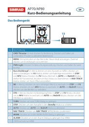
HDG-QPOS-QDIFCOGSOGROT239HS50<strong>RS86</strong>/<strong>RS87</strong> <strong>VHF</strong>Note3.3.7 SimNet ManagementThis option will only appear in the <strong>VHF</strong> Items menu, if the radiois connected to a SimNet bus.From the <strong>VHF</strong> Items menu select “SIMNET MANAGEMENT”<strong>and</strong> press OK.Use the VOL ▲ <strong>and</strong> VOL ▼ keys to scroll through the submenus:• Data sources (section 3.3.7.1)• Lighting banks (section 3.3.7.2)• Device instance (section 3.3.7.3)• <strong>System</strong> instance (section 3.3.7.4)To select an option, press OK. To return to the <strong>VHF</strong> Itemsmenu, press ON/C.3.3.7.1 Data sourcesThis function is used to select the data source for position, date<strong>and</strong> time information, if the <strong>RS86</strong>/<strong>RS87</strong> is part of a SimNetsystem with more than one unit providing nav data (Fig 3.11).It will only be shown if SimNet is present.CP44 ChartplotterHS50Satellite CompassFig 3.11 - Example of multiple data sources on one SimNet systemAs a default, the <strong>RS86</strong>/<strong>RS87</strong> will give priority to SimNet dataover that received via the NMEA input. This function enablesyou to select the NMEA input as the priority data source.From the SimNet Management menu select “DATA SOURCES”<strong>and</strong> press OK. Use the VOL ▲ <strong>and</strong> VOL ▼ keys to scroll throughthe options:<strong>Simrad</strong> group – (Default) Accepts the data source as specifiedby the group owner. A group owner is a unit capableof dictating which data source other SimNetunits on the bus use. The group owner is usually aChartplotter or similar unit.NMEA 0183 – This option will select the NMEA 0183 input asthe nav data source.32 E04819 Issue 1.0
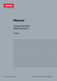
<strong>RS86</strong>/<strong>RS87</strong> <strong>VHF</strong>Use the VOL ▲ <strong>and</strong> VOL ▼ keys to select the station you wantto assign to a particular lighting bank. Use the numeric keypadto enter the bank number (0–63). Press OK to confirm.Repeat the above sequence for each station fitted to the <strong>RS86</strong>/<strong>RS87</strong>.Press ON/C to exit to the SimNet Management menu.NoteAll IS12 instruments are set to “BANK 0” by default. It is notpossible to split IS12 displays into separate banks.3.3.7.3 Device instanceThis option will normally only be used on very large, complicatedsystems, where there is more than one RS80 system onthe same SimNet bus. For example, on certain vessels it may benecessary to have more than one <strong>VHF</strong> radio fitted with differentchannel configurations (Fig 3.13).<strong>VHF</strong> #1<strong>VHF</strong> #2Fig 3.13 - Multiple RS80 <strong>VHF</strong>s on the same networkTo prevent conflict across the network, these can each be assigneda unique device number.Note“More than one RS80 system” refers to a complete system radio,including the Rx/Tx transceiver, NOT to a single <strong>RS86</strong>/<strong>RS87</strong>with multiple stations – that is still classed as one radio.From the SimNet Management menu select “DEVICE IN-STANCE” <strong>and</strong> press OK.The default device instance number is “000”. Use the numerickeypad to enter the required device instance number <strong>and</strong> pressOK to confirm (see Fig 3.14, p. 35).The display will show “SELECTED” <strong>and</strong> the entered devicenumber for 2 seconds, then exit to the SimNet Managementmenu.34 E04819 Issue 1.0
Instruction <strong>Manual</strong>SELECTNO. 000SELECTNO. 001Fig 3.14 - Entering a device number3.3.7.4 <strong>System</strong> instanceA SimNet bus can have a maximum of 50 devices (or “nodes”)attached to it. If a large vessel has a requirement for more than50 nodes, then a multiple network system is required.The system instance allows the user to allocate a unique numberto each network, which allows multiple networks to intercommunicate.NoteIf your vessel is large enough that it is likely to require settingup multiple networks, it is strongly advised that you contact<strong>Simrad</strong> Technical Support to discuss your particular system requirementsbefore proceeding further.From the SimNet Management menu select “SYSTEM IN-STANCE” <strong>and</strong> press OK.The default system instance number is “00”. Use the numerickeypad to enter the required system instance number <strong>and</strong> pressOK to confirm (Fig 3.15).SELECTNO. 00SELECTNO. 01Fig 3.15 - Entering a system instance numberE04819 Issue 1.035
<strong>RS86</strong>/<strong>RS87</strong> <strong>VHF</strong>The display will show “SELECTED” <strong>and</strong> the entered systemnumber for two seconds, then exit to the SimNet Managementmenu.3.3.8 Lighting modesThis option is used to select how the backlighting is controlledon the <strong>RS86</strong>/<strong>RS87</strong>. Backlighting control can either be limitedto the individual station, to the whole RS80 system, or acrossthe SimNet bus (Fig 3.16).From the <strong>VHF</strong> Items menu select “LIGHTING MODES” <strong>and</strong>press OK.Use the VOL ▲ <strong>and</strong> VOL ▼ keys to scroll through the options:Station<strong>Radio</strong>NetworkAll stations are independent.All stations will respond to a common level.All stations respond to the network level (forthe specified lighting bank).STATIONRADIONETWORKFig 3.16 - Lighting modesPress OK to set the selected lighting mode. The display willshow the lighting mode selected, then exit to the <strong>VHF</strong> Itemsmenu.NoteThis option is station specific. It will be necessary to duplicatethese settings to any other RS80 stations for them all to behavein the same manner.36 E04819 Issue 1.0
Instruction <strong>Manual</strong>4 DSC FUNCTIONS4.1 GeneralThe <strong>RS86</strong>/<strong>RS87</strong> features full Class D DSC (Digital SelectiveCalling) functionality, enabling the user to make digitally selectedcalls which are quicker <strong>and</strong> simpler to make than traditionalvoice calls using Ch16. Should a distress situation occur, aDistress Alert call indicating the vessel’s identity <strong>and</strong> positioncan be initiated <strong>and</strong> automatically establish distress communicationon the emergency voice channel (normally Ch16).NoteDSC functions will only be available, if the MMSI number hasbeen entered into the radio (see section 3.2.1).4.2 Making a call4.2.1 Individual routine callPress the CALLkey to enter the Individual routine call function.Either manually enter the MMSI number of the station using thenumeric keypad, or press the VOL ▲ <strong>and</strong> VOL ▼ keys to scrollthrough the MMSI number directory (Fig 4.1). Press OK to confirmthe selected entry.INT06SEA M I STAAON CH 06 00Fig 4.1 - Selecting a number from the MMSI directoryEnter the required working channel using the numeric keypad,or use the VOL ▲ / VOL ▼ keys to scroll through the four defaultreply channels (06, 08, 72 & 77). Press OK to confirm.NoteNoteOnly simplex channels can be selected as the working channel.If the MMSI entered is for a coast station, the option to select aworking channel will not be available – this is specified by thecoast station <strong>and</strong> will normally be a duplex channel.The display will show “PRESS OK TO SEND” – press OK toinitiate the call or ON/C to abort.E04819 Issue 1.037
<strong>RS86</strong>/<strong>RS87</strong> <strong>VHF</strong>On initiation of the call, the display will show “AWAITINGACKNOWLEDG” (Fig 4.2). Once an acknowledgment is received,the radio will automatically switch to the specifiedworking channel.INT06AWA I T I NGAAACKNOWLEDGFig 4.2 - Call sent, awaiting acknowledgment from recipientNoteIf an acknowledgment is not received, the radio will continueshowing the “AWAITING ACKNOWLEDG” display for 4 1 /2minutes before timing out <strong>and</strong> returning to normal operation.4.2.2 Public correspondence callFor vessels within range of a country operating the necessarynetwork, the <strong>RS86</strong>/<strong>RS87</strong> can be used to directly make <strong>and</strong> receivepublic correspondence calls from a l<strong>and</strong>-based telephonesystem via a coast station.Press SHIFT then ON/C to enter the Public correspondence callfunction.Either manually enter the telephone number using the numerickeypad (Fig 4.3), or use the VOL ▲ <strong>and</strong> VOL ▼ keys to scrollthrough the telephone number directory. Press OK to confirmthe selected entry.INT0644 1 606547677------Fig 4.3 - Dialing a number manuallyNoteCheck with your local network provider for usage instructions.38 E04819 Issue 1.0
Instruction <strong>Manual</strong>The next stage is to specify the coast station the call is to berouted through. Either manually enter the MMSI number of thecoast station using the numeric keypad, or press the VOL ▲ <strong>and</strong>VOL ▼ keys to scroll through the Coast Station MMSI numberdirectory (Fig 4.4). Press OK to confirm the selected entry.INT06COAST 1 AAAFig 4.4 - Selecting a coast station from the Coast Station directoryNoteThe MMSI number entered must have two leading zeros (indicatinga coast station) or it will not be accepted.The display will show “PRESS OK TO SEND” – press OK toinitiate the call or ON/C to abort.On initiation of the call, the display will show “ATTEMPTINGTO CONNECT”. If the call cannot be connected for any reason,the display will show “CANNOT CONNECT”, then “PLSWAIT 15 MINUTES” before returning to the default display.If the call is connected, the display will show “CALL IN PRO-GRESS” (Fig 4.5) – press the PTT key to talk <strong>and</strong> release tolisten.INT07CALL I N AAAPROGRESSBBFig 4.5 - Call has been connectedNoteThe channel number displayed during the call is determined bythe coast station.Press ON/C to end the call or wait for the other participant toreplace the receiver.E04819 Issue 1.039
<strong>RS86</strong>/<strong>RS87</strong> <strong>VHF</strong>4.2.3 All Ships Safety callTo make an All Ships Safety call, lift the protective cover on thefront of the h<strong>and</strong>set <strong>and</strong> press the SAFETY key. The display willshow “SAFETY ON CH 16” (Fig 4.6).INT06SAFE T YAAAAON CH 16 00Fig 4.6 - Making an All Ships Safety callEnter the required working channel using the numeric keypad,or use the VOL ▲ / VOL ▼ keys to scroll through the four defaultreply channels (06, 08, 72 & 77). Press OK to confirm.NoteOnly simplex channels can be selected as the working channel.The display will show “PRESS OK TO SEND” – press OK toinitiate the call or ON/C to abort.4.2.4 All Ships Urgency callTo make an All Ships Urgency call, lift the protective cover onthe front of the h<strong>and</strong>set <strong>and</strong> press the URGENCY key. The displaywill show “URGENCY ON CH 16” (Fig 4.7).INT06URGEN CYAAAON CH 16 00Fig 4.7 - Making an All Ships Urgency callNoteAs All Ships Urgency calls must use Ch16 for voice communication,the option to manually select a working channel is notavailable.The display will show “PRESS OK TO SEND” – press OK toinitiate the call or ON/C to abort.40 E04819 Issue 1.0
Instruction <strong>Manual</strong>4.2.5 Group callPress the SHIFT key twice to enter the Group call function – thedisplay will show the Group MMSI number stored in the radio(see section 3.2.3).Enter the required working channel using the numeric keypad,or use the VOL ▲ <strong>and</strong> VOL ▼ keys to scroll through the four defaultreply channels (06, 08, 72 & 77). Press OK to confirm (Fig4.8).INT06026530 1 45ON CH 06BFig 4.8 - Making a group callNoteOnly simplex channels can be selected as the working channel.The display will show “PRESS OK TO SEND” – press OK toinitiate the call or ON/C to abort.Warning4.2.6 Distress Alert callThis call should only be made if the vessel is in agenuine distress situation. It is an offense to senda Distress Alert call, if the vessel or crew are notin grave <strong>and</strong> imminent danger.The DISTRESS button is located under the protective cover onthe front of the h<strong>and</strong>set. Press the DISTRESS button to access theDistress Alert call function – the display will show “DISTRESSUNDEFINED” (Fig 4.9).INT--D I STRESSAAUNDEF I NED bFig 4.9 - Distress Alert menuE04819 Issue 1.041
<strong>RS86</strong>/<strong>RS87</strong> <strong>VHF</strong>Use the VOL ▲ or VOL ▼ keys to scroll through the availableNature of distress categories <strong>and</strong> press OK to confirm selection:• Undefined (default)• Ab<strong>and</strong>oning• Piracy• MOB• Fire• Flooding• Collision• Grounding• Listing• Sinking• AdriftPress <strong>and</strong> hold the DISTRESS key to begin the 5-second countdown– the large digits will count down from 5 to 1 before initiatingthe Distress Alert – the display will show “SENDINGALERT” (Fig 4.10).INT--SEND I NGAAAALER T BBBBBFig 4.10 - Sending a Distress AlertNoteThe Distress Alert call can be aborted if the DISTRESS key is releasedat any time before the 5-second countdown has ended.Press ON/C to return to normal radio operation.The Distress Alert call sent includes the vessel’s MMSI, thenature of the distress as specified, the time the call was sent,<strong>and</strong> the current position of the vessel (if the appropriate navigationalreceiver is connected to the radio, or a manual positionhas been entered; see section 6.4).The radio will switch to monitoring channel 16 <strong>and</strong> the displaywill show “AWAITING ACKNOWLEDG” until an acknowledgmentis received. The radio will automatically repeat thealert approximately every 4 minutes until either an acknowledgmentis received, or ON/C is pressed (it is not recommendedthat the Distress Alert is canceled manually by pressing ON/C,unless you are requested to do so by the rescue authorities).42 E04819 Issue 1.0
Instruction <strong>Manual</strong>When an acknowledgment is received from the rescue coordinationcenter, this will automatically cancel the DistressAlert transmission. The subsequent rescue co-ordination will beperformed using the voice working channel (Ch16).WarningIf a DSC Distress Alert is sent accidentally, cancelit immediately on the <strong>RS86</strong>/<strong>RS87</strong> by pressing theON/C button to prevent repeats, then make thefollowing announcement on channel 16:“This is (name of vessel, callsign, MMSI)”“Cancel DSC Alert sent (date & time UTC) – Over.”Do not simply cancel the DSC alert without verballycanceling it as well, otherwise the rescueauthorities will not be aware that this is a falsealarm.4.3 Receiving a call4.3.1 Individual routine callIf an individual routine call is received, the radio will sound anincoming call alarm. The display will flash between displaying“CALL FROM”, the caller’s MMSI, <strong>and</strong> the specified workingchannel (Fig 4.11). If the caller’s MMSI is stored in the MMSIdirectory (see section 5.2), then the display will show the namestored instead of the MMSI number.INT10CALL FROMA3453428599REPLY ONA0CH 0628599Fig 4.11 - Receiving an individual routine callPress OK to accept the call or ON/C to reject the call. If the callhas been accepted, the display will show “SEND ACKNOWL-EDG”. Press OK to send a call acknowledgment <strong>and</strong> automaticallyswitch to the specified working channel.E04819 Issue 1.043
<strong>RS86</strong>/<strong>RS87</strong> <strong>VHF</strong>4.3.2 Public correspondence callA public correspondence call is a call made from a l<strong>and</strong>-basedtelephone which is routed via a coast station. This is only availablein countries operating the necessary network.NoteAt present, it is not possible to receive incoming calls on thepublic correspondence network – calls can only be made fromthe radio. This section is for reference purposes only.When a public correspondence call is received, the radio willsound an incoming call alarm. The display will flash betweendisplaying “TEL CALL FROM” <strong>and</strong> the caller’s telephonenumber. If the caller’s number is stored in the Telephone numberdirectory (see section 5.2), then the display will show thename stored instead of the telephone number (Fig 4.12).INT10TEL CALLA0FROM428599SIMRAD ONA08599Fig 4.12 - Receiving a public correspondence callPress OK to accept the call – the display will show “CALL INPROGRESS”– or ON/C to reject the call.NoteAs the telephone call is transmitted via a <strong>VHF</strong> channel specifiedby the coast station, it will still be necessary to press thePTT key to talk <strong>and</strong> release it to listen, as with a normal <strong>VHF</strong>call. The coast station will disconnect the call, if the PTT is notpressed for 5 seconds at least every 45 seconds.To end the call, press the ON/C key or wait until the caller replacesthe receiver (an End Call signal will be sent to the radio).Replace the h<strong>and</strong>set/fistmike in the cradle.44 E04819 Issue 1.0
Instruction <strong>Manual</strong>4.3.3 All Ships Safety callIf an All Ships Safety call is received, the radio will sound anincoming call alarm.The display will flash between displaying “ALL SHIPS SAFE-TY” <strong>and</strong> the caller’s MMSI. If the caller’s MMSI is stored inthe MMSI directory (see section 5.2), the display will show thename stored instead of the MMSI number.Press OK to accept the call – the display will change to “REPLYON CH X”, where “X” is the specified working channel, or pressON/C to reject the call.Press OK again to automatically switch to the working channel.4.3.4 All Ships Urgency callIf an All Ships Urgency call is received, the radio will sound anincoming call alarm.The display will flash between displaying “ALL SHIPS UR-GENCY” <strong>and</strong> the caller’s MMSI. If the caller’s MMSI is storedin the MMSI directory (see section 5.2), the display will showthe name stored instead of the MMSI number (Fig 4.13).INT10ALL SHIPSSSURGENCY9 9FROMPRAY 0SEASPRAY 0Fig 4.13 - Incoming All Ships Urgency callPress OK to accept the call <strong>and</strong> automatically switch to channel16, or ON/C to reject the call.NoteAll Ships Urgency calls always use channel 16 as the workingchannel.E04819 Issue 1.045
<strong>RS86</strong>/<strong>RS87</strong> <strong>VHF</strong>4.3.5 Group callIf the radio has a Group MMSI number entered (see section3.2.3) <strong>and</strong> a group call is received, the radio will sound an incomingcall alarm.The display will flash between displaying “ROUTINE GROUPCALL”, the caller’s MMSI, <strong>and</strong> the specified working channel(Fig 4.14). If the caller’s MMSI is stored in the MMSI directory(see section 5.2), the display will show the name stored insteadof the MMSI number.INT06ROUT I NES SGROUP CALLFROMPRAY 03895623970Fig 4.14 - Incoming group callPress OK to accept the call – the display will change to “REPLYON CH X” (Fig 4.15), where “X” is the specified workingchannel, or press ON/C to reject the call.INT06REPLY ONAACH 1 0BBBBBFig 4.15 - Working channel specified by incoming group callPress OK again to automatically switch to the working channel.46 E04819 Issue 1.0
Instruction <strong>Manual</strong>4.3.6 Distress Alert callIf a Distress Alert call is received, the radio will sound an incomingcall alarm.The display will flash between “DISTRESS ALERT” <strong>and</strong> thecaller’s MMSI along with the nature of the distress details.If the caller’s MMSI is stored in the MMSI directory (see section5.2), the display will show the name stored instead of theMMSI number (Fig 4.16).INT06D I STRESS SALERT CALLS I NK I NG 03453428599Fig 4.16 - Incoming Distress Alert callPress OK to accept the call <strong>and</strong> automatically switch to channel16, or ON/C to reject the call.The full details of the Distress Alert may be viewed in the calllog (see section 4.4).NoteDistress Alert calls always use Ch16 as the working channel.E04819 Issue 1.047
<strong>RS86</strong>/<strong>RS87</strong> <strong>VHF</strong>4.3.7 Distress Alert acknowledgmentIf an acknowledgment is received for a Distress Alert sent (normallyfrom a coast station or rescue co-ordination center), theradio will sound an incoming call alarm.The display will flash between “DISTRESS ACKNOWLEDG”<strong>and</strong> the MMSI of the vessel in distress, or your MMSI if theDistress Alert was sent by the <strong>RS86</strong>/<strong>RS87</strong> <strong>and</strong> the Distress Alerttransmission sent has been canceled.If the vessel’s MMSI is stored in the MMSI directory (see section5.2), the display will show the name stored instead of theMMSI number (Fig 4.17).INT06D I STRESS SACKNOWLEDGFORK I NG 0ROBERTA0 0Fig 4.17 - Distress acknowledgment receivedNoteThe MMSI/name displayed will be that of the vessel in distress,not the station that has acknowledged the call.Press OK to accept the acknowledgment <strong>and</strong> automaticallyswitch to channel 16, or ON/C to ignore the call.NoteDistress Alert calls always use Ch16 as the working channel.48 E04819 Issue 1.0
Instruction <strong>Manual</strong>4.3.8 Distress relay callThe distress relay facility enables an incoming Distress Alertcall to be passed onwards via boats within receiving distance ofthe call, thus increasing the potential range of the Distress Alertcall.When a distress relay call is received, the radio will sound anincoming call alarm.The display will flash between “DISTRESS RELAY” <strong>and</strong> thevessel’s MMSI (Fig 4.18). If the vessel’s MMSI is stored in theMMSI directory (see section 5.2), the display will show thename stored instead of the MMSI number.INT06D I STRESS SRELAY ALLFOR I NG 03453428599Fig 4.18 - Incoming distress relayNoteThe MMSI/name displayed will be that of the vessel in distress,not the vessel that relayed the call.Press OK to accept the call <strong>and</strong> automatically switch to channel16, or ON/C to reject the call.E04819 Issue 1.049
<strong>RS86</strong>/<strong>RS87</strong> <strong>VHF</strong>4.4 Viewing the call logThe call log records details of the last 20 DSC or telephone callsreceived, including the date <strong>and</strong> time, the type of call, <strong>and</strong> thecaller ID. There are two separate logs: one for st<strong>and</strong>ard calls,the other for distress calls.NoteAll calls are logged, even those rejected by pressing ON/C.Press MSGto enter the Call Log menu. If the call logs areempty, the display will show “NO CALLS RECEIVED” beforereturning to the default display.Press the CALL<strong>and</strong> MSG keys to switch between the st<strong>and</strong>ardcall log (indicated by “1” shown next to the large digits)<strong>and</strong> the distress call log (indicated by “2” shown next to thelarge digits).Press VOL ▲ or VOL ▼ to scroll through the log entries – thedisplay will show the call type <strong>and</strong> the date/time the call was received(Fig 4.19). The small digit shows the log type (“1”- st<strong>and</strong>ardcall log; “2”- distress call log) <strong>and</strong> the large digits show theentry number; the first entry shown is the most recent call.INTMSG1 03I ND I V I DUAL1 9- 1 2 1 452Fig 4.19 - Viewing a call log entryNoteThe date <strong>and</strong> time displayed use the date/time data receivedfrom the navigational receiver interfaced to the radio, not fromthe incoming message. If a navigational receiver was not connectedto the radio at the time the message was received, thedate <strong>and</strong> time will not be displayed.Press OK to view the details of the selected call – the displaywill show the caller’s number (or the name, if the number isstored in the directory).50 E04819 Issue 1.0
Instruction <strong>Manual</strong>Press VOL ▲ or VOL ▼ to display any relevant additional information– for example, the nature of distress <strong>and</strong> position of thevessel in distress if viewing the distress call log (Fig 4.20).INTMSG207D I ST ALERT1 4- 1 0 0937S I NK I NG 03453428599LA 56-52NLO 009-50EFig 4.20 - Displaying additional call informationPress ON/C to return to the log entries menu. Press ON/C againto exit the Call Log menu.4.5 Position over 4 hours oldNormally current position data is supplied automatically to theradio via an interfaced navigational receiver (see section 7.2.7)or by manually entering a position (refer to section 6.4). If thelast recorded position is over 4 hours old, the display will show“POSITION 4 HOURS OLD”.Press OK to confirm <strong>and</strong> manually enter a position, or pressON/C to ignore the message.NoteThis display will be shown 30 minutes after switch on, if thereis no NMEA position data being received or the position hasnot been manually entered.E04819 Issue 1.051
<strong>RS86</strong>/<strong>RS87</strong> <strong>VHF</strong>5 THE DIRECTORYThe Directory function allows frequently used Boat MMSI, CoastStation MMSI, <strong>and</strong> telephone numbers to be stored in the radio.To enter the directory, press SHIFT then MSG(DIR).5.1 Switching between directoriesThe large digits will show the currently displayed entry number<strong>and</strong> the smaller digit to the left of the large digits will show thecurrently selected directory:1. Boat MMSI directory2. Telephone number directory (used in public correspondenceonly)3. Coast Station MMSI directory (used in public correspondenceonly)Use CALL<strong>and</strong> MSG to switch between the directories.5.2 Viewing a directoryUsing the CALL<strong>and</strong> MSG keys select the appropriate directory.Use the VOL ▲ <strong>and</strong> VOL ▼ keys to scroll through thedirectory entries (Fig 5.1).INTDIR10 1SEASPRAY 0475394270INTDIR102ROBERTAY 09463872 1 5Fig 5.1 - Scrolling through the directory entries52 E04819 Issue 1.0
Instruction <strong>Manual</strong>5.3 Entering a numberPress OK to begin entering a new number – the large digits willshow the entry number in the directory (1 if it is the first entry).Enter the name first – use the VOL ▲ or VOL ▼ keys to scrollthrough the alphabetical characters <strong>and</strong> use the numeric keypadto enter any numbers (Fig 5.2).Press MSGto move the cursor forward, or CALL to moveback <strong>and</strong> correct any errors. The cursor position is indicated bythe character flashing; to overwrite enter a new character. PressOK to confirm the entry <strong>and</strong> move on to the MMSI entry.INTDIR1 0 1SEASP---------------Fig 5.2 - Entering a new name into the directoryUse the numeric keypad to enter the number (Fig 5.3). Press theCALL<strong>and</strong> MSGkeys to move the cursor to correct any errors.The cursor position is indicated by the number flashing – enter anew number to overwrite an incorrect number.INTDIR1 0 1SEASPRAY 047539-----Fig 5.3 - Entering the numberPress OK to confirm <strong>and</strong> store the entry to the directory.Press ON/C at any time to abort to the default display.NoteIf using the Boat or Coast Station MMSI directories, the entrywill not be accepted, unless all nine digits of the MMSI numberhave been entered.E04819 Issue 1.053
<strong>RS86</strong>/<strong>RS87</strong> <strong>VHF</strong>5.4 Editing a numberSelect the directory entry to be edited <strong>and</strong> press OK. Use theVOL ▲ <strong>and</strong> VOL ▼ keys to highlight either the name or the numberfor editing – the selected field will flash. Press OK again tobegin editing the selected field.Use the CALL<strong>and</strong> MSGkeys to move the cursor – the cursorposition is indicated by the character flashing. Enter a new characterto overwrite, use the numeric keypad to enter a number, oruse the VOL ▲ / VOL ▼ keys to scroll through the alphabeticalcharacters (Fig 5.4).INTDIR10 1SEASPRAY 0475394270Selectedfield willflashINTDIR10 1SEASP-----475394270Fig 5.4 - Editing an existing directory entryPress OK to confirm <strong>and</strong> store the edited entry or ON/C to abortentry.54 E04819 Issue 1.0
Instruction <strong>Manual</strong>6 MISCELLANEOUS FUNCTIONS6.1 Selecting Weather WatchThe Weather Watch function enables the radio to monitor a singleWeather channel specified in the Memory Scan select function(see section 3.1.4). A transmission on a Weather channel is precededby a tone – if this is detected by the radio, it will sound analert allowing the user to switch to the Weather channel.To enable Weather Watch, press SHIFT followed by the USER(WX WATCH) key. The “WX” legend will appear in the top lefth<strong>and</strong>corner of the display <strong>and</strong> the selected Weather channel willbe shown on the bottom line of the display (Fig 6.1).WX12WEATHERAAAWATCHBBBW4NoteNoteFig 6.1 - Selecting Weather Watch modeIf no Weather channel has been specified, the display will show“NO WX CHAN SELECTED” <strong>and</strong> Weather Watch will not beenabled. (Refer to section 3.1.4 to select a Weather channel.)If the Weather Watch function is not available (for example, ifno Weather channels are programmed into the radio), the displaywill show “WX NOT ENABLED”.To cancel Weather Watch, press SHIFT followed by the USER(WX WATCH) key.6.1.1 Weather Watch AlertIf a Weather Alert tone is detected by the radio on the specifiedWeather channel while Weather Watch is enabled, the radio willsound a 10-second alarm <strong>and</strong> the display will show “WEATHERALERT”. Press OK to cancel the alarm <strong>and</strong> switch to theWeather channel, or ON/C to cancel the alarm <strong>and</strong> ignore theWeather Alert.NoteBecause Weather channels transmit a continuous carrier signal,it is not possible for the <strong>RS86</strong>/<strong>RS87</strong> to detect when the transmissionhas ended.Press ON/C to return to the working channel once the transmissionhas ended.E04819 Issue 1.055
<strong>RS86</strong>/<strong>RS87</strong> <strong>VHF</strong>6.2 Security mode (voice scrambler)For additional security, a voice scrambler function is availableas an optional accessory. The scrambler uses frequency inversionto encrypt the transmission <strong>and</strong> will allow secure transmissionbetween compatible radios.To enable Security mode press SHIFT followed by 0 (SCRM). Thedisplay will show “SEC” indicating that Security mode is on.To exit Security mode, press SHIFT followed by 0 (SCRM) again,or press ON/C. Security mode will be canceled, if the <strong>RS86</strong>/87is placed into another mode that requires the use of the PTTkey (e.g. Hailer/Intercom), or if a DSC call is made/received.6.3 Losing nav data6.3.1 Losing SimNet dataIf the selected SimNet nav data source is lost for any reason,after 1 minute an alarm will sound to all station speakers <strong>and</strong> thedisplay will show “SOURCE DATA LOST” (Fig 6.2).INT16SOURCEDATA LOSTFig 6.2 - SimNet nav data source lostThe alarm will also be sent across the SimNet bus, where it maybe repeated by other equipment that is able to do so.Press OK or ON/C to cancel the alarm <strong>and</strong> return to the previousdisplay. The alarm can also be canceled by other equipment onthe bus that is repeating the alarm.NoteIf nav data is also being received via the NMEA 0183 input, the<strong>RS86</strong>/<strong>RS87</strong> will automatically switch to this source after theloss of SimNet data.6.3.2 Losing NMEA dataIf the NMEA 0183 nav data source is lost (<strong>and</strong> no SimNet navdata is being received), an alarm will sound to all station speakersafter one minute <strong>and</strong> the display will show “NMEA LOST”(see Fig 6.3, p. 57).56 E04819 Issue 1.0
Instruction <strong>Manual</strong>INT16NMEA LOSTFig 6.3 - NMEA 0183 nav data source lostNoteThe alarm for the loss of NMEA 0183 data is not sent acrossthe SimNet bus.Press OK or ON/C to cancel the alarm <strong>and</strong> return to the previousdisplay.6.4 Editing Latitude, Longitude <strong>and</strong> UTCNormally, position <strong>and</strong> time data should be supplied to the<strong>RS86</strong>/<strong>RS87</strong> via a GPS or other navigational device connectedto the radio. However, if this is not possible, the position <strong>and</strong>time can be entered manually:Press SHIFT then 8 (LAT/LON). The display will show “ENTERLAT”. Enter the Latitude using the numeric keypad (Fig 6.4).Use the CALL<strong>and</strong> MSG keys to move the cursor to correctany errors. The cursor position is indicated by the number flashing.Enter a new number to overwrite an incorrect number.INT12ENTER LA T ALA 52-B---Fig 6.4 - <strong>Manual</strong>ly entering positionThe final digit specifies, whether the Latitude is north or southof the Equator – use VOL ▲ / VOL ▼ to toggle between N <strong>and</strong> S.Press OK to confirm <strong>and</strong> move on to entering the Longitude, thedisplay will show “ENTER LON”. Enter the Longitude usingthe numeric keypad. Use the CALL <strong>and</strong> MSG keys to movethe cursor to correct any errors. The cursor position is indicatedE04819 Issue 1.057
<strong>RS86</strong>/<strong>RS87</strong> <strong>VHF</strong>by the number flashing. Enter a new number to overwrite an incorrectnumber. The final digit specifies whether the Longitudeis west or east of the Meridian – use VOL ▲ / VOL ▼ to togglebetween W <strong>and</strong> E.Press OK to confirm <strong>and</strong> move on to entering the time. The displaywill show “ENTER UTC”. Enter the UTC time (formerlyknown as GMT) in 24-hr format using the numeric keypad (Fig6.5). Use the CALL<strong>and</strong> MSGkeys to move the cursor to correctany errors. The cursor position is indicated by the numberflashing. Enter a new number to overwrite an incorrect number.INT12ENTER U T CAUTC 19B----Fig 6.5 - Entering time (UTC) manuallyPress OK to confirm all settings, or ON/C to abort entry at anypoint.WarningThis data is only stored temporarily <strong>and</strong> will belost when the radio is switched off. Since theaccuracy of this information is vital in the eventof a Distress Alert transmission being necessary,we strongly recommend that a GPS or other navigationaldevice is permanently interfaced withthe radio. The data will then be automaticallysupplied <strong>and</strong> updated without the need for userintervention.6.5 Toggling between Lat/Lon <strong>and</strong> UTC viewsIf the Position view option (see section 3.3.2) is turned on, thecurrent position will be displayed on the bottom two lines ofthe display. The UTC time can be displayed instead by pressingSHIFT then holding the 8 (LAT/LON) key down for 2 seconds(Fig 6.6).UTC 19B26-Fig 6.6 - Displaying UTC time58 E04819 Issue 1.0
Instruction <strong>Manual</strong>Repeat the above key sequence to toggle between the position<strong>and</strong> time displays.6.6 IntercomIf the system comprises more than one station <strong>and</strong>/or includesintercom speakers, it is possible to make an intercom call to aselected position from a station.NoteThis assumes that the installation consists of a fully exp<strong>and</strong>ed<strong>RS86</strong>/<strong>RS87</strong> system with up to four stations <strong>and</strong> two intercomspeakers. The options shown will only be available, if the relevantstations/intercoms are installed.6.6.1 Making an intercom callPress SHIFT then 6 (INTERCOM) to enter Intercom mode. Thedisplay will show “INTERCOM STN X–STN Y”, where “X” isthe ID of the current station being used <strong>and</strong> “Y” the first of theother stations in the system (Fig 6.7).INT12I N T ERCOMAASTN 1 -STN2 BFig 6.7 - Making an intercom call to Station 2 from Station 1Use the VOL ▲ <strong>and</strong> VOL ▼ keys to scroll through the availablestations/intercoms that can be called from the station:“Stn 1–Stn 2” Intercom call to Station 2“Stn 1–Stn 3” Intercom call to Station 3“Stn 1–Stn 4” Intercom call to Station 4“Int Spkr 1” Intercom call to Intercom speaker 1“Int Spkr 2” Intercom call to Intercom speaker 2“All Spkrs” Intercom call to all Station speakers“PA”Intercom call to all speakers in system(including horns)Press the PTT key or OK to activate the intercom, or pressON/C to cancel. Once the call has been initiated, further pressesof the OK key will re-sound the call alarm. Pressing the PTTkey will open the audio path to the called station.E04819 Issue 1.059
<strong>RS86</strong>/<strong>RS87</strong> <strong>VHF</strong>NoteThe call will be terminated, if it is not accepted within 15 secs.When calling an intercom speaker, use the VOL ▲ / VOL ▼ keys(rotate the VOLUME control) while the PTT key is held to adjustthe intercom speaker volume. This option is not available whencalling another station or making an All Speaker/PA call – thecurrent volume settings for each position will be used.To end the intercom call, press ON/C or return the h<strong>and</strong>set/fistmiketo its cradle.NoteNoteWhile making an intercom call, all other stations will display“STATION X OCCUPIED”.If the Interrupt Intercom option (section 3.3.4) is disabled <strong>and</strong> a<strong>VHF</strong> transmission is being received, the display will show“SIGNAL PRESENT” until the transmission has ended. If InterruptIntercom is enabled, the intercom call will be interruptedwhen a <strong>VHF</strong> transmission is received.6.6.2 Receiving an intercom callIf an intercom call is received from another station, the displaywill show “INTERCOM FROM STN Y”, where “Y” is the IDof the station making the intercom call (Fig 6.8).INT12I N T ERCOMAAFROM STN 22Fig 6.8 - Receiving an intercom call from Station 2If the other station is making an All Speakers call, the displaywill show “INT ALL FROM STN Y”. If the other station ismaking a PA call, the display will show “PA FROM STN Y”.To accept the call, lift the h<strong>and</strong>set/fistmike from the cradle, orpress ON/C to cancel the intercom call.To end the intercom call, press ON/C or return the h<strong>and</strong>set/fistmiketo its cradle.NoteAll Speaker <strong>and</strong> PA calls are announcement calls <strong>and</strong> thereforedo not need to be accepted manually by the receiving stations.60 E04819 Issue 1.0
Instruction <strong>Manual</strong>6.7 Loudhailers/FoghornUp to two loudhailers/foghorns can be fitted to the <strong>RS86</strong>/<strong>RS87</strong>– one fore <strong>and</strong> one aft.To enter Hailer/Foghorn mode press SHIFT then 5 (HAIL/FOG).The display will show “LOUDHAILER FWD” (Fig 6.9).INT12LOUDHA I LERFWDM STN 22Fig 6.9 - Selecting Loudhailer modeTo toggle between Loudhailer <strong>and</strong> Foghorn mode, press the 5key – the display will now show “FOGHORN FWD”.NoteIf no hailers are connected to the radio, the display will show“HORNS NOT ENABLED”.6.7.1 LoudhailerTo cycle through the loudhailer options, press the 4 key:• Loudhailer Fwd• Loudhailer Aft• Loudhailer BothNoteIf a single loudhailer is fitted, only the “LOUDHAILER FWD”,or “LOUDHAILER AFT” option will show, depending on whereit has been fitted.Press the PTT key to make the loudhailer call. Use the VOL ▲<strong>and</strong> VOL ▼ keys (rotate the VOLUME control) while the PTT ispressed to adjust the hailer volume. Press OK to open the talkbackpath, enabling users at the loudhailer to talk back.Press the ON/C key to exit Loudhailer/Foghorn mode.NoteIf Interrupt Intercom is disabled (see section 3.3.4), the displaywill show “SIGNAL PRESENT” when a <strong>VHF</strong> transmission isbeing received.E04819 Issue 1.061
<strong>RS86</strong>/<strong>RS87</strong> <strong>VHF</strong>6.7.2 FoghornTo select Foghorn, press 5 (HAIL/FOG) while in Loudhailer/Foghornmode – the display shows “FOGHORN FWD” (Fig 6.10).INT12FOGHORN AAFWDM STN 22To cycle through the foghorn options, press the 4 key:• Foghorn Fwd• Foghorn Aft• Foghorn BothFig 6.10 - Selecting Foghorn modeNoteIf a single loudhailer is fitted, only the “FOGHORN FWD”or“FOGHORN AFT”option will show, depending on where it hasbeen fitted.Press OK to enter the Foghorn sub-menu. Use the VOL ▲ <strong>and</strong>VOL ▼ keys to scroll through the available horn tone options:• Horn• Siren• Power Vessel Under Way• Power Vessel Stopped• Restricted Manoeuvre• Working At Anchor• Vessel Being Towed• Vessel In Pilotage• Anchor• AgroundPress PTT or OK to sound the horn. If an external horn buttonis fitted to the radio, pressing this will also sound the horn.NoteFor single activation options (e.g. Horn) it is necessary to pressthe activation button each time to sound the horn. For automaticrepeat options (e.g. Anchor) it is only necessary to press thekey once <strong>and</strong> the foghorn will sound automatically. Press ON/Cto cancel the automatic repeat sequence.62 E04819 Issue 1.0
Instruction <strong>Manual</strong>Adjusting horn volume – for single activation options use theVOL ▲ / VOL ▼ keys (rotate the VOLUME control) while the PTTis pressed. For automatic repeat options, press VOL ▲ / VOL ▼(rotate the VOLUME control) while the display shows “HORN INUSE”. Press the ON/C key to exit the Loudhailer/Foghorn mode.NoteTen seconds after the automatic horn is sounded the unit willrevert to normal radio operation, but the horn will continue tosound.To cancel this mode at any time, press SHIFT followed by 5(HAIL/FOG) again, then ON/C.6.8 Station speaker muteFor complete silence at an operating position, the station speaker(including the h<strong>and</strong>set speaker) can be muted.To mute the speaker, press SHIFT followed by 7 (SPEAKER) onthe specific h<strong>and</strong>set that is used with the speaker.To disable mute, press SHIFT followed by 7 (SPEAKER) again,the VOL ▲ <strong>and</strong> VOL ▼ keys (rotate the VOLUME control), or liftthe h<strong>and</strong>set/fistmike from the cradle. If the system is powereddown, the speaker will be un-muted when the system is turnedon again.Note6.9 iDSCThis will only affect the speaker that is used with this specifich<strong>and</strong>set – e.g. h<strong>and</strong>set 1 will only mute the speaker connected tothe Station 1 terminals. To mute any other speakers on the system,it will be necessary to go to the relevant station <strong>and</strong> selectmute.The <strong>RS86</strong>/<strong>RS87</strong> can be integrated with <strong>Simrad</strong> navigation displays(e.g. 3x, 4x, <strong>and</strong> 5x series Chartplotters) enabling detailsof any incoming DSC calls to be displayed on the unit.➞ Refer to the instruction manual of the relevant unit for moredetails.➞ Refer to section 7.2.8 for interfacing details.E04819 Issue 1.063
<strong>RS86</strong>/<strong>RS87</strong> <strong>VHF</strong>7 INSTALLATION7.1 Physical installationThe <strong>RS86</strong>/<strong>RS87</strong> is a modular system that is very simple to install;however, the performance of the radio is directly affectedby the quality of the installation. Please read these instructionsthoroughly before attempting installation. If in any doubt, consulta qualified marine electronics engineer.Warning7.1.1 Transceiver installationThe transceiver unit is designed to be installed in a concealedlocation such as in a locker or behind the switch panel.The transceiver unit is not waterproof <strong>and</strong> must,therefore, not be installed in any location whereit is likely to be exposed to excess moisture (e.g.a wet locker or an outside locker).The fins on the top of the transceiver act as a heatsink to dissipateheat generated by the set when in use, which maintains thehigh efficiency of the radio. The free circulation of air is essential– if mounting the transceiver in an enclosed space, ensurethat the space is well ventilated.The transceiver requires a flat surface with an area of at least170 x 245 mm (6.8 x 9.8 in) for mounting. Allow sufficientspace beneath the unit to allow cable entry – at least 50 mm(2.0 in) is recommended. The surface should be rigid <strong>and</strong> sturdyenough to be able to support the weight of the unit, taking intoaccount the shock loads likely to be encountered when the vesselis underway in heavy seas.Fix the transceiver unit to the surface using the four selftappingscrews supplied. The four fixing points are at the cornersof the transceiver unit – the bottom two are underneath theterminal cover (Fig 7.1).Fig 7.1 - Transceiver box mounting64 E04819 Issue 1.0
Instruction <strong>Manual</strong>7.1.2 Control panel installation (<strong>RS86</strong>)The control panel should be sited so that engine noise <strong>and</strong>vibrations, or other background noise, do not make it difficultfor the operator to hear.NoteAs microphones <strong>and</strong> loudspeakers contain powerful magnets,the control panel, h<strong>and</strong>set, or fistmike should not be installedwithin 1m (3ft 3in) of any magnetic or electronic compasses.The control panel is connected to the transceiver unit with a5 m (16.5 ft) cable, therefore the control panel should be fittedwithin reach of the transceiver (for longer runs 20 m extensioncables are available as separate accessories; see section 8.6).OverheadmountingDesktopmountingCornermouldingCornermoulding50mm (2.0in)28mm(1.12in)Fig 7.3 - Flush mountingFig 7.2 - St<strong>and</strong> mounting control panelThe control panel can be fitted using the adjustable st<strong>and</strong> suppliedor flush mounted onto a bulkhead. The st<strong>and</strong> (see Fig 7.2above) allows the panel to be fitted to a flat surface using thefour self-tapping screws supplied <strong>and</strong> can be inverted formounting on an overhead surface.If flush mounting the panel, it is necessary to cut two holes inthe bulkhead – a 50 mm (2 in) hole for the speaker recess <strong>and</strong> a28 mm (1.12 in) hole for the rear socket (Fig 7.3). A selfadhesivedrilling template is provided to ensure the holes areaccurately cut. Allow at least 50 mm (2 in) clearance behind thepanel for the interconnecting socket <strong>and</strong> cable. Remove the cornermouldings concealing the mounting holes <strong>and</strong> attach thepanel to the bulkhead using the four self-tapping screws provided.If fitting to a GRP surface, drill 2.5 mm (0.1 in) pilot holesfor the screws <strong>and</strong> countersink them to avoid splitting the gelcoat.The control panel h<strong>and</strong>set/fistmike socket is waterproof, but ifthe control panel is to be fitted in an exposed location (e.g. onE04819 Issue 1.065
<strong>RS86</strong>/<strong>RS87</strong> <strong>VHF</strong>the flybridge of a powerboat), it is recommended that the panelis fitted to an angled or vertical surface to prevent st<strong>and</strong>ingwater inside the bulkhead socket, which could corrode the pins.Note7.1.3 H<strong>and</strong>set installation (<strong>RS87</strong>)The h<strong>and</strong>set should be sited so that engine noise <strong>and</strong> vibration,or other background noise, do not make it difficult for the operatorto hear.As microphones <strong>and</strong> loudspeakers contain powerful magnets,the h<strong>and</strong>set <strong>and</strong> speakers should not be installed within 1 m(3 ft 3 in) of any compasses, whether magnetic or electronic.The h<strong>and</strong>set is connected to a 5 m (16.5 ft) extension cable <strong>and</strong>should therefore be fitted within reach of the transceiver box(for longer runs 20 m extension cables are also available as separateaccessories; see section 8.6).The h<strong>and</strong>set cradle should be mounted on a flat surface withenough space to allow the bulkhead socket for the extensioncable to be fitted alongside. Space should also be allowed nearbyfor the accompanying loudspeaker to be fitted.NoteThe h<strong>and</strong>set <strong>and</strong> bulkhead socket are waterproof, but if theh<strong>and</strong>set is to be fitted in an exposed location (e.g. on the flybridgeof a powerboat), it is recommended that the h<strong>and</strong>set, <strong>and</strong>especially the bulkhead socket, is fitted to an angled or verticalsurface to prevent st<strong>and</strong>ing water lying on the h<strong>and</strong>set face orinside the bulkhead socket, which could corrode the pins.Fit the supplied template for the h<strong>and</strong>set cradle to the desiredmounting location. Drill four 3.2 mm (0.125 in) pilot holes inthe indicated positions. If drilling into GRP, it is recommendedthat the holes are also countersunk to prevent the gelcoat splittingwhen the self-tapping screws are inserted.Fit the supplied template to the desired mounting location forthe bulkhead socket. Drill a 23.5 mm (0.94 in) hole <strong>and</strong> four2.4 mm (0.1 in) pilot holes. Again, the pilot holes should becountersunk if drilling into GRP.Fit the bulkhead socket <strong>and</strong> run the cable to the transceiver boxposition.NoteIt is recommended that the cable is routed away from any othercables carrying high current (e.g. mains power cables) or pulsedsignals (e.g. transducer cables) to avoid possible interference.66 E04819 Issue 1.0
Instruction <strong>Manual</strong>If the h<strong>and</strong>set is being removed, the waterproof cover shouldalways be fitted to the bulkhead socket to protect the pins frompossible corrosion.7.1.4 Station speaker installationThe loudspeaker should be installed near to the h<strong>and</strong>set <strong>and</strong> canbe flush mounted or surface mounted with the supplied pattress.Flush mountingSurface mountingAttach the self-adhesive gasket to the back of the loudspeaker.Remove the four detachable corners of the speaker which concealthe mounting holes. Apply the supplied cutting template tothe mounting position. Carefully cut out the aperture requiredfor the speaker back <strong>and</strong> use the short self-tapping screws provided.Refit the corners to conceal the screw fixings.Drill a 5 mm (0.2 in) hole for the speaker cable. Attach the selfadhesivegasket to the back of the loudspeaker. Remove thefour detachable corners which conceal the mounting holes. Fitthe pattress to the back of the speaker <strong>and</strong> use the long selftappingscrews provided to fix the speaker <strong>and</strong> the pattress blockto the bulkhead. Refit the corners to conceal the screw fixings.7.2 Electronic installationElectronic installation is straightforward – all peripherals connectto the transceiver unit via the clearly labeled plug-in terminals(Fig 7.4; note, the expansion board shown is optional).STANDARD CONNECTIONSFig 7.4 - Transceiver terminal connectionsIf it is necessary to shorten any of the cables, ensure the endsare re-tinned for the best quality connection.The transceiver unit is fitted with a 10 Amp “blade”-type fuse.It is recommended that the radio is connected to a 10 Amp fusedswitch or breaker on the boat’s switch panel.Connect the supplied power cable to the terminals markedPWR + <strong>and</strong> - as follows:TerminalNumber12EXPANSION BOARDWireColorRedBlackE04819 Issue 1.067
<strong>RS86</strong>/<strong>RS87</strong> <strong>VHF</strong>7.2.1 Control stationsA single cable links the control panel to the transceiver unit. Thest<strong>and</strong>ard model can support up to two control stations, or up tofour stations if an expansion board is fitted. One fixed station issupplied with the radio, additional stations are supplied as separateaccessories. The control stations can be either a h<strong>and</strong>setmodel (<strong>RS87</strong>), which is supplied with a separate loudspeaker,or a fixed control panel (<strong>RS86</strong>) with a passive fistmike/h<strong>and</strong>set.Connect the main control station to the “STATION 1” terminalson the transceiver unit as shown (Fig 7.5).TerminalNumber12345678WireColorBrownGreenRedWhiteBlueYellowOrangeBlackFig 7.5 - Control station terminal connectionsAdditional control stations should be wired in the same manner<strong>and</strong> connected to the “STATION 2”, “STATION 3”* <strong>and</strong>“STATION 4”* terminals (Fig 7.6).*Only available on models fitted with an expansion boardStation 1Station 3*Station 2Station 4*Fig 7.6 - Example of a typical multi-station installation68 E04819 Issue 1.0
Instruction <strong>Manual</strong>7.2.2 LoudspeakersThe <strong>RS86</strong>/<strong>RS87</strong> can be fitted with <strong>Simrad</strong> LS80 station speakersor third party station speakers with an impedance of 4Ω.Connect the station speaker to terminals 7 <strong>and</strong> 8 of a free stationterminal strip (Fig 7.7).TerminalNumber78WireColorOrangeBlackFig 7.7 – Station loudspeaker terminal connectionsNote7.2.3 IntercomsOnly available on units fitted with the expansion board.The <strong>RS86</strong>/<strong>RS87</strong> intercoms enable two-way onboard communicationwith the main stations, but do not allow control or use of<strong>VHF</strong> or DSC functions. Intercoms are normally fitted in areassuch as the engine room, galley, or crew quarters. Up to twointercoms can be fitted to the <strong>RS86</strong>/<strong>RS87</strong>.Connect the intercoms to the “INT 1” <strong>and</strong> “INT 2” terminals onthe transceiver unit as shown (Fig 7.8).TerminalNumber123WireColorBlackRedWhiteFig 7.8 - Intercom terminal connectionsE04819 Issue 1.069
<strong>RS86</strong>/<strong>RS87</strong> <strong>VHF</strong>Note7.2.4 Loudhailers/FoghornsOnly available on units fitted with the EHX80 expansion board.Two separate loudhailers/foghorns can be fitted to the <strong>RS86</strong>/<strong>RS87</strong> (normally one is mounted on the fore of the boat, the otheraft). Connect the loudhailers to the “AFT/FWD HAILERS” terminalson the transceiver unit as appropriate (Fig 7.9).TerminalNumber1234WireReferenceAft +Aft -Fore +Fore -Fig 7.9 - Loudhailer terminal connectionsWarningNoteDo not connect any of these terminals to a commonground, otherwise the <strong>RS86</strong>/<strong>RS87</strong> will bepermanently damaged.7.2.5 Remote foghorn buttonOnly available on units fitted with the EHX80 expansion board.A remote button (part no. EHK80; see section 8.6) can be usedto activate the foghorn. Connect the remote button to the terminalsmarked “HORN KEY” as shown (Fig 7.10).TerminalNumber12WireColorRedBlueNoteFig 7.10 - Remote foghorn button terminal connectionsPressing this button will enable the foghorn to be sounded atany time, regardless of what mode the <strong>RS86</strong>/<strong>RS87</strong> is in, exceptduring transmissions.70 E04819 Issue 1.0
Instruction <strong>Manual</strong>Note7.2.6 Auxiliary audio inputOnly available on units fitted with the EHX80 expansion board.The expansion board upgrade on the <strong>RS86</strong>/<strong>RS87</strong> allows auxiliaryaudio input—e.g. from a radio receiver or an entertainmentsystem—to be fed into the intercom/loudspeaker system.NoteThe auxiliary input must be a line-level signal (0.775V rms).Connect the line out from the auxiliary source to the terminalsmarked “AUX AF” as shown (Fig 7.11).TerminalNumber12WireReferenceLine Out +Line Out -Fig 7.11 - Auxiliary audio input terminal connections7.2.7 NMEA 0183 inputThe inbuilt NMEA 0183 processor allows navigational positioninformation to be received from a GPS or chartplotter. Theboat’s position is automatically transmitted when a DistressAlert is initiated.NMEA input must be of the 0183 format, versions 2.0–3.0, outputtingsentences GLL, RMC, <strong>and</strong> ZDA at a Baud rate of 4800.The NMEA Out connections from the GPS/plotter should beconnected to the “NMEA In” terminals as shown (Fig 7.12).TerminalNumber12WireReferenceCommon Out -Data Out +Fig 7.12 - NMEA input terminal connectionsE04819 Issue 1.071
<strong>RS86</strong>/<strong>RS87</strong> <strong>VHF</strong>7.2.8 iDSC outputThe <strong>RS86</strong>/<strong>RS87</strong> is designed to integrate with other <strong>Simrad</strong>equipment, which enables DSC call information to be displayedon 3x, 4x, <strong>and</strong> 5x series Chartplotters, for example.Connect the iDSC input terminals of the Chartplotter to the terminalsmarked “iDSC” as shown (Fig 7.13).TerminalNumber34WireReferenceiDSC -iDSC +Fig 7.13 - iDSC output terminal connections7.2.9 SimNetThe two circular ports in the center of the panel serve as connectorsfor SimNet cables (Fig 7.14).SimNetplugsFig 7.14 - SimNet connectors72 E04819 Issue 1.0
Instruction <strong>Manual</strong>7.2.10 Summary of connectionsSummary of the <strong>RS86</strong>/<strong>RS87</strong> connections (Fig 7.15):STANDARD CONNECTIONSEXPANSION BOARDTerminalNumber12345678Station 1WireColorBrownGreenRedWhiteBlueYellowOrangeBlackSTANDARD CONNECTIONSStation 2 NMEA/iDSCTerminalNumber12345678WireColorBrownGreenRedWhiteBlueYellowOrangeBlackTerminalNumber1234WireReferenceCommon Out -Data Out +iDSC -iDSC +TerminalNumber+-PWRWireReferenceRed (12V in)Black (0V)EXPANSION BOARD CONNECTIONSStation 3Station 4Fog/HailersIntercoms (Int1/Int2)TerminalNumber12345678WireColorBrownGreenRedWhiteBlueYellowOrangeBlackTerminalNumber12345678WireColorBrownGreenRedWhiteBlueYellowOrangeBlackTerminalNumber1234TerminalNumber12WireReferenceAft +Aft -Fore +Fore -Horn KeyWireColorRedBlueTerminalNumber123TerminalNumber12WireColorBlackRedWhiteAux AFWireReferenceLine Out +Line Out -Fig 7.15 - Transceiver unit connections summaryE04819 Issue 1.073
<strong>RS86</strong>/<strong>RS87</strong> <strong>VHF</strong>7.2.11 Cable strain reliefOnce all the cables have been run to the appropriate peripherals<strong>and</strong> connected to the transceiver unit, they should be secured toensure that they are not snagged or exposed to excess strain.Screw the strain relief tabs to the cable exit port on the transceiverunit using the screws supplied <strong>and</strong> secure the cables tothe tabs using tie wraps as shown (Fig 7.16).Fig 7.16 - Cable strain reliefReplace the terminal cover <strong>and</strong> secure by tightening the retainingscrew.7.3 Antenna installationThe most important factor in the performance of the radio willbe the quality <strong>and</strong> positioning of the antenna. Most recordedproblems with <strong>VHF</strong> radios are related to poor antenna siting,faulty cabling, poor quality cable joints, <strong>and</strong> low voltage supply.Even a <strong>VHF</strong> as highly advanced as the <strong>RS86</strong>/<strong>RS87</strong> cannotcompensate for these factors. Therefore, if replacing an existing<strong>VHF</strong> installation, it is important that the antenna is thoroughlychecked for any faults or damage before use.As the range of <strong>VHF</strong> signals are governed by line of sight (seesection 8.3), the antenna should be placed as high as possible,while remaining clear of any metallic objects that could influencethe resonance of the antenna.The most popular antennas for marine use are 1 m (3 ft 3 in)long. On sailboats these are usually mounted on the masthead,where the length of the antenna keeps it clear from the navigationlights <strong>and</strong> windvanes, etc. This type of antenna can also bemounted on the cockpit roof or garage of powerboats.Longer whip antennas are recommended for larger boats. Theseradiate the same total power as smaller antennas, but concentrateit into a narrower beam, which is advantageous on a tallmast at extreme range where concentrating the available powerinto a narrow horizontal beam becomes more important.74 E04819 Issue 1.0
Instruction <strong>Manual</strong>However, if the antenna is not vertical when transmitting, thebeam will be angled either too high or too low (Fig 7.17).Fig 7.17 - Effect of heel on range of longer whip antennaHere the wider beam of the shorter antenna will be more universallyeffective, although the signal will be weaker (Fig 7.18).Fig 7.18 - Effect of heel on range of 1 m (3 ft) marine antennaTherefore, for vessels with a large heel angle (small sailboats) ashort masthead antenna would be a better choice. Your localagent should be able to provide specific advice on the appropriatetype of antenna.WarningThe antenna coaxial cable <strong>and</strong> any connectorsused must be rated at 50Ω. Under no circumstancesshould st<strong>and</strong>ard domestic TV cable <strong>and</strong>connectors be used. Incorrectly rated cabling <strong>and</strong>connectors could result in power not reachingthe antenna, but power could also be reflectedback into the radio, damaging it in the process.The quality of any connections <strong>and</strong> integrity of the cable (withoutbreaks in the sheathing) will directly affect the performanceof the radio. Poor soldering or corrosion of the terminals canimpair performance. We recommend that screw or crimp terminal-typeconnectors are not used for any through-deck fittings –a good quality waterproof solder terminal connector will be lesssusceptible to poor connection due to corrosion of the contacts.E04819 Issue 1.075
<strong>RS86</strong>/<strong>RS87</strong> <strong>VHF</strong>To ensure the best performance of the radio, the antenna cableshould be routed where it is least likely to interfere with orreceive interference from other electronic equipment, such asechosounder transducer cables <strong>and</strong> high-current carrying cables.The antenna cable should terminate in a st<strong>and</strong>ard marine PL259plug fitting. Connect the antenna plug to the socket on the topof the transceiver unit <strong>and</strong> screw the retaining collar down (Fig7.19).Fig 7.19 - <strong>VHF</strong> antenna connectionNoteTo avoid possible water damage to the radio, it is recommendedthat the antenna cable is looped to provide a drip path.7.4 Electrical interference suppressionInterference generated by the alternator of the engine may occasionallycause problems. The <strong>RS86</strong>/<strong>RS87</strong> has been designedto minimize the effects of outside interference. However, precautionsshould still be taken – route the power supply <strong>and</strong>antenna cables away from the engine compartment. The cablerun should not be down the same trunking as other cables carryinghigh current. The antenna cable should also be kept separatefrom the radio’s power cable.Engines with spark ignition—<strong>and</strong> also some refrigerators—should be fitted with suppressors. Your local agent should beable to give advice on this, <strong>and</strong> also supply suppression kitswhere necessary.76 E04819 Issue 1.0
Instruction <strong>Manual</strong>8 APPENDIX8.1 Operating proceduresThe following operating procedure summary has been proposedby the UK Maritime <strong>and</strong> Coastguard Agency. It is not exhaustive<strong>and</strong> should not be regarded as a replacement for informationprovided by the proper two-day <strong>VHF</strong>/DSC training courserequired for all <strong>VHF</strong> license holders.8.1.1 Sending a Distress Alert1. Send a Distress Alert call (see section 4.2.6).2. Wait approx. 15 seconds for a DSC acknowledgment fromthe Coastguard or a ship station.3. On receipt of a DSC acknowledgment, or after about 15seconds, transmit the following distress call on channel 16:“Mayday, Mayday, Mayday”“This is (name of vessel, repeat 3x)“Mayday (MMSI number <strong>and</strong> name of vessel or callsign,spoken once – Position – Nature of distress – No. ofpersons on board)”“Over.”If the vessel is not in “grave <strong>and</strong> imminent danger”, an All ShipsUrgency call followed by a spoken “Pan Pan”, or a routine callto the nearest Coastguard station may be more appropriate.WarningIt is a prosecutable offense to initiate a DistressAlert call for any other reason than that the vessel<strong>and</strong>/or crew is in grave <strong>and</strong> imminent danger.8.1.2 Acknowledging <strong>and</strong> relaying aDistress AlertWhen a DSC Distress Alert is received, an audible alarm willsound. Immediately cease any transmission that may interferewith distress traffic <strong>and</strong> continue a watch on channel 16.If there is no DSC acknowledgment from a coast station or ship,after a short interval acknowledge by voice on channel 16:“Mayday (MMSI of vessel in distress, repeat 3x)”“This is (name of own vessel, repeat 3x)”“Received Mayday (state the assistance you can give)”“Over.”A similar response should be given to a distress relay call, usingthe words “Mayday Relay” instead of “Mayday”.E04819 Issue 1.077
<strong>RS86</strong>/<strong>RS87</strong> <strong>VHF</strong>Warning8.1.3 Canceling a Distress AlertIf a DSC Distress Alert is sent accidentally, cancelit immediately on the <strong>RS86</strong>/<strong>RS87</strong> by pressing theON/C button to prevent repeats, then make thefollowing announcement on channel 16:“This is (name of vessel, callsign, MMSI)”“Cancel DSC Alert sent (date & time UTC) – Over.”Do not simply cancel the DSC alert without verballycanceling it as well, otherwise the rescueauthorities will not be aware that this is a falsealarm.8.1.4 Alerting all vessels within rangeIf the vessel is outside of coast radio range <strong>and</strong> needs to issue asafety warning to all vessels within radio range, transmit an AllShips Safety call by DSC. After about 15 seconds transmit onchannel 16 the Safety call <strong>and</strong> message as follows:“Securité, Securité, Securit锓All stations (or called station; repeat 3x)”“This is (MMSI <strong>and</strong> name or callsign of own vessel –repeat text of safety message) – Over.”8.1.5 Calling a coast stationEnter the MMSI of the station into the <strong>RS86</strong>/<strong>RS87</strong>, either manuallyor from the directory (see section 5.2). When the call isacknowledged, the working channel for voice communicationwill be indicated <strong>and</strong> the <strong>RS86</strong>/<strong>RS87</strong> will automatically switchto that channel. Make a voice call as normal.8.1.6 Making an intership callEnter the vessel’s MMSI into the <strong>RS86</strong>/<strong>RS87</strong>, either manuallyor from the directory (see section 5.2). Before sending the call,enter the intership channel to be used for subsequent communication.When the alarm sounds on the called vessel, its operatorshould acknowledge by DSC, then respond by voice on theselected channel.NoteIf the MMSI number of the vessel is not known, call as now onchannel 16. If no response is received, call on channel 13 (thisis the GMDSS bridge-to-bridge communication channel).78 E04819 Issue 1.0
Instruction <strong>Manual</strong>8.2 Compatible NMEA sentencesThe following NMEA 0183 sentences are processed by the<strong>RS86</strong>/<strong>RS87</strong> in order to transmit the boat’s position if a DistressAlert is initiated:NMEA 0183 versions 2 <strong>and</strong> 3 – GGA, GLL, RMC, ZDA.8.3 Transmission rangeBecause <strong>VHF</strong> signals travel in a straight line <strong>and</strong> are not reflectedback off the ionosphere as lower frequency signals are, therange of <strong>VHF</strong> signals is limited to ‘line of sight’, beyond whichthe other vessel passes behind the curve of the Earth. Therefore,the range will increase greatly, the higher above sea level theantenna is positioned (Fig 8.1; note, the distances given assumemaximum transmission power is used).Fig 8.1 - <strong>VHF</strong> transmission rangesTherefore, the typical ship-to-ship range of a fixed <strong>VHF</strong> radiosuch as the <strong>RS86</strong>/<strong>RS87</strong> with a masthead antenna will be approximately20 km (12 miles). This will increase as height above sealevel increases or if the other radio user’s antenna is at a greaterheight. Note that the range between the yacht with the antennamounted on a 9 m (30 ft) mast <strong>and</strong> the shore station increases to46–53 km (29–33 miles).E04819 Issue 1.079
<strong>RS86</strong>/<strong>RS87</strong> <strong>VHF</strong>8.4 Channel frequenciesNoteCh 0 will only be made available in the UK to Coastguard userswith written authorization.Channel 70 is the designated DSC (Digital Selective Calling)channel <strong>and</strong> may not be used for voice transmissions.80 E04819 Issue 1.0
Instruction <strong>Manual</strong>8.5 TroubleshootingSymptom Possible cause RemedyUnit will not switch on • Faulty connection to power • Check power connection• Fuse has blown• Replace fuse <strong>and</strong> checkpower supply current• Supply voltage above limit • Check supply voltage isless than 15.6 VScan or Memory Scan is • Noise on the channel is holding • Increase squelch levellocking on a channel the scan • Inhibit channel from scanwithout a signal (see sections 2.8.1 & 2.9.1)Dual Watch not being • Priority channel selected • Select a working channelentered • H<strong>and</strong>set off cradle • Replace h<strong>and</strong>setCannot change channel • Dual Watch (D/W) engaged • Exit Dual WatchCertain channels are • Some channels are restricted • Consult your nationalnot obtainable <strong>and</strong> not programmed depend- authority for permitteding on country of purchasechannels in your regionWill not transmit • Scanning or D/W function active • Exit D/W or ScanWill not transmit on 25W • Low voltage when full transmit- • Check power supplybut OK on 1Wting current is drawn• Some channels are restricted to • Consult your nationallow power transmission only authorityTransmissions persistently • Damaged antenna • Replace antennaweak / display flashes • Antenna cable broken • Replace cableANT • Poor contact • Check antenna sockets &through-deck connectorThese simple checks should be carried out before seeking technicalassistance <strong>and</strong> may save time <strong>and</strong> expense. Before contactingyour servicing agent, please obtain the radio’s serialnumber. The software iteration should also be quoted – this isshown in the large digits on the display for 2 seconds after theradio is turned on <strong>and</strong> should be noted in the box below forfuture reference.Serial number: . . . . . . . . . . . . . . . . . . . . . . . . . . . . . . . . . . . . . . . . . . .Software version: . . . . . . . . . . . . . . . . . . . . . . . . . . . . . . . . . . . . . . . . . . .E04819 Issue 1.081
<strong>RS86</strong>/<strong>RS87</strong> <strong>VHF</strong>8.6 Optional accessoriesThe following accessories are available from your nearest<strong>Simrad</strong> Technical Dealer. Please quote the relevant part numberwhen ordering.AHK87Active H<strong>and</strong>set Kit(includes 20 m cable)PCK86:F or PCK86:HFixed control panel(Available with fistmike or telephone h<strong>and</strong>set)LS80LoudspeakerLS81Intercom SpeakerEHK80External Horn KeySCRM80Scrambler Module(with 5 m cable)82 E04819 Issue 1.0
Instruction <strong>Manual</strong>8.7 Technical specificationPower supply . . . . . . . . . . . . . . . . . . . . . . . . . . . 12V DC (10.8V–15.5V DC)Channel capability . . . . . . . . . . . . . . . . . . . . . . . . . 55 international channels. . . . . . . . . . . . . . . . . . . . . . . . . . . . . . . 1–28, 60–88 simplex & semi-duplex. . . . . . . . . . . . . . . . . . . . . . . . . . . . . UK: includes M (previously 37) <strong>and</strong> M2. . . . . . . . . . . . . . . . . . . . . . . . . . . . . . . . . . . . . . USA: Wx1–10 receive only. . . . . . . . . . . . . . . . Sc<strong>and</strong>inavia : leisure or fishing channels as appropriate. . . . . . . . . . . . . . . . . . . . . . . . . . . . . Canada: Canadian <strong>and</strong> USA channelsPrivate channels . . . . . . . . . . . . . . . . . . . . . . . . . Up to 18 private channels*External speaker impedance . . . . . . . . . . . . . . . . . . . . . . . . . . . . . . . . . . 4Ω* Please contact your local <strong>Simrad</strong> Technical Dealer for further details.TransmitFrequency range . . . . . . . . . . . . . . . . . . . . . . . . . . . . . . . . . . . 155–163MhzPower output . . . . . . . . . . . . . . . . . . . . . . . . . . . . . . . . . . 1 Watt or 25 WattsCurrent consumption . . . . . . . . . . . . . . . . . . . . 5.5A (25 Watts), 1.3A (1 Watt)Harmonic <strong>and</strong> spurious emissions . . . . . . . . . . . . . . . . . . . . . . . . . < 0.25µWHum/noise . . . . . . . . . . . . . . . . . . . . . . . . . . . . . . . . . . . . . . . . . . . . < -40dBModulation . . . . . . . . . . . . . . . . . . . . . . . . . . . . . . . . . . . . . . . . . . . . . ±5kHzReceiveAudio output power . . . . . . . . . . . . . . . . . . . . . . . . . . . . . . . . . . . . . . 2 WattsCurrent consumption . . . . . . . . . . . . . . . 600mA (Full volume, illumination on). . . . . . . . . . . . . . . . . . . . . . . . . . . 220mA (Fully squelched, illumination off)Sensitivity . . . . . . . . . . . . . . . . . . . . . . . . . . . . . < 1µV emf for 20 dB SINADHarmonic <strong>and</strong> spurious emissions . . . . . . . . . . . . . . . . . . . . . . . . . . . < -2nWHum/noise . . . . . . . . . . . . . . . . . . . . . . . . . . . . . . . . . . . . . . . . . . . . < -40dBAdjacent channel selectivity . . . . . . . . . . . . . . . . . . . . . . . . . . . . . . . . . 70dBIntermodulation rejection . . . . . . . . . . . . . . . . . . . . . . . . . . . . . . . . . . . . 70dBEnvironmentalTelephone h<strong>and</strong>set & loudspeakers . . . . . . . . . . . . . . . . . Waterproof to IP67Compass-safe distance . . . . . . . . . . . . . . . . . . . . . . . . . . . . . . .1 m (3 ft 3 in)8.8 Dimensions70mm (2.8in)45mm(1.8in)57mm(2.3in)43mm(1.7in)63mm(2.5in)243mm (9.72in)190mm (7.6in)93mm (3.7in)48mm(1.9in)27mm(1.1in)110mm (4.4in)220mm (8.8in)18mm(0.7in)110mm (4.4in)168mm (6.72in)110mm (4.4in)45mm(1.8in)12mm(0.5in)E04819 Issue 1.083
<strong>RS86</strong>/<strong>RS87</strong> <strong>VHF</strong>8.9 Declaration of Conformity<strong>English</strong>FinnishDutchFrenchSwedishDanishGermanGreekItalianSpanishHereby, <strong>Simrad</strong> Limited (Margate) declares that this <strong>RS86</strong>/<strong>RS87</strong> <strong>VHF</strong> <strong>Radio</strong> is incompliance with the essential requirements <strong>and</strong> other relevant provisions ofDirective1999/5/EC.<strong>Simrad</strong> Limited (Margate) vakuuttaa täten että <strong>RS86</strong>/<strong>RS87</strong> <strong>VHF</strong> <strong>Radio</strong> tyyppinenlaite on direktiivin 1999/5/EY oleellisten vaatimusten ja sitä koskevien direktiivin muidenehtojen mukainen.Hierbij verklaart <strong>Simrad</strong> Limited (Margate) dat het toestel <strong>RS86</strong>/<strong>RS87</strong> <strong>VHF</strong> <strong>Radio</strong> inovereenstemming is met de essentiële eisen en de <strong>and</strong>ere relevante bepalingen vanrichtlijn1999/5/EG.Par la présente, <strong>Simrad</strong> Limited (Margate) déclare que ce <strong>RS86</strong>/<strong>RS87</strong> <strong>VHF</strong> <strong>Radio</strong> estconforme aux exigences essentielles et aux autres dispositions de la directive 1999/5/CEqui lui sont applicables.Härmed intygar <strong>Simrad</strong> Limited (Margate) att denna <strong>RS86</strong>/<strong>RS87</strong> <strong>VHF</strong> <strong>Radio</strong> står iöverensstämmelse med de väsentliga egenskapskrav och övriga relevanta bestämmelsersom framgår av direktiv 1999/5/EG.Undertegnede <strong>Simrad</strong> Limited (Margate) erklærer herved, at følgende udstyr <strong>RS86</strong>/<strong>RS87</strong> <strong>VHF</strong> <strong>Radio</strong> overholder de væsentlige krav og øvrige relevante krav i direktiv1999/5/EF.Hiermit erklärt <strong>Simrad</strong> Limited (Margate), dass sich dieses <strong>RS86</strong>/<strong>RS87</strong> <strong>VHF</strong> <strong>Radio</strong>in Übereinstimmung mit den grundlegenden Anforderungen und den <strong>and</strong>eren relevantenVorschriften der Richtlinie 1999/5/EG befindet. (BMWi)Με την παρουσα <strong>Simrad</strong> Limited (Margate) δηλωνει οτι <strong>RS86</strong>/<strong>RS87</strong> <strong>VHF</strong> <strong>Radio</strong>συµµορφωνεται προς τις ουσιωδεις απαιτησεις και τις λοιπες σχετικες διαταξειςτης οδηγιας 1999/5/ΕΚ.Con la presente <strong>Simrad</strong> Limited (Margate) dichiara che questo <strong>RS86</strong>/<strong>RS87</strong> <strong>VHF</strong><strong>Radio</strong> è conforme ai requisiti essenziali ed alle altre disposizioni pertinenti stabilite dalladirettiva 1999/5/CE.Por medio de la presente <strong>Simrad</strong> Limited (Margate) declara que el <strong>RS86</strong>/<strong>RS87</strong> <strong>VHF</strong><strong>Radio</strong> cumple con los requisitos esenciales y cualesquiera otras disposiciones aplicables oexigibles de la Directiva 1999/5/CE.Portuguese <strong>Simrad</strong> Limited (Margate) declara que este <strong>RS86</strong>/<strong>RS87</strong> <strong>VHF</strong> <strong>Radio</strong> está conformecom os requisitos essenciais e outras provisões da Directiva 1999/5/CE.Website - www.simrad.com84 E04819 Issue 1.0
Instruction <strong>Manual</strong>8.10 Service & warrantyYour radio should seldom need servicing, although it will benefitfrom an application of silicone or Teflon grease to the antenna<strong>and</strong> fistmike sockets each season. The equipment should be regularlychecked by making routine calls to other stations.On an annual basis, test the DISTRESS button by pressing it once.This will display the Distress Alert screen <strong>and</strong> ensure that thebutton is functioning. Press ON/C to return to the main screen– DO NOT HOLD DOWN THE DISTRESS BUTTON.If it is necessary to have the unit repaired, return it carriage prepaidto the agent in the country of purchase with a copy of thereceipted invoice showing the date of purchase. Where possible,return all the components, unless you are certain that you havelocated the source of the fault. If the original box is not available,ensure that it is well cushioned in packing – the rigors offreight h<strong>and</strong>ling can be very different from the loads encounteredin the marine environment for which the unit is designed.For worldwide warranty details, please refer to the WarrantyCard supplied with this unit.E04819 Issue 1.085
www.simrad.comMAXIMIZING YOUR PERFORMANCE AT SEA