Geotechnical and Design Challenges for TBM Selection on the ICE ...
Geotechnical and Design Challenges for TBM Selection on the ICE ...
Geotechnical and Design Challenges for TBM Selection on the ICE ...

Create successful ePaper yourself
Turn your PDF publications into a flip-book with our unique Google optimized e-Paper software.
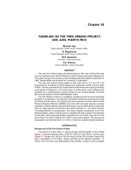
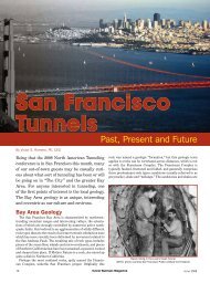
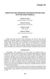
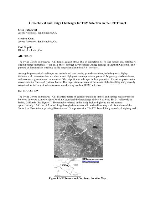
<str<strong>on</strong>g>Geotechnical</str<strong>on</strong>g> <str<strong>on</strong>g>and</str<strong>on</strong>g> <str<strong>on</strong>g>Design</str<strong>on</strong>g> <str<strong>on</strong>g>Challenges</str<strong>on</strong>g> <str<strong>on</strong>g>for</str<strong>on</strong>g> <str<strong>on</strong>g>TBM</str<strong>on</strong>g> <str<strong>on</strong>g>Selecti<strong>on</strong></str<strong>on</strong>g> <strong>on</strong> <strong>the</strong> <strong>ICE</strong> TunnelSteve DubnewychJacobs Associates, San Francisco, CAStephen KleinJacobs Associates, San Francisco, CAPaul GuptillKleinfelder, Irvine, CAABSTRACTThe Irvine-Cor<strong>on</strong>a Expressway (<strong>ICE</strong>) tunnels c<strong>on</strong>sist of two 16.0-m-diameter (52.5-ft) road tunnels <str<strong>on</strong>g>and</str<strong>on</strong>g>, potentially,<strong>on</strong>e rail tunnel extending 17.4 km (11.5 miles) between Riverside <str<strong>on</strong>g>and</str<strong>on</strong>g> Orange counties in Sou<strong>the</strong>rn Cali<str<strong>on</strong>g>for</str<strong>on</strong>g>nia. Thepurpose of <strong>the</strong> tunnels is to relieve traffic c<strong>on</strong>gesti<strong>on</strong> al<strong>on</strong>g <strong>the</strong> SR-91 corridor.Am<strong>on</strong>g <strong>the</strong> geotechnical challenges are variable <str<strong>on</strong>g>and</str<strong>on</strong>g> poor quality ground c<strong>on</strong>diti<strong>on</strong>s, including weak, highlyfractured rock, numerous fault <str<strong>on</strong>g>and</str<strong>on</strong>g> shear z<strong>on</strong>es, high groundwater pressures, potential <str<strong>on</strong>g>for</str<strong>on</strong>g> gassy ground c<strong>on</strong>diti<strong>on</strong>s,<str<strong>on</strong>g>and</str<strong>on</strong>g> a corrosive groundwater envir<strong>on</strong>ment. O<strong>the</strong>r significant challenges include protecti<strong>on</strong> of sensitive groundwaterresources in <strong>the</strong> Clevel<str<strong>on</strong>g>and</str<strong>on</strong>g> Nati<strong>on</strong>al Forest. This paper discusses some of <strong>the</strong> results of <strong>the</strong> feasibility study recentlycompleted <str<strong>on</strong>g>for</str<strong>on</strong>g> <strong>the</strong> project with a focus <strong>on</strong> tunnel boring machine (<str<strong>on</strong>g>TBM</str<strong>on</strong>g>) selecti<strong>on</strong>.INTRODUCTIONThe Irvine-Cor<strong>on</strong>a Expressway (<strong>ICE</strong>) is a transportati<strong>on</strong> corridor including tunnels <str<strong>on</strong>g>and</str<strong>on</strong>g> surface roads proposedbetween Interstate-15 near Cajalco Road in Cor<strong>on</strong>a <str<strong>on</strong>g>and</str<strong>on</strong>g> <strong>the</strong> interchange of <strong>the</strong> SR-133 <str<strong>on</strong>g>and</str<strong>on</strong>g> SR-241 toll roads inIrvine, Cali<str<strong>on</strong>g>for</str<strong>on</strong>g>nia (See Figure 1). The tunnels evaluated in this study include highway <str<strong>on</strong>g>and</str<strong>on</strong>g> rail tunnelsapproximately 17.4 km (11.5 miles) l<strong>on</strong>g through <strong>the</strong> metamorphic <str<strong>on</strong>g>and</str<strong>on</strong>g> sedimentary rock <str<strong>on</strong>g>for</str<strong>on</strong>g>mati<strong>on</strong>s of <strong>the</strong>Santa Ana Mountains separating Riverside <str<strong>on</strong>g>and</str<strong>on</strong>g> Orange counties. The <strong>ICE</strong> Tunnel Study c<strong>on</strong>sidered highway <str<strong>on</strong>g>and</str<strong>on</strong>g>Figure 1. <strong>ICE</strong> Tunnels <str<strong>on</strong>g>and</str<strong>on</strong>g> Coreholes, Locati<strong>on</strong> Map
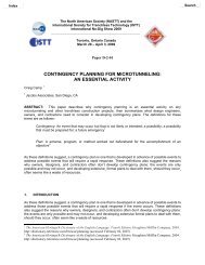
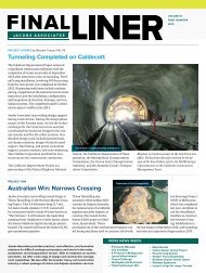
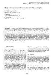
ail c<strong>on</strong>figurati<strong>on</strong>s relieving traffic c<strong>on</strong>gesti<strong>on</strong> <strong>on</strong> <strong>the</strong> SR-91 through Santa Ana Cany<strong>on</strong>. According to Cali<str<strong>on</strong>g>for</str<strong>on</strong>g>niatransportati<strong>on</strong> authorities, traffic is projected to grow so much between now <str<strong>on</strong>g>and</str<strong>on</strong>g> 2030 that <strong>the</strong> SR-91 highway wouldhave to exp<str<strong>on</strong>g>and</str<strong>on</strong>g> from 12 lanes to 22 lanes in order to h<str<strong>on</strong>g>and</str<strong>on</strong>g>le <strong>the</strong> increased dem<str<strong>on</strong>g>and</str<strong>on</strong>g>. The highway tunnels, ifc<strong>on</strong>structed, are expected to remove roughly 60,000 to 70,000 average daily trips (ADT) from SR-91.Funding <str<strong>on</strong>g>for</str<strong>on</strong>g> <strong>the</strong> <strong>ICE</strong> Tunnel feasibility evaluati<strong>on</strong> was secured through <strong>the</strong> Safe, Accountable, Flexible, EfficientTransportati<strong>on</strong> Equity Act―Legacy <str<strong>on</strong>g>for</str<strong>on</strong>g> Users (SAFETEA-LU). This paper summarizes both <strong>the</strong> geotechnicalc<strong>on</strong>diti<strong>on</strong>s to be encountered by <strong>the</strong> tunnels <str<strong>on</strong>g>and</str<strong>on</strong>g> <strong>the</strong> challenges posed to tunnel c<strong>on</strong>structi<strong>on</strong> <str<strong>on</strong>g>and</str<strong>on</strong>g> tunnel boringmachine (<str<strong>on</strong>g>TBM</str<strong>on</strong>g>) selecti<strong>on</strong>.TUNNEL CONCEPTS CONSIDEREDSeveral tunnel c<strong>on</strong>cepts were evaluated, including a deep tunnel c<strong>on</strong>cept <str<strong>on</strong>g>and</str<strong>on</strong>g> a sec<strong>on</strong>d c<strong>on</strong>cept that c<strong>on</strong>sists of acombinati<strong>on</strong> of surface roads <str<strong>on</strong>g>and</str<strong>on</strong>g> tunnels. The combined surface road/ tunnel c<strong>on</strong>cept is likely to present significantenvir<strong>on</strong>mental challenges since <strong>the</strong> surface roads <str<strong>on</strong>g>and</str<strong>on</strong>g> associated c<strong>on</strong>structi<strong>on</strong> activities would take place in <strong>the</strong>Clevel<str<strong>on</strong>g>and</str<strong>on</strong>g> Nati<strong>on</strong>al Forest <str<strong>on</strong>g>and</str<strong>on</strong>g> <strong>on</strong> nearby Irvine Ranch C<strong>on</strong>servancy l<str<strong>on</strong>g>and</str<strong>on</strong>g>. Although this c<strong>on</strong>cept might betechnically possible, it does not seem to be a viable approach at this time.The deep tunnel c<strong>on</strong>cept c<strong>on</strong>sidered four different tunnel c<strong>on</strong>figurati<strong>on</strong>s:1. Twin-bore highway tunnels c<strong>on</strong>nected by emergency cross passages2. A single two-lane reversible directi<strong>on</strong> highway tunnel paired with a single track rail tunnel c<strong>on</strong>nected byemergency cross passages3. Staged c<strong>on</strong>structi<strong>on</strong> of twin-bore, two-lane highway tunnels paired with a single track rail tunnel c<strong>on</strong>nectedby emergency cross passages, with <strong>the</strong> sec<strong>on</strong>d highway tunnel being c<strong>on</strong>structed at a later date4. Three single-lane highway tunnels, two dedicated to <strong>on</strong>e-way traffic <str<strong>on</strong>g>and</str<strong>on</strong>g> <strong>on</strong>e reversible, all c<strong>on</strong>nected byemergency cross passagesThis paper will focus <strong>on</strong> <strong>the</strong> third c<strong>on</strong>figurati<strong>on</strong>, as shown in Figure 2, which includes twin-bore, two-lane highwaytunnels (<strong>the</strong> sec<strong>on</strong>d highway tunnel to be c<strong>on</strong>structed at later date) <str<strong>on</strong>g>and</str<strong>on</strong>g> <strong>on</strong>e rail tunnel, each with a total length ofapproximately 18.5 km (60,000 ft, or 11.5 miles). These tunnels would be c<strong>on</strong>nected to I-15 to <strong>the</strong> east <str<strong>on</strong>g>and</str<strong>on</strong>g> <strong>the</strong> SR-241/SR-133 interchange to <strong>the</strong> west by relatively short secti<strong>on</strong>s of surface highway. Each of <strong>the</strong> two or three tunnelswould have two portals. The tunnel plan <str<strong>on</strong>g>and</str<strong>on</strong>g> profile are shown in Figures 1, 3a, <str<strong>on</strong>g>and</str<strong>on</strong>g> 3b.Figure 2. Tunnel C<strong>on</strong>figurati<strong>on</strong>
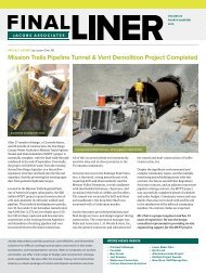
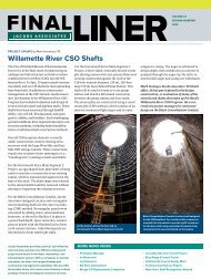
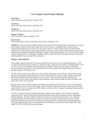
The twin-bore tunnels start at an approximate elevati<strong>on</strong> of 204 m (670 ft) above mean sea level (msl) at <strong>the</strong> WestPortal <str<strong>on</strong>g>and</str<strong>on</strong>g> reach a maximum elevati<strong>on</strong> of 649 m (2,130 ft) msl at approximately Stati<strong>on</strong> 510+00; <strong>the</strong> tunnels end atan approximate elevati<strong>on</strong> of 515 m (1,690 ft) msl at <strong>the</strong> East Portal. The tunnel grade varies al<strong>on</strong>g <strong>the</strong> alignment <str<strong>on</strong>g>and</str<strong>on</strong>g>ranges from 0.1% to 5.0% (although inclusi<strong>on</strong> of a rail tunnel in <strong>the</strong> project will likely limit <strong>the</strong> maximum grade to3%). The ground cover above <strong>the</strong> tunnels ranges from a minimum of 6.1 m (20 ft) at Stati<strong>on</strong> 25+00 to a maximum of408 m (1,340 ft) at Stati<strong>on</strong> 440+00. The minimum tunnel cover under <strong>the</strong> major cany<strong>on</strong>s <str<strong>on</strong>g>and</str<strong>on</strong>g> creeks isapproximately 15.2 m (50 ft).Tunnel size exceeds 15.2 m (50 ft) in diameter, based <strong>on</strong> Caltrans clearance requirements <str<strong>on</strong>g>for</str<strong>on</strong>g> a highway tunnel ofthis length. Assuming two 3.7-m-wide (12-ft) traffic lanes in each bore <str<strong>on</strong>g>and</str<strong>on</strong>g> 1.5 <str<strong>on</strong>g>and</str<strong>on</strong>g> 3 m (5 <str<strong>on</strong>g>and</str<strong>on</strong>g> 10 ft) wide shouldersplus two 1.2 m (4-ft) walkways, a finished tunnel diameter (ID) of approximately 14.5 m (47.5 ft) is required <str<strong>on</strong>g>for</str<strong>on</strong>g> <strong>the</strong>project (Kleinfelder 2009b). Clearances <str<strong>on</strong>g>for</str<strong>on</strong>g> <strong>the</strong> rail tunnel indicate that a finished tunnel diameter of 7.3 m (24 ft) isrequired <str<strong>on</strong>g>for</str<strong>on</strong>g> a single track tunnel. These preliminary clearances have been adopted <str<strong>on</strong>g>for</str<strong>on</strong>g> <strong>the</strong> feasibility study, <str<strong>on</strong>g>and</str<strong>on</strong>g> <strong>the</strong>ywill be revisited in more detailed design studies <str<strong>on</strong>g>for</str<strong>on</strong>g> <strong>the</strong> project.REGIONAL GEOLOGYThe Santa Ana Mountains are <strong>the</strong> nor<strong>the</strong>rn porti<strong>on</strong> of <strong>the</strong> crystalline bedrock Peninsular Ranges that extend southinto Mexico. The nor<strong>the</strong>ast side of <strong>the</strong> Santa Ana Mountains <str<strong>on</strong>g>for</str<strong>on</strong>g>ms a steep scarp that rises from <strong>the</strong> Elsinore <str<strong>on</strong>g>and</str<strong>on</strong>g>Temescal valleys al<strong>on</strong>g <strong>the</strong> active Elsinore fault z<strong>on</strong>e. The western side of <strong>the</strong> Santa Ana Mountains is less abrupt<str<strong>on</strong>g>and</str<strong>on</strong>g> slopes down to <strong>the</strong> Santa Ana Plain (see Figure 3a). The core of <strong>the</strong> Santa Ana Mountains c<strong>on</strong>sists of Mesozoicmetasedimentary <str<strong>on</strong>g>and</str<strong>on</strong>g> igneous rocks that are flanked <strong>on</strong> <strong>the</strong> west by younger Late Cretaceous <str<strong>on</strong>g>and</str<strong>on</strong>g> Tertiary-agedclastic sedimentary rocks (see Figure 3b). The dip of strata in <strong>the</strong> eastern part of <strong>the</strong> Santa Ana Mountains isgenerally steep <str<strong>on</strong>g>and</str<strong>on</strong>g> to <strong>the</strong> east al<strong>on</strong>g <strong>the</strong> tunnel corridor (50 to 70 degrees) but is sometimes near vertical <str<strong>on</strong>g>and</str<strong>on</strong>g> locallyoverturned. The bedding dips of <strong>the</strong> western sedimentary strata are gentler, about 15 to 30 degrees, generallydipping to <strong>the</strong> west, although several anticlines <str<strong>on</strong>g>and</str<strong>on</strong>g> synclines have been mapped within <strong>the</strong> western strata(Schoellhamer et al. 1981).The Santa Ana Mountains c<strong>on</strong>tain numerous faults <str<strong>on</strong>g>and</str<strong>on</strong>g> folds that generally trend northwest-sou<strong>the</strong>ast, parallel to <strong>the</strong>strike of <strong>the</strong> Tertiary sedimentary strata. The majority of <strong>the</strong> mapped faults dem<strong>on</strong>strate a down-to-<strong>the</strong>-westdisplacement (Schoellhamer et al. 1981), although <strong>the</strong> Elsinore fault, which is <strong>the</strong> dominant structural fault in <strong>the</strong>area, dem<strong>on</strong>strates sec<strong>on</strong>dary down-to-<strong>the</strong>-east displacement (i.e., thous<str<strong>on</strong>g>and</str<strong>on</strong>g>s of feet). The predominant structuraldisplacement al<strong>on</strong>g <strong>the</strong> Elsinore fault is right-lateral strike-slip displacement (i.e., tens of miles). The eastern tunnelportals have been strategically placed west of <strong>the</strong> Elsinore fault to avoid potential fault displacement across <strong>the</strong>tunnel.SEISMICITYThe Elsinore fault <str<strong>on</strong>g>for</str<strong>on</strong>g>ms <strong>the</strong> eastern boundary of <strong>the</strong> Santa Ana Mountains. At its nor<strong>the</strong>rn end, <strong>the</strong> Elsinore faultsplays into two branches, <strong>the</strong> Chino fault <str<strong>on</strong>g>and</str<strong>on</strong>g> <strong>the</strong> Whittier fault. The maximum magnitude of an earthquake <strong>on</strong> <strong>the</strong>Elsinore fault is estimated to be M7.1 (Cao et al. 2003). There has <strong>on</strong>ly been <strong>on</strong>e large earthquake <strong>on</strong> <strong>the</strong> Elsinorefault during historical times: <strong>the</strong> earthquake of 1910, an M6 near Temescal Valley, which produced no knownsurface rupture (SCEDC 2008). During <strong>the</strong> field investigati<strong>on</strong>s of this study, <strong>the</strong> M5.4 Chino Hills earthquakeoccurred <strong>on</strong> July 29, 2008, <strong>on</strong> a suspected “blind thrust fault” beneath <strong>the</strong> Puente Hills 25.7 km (16 miles) north of<strong>the</strong> site.FEASIBILITY-LEVEL FIELD INVESTIGATION RESULTSThe purpose of <strong>the</strong> feasibility-level field investigati<strong>on</strong>s was to evaluate geotechnical <str<strong>on</strong>g>and</str<strong>on</strong>g> hydrogeological c<strong>on</strong>diti<strong>on</strong>sin <strong>the</strong> interior of <strong>the</strong> Santa Ana Mountains, where rock <str<strong>on</strong>g>and</str<strong>on</strong>g> groundwater c<strong>on</strong>diti<strong>on</strong>s are least known. There<str<strong>on</strong>g>for</str<strong>on</strong>g>e, <strong>the</strong>investigati<strong>on</strong>s focused <strong>on</strong> <strong>the</strong> eastern half of <strong>the</strong> <strong>ICE</strong> tunnel corridor, where high groundwater pressures <str<strong>on</strong>g>and</str<strong>on</strong>g> highoverburden pressures are expected to define <strong>the</strong> most difficult design <str<strong>on</strong>g>and</str<strong>on</strong>g> c<strong>on</strong>structi<strong>on</strong> challenges. The geologicsetting <str<strong>on</strong>g>and</str<strong>on</strong>g> geotechnical c<strong>on</strong>diti<strong>on</strong> of <strong>the</strong> sedimentary <str<strong>on</strong>g>for</str<strong>on</strong>g>mati<strong>on</strong>s at <strong>the</strong> western end of <strong>the</strong> tunnel has beeninterpreted from <strong>the</strong> literature <str<strong>on</strong>g>and</str<strong>on</strong>g> o<strong>the</strong>r available geotechnical data.
Figure 3a. West ProfileFigure 3b. East Profile
The field investigati<strong>on</strong>s involved five deep coreholes (<strong>ICE</strong>-1, <strong>ICE</strong>-2, <strong>ICE</strong>-3, <strong>ICE</strong>-4 <str<strong>on</strong>g>and</str<strong>on</strong>g> <strong>ICE</strong>-5) completed at selectsites al<strong>on</strong>g <strong>the</strong> <strong>ICE</strong> corridor (see Figure 1). The geotechnical data collected include c<strong>on</strong>tinuous rock core (2,057 m[6,750 ft]); in situ geophysical logs; in situ hydraulic testing; <str<strong>on</strong>g>and</str<strong>on</strong>g> laboratory test data <strong>on</strong> rock samples.In <strong>ICE</strong>-1, <strong>ICE</strong>-2, <str<strong>on</strong>g>and</str<strong>on</strong>g> <strong>ICE</strong>-3, <strong>the</strong> rock mass is composed of <strong>the</strong> Bed<str<strong>on</strong>g>for</str<strong>on</strong>g>d Cany<strong>on</strong> Formati<strong>on</strong> (see Figure 3b), which isa sedimentary flysch deposit c<strong>on</strong>sisting of alternating s<str<strong>on</strong>g>and</str<strong>on</strong>g>st<strong>on</strong>e, argillite, pebbly mudst<strong>on</strong>e, pebble c<strong>on</strong>glomerate,mudst<strong>on</strong>e, <str<strong>on</strong>g>and</str<strong>on</strong>g> shales that have underg<strong>on</strong>e low-grade metamorphism followed by extensive shearing. In <strong>ICE</strong>-4 <str<strong>on</strong>g>and</str<strong>on</strong>g><strong>ICE</strong>-5, <strong>the</strong> Bed<str<strong>on</strong>g>for</str<strong>on</strong>g>d Cany<strong>on</strong> Formati<strong>on</strong> has been locally intruded by <strong>the</strong> Santiago Peak Volcanics, a suite of volcanic<str<strong>on</strong>g>and</str<strong>on</strong>g> shallow plut<strong>on</strong>ic igneous rocks that c<strong>on</strong>sist of basalt, <str<strong>on</strong>g>and</str<strong>on</strong>g>esite, diorite, <str<strong>on</strong>g>and</str<strong>on</strong>g> volcaniclastics that have alsounderg<strong>on</strong>e low-grade metamorphism (see Figure 3b).Data from vibrating-wire piezometers installed in <strong>the</strong> coreholes indicate that groundwater pressures at <strong>the</strong> tunnelinvert range from 0.7 to 2.2 MPa (6.7 to 21.3 bar) after a year of equilibrati<strong>on</strong>. These pressures are less thanexpected, as a c<strong>on</strong>stant hydrostatic pressure gradient from <strong>the</strong> shallowest groundwater elevati<strong>on</strong> to tunnel depthwould result in pressures of 3.4 MPa (33.3 bar). Lower pressures are advantageous <str<strong>on</strong>g>for</str<strong>on</strong>g> tunneling <str<strong>on</strong>g>and</str<strong>on</strong>g> tunnel liningdesign; however, peizometer readings may vary seas<strong>on</strong>ally, <str<strong>on</strong>g>and</str<strong>on</strong>g> l<strong>on</strong>g-term m<strong>on</strong>itoring is required to c<strong>on</strong>firm <strong>the</strong>seinitial findings.The RQD values <str<strong>on</strong>g>for</str<strong>on</strong>g> 2,057 m (6,750 ft) of core do not exhibit a str<strong>on</strong>g dependency up<strong>on</strong> lithology or depth (seeFigure 4). Observed trends in <strong>the</strong> RQD do change c<strong>on</strong>siderably with corehole locati<strong>on</strong>, however. For example, at<strong>ICE</strong>-1, <strong>ICE</strong>-2 <str<strong>on</strong>g>and</str<strong>on</strong>g> <strong>ICE</strong>-3, approximately 90% of <strong>the</strong> RQD values are less than Fair (RQD 35,000 psi]). The interbedded metas<str<strong>on</strong>g>and</str<strong>on</strong>g>st<strong>on</strong>e <str<strong>on</strong>g>and</str<strong>on</strong>g> argillite ranges from weak tovery str<strong>on</strong>g (5 to >100 MPa; 750 to >15,000 psi). Strengths of <strong>the</strong> pebbly mudst<strong>on</strong>es of <strong>the</strong> Bed<str<strong>on</strong>g>for</str<strong>on</strong>g>d Cany<strong>on</strong>Formati<strong>on</strong> ranges from very weak to moderately str<strong>on</strong>g (1 to 50 MPa [150 to 7,500 psi]). The intact strength of <strong>the</strong>Santiago Peak Volcanics (diorite) also ranges widely from moderately str<strong>on</strong>g to very str<strong>on</strong>g (25 to 250 MPa [3,500to 35,000 psi]). No testing of <strong>the</strong> sedimentary <str<strong>on</strong>g>for</str<strong>on</strong>g>mati<strong>on</strong>s in <strong>the</strong> West Tunnel Segment was c<strong>on</strong>ducted under thisstudy, but <str<strong>on</strong>g>for</str<strong>on</strong>g>mati<strong>on</strong>s are estimated to range from extremely weak (e.g., shales) to moderately str<strong>on</strong>g (shales,s<str<strong>on</strong>g>and</str<strong>on</strong>g>st<strong>on</strong>e, <str<strong>on</strong>g>and</str<strong>on</strong>g> c<strong>on</strong>glomerate) based <strong>on</strong> general lithology <str<strong>on</strong>g>and</str<strong>on</strong>g> strength-test results <strong>on</strong> rock cores from nearby projects(i.e., Bowerman L<str<strong>on</strong>g>and</str<strong>on</strong>g>fill <str<strong>on</strong>g>and</str<strong>on</strong>g> SR-241 Toll Road).
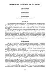
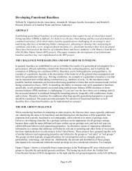
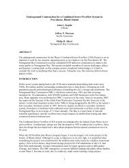
Rock mass classificati<strong>on</strong> systems indicate generally poor rock c<strong>on</strong>diti<strong>on</strong>s <str<strong>on</strong>g>for</str<strong>on</strong>g> tunneling in <strong>the</strong> Bed<str<strong>on</strong>g>for</str<strong>on</strong>g>d Cany<strong>on</strong>Formati<strong>on</strong> <str<strong>on</strong>g>and</str<strong>on</strong>g> <strong>the</strong> Santiago Peak Volcanics, as suggested by RMR, Q, <str<strong>on</strong>g>and</str<strong>on</strong>g> GSI indicators. From 9,315 calculatedRMR values, <strong>the</strong> rock mass character can be described as Poor to Fair rock, with more than 85% of <strong>the</strong> RMR valueswithin <strong>the</strong> ranges defined by <strong>the</strong>se two categories (21 < RMR < 60) (see Figure 5). From 3,056 calculated Q values,nearly 84% of <strong>the</strong> Q values occur in <strong>the</strong> Extremely Poor to Very Poor (0.004 < Q < 1) rock mass classes (see Figure5). Figure 6 illustrates RMR versus Q values <str<strong>on</strong>g>for</str<strong>on</strong>g> <strong>the</strong> rock within <strong>the</strong> tunnel envelope <strong>on</strong>ly (15.2 m [50 ft] envelope).Nearly 83% of <strong>the</strong> GSI values <str<strong>on</strong>g>for</str<strong>on</strong>g> <strong>the</strong> entire rock core are less than Fair (GSI < 41) (see Figure 5).The in situ hydraulic c<strong>on</strong>ductivity testing (i.e., packer testing) indicates that effective hydraulic c<strong>on</strong>ductivities at <strong>the</strong><strong>ICE</strong> Tunnel envelope depths are <strong>on</strong> <strong>the</strong> order of 2.5E-05 cm/sec (Corehole <strong>ICE</strong>-1 between 198.7 <str<strong>on</strong>g>and</str<strong>on</strong>g> 228.8 m [652.1<str<strong>on</strong>g>and</str<strong>on</strong>g> 750.6 ft] beneath ground surface [bgs]) to 2.9E-08 cm/sec (Corehole <strong>ICE</strong>-5 at 328.5 to 352.9 m [1,077.9 to1,157.9 ft] bgs). The data suggest low groundwater inflows during tunneling in <strong>the</strong> Bed<str<strong>on</strong>g>for</str<strong>on</strong>g>d Cany<strong>on</strong> Formati<strong>on</strong> <str<strong>on</strong>g>and</str<strong>on</strong>g><strong>the</strong> Santiago Peak Volcanics, although localized higher inflows should be expected.Groundwater C<strong>on</strong>diti<strong>on</strong>sPotentially adverse geochemistry of <strong>the</strong> Bed<str<strong>on</strong>g>for</str<strong>on</strong>g>d Cany<strong>on</strong> Formati<strong>on</strong> includes an abundance of sulfides, includingpyrite, marcasite, <str<strong>on</strong>g>and</str<strong>on</strong>g> chalcopyrite yielding hydrogen sulfide gas noticeable during field explorati<strong>on</strong>. Additi<strong>on</strong>ally,field testing of water samples from two mountain springs yielded pH readings as low 2.8 <str<strong>on</strong>g>and</str<strong>on</strong>g> 3.5; however, <strong>the</strong>majority of readings are in <strong>the</strong> neutral pH range.Geologic ProfileThe <strong>ICE</strong> Tunnels have been subdivided into a West <str<strong>on</strong>g>and</str<strong>on</strong>g> East Tunnel Segments based up<strong>on</strong> <strong>the</strong> anticipated geologic<str<strong>on</strong>g>and</str<strong>on</strong>g> groundwater c<strong>on</strong>diti<strong>on</strong>s (see Figures 3a <str<strong>on</strong>g>and</str<strong>on</strong>g> 3b).West Tunnel Segment (Sta 000+00 to 322+00)The West Segment of <strong>the</strong> <strong>ICE</strong> Tunnels is anticipated to be located in sedimentary rocks that c<strong>on</strong>sist of shale,s<str<strong>on</strong>g>and</str<strong>on</strong>g>st<strong>on</strong>e, <str<strong>on</strong>g>and</str<strong>on</strong>g> c<strong>on</strong>glomerate that are estimated to be extremely weak to moderately str<strong>on</strong>g <str<strong>on</strong>g>and</str<strong>on</strong>g> under moderatehydrostatic pressure 0 to 0.5 MPa (0 to 5 bar), with most below 0.3 MPa (3 bar). The geologic <str<strong>on</strong>g>and</str<strong>on</strong>g> hydrogeologicc<strong>on</strong>diti<strong>on</strong>s al<strong>on</strong>g <strong>the</strong> West Segment corridor are expected to be fairly uni<str<strong>on</strong>g>for</str<strong>on</strong>g>m but with local shearing al<strong>on</strong>g bedding<str<strong>on</strong>g>and</str<strong>on</strong>g> at a few mapped fault z<strong>on</strong>es. When tunneling through <strong>the</strong> West Segment, <strong>the</strong> ground is expected to be slow tofast raveling because many of <strong>the</strong>se geologic <str<strong>on</strong>g>for</str<strong>on</strong>g>mati<strong>on</strong>s are anticipated to be soft or weakly cemented. Some of <strong>the</strong><str<strong>on</strong>g>for</str<strong>on</strong>g>mati<strong>on</strong>s may exhibit soil-like behavior during tunneling, <str<strong>on</strong>g>and</str<strong>on</strong>g> flowing c<strong>on</strong>diti<strong>on</strong>s could be encountered in isolatedareas where <strong>the</strong> sedimentary <str<strong>on</strong>g>for</str<strong>on</strong>g>mati<strong>on</strong>s are uncemented <str<strong>on</strong>g>and</str<strong>on</strong>g> <strong>the</strong> tunnel is below groundwater. The potential <str<strong>on</strong>g>for</str<strong>on</strong>g>groundwater inflows generally ranges from low to moderately low <strong>on</strong> <strong>the</strong> basis of <strong>the</strong> anticipated rock types.According to published geologic maps (Schoellhamer et al. 1981) three fault traces have been identified. Squeezingground c<strong>on</strong>diti<strong>on</strong>s could be associated with <strong>the</strong>se faults because <strong>the</strong> rock mass is weakened significantly. Also,groundwater inflows can be high in fault z<strong>on</strong>es because of <strong>the</strong> increase in fracturing typically associated with faultactivity.East Tunnel Segment (Sta 322+00 to 602+25)The East Segment runs through <strong>the</strong> core of <strong>the</strong> Santa Ana Mountains, <str<strong>on</strong>g>and</str<strong>on</strong>g> at tunnel depth is expected to encounterigneous <str<strong>on</strong>g>and</str<strong>on</strong>g> sedimentary to metasedimentary rocks under potential hydrostatic pressures up to 2.1 MPa (21 bar).Ground c<strong>on</strong>diti<strong>on</strong>s are inherently variable in terms of lithology <str<strong>on</strong>g>and</str<strong>on</strong>g> compositi<strong>on</strong>. Some lithologies are extremelyweak, while o<strong>the</strong>rs have intact rock strengths that are extremely str<strong>on</strong>g. Ground c<strong>on</strong>diti<strong>on</strong>s are expected to rangefrom massive to blocky <str<strong>on</strong>g>and</str<strong>on</strong>g> seamy to raveling. Potential squeezing c<strong>on</strong>diti<strong>on</strong>s are expected in sheared <str<strong>on</strong>g>and</str<strong>on</strong>g> faultz<strong>on</strong>es where <strong>the</strong> overburden is thick, <str<strong>on</strong>g>and</str<strong>on</strong>g> interbeds where <strong>the</strong> rock mass is predominantly argillite or pebblymudst<strong>on</strong>e.
Figure 5. RMR, Q, <str<strong>on</strong>g>and</str<strong>on</strong>g> GSI by Lithology
PROJECT CONSTRUCTION CHALLENGESFigure 6. RMR vs. QThe entire study area crosses a complex geologic z<strong>on</strong>e with variable ground c<strong>on</strong>diti<strong>on</strong>s ranging from sedimentaryrock under relatively low groundwater pressures in <strong>the</strong> west to volcanic <str<strong>on</strong>g>and</str<strong>on</strong>g> metasedimentary rock under highgroundwater pressures to <strong>the</strong> east. Potential design <str<strong>on</strong>g>and</str<strong>on</strong>g> c<strong>on</strong>structi<strong>on</strong> challenges that are related to <strong>the</strong> geotechnicalc<strong>on</strong>diti<strong>on</strong>s include:• Variable <str<strong>on</strong>g>and</str<strong>on</strong>g> difficult ground c<strong>on</strong>diti<strong>on</strong>s• High external water pressures• Gassy ground• Corrosive groundwaterO<strong>the</strong>r significant design challenges include lining design <str<strong>on</strong>g>and</str<strong>on</strong>g> protecti<strong>on</strong> of groundwater resources.Variable <str<strong>on</strong>g>and</str<strong>on</strong>g> Difficult Ground C<strong>on</strong>diti<strong>on</strong>sBecause of <strong>the</strong> potentially l<strong>on</strong>g tunnel lengths, a broad range of ground c<strong>on</strong>diti<strong>on</strong>s may be encountered al<strong>on</strong>g <strong>the</strong>tunnel alignments. A particularly undesirable c<strong>on</strong>diti<strong>on</strong> is a mixed face c<strong>on</strong>diti<strong>on</strong> where <strong>the</strong> face is in both rock <str<strong>on</strong>g>and</str<strong>on</strong>g>soft ground or several materials of widely differing density <str<strong>on</strong>g>and</str<strong>on</strong>g> hardness. However, a given <str<strong>on</strong>g>TBM</str<strong>on</strong>g> will generallyper<str<strong>on</strong>g>for</str<strong>on</strong>g>m optimally in a relatively narrow range of ground c<strong>on</strong>diti<strong>on</strong>s. If <strong>the</strong> rock has very high strength, <strong>the</strong> <str<strong>on</strong>g>TBM</str<strong>on</strong>g>may be designed <str<strong>on</strong>g>for</str<strong>on</strong>g> efficient mining of <strong>the</strong> str<strong>on</strong>g rock, but will be less effective in mining poor quality rock. Theopposite can also be true. For <strong>the</strong> <strong>ICE</strong> tunnels, <strong>the</strong> overall best per<str<strong>on</strong>g>for</str<strong>on</strong>g>mance may be achieved by tailoring <strong>the</strong> <str<strong>on</strong>g>TBM</str<strong>on</strong>g>to address <strong>the</strong> intensely fractured rock c<strong>on</strong>diti<strong>on</strong>s that are currently estimated to comprise at least 53% of <strong>the</strong>alignment in <strong>the</strong> metamorphic terrain (approximately 9.7 km [6 miles]).To overcome <strong>the</strong>se challenging ground c<strong>on</strong>diti<strong>on</strong>s <str<strong>on</strong>g>and</str<strong>on</strong>g> behaviors, <strong>the</strong> <str<strong>on</strong>g>TBM</str<strong>on</strong>g> should be designed with <strong>the</strong>sec<strong>on</strong>siderati<strong>on</strong>s:• The muck h<str<strong>on</strong>g>and</str<strong>on</strong>g>ling should be compatible with high water inflows <str<strong>on</strong>g>and</str<strong>on</strong>g> weak ground, <str<strong>on</strong>g>and</str<strong>on</strong>g> be able toefficiently collect <strong>the</strong> material under all c<strong>on</strong>diti<strong>on</strong>s.• The <str<strong>on</strong>g>TBM</str<strong>on</strong>g> should have excepti<strong>on</strong>al thrust capacity to overcome high ground loads or muck-packingc<strong>on</strong>diti<strong>on</strong>s.
• The cutterhead should be able to limit or c<strong>on</strong>trol <strong>the</strong> flow of material through <strong>the</strong> head (both from <strong>the</strong>outside through <strong>the</strong> head or out of <strong>the</strong> head) <str<strong>on</strong>g>and</str<strong>on</strong>g> aid in maintaining face support under weak groundc<strong>on</strong>diti<strong>on</strong>s.• The <str<strong>on</strong>g>TBM</str<strong>on</strong>g> should be able to maintain line <str<strong>on</strong>g>and</str<strong>on</strong>g> grade in variable ground, including weak ground, <str<strong>on</strong>g>and</str<strong>on</strong>g> incurves.• In squeezing ground c<strong>on</strong>diti<strong>on</strong>s, special design provisi<strong>on</strong>s should be included, such as increasing <strong>the</strong>overcut, lubricating <strong>the</strong> <str<strong>on</strong>g>TBM</str<strong>on</strong>g> shield skin, reducing <strong>the</strong> <str<strong>on</strong>g>TBM</str<strong>on</strong>g> shield length, using a tapered shield, limiting<str<strong>on</strong>g>TBM</str<strong>on</strong>g> stops at critical stati<strong>on</strong>s, m<strong>on</strong>itoring tunnel de<str<strong>on</strong>g>for</str<strong>on</strong>g>mati<strong>on</strong> <str<strong>on</strong>g>and</str<strong>on</strong>g> earth pressure, <str<strong>on</strong>g>and</str<strong>on</strong>g> having <strong>the</strong> ability toflush out material from <strong>the</strong> annulus back towards <strong>the</strong> cutterhead.Technological advancements <str<strong>on</strong>g>and</str<strong>on</strong>g> additi<strong>on</strong>al practical experience with hybrid-style <str<strong>on</strong>g>TBM</str<strong>on</strong>g>s may eventually improve<strong>the</strong> per<str<strong>on</strong>g>for</str<strong>on</strong>g>mance of <strong>the</strong> <str<strong>on</strong>g>TBM</str<strong>on</strong>g> <str<strong>on</strong>g>for</str<strong>on</strong>g> <strong>the</strong> anticipated c<strong>on</strong>diti<strong>on</strong>s of <strong>the</strong> <strong>ICE</strong> project.High External Water PressuresThe maximum groundwater head is expected to be in excess of 2 MPa (20 bar). Excavating a tunnel under pressuresof this magnitude presents health <str<strong>on</strong>g>and</str<strong>on</strong>g> safety hazards as well as challenges in designing a machine <str<strong>on</strong>g>and</str<strong>on</strong>g> initial liningto withst<str<strong>on</strong>g>and</str<strong>on</strong>g> <strong>the</strong> pressure. While tunneling under pressures of 0.4 MPa (4 bar) is routinely per<str<strong>on</strong>g>for</str<strong>on</strong>g>med, pressures inexcess of 0.5 MPa (5 bar) <str<strong>on</strong>g>for</str<strong>on</strong>g> this size of excavati<strong>on</strong> will require state-of-<strong>the</strong>-art techniques. It should be noted that itwould not be possible to operate a <str<strong>on</strong>g>TBM</str<strong>on</strong>g> with a closed, pressurized face under such high water pressure, as <strong>the</strong>machine could not be pushed <str<strong>on</strong>g>for</str<strong>on</strong>g>ward against such pressure. The current c<strong>on</strong>cept is that <strong>the</strong> tunnels would be minedusing a slurry <str<strong>on</strong>g>TBM</str<strong>on</strong>g>. Under this c<strong>on</strong>cept, in areas of lower groundwater pressure <strong>the</strong> heading area would bepressurized to c<strong>on</strong>trol <strong>the</strong> potential water inflows <str<strong>on</strong>g>and</str<strong>on</strong>g> <strong>the</strong> primary lining would be erected <str<strong>on</strong>g>and</str<strong>on</strong>g> grouted in placewithin <strong>the</strong> rear of <strong>the</strong> <str<strong>on</strong>g>TBM</str<strong>on</strong>g>.Recognizing that water inflow through some fractures, faults, <str<strong>on</strong>g>and</str<strong>on</strong>g> shear z<strong>on</strong>es could potentially exceed <strong>the</strong> <str<strong>on</strong>g>TBM</str<strong>on</strong>g>’scapacity to c<strong>on</strong>trol water inflows, <strong>the</strong> <str<strong>on</strong>g>TBM</str<strong>on</strong>g>s will have to incorporate provisi<strong>on</strong>s to per<str<strong>on</strong>g>for</str<strong>on</strong>g>m systematic probing (i.e.,drilling ahead of <strong>the</strong> advancing <str<strong>on</strong>g>TBM</str<strong>on</strong>g>), <str<strong>on</strong>g>and</str<strong>on</strong>g> pre-excavati<strong>on</strong> grouting ahead of <strong>the</strong> <str<strong>on</strong>g>TBM</str<strong>on</strong>g>. Systematic probing ahead of<strong>the</strong> tunnel face with probe holes will be required al<strong>on</strong>g <strong>the</strong> tunnel alignment where significant inflows may occur inorder to mitigate <strong>the</strong> risk of encountering high flush flows that might exceed <strong>the</strong> water h<str<strong>on</strong>g>and</str<strong>on</strong>g>ling capacity of <strong>the</strong><str<strong>on</strong>g>TBM</str<strong>on</strong>g>. Probing may also be used to detect areas of weak, unstable ground. When <strong>the</strong>se c<strong>on</strong>diti<strong>on</strong>s are found, <str<strong>on</strong>g>TBM</str<strong>on</strong>g>operati<strong>on</strong> procedures may be modified or pretreatment may be warranted. Various methods can be employed to alter<strong>the</strong> operati<strong>on</strong> of <strong>the</strong> <str<strong>on</strong>g>TBM</str<strong>on</strong>g>, such as closed or pressurized mode, to enhance its compatibility with unfavorable wateror ground c<strong>on</strong>diti<strong>on</strong>s. Pretreatment may include reducing <strong>the</strong> driving head through drainage of <strong>the</strong> groundwater toreduce impacts <strong>on</strong> <strong>the</strong> tunneling operati<strong>on</strong>s, or per<str<strong>on</strong>g>for</str<strong>on</strong>g>ming pre-excavati<strong>on</strong> grouting ahead of <strong>the</strong> <str<strong>on</strong>g>TBM</str<strong>on</strong>g>. Tosufficiently treat <strong>the</strong> problem areas ahead of <strong>the</strong> tunnel, <strong>the</strong> <str<strong>on</strong>g>TBM</str<strong>on</strong>g> will need to have a sufficient number of ports(openings) around <strong>the</strong> circumference of <strong>the</strong> machine to facilitate drilling grout holes ahead of <strong>the</strong> face. Alternativeaccess ports through <strong>the</strong> <str<strong>on</strong>g>TBM</str<strong>on</strong>g> shield or c<strong>on</strong>crete segments fur<strong>the</strong>r back from <strong>the</strong> face facilitate treatment of <strong>the</strong> rockmass surrounding <strong>the</strong> <str<strong>on</strong>g>TBM</str<strong>on</strong>g> or immediately at or ahead of <strong>the</strong> tunnel face. Having an enhanced level of accessibilityadds flexibility <str<strong>on</strong>g>and</str<strong>on</strong>g> opti<strong>on</strong>s to <strong>the</strong> treatment of groundwater <str<strong>on</strong>g>and</str<strong>on</strong>g> ground behavior problems.Interventi<strong>on</strong>s will need to be per<str<strong>on</strong>g>for</str<strong>on</strong>g>med both routinely (planned interventi<strong>on</strong>s) <str<strong>on</strong>g>and</str<strong>on</strong>g> when <strong>the</strong> progress of <strong>the</strong> <str<strong>on</strong>g>TBM</str<strong>on</strong>g> isslower than expected (due to worn cutters). To access <strong>the</strong> cutterhead <str<strong>on</strong>g>for</str<strong>on</strong>g> maintenance while tunneling in closedmode, <strong>the</strong> interventi<strong>on</strong>s will need to be per<str<strong>on</strong>g>for</str<strong>on</strong>g>med under free air, compressed air, or a mixed-gas envir<strong>on</strong>ment.In locati<strong>on</strong>s where interventi<strong>on</strong>s need to occur under high pressures (e.g., blocky <str<strong>on</strong>g>and</str<strong>on</strong>g> seamy <str<strong>on</strong>g>and</str<strong>on</strong>g> crushed rock ,sheared or faulted ground with high permeability), compressed air <str<strong>on</strong>g>and</str<strong>on</strong>g>/or mixed gas may be required; however, <str<strong>on</strong>g>for</str<strong>on</strong>g>interventi<strong>on</strong>s under high head in rock, <strong>the</strong> rock should be stable enough <str<strong>on</strong>g>for</str<strong>on</strong>g> <strong>the</strong> per<str<strong>on</strong>g>for</str<strong>on</strong>g>mance of interventi<strong>on</strong>s in freeair.Additi<strong>on</strong>ally, ground improvement methods could be employed to reduce or eliminate <strong>the</strong> need <str<strong>on</strong>g>for</str<strong>on</strong>g> compressedair by making <strong>the</strong> surrounding ground more stable. Depending <strong>on</strong> <strong>the</strong> pressures expected, <strong>the</strong> <str<strong>on</strong>g>TBM</str<strong>on</strong>g> may need to befitted with a decompressi<strong>on</strong> chamber.Corrosive GroundwaterDuring <strong>the</strong> groundwater m<strong>on</strong>itoring program water samples were chemically tested, <str<strong>on</strong>g>and</str<strong>on</strong>g> two spring/streamm<strong>on</strong>itoring sites in <strong>the</strong> middle <str<strong>on</strong>g>for</str<strong>on</strong>g>k of Ladd Cany<strong>on</strong> exhibited pH levels of less than 5.5. The results of an acidgenerati<strong>on</strong> potential test per<str<strong>on</strong>g>for</str<strong>on</strong>g>med during <strong>the</strong> geotechnical investigati<strong>on</strong> (Kleinfelder 2009a) indicated intrinsicbuffering capacity in a composited, sulfide-rich core sample. The buffering capacity is attributable to <strong>the</strong>
neutralizing acti<strong>on</strong> of calcite in <strong>the</strong> rock mass. There<str<strong>on</strong>g>for</str<strong>on</strong>g>e, it is anticipated that water collected during <strong>the</strong> tunnelexcavati<strong>on</strong> will have acidic properties al<strong>on</strong>g certain porti<strong>on</strong>s of <strong>the</strong> alignment. The corrosi<strong>on</strong> potential of such watershould be c<strong>on</strong>sidered with regards to <strong>the</strong> design, operati<strong>on</strong>, <str<strong>on</strong>g>and</str<strong>on</strong>g> maintenance of <strong>the</strong> <str<strong>on</strong>g>TBM</str<strong>on</strong>g>; health <str<strong>on</strong>g>and</str<strong>on</strong>g> safety of <strong>the</strong>crew; <str<strong>on</strong>g>and</str<strong>on</strong>g> <strong>the</strong> design of <strong>the</strong> ground support systems within <strong>the</strong> tunnel.Gassy Ground C<strong>on</strong>diti<strong>on</strong>sWithin <strong>the</strong> <strong>ICE</strong> tunnel corridor, <strong>the</strong> lignitic shales of <strong>the</strong> Silverado Formati<strong>on</strong> (Tsi) are a potential source of methanegas (see Figure 3a). Methane (CH 4 ) is <strong>the</strong> most comm<strong>on</strong> gas that occurs within gassy ground, <str<strong>on</strong>g>and</str<strong>on</strong>g> it is both highlyflammable <str<strong>on</strong>g>and</str<strong>on</strong>g> an asphyxiant. The lower explosive limit (LEL) of methane is 5% by volume, while <strong>the</strong> upperexplosive limit (UEL) is 15% by volume (Kissell 2006). According to <strong>the</strong> Cali<str<strong>on</strong>g>for</str<strong>on</strong>g>nia Code of Regulati<strong>on</strong>s (CCR), amethane c<strong>on</strong>centrati<strong>on</strong> greater than 0.25% by volume near any surface within <strong>the</strong> tunnel would warrant a gassyground classificati<strong>on</strong>.The potential <str<strong>on</strong>g>for</str<strong>on</strong>g> hydrogen sulfide gas is inferred from several intervals of Santiago Peak Volcanics <str<strong>on</strong>g>and</str<strong>on</strong>g> Bed<str<strong>on</strong>g>for</str<strong>on</strong>g>dCany<strong>on</strong> Formati<strong>on</strong> that c<strong>on</strong>tained abundant sulfide metals (i.e., pyrite), <str<strong>on</strong>g>and</str<strong>on</strong>g> from <strong>the</strong> str<strong>on</strong>g sulfurous odor noted in<strong>the</strong> explorati<strong>on</strong> boreholes (Kleinfelder 2009a). Hydrogen sulfide (H 2 S) has a str<strong>on</strong>g odor similar to rotten eggs <str<strong>on</strong>g>and</str<strong>on</strong>g> isboth corrosive <str<strong>on</strong>g>and</str<strong>on</strong>g> toxic. Hydrogen sulfide gas is also combustible, but at c<strong>on</strong>centrati<strong>on</strong>s that are much higher than<strong>the</strong> 0.1% c<strong>on</strong>centrati<strong>on</strong> that is toxic (Doyle 2001).On <strong>the</strong> basis of <strong>the</strong> findings from <strong>the</strong> <strong>ICE</strong> <str<strong>on</strong>g>Geotechnical</str<strong>on</strong>g> Report (Kleinfelder 2008), <strong>the</strong> <strong>ICE</strong> tunnel corridor willlikely be classified as “gassy” or “potentially gassy” ground according to Cali<str<strong>on</strong>g>for</str<strong>on</strong>g>nia Occupati<strong>on</strong>al Safety <str<strong>on</strong>g>and</str<strong>on</strong>g> HealthAdministrati<strong>on</strong> (Cal/OSHA) criteria because of <strong>the</strong> presence of methane <str<strong>on</strong>g>and</str<strong>on</strong>g> hydrogen sulfide. In <strong>the</strong>se c<strong>on</strong>diti<strong>on</strong>s, aslurry <str<strong>on</strong>g>TBM</str<strong>on</strong>g> would be advantageous since it operates in a “closed circuit,” minimizing workers’ exposure to gasunderground. Also, a slurry <str<strong>on</strong>g>TBM</str<strong>on</strong>g> provides more safety <str<strong>on</strong>g>for</str<strong>on</strong>g> <strong>the</strong> expected high pressures, especially in cohesi<strong>on</strong>lessground.OTHER SIGNIFICANT DESIGN CONSIDERATIONLining <str<strong>on</strong>g>Design</str<strong>on</strong>g>The permanent tunnel lining will need to be watertight in order to avoid any l<strong>on</strong>g-term adverse impacts <strong>on</strong>groundwater levels in <strong>the</strong> Santa Ana Mountains. The proposed deep tunnels linking Riverside County to OrangeCounty will be c<strong>on</strong>structed using a <str<strong>on</strong>g>TBM</str<strong>on</strong>g> <str<strong>on</strong>g>and</str<strong>on</strong>g> will require <strong>the</strong> installati<strong>on</strong> of a permanent watertight lining to c<strong>on</strong>trolgroundwater inflows into <strong>the</strong> tunnel. To achieve a watertight lining, a segmental precast c<strong>on</strong>crete lining withgasketed joints will need to be used. Such linings were designed to withst<str<strong>on</strong>g>and</str<strong>on</strong>g> groundwater pressures up to almost2.7 MPa (392 psi) <str<strong>on</strong>g>for</str<strong>on</strong>g> <strong>the</strong> Arrowhead Tunnels project near San Bernardino (Swartz et al. 2002). A two-pass liningwould require an excavated diameter that exceeds <strong>the</strong> current state of <strong>the</strong> art design <str<strong>on</strong>g>for</str<strong>on</strong>g> <str<strong>on</strong>g>TBM</str<strong>on</strong>g>s.Soil structure interacti<strong>on</strong> methods were used to develop design c<strong>on</strong>cepts <str<strong>on</strong>g>for</str<strong>on</strong>g> <strong>the</strong> tunnel linings. The tunnel lining wasanalyzed at a secti<strong>on</strong> al<strong>on</strong>g <strong>the</strong> alignment corresp<strong>on</strong>ding to <strong>the</strong> highest water pressure (approximately 244 m [800ft]), as well as squeezing ground loads. Lining analyses were per<str<strong>on</strong>g>for</str<strong>on</strong>g>med <str<strong>on</strong>g>for</str<strong>on</strong>g> 762 mm (30 in.) <str<strong>on</strong>g>and</str<strong>on</strong>g> 914 mm (36 in.)segment thicknesses. Results of <strong>the</strong> tunnel lining analyses indicating anticipated lining thickness <str<strong>on</strong>g>and</str<strong>on</strong>g> c<strong>on</strong>cretestrength are summarized in Table 1.Table 1. Results of Lining Analyses <str<strong>on</strong>g>for</str<strong>on</strong>g> Roadway TunnelsTunnel Reach Groundwater HeadC<strong>on</strong>crete Strength762 mm (30 in.) Thick Segment 914 mm (36 in.) Thick Segment0+00 to 323+600 to 49 mClass I Lining(0 to 160 ft) 41.3 to 55.2 MPa (6,000 to 8,000 psi) Class I Lining323+60 to 344+500 to 195 mClass II Lining41.3 to 55.2 MPa (6,000 to 8,000 psi)(0 to 640 ft) 55.2 to 96.5 MPa (8,000 to 14,000 psi)344+50 to 540+00110 to 244 mClass III LiningClass II Lining(360 to 800 ft) 96.5 to 117.2 MPa (14,000 to 17,000 psi) 55.2 to 96.5 MPa (8,000 to 14,000 psi)540+00 to 596+00104 to 460 mClass II Lining(340 to 460 ft) 55.2 to 96.5 MPa (8,000 to 14,000 psi) Class I Lining596+00 to 606+25 0 m (0 ft)Class I Lining41.3 to 55.2 MPa (6,000 to 8,000 psi)41.3 to 55.2 MPa (6,000 to 8,000 psi)
Local c<strong>on</strong>crete suppliers indicate that precast c<strong>on</strong>crete with 56- to 90-day unc<strong>on</strong>fined compressive strengths rangingbetween 89.6 <str<strong>on</strong>g>and</str<strong>on</strong>g> 96.5 MPa (13,000 <str<strong>on</strong>g>and</str<strong>on</strong>g> 14,000 psi) are readily achievable <str<strong>on</strong>g>and</str<strong>on</strong>g> that 117.2 MPa (17,000 psi) isfeasible with materials available in sou<strong>the</strong>rn Cali<str<strong>on</strong>g>for</str<strong>on</strong>g>nia. Strengths up to about 137.9 MPa (20,000 psi) are apossibility, but higher quality aggregates from sources outside Cali<str<strong>on</strong>g>for</str<strong>on</strong>g>nia may be required. In additi<strong>on</strong> to highqualityaggregates, o<strong>the</strong>r key factors in producing high strength c<strong>on</strong>crete include a low water-cement ratio, highqualitycement, additives such as silica fume <str<strong>on</strong>g>and</str<strong>on</strong>g> super plasticizers to improve workability, <str<strong>on</strong>g>and</str<strong>on</strong>g> a very high degreeof quality c<strong>on</strong>trol. Premium costs are associated with <strong>the</strong>se high strength c<strong>on</strong>cretes. Factoring in <strong>the</strong> cost ofmaterials, additives, <str<strong>on</strong>g>and</str<strong>on</strong>g> an increased level of quality c<strong>on</strong>trol, <strong>the</strong> cost of 117.2 to 137.9 MPa (17,000 to 20,000 psi)c<strong>on</strong>crete is approximately three times <strong>the</strong> cost of 41.4 MPa (6,000 psi) c<strong>on</strong>crete, <str<strong>on</strong>g>and</str<strong>on</strong>g> 96.5 MPa (14,000 psi) c<strong>on</strong>creteis approximately twice as expensive as 41.4 MPa (6,000 psi) c<strong>on</strong>crete.Protecti<strong>on</strong> of Groundwater ResourcesThe majority of <strong>the</strong> <strong>ICE</strong> tunnel alignments will be located beneath <strong>the</strong> Clevel<str<strong>on</strong>g>and</str<strong>on</strong>g> Nati<strong>on</strong>al Forest <str<strong>on</strong>g>and</str<strong>on</strong>g> private l<str<strong>on</strong>g>and</str<strong>on</strong>g>sadjacent to <strong>the</strong> western <str<strong>on</strong>g>for</str<strong>on</strong>g>est boundary. In additi<strong>on</strong>, <str<strong>on</strong>g>for</str<strong>on</strong>g> <strong>the</strong> most part <strong>the</strong> proposed tunnels will be c<strong>on</strong>structedbeneath <strong>the</strong> groundwater table. As a result, <strong>the</strong> tunnels have <strong>the</strong> potential to drain groundwater from <strong>the</strong> rock mass,<str<strong>on</strong>g>and</str<strong>on</strong>g> perhaps adversely affect water resources available to <strong>the</strong> overlying l<str<strong>on</strong>g>and</str<strong>on</strong>g>. The extent to which drainage mayoccur during c<strong>on</strong>structi<strong>on</strong> will be dependent <strong>on</strong> <strong>the</strong> hydraulic c<strong>on</strong>ductivity of <strong>the</strong> rock mass, <str<strong>on</strong>g>and</str<strong>on</strong>g> also <strong>the</strong>c<strong>on</strong>structi<strong>on</strong> methods used.At tunnel depth, <strong>the</strong> rock mass generally is of low to very low hydraulic c<strong>on</strong>ductivity, <str<strong>on</strong>g>and</str<strong>on</strong>g> groundwater flow through<strong>the</strong> rock mass is generally expected to occur at a very slow rate. This c<strong>on</strong>diti<strong>on</strong> is favorable in terms of limiting <strong>the</strong>potential effects that tunnel c<strong>on</strong>structi<strong>on</strong> could have <strong>on</strong> water resources in <strong>the</strong> vicinity of <strong>the</strong> project. Fault, shear, orfracture z<strong>on</strong>es that are present in <strong>the</strong> rock mass could introduce relatively high water flows into <strong>the</strong> tunnels, causingsignificant hazards <str<strong>on</strong>g>and</str<strong>on</strong>g>/or difficulty during c<strong>on</strong>structi<strong>on</strong>. C<strong>on</strong>sidering <strong>the</strong> water head present at tunnel depths,unc<strong>on</strong>trolled inflows could potentially be in <strong>the</strong> range of thous<str<strong>on</strong>g>and</str<strong>on</strong>g>s of gall<strong>on</strong>s per minute (gpm).Pre-excavati<strong>on</strong> grouting is expected to be necessary <str<strong>on</strong>g>for</str<strong>on</strong>g> tunnel excavati<strong>on</strong>s al<strong>on</strong>g significant porti<strong>on</strong>s of <strong>the</strong> <strong>ICE</strong>corridor, in particular al<strong>on</strong>g <strong>the</strong> east porti<strong>on</strong> of <strong>the</strong> corridor within <strong>the</strong> Bed<str<strong>on</strong>g>for</str<strong>on</strong>g>d Cany<strong>on</strong> Formati<strong>on</strong>, <str<strong>on</strong>g>and</str<strong>on</strong>g> possibly <strong>the</strong>Santiago Peak Volcanics, where water head in excess of 2 MPa (20 bar) is anticipated at some locati<strong>on</strong>s. For <strong>the</strong>West Segment of <strong>the</strong> <strong>ICE</strong> Tunnels, <strong>the</strong> maximum groundwater head is expected to be substantially less than <str<strong>on</strong>g>for</str<strong>on</strong>g> <strong>the</strong>East Segment. There<str<strong>on</strong>g>for</str<strong>on</strong>g>e, pre-excavati<strong>on</strong> grouting may not be necessary al<strong>on</strong>g this porti<strong>on</strong> of <strong>the</strong> tunnel alignmentsif pressurized face <str<strong>on</strong>g>TBM</str<strong>on</strong>g>s are used that are compatible with <strong>the</strong> ground <str<strong>on</strong>g>and</str<strong>on</strong>g> groundwater c<strong>on</strong>diti<strong>on</strong>s. The objectivesof pre-excavati<strong>on</strong> grouting include minimizing <strong>the</strong> effects of tunnel excavati<strong>on</strong> <strong>on</strong> <strong>the</strong> groundwater resources in <strong>the</strong>project area to satisfy any special permit requirements, <str<strong>on</strong>g>and</str<strong>on</strong>g> reducing groundwater inflows into <strong>the</strong> tunnel to improveground c<strong>on</strong>diti<strong>on</strong>s <str<strong>on</strong>g>and</str<strong>on</strong>g> facilitate tunnel excavati<strong>on</strong>.Under <strong>the</strong> assumpti<strong>on</strong> that a <str<strong>on</strong>g>TBM</str<strong>on</strong>g> will be used to excavate <strong>the</strong> tunnels, inflows may come from <strong>the</strong> heading area <str<strong>on</strong>g>and</str<strong>on</strong>g>through <strong>the</strong> completed tunnel lining. There<str<strong>on</strong>g>for</str<strong>on</strong>g>e, some short-term water ingress will inevitably occur duringc<strong>on</strong>structi<strong>on</strong>, although this is unlikely to have significant effect <strong>on</strong> surface groundwater levels, <str<strong>on</strong>g>and</str<strong>on</strong>g> it is expected thatrecharge would occur relatively quickly after <strong>the</strong> tunnel face has passed any given locati<strong>on</strong>.PROJECT STATUSC<strong>on</strong>structing <strong>the</strong> proposed <strong>ICE</strong> tunnels appears to be geotechnically feasible <strong>on</strong> <strong>the</strong> basis of <strong>the</strong> in<str<strong>on</strong>g>for</str<strong>on</strong>g>mati<strong>on</strong>collected to date <str<strong>on</strong>g>for</str<strong>on</strong>g> <strong>the</strong> project. Many engineering <str<strong>on</strong>g>and</str<strong>on</strong>g> c<strong>on</strong>structi<strong>on</strong> challenges would be encountered, such asvariable <str<strong>on</strong>g>and</str<strong>on</strong>g> difficult ground c<strong>on</strong>diti<strong>on</strong>s, high groundwater pressures, <str<strong>on</strong>g>and</str<strong>on</strong>g> gassy ground c<strong>on</strong>diti<strong>on</strong>s. In additi<strong>on</strong>,lining design <str<strong>on</strong>g>and</str<strong>on</strong>g> protecti<strong>on</strong> of groundwater resources are significant c<strong>on</strong>cerns. Special design c<strong>on</strong>siderati<strong>on</strong>s <str<strong>on</strong>g>and</str<strong>on</strong>g>state-of-<strong>the</strong>-art practice would be required to overcome <strong>the</strong>se challenges with respect to <str<strong>on</strong>g>TBM</str<strong>on</strong>g> selecti<strong>on</strong> <str<strong>on</strong>g>and</str<strong>on</strong>g> tunnelc<strong>on</strong>structi<strong>on</strong>. Up<strong>on</strong> presentati<strong>on</strong> of <strong>the</strong> feasibility evaluati<strong>on</strong> findings, <strong>the</strong> Orange <str<strong>on</strong>g>and</str<strong>on</strong>g> Riverside transportati<strong>on</strong>agencies will decide if <strong>the</strong> project should move <str<strong>on</strong>g>for</str<strong>on</strong>g>ward with additi<strong>on</strong>al engineering <str<strong>on</strong>g>and</str<strong>on</strong>g> envir<strong>on</strong>mentalinvestigati<strong>on</strong>s. Funding mechanisms <str<strong>on</strong>g>for</str<strong>on</strong>g> future work are not available at <strong>the</strong> present; however, public <str<strong>on</strong>g>and</str<strong>on</strong>g> privatepartnerships may be explored in 2010.
ACKNOWLEDGMENTSThe authors would like to thank <strong>the</strong>ir respective employers <str<strong>on</strong>g>for</str<strong>on</strong>g> permissi<strong>on</strong> to publish this paper. Appreciati<strong>on</strong> is alsodue to <strong>the</strong> design team: M. McKenna, J. Wagg<strong>on</strong>er, <str<strong>on</strong>g>and</str<strong>on</strong>g> M. Torsiello of Jacobs Associates; A. Williams ofKleinfelder; <str<strong>on</strong>g>and</str<strong>on</strong>g> T. Rahimian of RMC, Inc.REFERENCESCao, T., Bryant, W.A., Rowsh<str<strong>on</strong>g>and</str<strong>on</strong>g>el, B., Branum, D., <str<strong>on</strong>g>and</str<strong>on</strong>g> Wills, C.J. 2003. The Revised 2002 Cali<str<strong>on</strong>g>for</str<strong>on</strong>g>nia ProbabilisticSeismic Hazard Maps. Cali<str<strong>on</strong>g>for</str<strong>on</strong>g>nia Geological Survey.Doyle, B.R. 2001. Hazardous Gases Underground: Applicati<strong>on</strong>s to Tunnel Engineering. CRC Press, New York.Kissell, F.N. 2006. H<str<strong>on</strong>g>and</str<strong>on</strong>g>book <str<strong>on</strong>g>for</str<strong>on</strong>g> Methane C<strong>on</strong>trol in Mining. Department of Health <str<strong>on</strong>g>and</str<strong>on</strong>g> Human Services, Centers <str<strong>on</strong>g>for</str<strong>on</strong>g>Disease C<strong>on</strong>trol <str<strong>on</strong>g>and</str<strong>on</strong>g> Preventi<strong>on</strong>, Nati<strong>on</strong>al Institute <str<strong>on</strong>g>for</str<strong>on</strong>g> Occupati<strong>on</strong>al Safety <str<strong>on</strong>g>and</str<strong>on</strong>g> Health, Pittsburgh ResearchLaboratory, Pittsburgh, PA.Kleinfelder. 2008. <str<strong>on</strong>g>Geotechnical</str<strong>on</strong>g> Data Report. <str<strong>on</strong>g>Geotechnical</str<strong>on</strong>g> Field Explorati<strong>on</strong> <str<strong>on</strong>g>and</str<strong>on</strong>g> Testing Services in Support ofTunnel Evaluati<strong>on</strong> Studies <str<strong>on</strong>g>for</str<strong>on</strong>g> Metropolitan Water District Central Pool Augmentati<strong>on</strong> Project, Orange <str<strong>on</strong>g>and</str<strong>on</strong>g>Riverside Counties, Cali<str<strong>on</strong>g>for</str<strong>on</strong>g>nia.Kleinfelder. 2009a. <str<strong>on</strong>g>Geotechnical</str<strong>on</strong>g> Investigati<strong>on</strong> in Support of a Feasibility Assessment <str<strong>on</strong>g>for</str<strong>on</strong>g> <strong>the</strong> Irvine Cor<strong>on</strong>aExpressway Tunnels. Prepared <str<strong>on</strong>g>for</str<strong>on</strong>g> Riverside Orange Corridor Authority through Riverside County Transportati<strong>on</strong>Commissi<strong>on</strong>, Document C<strong>on</strong>trol Number 2310-00041.Kleinfelder, 2009b, Feasibility Evaluati<strong>on</strong> Report, <str<strong>on</strong>g>for</str<strong>on</strong>g> Irvine-Cor<strong>on</strong>a Expressway Tunnels. Prepared <str<strong>on</strong>g>for</str<strong>on</strong>g> RiversideCounty Transportati<strong>on</strong> Commissi<strong>on</strong>.Schoellhamer, J. E. Vedder, J. G. Yerkes, R. F. <str<strong>on</strong>g>and</str<strong>on</strong>g> Kinney, D. M. 1981. Geology of <strong>the</strong> nor<strong>the</strong>rn Santa AnaMountains, Cali<str<strong>on</strong>g>for</str<strong>on</strong>g>nia. United States Geological Survey, Professi<strong>on</strong>al Paper 420-D.Sou<strong>the</strong>rn Cali<str<strong>on</strong>g>for</str<strong>on</strong>g>nia Earthquake Data Center (SCEDC). 2008. Alphabetical Fault Index,http://www.data.scec.org/fault_index/alphadex.html.Swartz, S., Lum, H., McRae, M.,Curtis, D.J., <str<strong>on</strong>g>and</str<strong>on</strong>g> Shamma, J., 2002. Structural <str<strong>on</strong>g>Design</str<strong>on</strong>g> <str<strong>on</strong>g>and</str<strong>on</strong>g> Testing of a Bolted <str<strong>on</strong>g>and</str<strong>on</strong>g>Gasketed Pre-Cast C<strong>on</strong>crete Segmental Lining <str<strong>on</strong>g>for</str<strong>on</strong>g> High External Hydrostatic Pressure. North AmericanTunneling C<strong>on</strong>ference.