599032W - Allied Systems Company
599032W - Allied Systems Company
599032W - Allied Systems Company

Create successful ePaper yourself
Turn your PDF publications into a flip-book with our unique Google optimized e-Paper software.
Please check the <strong>Allied</strong> <strong>Systems</strong> websiteregularly for updates to this manual.www.alliedsystems.comCUSTOMEREDITIONP/N <strong>599032W</strong> Printed in USA 11/15/2011
Safety PrecautionsRead, understand and observe the precautions on the following pagesto prevent injury to personnel and damage to equipment.Winch serial number _________________________Date put into service _________________________NOTE: This publication may be translated to different languages for sole purposeof easy reference in non-English speaking locations.Should there be differences in interpretations to the text,please refer to the English language edition published by <strong>Allied</strong> <strong>Systems</strong> <strong>Company</strong>as the controlling document.
®Safety SummarySafety SummaryGeneral Safety NoticesThe following pages contain general safety warningswhich supplement specific warnings and cautions appearingelsewhere in this manual. All electrical and hydraulicequipment is dangerous. You must thoroughly reviewand understand the Safety Summary before attemptingto operate, troubleshoot or service this winch.The following symbols and terms are used to emphasizesafety precautions and notices in this manual:DANGERThe “DANGER” symbol indicates a hazardoussituation which, if not avoided, will result in seriousinjury or death. Carefully read the messagethat follows to prevent serious injury or death.The “WARNING” symbol appears whereverincorrect operating procedures or practicescould cause serious injury or death. Carefullyread the message that follows to prevent seriousinjury or death.The “CAUTION” symbol appears where ahazardous situation which, if not avoided,could result in minor to moderate injury andequipment damage.This signal word alerts to a situation that isnot related to personal injury but may causeequipment damage.NOTE: …Safety RegulationsEach country has its own safety legislation. It is in theoperator’s own interest to be conversant with these regulationsand to comply with them in full. This also appliesto local bylaws and regulations in force on a particularworksite.Should the recommendations in this manual deviate fromthose in the user’ country, the national regulations shouldbe followed.Operation, Inspection, and Maintenance WarningsObey the following cautions and warningsbefore using your winch to avoid equipmentdamage, personal injury or death.• Do not operate the winch unless your are authorizedand trained to do so.• Do not operate the winch unless the vehicle isequipped with a screen to protect the operator ifthe wire rope breaks.• Read, understand, and follow the operating, inspection,and maintenance instructions in this manual.• Do not use the control levers for hand holds whenentering or leaving the vehicle.• Do not permit other people near the control areawhen you inspect or repair a machine.• Never inspect, repair, or perform maintenance ona machine that is in motion.• Inspect the winch before each use:The term “NOTE” highlights operating proceduresor practices that may improve equipmentreliability and/or personnel performance.NOTE: All possible safety hazards cannot beforeseen so as to be included in this manual.Therefore, you must always be alert to potentialhazards that could endanger personneland/or damage the equipment.xxxxxxxxMake sure that the controls and instrumentsoperate correctly.Report the need for repairs immediately.Do not work with a damaged or worn wire rope.Do not use a winch that needs repairs.i
®xxIf the wire rope and ferrule must be removedfrom the drum, make sure the end of the wirerope and ferrule are controlled when the ferruleis released. The end of the wire rope can suddenlymove from the drum like a compressedspring when the ferrule is released, and causean injury.• Stay in the operator’s seat when operating thewinch.• Do not stand on the vehicle when operating thewinch.• Avoid winch operation near people or other machines.• Never stand nor permit others to stand in the bight(loop) of a wire rope.• Do not stand nor permit others to be near the winchor wire rope when there is tension on the wire rope.• Observe jobsite rules.• Be in complete control at all times.• Always inspect wire rope, tail chain and other riggingcomponents for wear, damage, broken strands orabuse before use.• Never use wire rope, tail chain or other rigging thatis worn-out, damaged or abused.• Never overload wire rope, tail chain or rigging.• Wire rope and tail chain will fail if worn-out, overloaded,misused, damaged, improperly maintainedor abused. Wire rope or tail chain failure may causeserious injury or death!• Do not use the control levers as hangers for clothes,water bags, grease guns, lunch pails, etc.• Do not leave the vehicle when the winch wire ropeis under tension.KG• Do not permit riders on the vehicle or load.• Do not use the winch as an anchor for a double ortwo-part line.• Do not pull the hook through the throat or over thedrum, which will cause damage.• When the winch is not in use, make sure the controllever is in BRAKE-ON position and the winch brakeis applied.• Do not use winch as a hoist. Tractor and skiddermounted winches are designed for towing.KG• Do not terminate wire rope to tail chain by the useof a knot.• Do not handle wire rope if the hook end is not free.A load could break away, suddenly tensioning thewire rope, resulting in serious injury or death.• Stay clear of wire rope entry areas (fairlead or archrollers, winch drum etc).ii
®Safety Summary• Make sure ground personnel are in plain view of theoperator, and at a distance of at least 1½ times theworking length of the wire rope.• Make sure that any hand signals used by groundpersonnel are clearly defined and understood byeveryone involved.• Do not attempt to “jerk” or “shock” a load free. Doingso can cause loads in excess of the rated capacityof the wire rope, winch, or mounting hardware.• Replace any parts only with genuine <strong>Allied</strong> Winchparts. Refer to Parts Manual 599750W.• Maintain a minimum of three (3) complete wrapsof wire rope on the drum for normal operation. Itmay help to paint the last five (5) wraps of wire ropea contrasting color, to serve as a visual indicator.• Your winch may have temperature shut-off systemfor protection of tractor and winch. Manual overrideof high temperature shut-off will cause damage totractor and winch.• This winch is neither intended, designed, nor ratedfor any application involved in the lifting or movingof personnel.• Use only the lubricants listed in the RecommendedOil List. See page 1-6.• Do not weld on any part of the winch. Contact <strong>Allied</strong><strong>Systems</strong> if weld repairs are needed.• The hydraulic system must be kept clean and freeof contamination at all times.• Be aware of the hazards of pressurized hydraulics:• Do not handle wire rope with bare hands. Wearleather gloves at all times.• Align the tractor with the load to prevent side loadingthe winch, and to maintain even spooling of thewire rope.• If applying tension to the wire rope manually duringspooling:xxxxxxxxensure that the operator is winching in slowly,keep your hands and clothing well clear of anyrollers or the winch drum,do not maintain tension by letting the wire ropeto slip through your hands,use a hand-over-hand technique to maintaintension.• Be aware of the ground conditions, and make surethe ground and tractor are stable enough to pullthe intended load.• Do not attempt to pull loads in excess of the ratedcapacity of the winch.• Keep yourself informed of any applicable codes,regulations and standards for the job.xxxxxxxxxxWear personal protective equipment, such asgloves and safety glasses, whenever servicingor checking a hydraulic system.Assume that all hydraulic hoses and componentsare pressurized. Relieve all hydraulicpressure before disconnecting any hydraulicline.Never try to stop or check for a hydraulic leakwith any part of your body; use a piece of cardboardto check for hydraulic leaks.Small hydraulic hose leaks are extremely dangerous,and can inject hydraulic oil under theskin, even through gloves.Infection and gangrene are possible whenhydraulic oil penetrates the skin. See a doctorimmediately to prevent loss of limb or death.iii
Notes®Ordering Parts:When ordering replacement parts, give the unit serial number,part number, name of part and quantity required.For any further information on parts, service or ordering, consult your local winch dealer, or contact <strong>Allied</strong> <strong>Systems</strong> <strong>Company</strong>:<strong>Allied</strong> <strong>Systems</strong> <strong>Company</strong>21433 SW Oregon StreetSherwood, OR 97140 USAPhone: 503-625-2560Fax: 503-625-5132E-Mail: parts@alliedsystems.comAlso see our website, www.alliedsystems.com, where the most current copy of this manual is always available.iv
®ContentsContentsSafety Summary..........................................................iSection 1: General...................................................1-1Introduction................................................................1-1Description................................................................1-1Unit Identification................................................1-2Serial Number Codes..........................................1-3Nameplate..........................................................1-3Capacities & Specifications.......................................1-4Recommended Oil List........................................1-4Approximate Winch Wire Rope Capacities.........1-4Oil Capacity.........................................................1-4Hydraulic Specifications......................................1-4Winch Torque Specifications...............................1-5Gear Train .................................................................1-6Operation and Control...............................................1-7Freespool Operation...........................................1-8Hydraulic System ......................................................1-9Forward & Reverse Clutches............................1-10Oil Brake...........................................................1-11Hydraulic Control Valve.....................................1-12Hydraulic Control Relief Valve...........................1-12Hydraulic Pump.................................................1-12Accumulators....................................................1-13Accumulator Control Valve................................1-13Cooling Oil Relief Valve.....................................1-13Sequence of Operation - BRAKE-ON...............1-14Sequence of Operation - LINE-IN.....................1-15Sequence of Operation - LINE-OUTINCHING...................1-16Sequence of Operation - LINE-OUT.................1-17Sequence of Operation - BRAKE-OFF.............1-18Section 2: Troubleshooting.....................................2-1General .....................................................................2-1Troubleshooting Analysis Check Chart...............2-1Troubleshooting Analysis Check Chartfor FREESPOOL Option.....................................2-4Section 3: Service....................................................3-1General .....................................................................3-1Maintenance..............................................................3-1Maintenance Points.............................................3-1Maintenance Schedule.......................................3-1Checks Before Operation....................................3-2Checks During Operation....................................3-2Checks and Adjustments, Cable Controls.................3-2Control Cable Adjustments.................................3-2Freespool Cable Adjustments.............................3-3Freespool Drag Adjustment................................3-3Hydraulic System Pressure Checks..........................3-4Preparation.........................................................3-4Pressure gauges ................................................3-4Brake Pressure Check........................................3-4Cooling Oil Pressure Check................................3-4Accumulator Pressure Check..............................3-4Hydraulic <strong>Systems</strong> Pressure Tests Chart............3-6Forward Clutch Pressure Check and ForwardModulator Valve Check.......................................3-7Reverse Clutch Pressure Check and ReverseModulator Valve Check.......................................3-7Control Valve Spool Travel Check.......................3-8Decal, Nameplate & Service Plate Installation..........3-9Section 4: Repairs ..................................................4-1General .....................................................................4-1Winch Removal.........................................................4-1Winch Disassembly...................................................4-1Gear Arrangement.....................................................4-2PTO Shaft Removal & Disassembly..........................4-3Oil Brake Removal & Disassembly............................4-7Hydraulic Pump Removal & Disassembly...............4-10Pump Disassembly...........................................4-10Pump Inspection...............................................4-11Pump Gear........................................................4-11Pump Front & Backplates.................................4-11Pump Body.......................................................4-11Clutch Shaft Removal & Disassembly.....................4-12Oil Clutch Disassembly............................................4-15Brake Shaft Removal...............................................4-18Intermediate Shaft Removal, Non-Freespool..........4-19Intermediate Shaft Removal, Freespool..................4-21Drum Shaft & Drum Removal..................................4-23Winch Assembly......................................................4-27Visual Inspection...............................................4-27Drum Shaft & Drum Installation...............................4-29Intermediate Shaft Installation, Freespool...............4-33Intermediate Shaft Installation, Non-Freespool.......4-36Brake Shaft Installation............................................4-38Oil Clutch Reassembly............................................4-40Clutch Shaft Reassembly & Installation...................4-45Hydraulic Pump Reassembly & Installation.............4-51Pump Installation..............................................4-52Oil Brake Reassembly & Installation........................4-53PTO Shaft Reassembly & Installation......................4-56Winch Installation....................................................4-61Special Tools............................................................4-62v
Notes®vi
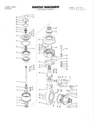
Section 1GeneralIntroductionThis service manual is for the W6F winch. The followinginformation is included in this manual:Section 1. General includes operation descriptionsof systems and components as an aid for troubleshootingand repair.Section 2. Troubleshooting lists common problemsand the possible causes and corrections.Section 3. Service provides a guide for periodicmaintenance, checks and adjustments.Section 4. Repairs describes the removal, disassembly,assembly, and installation of the winch.NOTE: This publication may be translated to differentlanguages for sole purpose of easy reference innon-English speaking locations. Should there bedifferences in interpretations to the text, pleaserefer to the English language edition publishedby <strong>Allied</strong> <strong>Systems</strong> <strong>Company</strong> as the controllingdocument.DescriptionThe W6F Winch is a Power Forward (LINE-IN) and PowerReverse (LINE-OUT) winch used on tractors with a constantrunning power takeoff (PTO). The winch utilizes aSelf Contained Hydraulic (SCH) system where all hydraulicpower is produced internally inside the winch case. Thedesign of the winch case permits different arrangements ofPTO gear assemblies to fit different tractors that use thesewinches. (See Section 4 for the PTO gear assemblies.)The W6F winch has a BRAKE-OFF function, which permitsthe cable to be pulled from the drum. A FREESPOOLfunction is also available.The W6F winch has a rated line pull capacity of 266,880N (60,000 lbf) when there is one layer or less of cable onthe drum. In certain situations, the winch will generatemore line pull and can break the wire rope, rigging orthe winch.DRUM SHAFTRETAINERSERIALNUMBERPLATECLUTCH SHAFTRETAINERBRAKECOVEROILLEVELPLUGsideleftbw.tifDRAWBARFILTER COVERDRAWBAR PININTERMEDIATE SHAFTRETAINER/FREESPOOLDRAG ADJUSTBRAKE SHAFTRETAINERsiderightbw.tifFigure 1-1 Model Views (Winch Shown with Optional Fairlead Installed)1 - 1
GeneralManufactured ByA = <strong>Allied</strong> <strong>Systems</strong> <strong>Company</strong>(no "A" = Hyster <strong>Company</strong>)Winch ModelW6F = StandardK6F = Special Product Engineering DesignDrive TypeP = Power ControlledX = Direct DriveGear Ratio CodeGear Code = Forward Ratio / Reverse Ratio1 = 45.14:1 / 19.47:1 (KOM PS 81.69:1 / 35.24:1)2 = 56.36:1 / 24.31:1 (KOM PS 101.99:1 / 43.99:1)3 = 64.90:1 / 28.10:14 = 81.00:1 / 35.00:15 = 44.00:1 / 19.00:16 = 106.36:1 / 45.88:17 = 27.90:1 / 12.10:18 = 85.19:1 / 36.75:19 = 55.61:1 / 45.88:11 - 2CODE3240414243444546474849ANew Holland/Fiat-Hitachi11B PS11B DD12G14B PS 14 CFL 14B14B 14C DDFD14F/H14C,FD14F/H10C,10C PSFD14E, FD175,DX175,DX195LNew HollandDC-180Unit Identification<strong>Allied</strong> Winch S/N Nameplate Data For Tractor MountingsA W6F P 1 M 1501 C41Figure 1-2 Tractor Identification and Gear RatioTractor Make Model and Starting Tractor Serial Number Where ApplicableCCaterpillar527D5B 24X 25XD5E-PS 95J 96JD5B D53-DD22X 23X 26XD6D PS 3X 4X 5X10X 76A,D6E PSD6D DD 3X 5X74A 99J, D6E DD977, D6G977LEJohn Deere750/750Bw/ CAB750/750Bw/o CAB850/850Bw/ CAB850/850Bw/o Cab855750C,750C Series II850C,850C Series IIHDresserTD15B/C PS,175CTD15BG DD,501250C/ETD15E PSTD15E DDTD 15HKKomatsuVehicle CodeSee Figure 1-2Sequence NumberInternal OptionsM = Horizontal Handlever, Non-Freespool(For Direct Drive Only)F = FreespoolN = Non-Freespool(Vertical Handlever For Direct Drive Only)Notes: 1. In Addition to the serial number plate,the serial number is stamped on to theleft hand side of the frame.2. Circled numbers in Figure 1-2 indicatepossible gear ratios.MMFRJI CaseD60E-6, D60E-8,D60LE-8, D70LE D600C/D 1550D65A/E6D65S-6D75S-3D65-8, D65E-8D68-1D65EX-12D61EX-12LLiebherr732B1850KXXuanhuaT150F
Section 1CODE50717382480481ANew Holland/Fiat-HitachiFigure 1-2 Tractor Identification and Gear Ratio (Continued)Tractor Make Model and Starting Tractor Serial Number Where Applicable (Continued)CCaterpillarD6RD6R Series IID6GD6G2w/o CABD6H/D6R PSD6H DDEJohn DeereHDresserKKomatsuLLiebherrMMFRJI CaseXXuanhua1 - 3
GeneralFigure 1-3 List of Installation DrawingsW6F INSTALLATION DRAWINGS BY TRACTORWinch SerialNumberDescriptionPower ControlInstallationDrawingPart NumberW6FP**A46 W6F FIAT 14C & FD14 286047WW6FP**A47 W6F FIAT 10C 335455WW6FP**A48 W6F F/H FD14E & FD175 1321652WW6FP**A49 W6F NEW HOLLAND DC-180 2304802WW6FP**C40 W6F CAT 527 2302314WW6FP**C43 W6F CAT D6D PS 282143WW6FP**C46 W6F CAT 977L 300643WW6FP**C480 W6F CAT D6 H/R PS 383151WW6FP**C481 W6F CAT D6 H/R PS 383151WW6FP**C49 W6F CAT D6 H/R PS 383171WW6FP**C50 W6F CAT D6R 383151WW6FP**C71 W6F CAT D6R SERIES II 383151WW6FP**C73 W6F CAT D6G 2307251WW6FP**C82 W6F CAT D6G2 2310210W6FP**E41 W6F JD750B 225099WW6FP**E42 W6F JD850B 225099WW6FP**E43 W6F JD850B 225099WW6FP**E44 W6F JD750B 225099WW6FP**E45 W6F JD750C 2301767WW6FP**E46 W6F JD 850C 2301767WW6FP**H41 W6F DRESSER TD15C 268495WW6FP**H44 W6F DRESSER TD15E PS 373649WW6FP**H45 W6F DRESSER TD15E DD 373649WW6FP**H46 W6F DR TD15H PS 373649WW6FP**H47 W6F DRESSER TD15H TIER II, TD15M 373649WW6FP**K45 W6F KOM D65-1/D65-8 347001WW6FP**K46 W6F KOMATSU D65EX-12 2300314WW6FP**K47 W6F KOMATSU D61EX-12 2303690WW6FP**L40 W6F LIEBHERR 732 B 2304895WW6FP**R41 W6F CASE 1550 1310781WW6FP**R49 W6F CASE 1850K 2304802WDirect DriveW6FX**C44 W6FDD, CAT D6D DD 281940WW6FX**K41 W6FDD KOM D60-6 OR -8 226642WW6FX**X41 W6FDD, XUANHUA T150F 2302178WNotes: 1. This list is for operators to keep track of necessary information of their winch installation drawings bytractors.2. If any of the installation drawings listed above is needed, please contact the Service Department of<strong>Allied</strong> <strong>Systems</strong> <strong>Company</strong> at 503-625-2560.1 - 4
Section 1Serial Number CodesThe serial number codes are described on pages 1-2 and1-4 of this manual. The nameplate with the serial numbercode is found on the top left hand side of the winch case.The serial number code is also stamped on the left handside of the winch frame.NameplateThe rated capacity for the winch, as it is equipped, isshown on the nameplate. Each winch is shipped fromthe factory with a nameplate as shown in Figure 1-4. Ifthe nameplate is missing, or the cable does not matchthe information on the nameplate, do not operate thewinch until its capacity is known and a new nameplate isinstalled. Each winch must be operated within its ratedcapacity as shown on the nameplate.Nameplate_2311482B.pdfFigure 1-4 Nameplate1 - 5
GeneralCapacities and SpecificationsRecommended Oil ListRecommended Oils* - Precise Load Positioning Applications(Inching applications such as pipe setting, yo-yo, line sagging, etc.)Ambient Temperature Range Oil Temperature RangeManufacturer Oil Type °F °C °F °CExxonMobil Mobil Fluid 424 (Factory fill) -13 to 122 -25 to 50 -13 to 176 -25 to 80John Deere Hy-Gard -13 to 122 -25 to 50 -13 to 176 -25 to 80Recommended Oils* - General Load Control Applications(Typical applications such as equipment rescue, logging, cable plow, etc.)Ambient Temperature Range Oil Temperature RangeManufacturer Oil Type °F °C °F °CExxonMobil Mobil Fluid 424 (Factory fill) -13 to 122 -25 to 50 -13 to 176 -25 to 80John Deere Hy-Gard -13 to 122 -25 to 50 -13 to 176 -25 to 80Chevron 1000 THF -13 to 122 -25 to 50 -13 to 176 -25 to 80Caterpillar Multipurpose Tractor Oil (MTO) -13 to 104 -25 to 40 -13 to 104 -25 to 40Recommended Oils* - Low Temperature Applications(Note: ExxonMobil and John Deere Oils are recommended for Inching Applications)Ambient Temperature Range Oil Temperature RangeManufacturer Oil Type °F °C °F °CExxonMobil Mobil Fluid LT -40 to 86 -40 to 30 -40 to 150 -40 to 66John Deere Low Viscosity Hy-Gard -40 to 86 -40 to 30 -40 to 150 -40 to 66Chevron THF W -40 to 86 -40 to 30 -40 to 150 -40 to 66* Note: Use of a non-recommended oil may void warranty.Figure 1-5 Recommended Oil ListApproximate Winch Cable CapacitiesCable DiameterCapacity for254 mm (10 in)Drum DiameterCapacity for178 mm (7 in)Drum Diameter19 mm (3/4 in) 113 m (307 ft) 129 m (425 ft)22 mm (7/8 in) 89 m (293 ft) 93 m (305 ft)25 mm (1 in) 63 m (206 ft) 72 m (237 ft)NOTE: Loosely or unevenly spooled line will changecapacities. Use flexible cable with independent wirerope center.Figure 1-6 Drum Line CapacitiesOil CapacityWinch ModelW6FP - StandardW6FP - with DropboxHydraulic SpecificationsFigure 1-7 Oil CapacityOil Capacity16.5 Gal (63L)17 Gal (64.5L)Pump ............................................................. Gear Type10-13 gpm (38-50 l/min) at 1000 rpmOperating pressure ..........................225 psi (1,550 kPa)Valve ..............................................................One SpoolFilters .................................... Full fl ow magnetic strainer20 micron paper cartridge1 - 6
Section 1Winch Torque SpecificationsNOTE: Unless otherwise specified, torqueGrade 5:1/2 UNC to 50 ft-lbs (7 kg-m)3/8 UNC to 25 ft-lbs (4 kg-m)NOTE: All torque values given with threadslubricated.ITEMft-lbsW6Fkg-mPTO Shaft AssemblyBearing Carrier Capscrews 75 10Clutch Shaft AssemblyBearing Retainer CapscrewsBearing Locknut75200Pump Mounting Capscrews 25 4Brake Shaft AssemblyBearing Retainer Capscrews 75 10Intermediate Shaft AssemblyBearing Retainer Capscrews 75 10Freespool Shift Shaft 75 101028Drum Shaft AssemblyRH Bearing Retainer CapscrewsDrum Gear to Adapter CapscrewsDrum Shaft NutsDrum to Adapter CapscrewsClutch AssemblyClutch Piston Housing CapscrewsClutch Piston Housing Setscrews7590400220704010125530106Brake AssemblyCover Nuts 130 18Control ValveMounting Capscrews 50 7Winch Mounting to TractorSee Installation DrawingsFigure 1-8 Torque Specifications1 - 7
GeneralGear Train (See Fig. 1-9 & 1-10)The gear train (Figure 1-9) consists of:1. a PTO shaft assembly2. a clutch shaft assembly3. a brake shaft assembly4. an intermediate shaft assembly; and5. a drum shaft assemblyTorque transfer during operation is shown in Figure 1-10.NOTE: PTO rotation direction is determined by standingbehind tractor and looking forward at the PTOshaft entering the winch case.shaftassy.tifFigure 1-9 Gear Trainbrakeon.tif, linein.tif, lineout.tifBrake On (Neutral) Line In (Forward) Line Out (Reverse)Figure 1-10 Gear Train Rotation Torque Transfer1 - 8
Section 11BRAKEOFFLINEOUTBRAKEONLINEINREAD OPERATINGINSTRUCTIONS 271731WNORMALOPERATIONFREESPOOLFREESPOOLCONTROLBRAKEOFFLINEOUTBRAKEONLINEINREAD OPERATINGINSTRUCTIONS 271731WNORMALOPERATIONFREESPOOLFREESPOOLCONTROL2handlevers2.tif, decal.pdf, adjustable.pdf1. Power Control Lever2. Freespool LeverFigure 1-11 Typical Winch ControlsOperation and Control (See Fig. 1-11)The control lever assembly has a power control lever forwinch control (See Fig 1-11). If the winch does not havethe FREESPOOL function, the second control lever isnot used. Both control levers are connected to the winchthrough control cables. The power control lever is connectedto the spool in the control valve. The power controllever is used to select one of the following operations:BRAKE-OFFLINE-OUTBRAKE-ONLINE-INExcept for the BRAKE-OFF position, a spring arrangementon the spool of the control valve returns the spool andpower control lever to the BRAKE-ON position. A ball anddetent arrangement will hold the spool and control leverin BRAKE-OFF, and the operator must pull the controllever to release it from that position.The BRAKE-OFF position has a detent and is a neutralposition for the clutches. Hydraulic pressure is applied torelease the brake. The winch will not rotate easily becauseof friction in the clutches, brake, and gear train. Cablecannot be pulled from the winch by hand. The BRAKE-OFF position is different from the FREESPOOL positionwhere the drum is disengaged from the gear train. TheBRAKE-OFF position is used when the operator has aload on the winch cable. The operator can move the tractorforward without moving the load.A second control lever disengages and engages a dentalclutch to control the FREESPOOL operation. TheFREESPOOL control lever has two positions: POWERand FREESPOOL. The FREESPOOL control lever disengagesthe gear train so that the cable can be pulledfrom the winch by hand.The BRAKE-ON position is a neutral position. No hydraulicpressure is applied to the brake or the clutches. Springsapply the brake so that the winch drum will not rotate.1 - 9
GeneralFreespool Operation (See Fig. 1-12)The FREESPOOL arrangement allows mechanical disengagementof the drum gear from the remainder of thegear train. When the FREESPOOL handlever is shifted,the dental clutch engages or disengages the drum pinionand intermediate gear.WARNING: When the control lever is movedto the FREESPOOL position it will release thegear train and any load that may be on thecable. An uncontrolled release of the load mayoccur. Loss of the load can result in injuryand damage.The power control lever must be in the BRAKE-ON orBRAKE-OFF positions to operate the FREESPOOL controllever. When the FREESPOOL control lever is moved tothe FREESPOOL position, the sliding sleeve disengagesthe drum pinion gear from the intermediate gear. The geartrain is disengaged from the drum gear so that the cablecan be pulled from the drum by hand. Only the drum anddrum pinion gear rotates when the cable is pulled duringFREESPOOL operation. The resistance to rotation by thedrum during FREESPOOL is controlled by the preload onthe bearings for the intermediate shaft.If the FREESPOOL control lever cannot be moved to engagethe gear train for power operation, apply the clutch tomove the gear train a small amount. This action will alignthe splines in the dental clutch so that the intermediategear can be engaged.freespool.tifFigure 1-12 Freespool1 - 10
Section 1Hydraulic System (See Fig.1-13)The operation of the winch is controlled by an internalhydraulic system. This system directs the fl ow of oil forwinch control functions. The suction and pressure fi ltersremove contaminants from the oil. The hydraulic pumpsupplies pressurized oil for the system. The control valveis connected by a cable to the control lever. The controlvalve distributes and regulates the fl ow and pressure ofhydraulic oil to the clutches and brake while maintainingthe cooling oil flow.A separate accumulator valve, mounted on the front of thecontrol valve body, controls the release of pressurized oilfrom the accumulators. The accumulators provide pressurizedoil for a limited amount of actuation if the hydraulicpump is not functioning. This allows the release of thewinch brake when the tractor engine or the hydraulic pumpis not operating.The operation of the winch is controlled by the clutchesand the brake except when the intermediate shaft is disengagedfor FREESPOOL.When the tractor’s PTO is operating, the hydraulic systemprovides pressure and flow. The hydraulic flow path of thevarious functions is depicted in Fig. 1-20 through Fig. 1-24.hydraulicsys.tifFigure 1-13 Hydraulic System1 - 11
GeneralReverse and Forward Clutches (See Fig. 1-14 and 1-15)The reverse clutch (Fig.1-14) and forward clutch (Fig.1-15) are multi-disc types that are hydraulically appliedand spring released. Oil flow through the clutches is maintainedunder all operating conditions for cooling.revclutch.tifFigure 1-14 Reverse Clutchforwardclutch.tifFigure 1-15 Forward Clutch1 - 12
Section 1Oil Brake Assembly (See Fig. 1-16)The oil brake is a multi-disc brake that is spring applied andhydraulically released. When pressurized oil is directedinto the cavity between the piston and piston housing, thepiston moves outward, compressing the belleville spring,which then releases the brake.brakeassy.tifFigure 1-16 Oil Brake Assembly1 - 13
General6 7 13 8 1011,12AB15,16AB17AB1SECTION B-B6A,Bctrvalve.pdf425149 10 11,12 1315,1631. Valve Body2. Relief Cartridge3. Spool Assembly4. O-Ring5. O-Ring6. Fitting7. Spool8. Housing - Modulator9. Spool10 . Spring11 . Plug12 . O-Ring13 . O-Ring14 . Housing - Modulator15 . Nut16 . Capscrew17 . FittingSECTION A-AFigure 1-17 Hydraulic Control ValveHydraulic Control Valve (See Fig. 1-17)The hydraulic control valve is a single spool valve installedinside the winch frame. The flow of hydraulic oil to and fromthe clutches and brake is controlled by the control valve.Passages inside the valve body connect the oil fl ow andpressure with the functions that control the winch. Thecontrol valve spool opens and closes passages to applyand release the clutches and brake.The control valve spool is connected by a cable to thecontrol lever for operator operation. Built-in pressure modulatorsautomatically ensure positive clutch engagementbefore the brake is fully released. The forward modulatorand reverse modulator are adjustable. The control valvespool is spring loaded in the BRAKE-ON position and hasa detented position to hold it in the BRAKE-OFF position.Hydraulic Control Relief ValveA relief valve is in the control valve to prevent excessive hydraulicoil pressure. Oil from the relief valve is dischargeddirectly to cooling oil passage. Cooling oil is distributedthrough the hydraulic lines to the brake and clutches toremove excess heat.Hydraulic Pump (See Fig. 1-18)The hydraulic pump is a fi xed displacement gear pumpthat supplies the hydaulic fl ow necessary for operation ofthe winch. The pump shaft is driven by a spur gear off ofthe input shaft. The pump inlet port is connected to thewinch suction fi lter. The outlet is connected through thepressure fi lter to the control valve inlet port.1 - 14
Section 1W6F_4-1.pdf1. Front Plate2. Back Plate3. Body4. Drive Gear5. Key6. Idler Gear7. Wear Plate8. O-Ring9. Seal10 . Washer11 . Capscrew12 Gasket13 . Seal14 . Washer15 . Retaining Ring16 . Plug18 . Pump Pinion19. NutAccumulatorsFigure 1-18 Hydraulic PumpAccumulators are connected to the hydraulic system.They have a nitrogen precharge so that the oil stored inthe accumulators will be under pressure. When released,this oil will provide pressure for the hydraulic system duringlow engine rpm shifts or if the PTO shaft stalls. Theyare charged with nitrogen to 100-115 psi.Accumulator Control ValveThe accumulator valve is mounted to the control valveand is actuated by the control valve spool cam. As thehydraulic system builds pressure, oil can fl ow past thecheck ball in the valve to be stored in the accumulators.When the control valve spool is moved to the LINE-IN orLINE-OUT position, a cam on the spool pushes up on theaccumulator valve pin. This pin lifts the check ball off itsseat to release the oil stored in the accumulators. If thePTO should stall so the hydraulic pump does not providesuffi cient fl ow, the stored oil will be released, thus releasingthe brake and applying the clutch.through the hydraulic lines to the brake and clutches toremove excess heat. Oil from the cooling relief valve isdischarged directly into the inside of the winch housing.Turning the center cap clockwise will increase pressure.They have holes drilled into the valve body flats for accessto the cap’s threads. Threads can be upset with a punchwhen correct pressure is obtained, therefore locking thecap into position.Cooling Oil Relief Valve (See Fig. 1-19)The cooling oil relief valve is a spring-loaded, poppet-typevalve. The valve is mounted in the control valve dump portand maintains cooling oil pressure (See Figure 3-8, HydraulicSystem Pressure Tests). Cooling oil is distributedFigure 1-19 Cooling Oil Relief Valvereliefvalve.tif1 - 15
GeneralPRESSURECOOLINGSUCTIONBRAKEOFFLINEOUTBRAKEONNORMALOPERATIONFREESPOOLHANDLEVERPOSITIONLINEINREAD OPERATINGINSTRUCTIONS271731WFREESPOOLCONTROLOILBRAKEREVERSECLUTCHPRESSUREFILTERCHECK VALVECONTROLVALVEHYDRAULICPUMPFORWARDCLUTCHbrakeon_new.pdfSUCTIONSTRAINERACCUMULATORACCUMULATORVALVECOOLINGOIL RELIEFVALVECOOLINGOIL MANIFOLDFigure 1-20 Hydraulic System - BRAKE-ON (Neutral)Sequence of Operation - BRAKE-ONThe control valve spool is spring centered to BRAKE-ON.In this position, oil entering the open center valve flows intothe cooling oil passages. Cooling oil fl ows out of the cool-ing oil manifold to lubricate and cool the brake and clutchassemblies. Excess fl ow goes directly to the sump.1 - 16
Section 1PRESSURECOOLINGSUCTIONBRAKEOFFLINEOUTBRAKEONNORMALOPERATIONFREESPOOLHANDLEVERPOSITIONLINEINREAD OPERATINGINSTRUCTIONS271731WFREESPOOLCONTROLOILBRAKEREVERSECLUTCHPRESSUREFILTERCHECK VALVECONTROLVALVEHYDRAULICPUMPFORWARDCLUTCHlinein_new.pdfSUCTIONSTRAINERACCUMULATORACCUMULATORVALVECOOLINGOIL RELIEFVALVECOOLINGOIL MANIFOLDSequence of Operation - LINE-INFigure 1-21 Hydraulic System - LINE-IN (Forward)For LINE-IN (forward) operation, the operator pulls thelever towards him/herself, which causes the spool to moveinto the valve, closing off the fl ow of oil to the cooling passage.This allows a pressure buildup in the inlet passage.Oil fl ows from the inlet passage to the brake passagethrough an orifi ce, producing a pressure drop betweenthe inlet and brake passage, depending on the amountof oil fl ow. As the brake port to sump is closed off by thespool, the oil fl ow to sump is reduced, allowing the brakepressure to build up. As the brake pressure increases, theforward modulator valve will regulate the oil pressure tothe forward clutch and maintain a constant pressure differentialbetween the brake and clutch through the inchingmode (See Figure 3-8, Hydraulic System Pressure Tests,for factory setting). At the end of the spool travel, a directport to the clutch is opened.NOTE: On a fast shift, the spool moves into the full forwardposition, routing oil directly to the forward clutchand bypassing the forward modulator valve completely,thereby avoiding any delay in operation.When pressure starts to rise above 220±5 psi (1520±35kPa) at the inlet port passage, the spring loaded poppet inthe relief valve will bypass the excess fl ow to the coolingpassage. An orifi ce in the relief valve poppet prevents oilfrom becoming trapped behind the poppet and causinga hydraulic lock.1 - 17
GeneralPRESSURE (220 psi / 1517 kPa)CONTROLLED (10-220 psi / 69-1517 kPa)COOLINGSUCTIONBRAKEOFFLINEOUTBRAKEONNORMALOPERATIONFREESPOOLHANDLEVERPOSITIONLINEINREAD OPERATINGINSTRUCTIONS271731WFREESPOOLCONTROLOILBRAKEREVERSECLUTCHPRESSUREFILTERCHECK VALVECONTROLVALVEHYDRAULICPUMPFORWARDCLUTCHlineoutinching_new.pdfSUCTIONSTRAINERACCUMULATORACCUMULATORVALVECOOLINGOIL RELIEFVALVECOOLINGOIL MANIFOLDSequence of Operation - LINE-OUT INCHINGFigure 1-22 Hydraulic System - LINE-OUT INCHINGLINE-OUT INCHING (gradual brake release) is achievedby slowly pushing the control lever ouf of the brake on(neutral) position towards the line out (reverse) position.As the control spool moves, the fl ow of oil to the coolingpassage is blocked. This allows pressure to build up inthe inlet passage. Oil fl ows from the inlet passage to thebrake passage through an orifi ce, producing a pressuredrop between the inlet and brake passages, depending onthe amount of oil fl ow. As the brake port to sump is closedoff by the spool, the oil fl ow to sump is reduced, allowingthe brake pressure to build up. As the brake pressureincreases, the reverse modulator valve will regulate theoil pressure ot the reverse clutch and maintain a constant120 psi (827 kPa) pressure differential between the brakeand the clutch through the inching mode.1 - 18
Section 1PRESSURECOOLINGSUCTIONBRAKEOFFLINEOUTBRAKEONNORMALOPERATIONFREESPOOLHANDLEVERPOSITIONLINEINREAD OPERATINGINSTRUCTIONS271731WFREESPOOLCONTROLOILBRAKEREVERSECLUTCHPRESSUREFILTERCHECK VALVECONTROLVALVEHYDRAULICPUMPFORWARDCLUTCHlineout_new.pdfSUCTIONSTRAINERACCUMULATORACCUMULATORVALVECOOLINGOIL RELIEFVALVECOOLINGOIL MANIFOLDSequence of Operation - LINE-OUTFigure 1-23 Hydraulic System - LINE-OUT (Reverse)LINE-OUT, or reverse, is achieved by pushing the controllever to the reverse position, thereby pulling the controlspool out. As the control spool moves, the fl ow of oil tothe cooling passage is blocked. This allows pressure tobuild up in the inlet passage. Oil fl ows from the inlet passageto the brake passage through an orifi ce, producinga pressure drop between the inlet and brake passages,depending on the amount of oil fl ow. As the brake portto sump is closed off by the spool, the oil fl ow to sump isreduced, allowing the brake pressure to build up. As thebrake pressure increases, the reverse modulator valvewill regulate the the oil pressure to the reverse clutch andmaintain a constant 120 psi (827 kPa) pressure differentialbetween brake and clutch through inching mode. At theend of spool travel, a direct port to the reverse clutch isopened.NOTE: On a fast shift, the spool moves into the fullreverse position, routing oil directly to the reverseclutch and bypassing the reverse modulator valvecompletely, thereby avoiding any delay in operation.1 - 19
GeneralPRESSURECOOLINGSUCTIONBRAKEOFFLINEOUTBRAKEONNORMALOPERATIONFREESPOOLHANDLEVERPOSITIONLINEINREAD OPERATINGINSTRUCTIONS271731WFREESPOOLCONTROLOILBRAKEREVERSECLUTCHPRESSUREFILTERCHECK VALVECONTROLVALVEHYDRAULICPUMPFORWARDCLUTCHbrakeoff_new.pdfSUCTIONSTRAINERACCUMULATORACCUMULATORVALVECOOLINGOIL RELIEFVALVECOOLINGOIL MANIFOLDSequence of Operation - BRAKE-OFFFigure 1-24 Hydraulic System - BRAKE-OFFBRAKE-OFF is achieved by pushing the control lever tothe BRAKE-OFF position. The lever must be pushed pastLINE-OUT; it will take slightly more force. This position isdetented and the control lever must be moved manuallyto return it to the BRAKE-ON position. With the controlspool in BRAKE-OFF position, oil fl ow to the clutches isblocked and high pressure oil fl ows directly to the brakeport to fully release the brake.1 - 20
Section Notes11 - 21
Notes General1 - 22
®Section 2TroubleshootingGeneralThis section includes several troubleshooting analysischeck charts. The charts list the most common troublesthat may be encountered. A possible cause and recommendedcorrective action are listed to restore the winchto normal operating condition. Figure 2-1 applies to W6Fwinch, and Figure 2-2 applies W6F winch equipped withFREESPOOL.Figure 2-1 Troubleshooting Analysis Check Chart (Continued on next page)PROBLEM POSSIBLE CAUSE CORRECTIONOverheating Plugged pressure filter. Replace filter.Plugged suction filter.Remove suction filter, clean and replace.One or both clutches dragging. Check by placing handlever in BRAKE-OFF. Normallydrum will rotate slowly in the LINE-IN direction.If the reverse clutch is dragging, the drum will rotatein the LINE-OUT direction. If forward clutch is dragging,the drum will rotate positively in the LINE-INdirection and it will take more than 100 lbs. of linepull to prevent drum rotation.Low pressure.Check for leaks, then adjust accordingly.Bevel shaft bearings set too tight. Adjust accordingly.Control cable binding causing winchvalve to not return to BRAKE-ON.Winch control left in BRAKE-OFF.Excessive inching.Make sure that there are no tight bends in the controlcable (minimum bend redii 5.00”), or replace cable.Return lever to BRAKE-ON.Avoid continuous operation in the inching zone.Operation is rough Hydraulic oil is too cold. Put the control lever in the BRAKE-OFF position.Run the engine at 1000 rpm to warm the oil beforeoperating the winch.Low oil level.Add hydraulic oil to the correct level.Low system pressure.See item on troubleshooting low oil pressure directlybelow.Wrong oil.Drain oil and replace with correct grade. Refer tothe Recommended Oil List, Figure 1-4, in Section 1.Accumulator malfunction.Check accumulator and recharge/replace as necessary.Tractor engine idling too low, or PTOstalled.Increase tractor idle speed.Hydraulic system suction leaks.Observe oil exiting lube valve whiletractor is operating. Suction leaks willcause oil to foam.Handlever/Control cables need adjustment.Check the following for air leaks:1. Suction hose to pump connection.2. Pump shaft seal.3. Suction filter cover and gasket.4. Suction hose for cracks or collapsed sections.Check for correct adjustment as outlined in Section3. Make sure the ends of the cables are fastenedcorrectly. Double-check push-pull cable housing toensure it is securely anchored on both ends. Besure control lever has full movement and is not hittinghousing.2 - 1
Troubleshooting®Figure 2-1 Troubleshooting Analysis Check Chart (continued)PROBLEM POSSIBLE CAUSE CORRECTIONLow oil pressureBrake does not releaseor winch stalls during lowRPM shiftLeaking pressure hoses and fittings.Defective or improperly adjusted oilrelief valve; poppet may be stuckopen.Clogged suction filter.Oil brake leaking internally (indicatedby low brake pressure).Defective hydraulic pump.Valve spool is not moving farenoughLow oil pressure.Pressure modulator set too low.Accumulator system malfunction.Damaged brake piston, piston housingor seal rings.Low clutch pressure or low oil pumpvolume.Check for leaks and replace components wherenecessary. Be sure hoses are not rubbing on anygears or winch components.Clean relief valve if no pressure, then adjust. Checkrelief valve with pressure gauge. Replace if defective.Check and clean or replace suction filter.Repair as required.Check pump pressure output only after all otherchecks have been made. Worn pump indicated bypressure variation with engine RPM. If pump is atfault, replace.Check to verify the control valve spool travel (referto Control Valve Spool Travel Check on pages 3-7and 3-8).Refer to “Low Oil Pressure” troubleshooting itemabove.Turn modulator screw IN for earlier brake release.Increase sequence differential.Check for:1. Correct leakdown time as described in Section3.2. Leaking accumulator valve.3. Leak in accumulator lines.4. Damaged or defective accumulators.Check piston and piston housing cavity for damage.Replace if scored or broken. Always replace bothseals when brake is repaired.Refer to “Low Forward or Reverse Clutch Pressure”troubleshooting item below.Oil brake slipping or drumbackspin on fast shiftfrom neutral to forwardBrake releases beforeforward clutch engagementBrake releases beforereverse clutch engagementWorn brake plates.Check the required pressure to release the brake.Replace friction discs and separator plates if pressureis too low.Broken belleville spring. Replace. Refer to Section 4.Modulator valve in control valve not Check forward modulator valve.functioning.Low brake release pressure (sameas the above).Modulator valve in control valve notfunctioning.See “Oil Brake Slipping” troubleshooting itemabove.Check forward modulator valve. Adjust or replaceas necessary.2 - 2
®Section 2Figure 2-1 Troubleshooting Analysis Check Chart (continued)PROBLEM POSSIBLE CAUSE CORRECTIONLow forward or reverseclutchWinch will not operatewhile tracks are turningForward or reverse oilclutch not engagingForward or reverse oilclutch not releasingForward clutch engagingor releasing slowlyBroken seal rings on the bevel gearshaft.Damaged bevel gear shaft seal ringgrooves.Damaged bevel gear shaft bearingretainers.Damaged clutch piston, piston retaineror O-rings.Reverse pressure hose damaged bybevel gear.Leaky clutch circuit.Leak in hydraulic system, or loosehydraulic connections.Accumulator system malfunction.Low oil pressure.Defective PTO shaft.Low oil pressure.Low forward or reverse clutch pressure.Inadequate piston travel.Worn friction discs and separatorplates.Broken or weak release springs.Warped frictions or separators.Lube pressure high.Improper orientation of forwardclutch and clutch shaft.Replace seal rings.NOTE: A broken seal ring is the most common causeof a pressure differential between the two clutches.Check preload on clutch/brake shaft and adjust it ifnecessary to prevent additional breakage of sealrings; refer to Section 4.Check grooves for taper, scoring and rust. Replaceor rebuild shaft if surfaces between the inner side ofgroove and seal ring are not flat.Check retainer for grooves. Replace retainer if defective,or re-sleeve.Check piston and piston retainer cavity for damage.Always repair both O-rings when clutch is repaired.Refer to Section 4.Remove cover and inspect.Perform clutch bleed-down test on clutch circuit.Visually inspect winch for leaks, and ensure hydraulicconnections are secure.Check for:1. Correct leakdown time as described in Section 3.2. Leaking accumulator valve.3. Leak in accumulator lines.4. Damaged or defective accumulators.Refer to “Low Oil Pressure” troubleshooting itemabove.Inspect PTO shaft and coupling, clutch shaft bevelring gear and PTO shaft pinion gear for wear or damage.Inspect magnetic suction screen.See “Low Oil Pressure” troubleshooting item above.See troubleshooting for “Low Forward or ReverseClutch Pressure” item above.Remove the access cover and place the winch ingear while visually checking the clutch for pistonmovement.Replace the friction discs and separator plates if toothin, scored or distorted. Refer to Section 4.Check springs and replace as necessary.Replace as necessary.Test and re-set cooling oil relief valve.Remove and reinstall shaft with proper alignment.Refer to Section 4.2 - 3
Troubleshooting®Figure 2-2 Troubleshooting Analysis Check Chart for FREESPOOL OptionPROBLEM POSSIBLE CAUSE CORRECTIONHard to shift Linkage binding or rusted. Repair.Jumps out of gearShifting collar too tight on splines orsplines rough.Dental clutch installed backwards.Ball detent spring load too much.Control linkage improperly adjusted.Worn shifter fork.Remove shifting collar, dress splines with fine stone,and replace parts if necessary.Install clutch so that chamfered ramp faces drumpinion gear.Back off on spring plug.Check and adjust as necessary.Replace shifter fork and related parts as necessary.Replace bushing and related parts as necessary.Clean or replace as necessary.Worn drum pinion gear bushing.Detent ball and spring loose, damagedor sticking.Winch will not freespool Linkage improperly adjusted. Check and adjust as necessary.Intermediate shaft assembly damaged,Adjust or repair as necessary. Refer to Section 4.rusted orpreloaded.Winch freespools tooeasilyDrum shaft assembly damaged,rusted or binding.Insufficient preload on intermediateshaft.Adjust or repair as necessary.On winches with exterior Freespool Drag Adjust:Tighten preload on the intermediate shaft.Winch freespools toohardToo much preload on intermediateshaft.On winches without exterior Freespool Drag Adjust:Remove shims as required to preload shaft. Referto Section 4.On winches with exterior Freespool Drag Adjust:Loosen preload on the intermediate shaft.On winches without exterior Freespool Drag Adjust:Add shims as required to preload shaft. Refer toSection 4.NOTE: It may be necessary to use a slide hammeron the shaft to unload the bearing race becauseof the fit in the bore.2 - 4
®Section Notes22 - 5
Notes Troubleshooting®2 - 6
Section 3ServiceGeneralThis section provides the instructions for performing maintenanceand making checks and adjustments. Standardshop tools are used in doing the work described in this section,except where noted (See Figures 4-23 and 4-24).MaintenanceThe Maintenance Schedule is a program that includesperiodic inspection and lubrication. Use the operatingtime on the hour meter of the tractor to determine themaintenance time for the winch.1. Access Cover for Control Valve2. Plug to Check Oil Level3. Plug to Drain Oil4. Cover for Filter5. Fill Plug6. BreatherW6F MaintenancePoints.pdfFigure 3-1 W6F Maintenance PointsINTERVAL PROCEDURE OR QUANTITY SPECIFICATION50 hours or weekly Check oil level at plug (item 2). Add oil as necessarythrough fill plug (item 5). Do not operate tractor whenchecking the oil level.Check winch control lever, and the FREESPOOL controllever. See Figures 3-3 and 3-4.Clean the breather (item 6).Lubricate the rollers on the fairlead assembly, if thewinch is so equipped.500 hours or every 3 Clean the oil suction screen and magnets.*monthsClean the breather.Replace the fi lter.*1000 hours or every 6monthsChange the hydraulic oil. Drain oil from plug (item 3).Clean the oil strainer. Through fi ll plug (item 5), add14.5 gallons (55 liters) † . Check the oil level at item 2.Figure 3-2 Maintenance ScheduleSee Figure 1-4, the Recommended Oil List,in Section 1.Use SAE 30 oil on the linkage as needed.Check that the control cable and control housingare fastened correctly. Tighten U-bolts ifrequired.Remove debris around breather.Use multi-purpose grease with 2-4% molybdenumdisulfi de.Use a new gasket between the cover and thesuction tube.Remove debris around the breather.See the Parts Manual for fi lter element andcover gasket. When replacing, be sure tolubricate fi lter seal ring between element andfi lter head.See Figure 1-4, the Recommended Oil List,in Section 1.* NOTE: Clean the oil strainer screen and change the oil fi lter after the fi rst 250 hours on new and rebuilt winches.†Amount of oil may vary slightly with tractor.3 - 1
Service1. Freespool Control Lever2. Power Control Lever3. Freespool Control Cable4. U-Bolt5. Power Control Cable6. Lock Nutleverconfi g1.pcxleverconfi g4.tifFigure 3-3 Control Cable AdjustmentsChecks Before OperationCheck that the cable and hook are not worn or damaged.Check that the periodic inspection and maintenance hasbeen done at the recommended operating hours. SeeFigure 3-2, Maintenance Schedule.Checks During OperationThe Troubleshooting Chart in Section 2 can be used bythe operator to identify a problem with the winch operation.A trained service person is needed for additionaltroubleshooting and repair that requires disassembly ofparts of the winch.Checks and AdjustmentsThe checks and adjustments for the cable controls winchare as follows:• Control Cable Adjustments• Freespool Cable AdjustmentControl Cable AdjustmentsA single control cable connects the power lever to thehydraulic control valve spool. Check the operation of thepower control lever to make sure it moves smoothly andwill return to the BRAKE-ON position. The power controllever will stay in BRAKE-OFF when pushed into DETENT-ED position. Cable adjustment is not necessary except toensure full spool travel. To adjust handlevers depicted inFigures 3-3 through 3-4, proceed as follows:1. Power Control Lever2. Freespool Control Lever3. Housing4. Locknut6. U-Bolt7. Freespool Control Cable8. Power Control Cable9. Spacer10. Pivot PinFigure 3-4 Control Cable Adjustments (this configurationlast used in 1993)1. Ensure that the cable bracket at winch end of controlcable is securely attached to the winch housing.2. Check the position of the handlever with control valvein BRAKE-ON. The lever should be approximatelyvertical. If not, loosen nuts on U-Bolt that clamps thecontrol cable to the handlever housing. Move U-Boltup or down the elongated slots to improve positionof handlever. Tighten nuts securely.3. Move handlever to LINE-IN and BRAKE-OFF positionsand ensure that the lever holds in the BRAKE-OFF position. Check to ensure that the handleverdoes not hit the housing in either position. If interferenceis found, repeat step 2.To adjust the handlever depicted in Figure 3-5, proceedas follows:1. Make sure the positions of the power control lever arethe same as the position indicators on the decal.2. Remove the access cover (Item 1) on the housing tomake adjustments.3. Loosen the jam nut (Item 8) that keeps the tall nut(Item 3) from turning.3 - 2
Section 3The addition or removal of shims for the preload on thebearings of the intermediate shaft requires the removalof the cover for the intermediate shaft. This adjustment isnormally only necessary if the winch has had an overhaul.See Section 4 if this adjustment is required.leverconfi g2.pdf1. Access Cover2. Clevis3. Tall Nut4. Cotter Pin and Link Pin5. Control Cable6. Control Lever8. Jam Nut9. Button Head CapscrewFigure 3-5 Control Cable Adjustments4. Remove the cotter pin and link pin (Item 4) from theclevis (Item 2). Turn the tall nut and clevis to adjustthe length of the control cable (Item 5).FREESPOOL Drag Adjustment for AW6F-4062 andafter, with Exterior Drag Adjust (See Figure 3-5)The preload on the bearings of the intermediate shaftcontrols the resistance to rotation of the drum during theFREESPOOL operation. The resistance to rotation is correctwhen the drum can be rotated by hand, but the drumwill not rotate more than one-half revolution freely.On W6F winches S/N 4062 and above, an adjustingscrew is located in the center of the bearing retainer forthe intermediate shaft; please refer to Figure 3-6. Thisscrew can be tightened or loosened to adjust the preloadon the intermediate shaft. The jam nut will maintain theFREESPOOL setting.5. Use the link pin and cotter pin to connect the clevis tothe control handle again and check the operation.6. When the adjustment is complete, tighten the jam nutand install the access cover.FREESPOOL Cable AdjustmentThe only adjustment necessary is to position the handleverso that it allows the linkage to shift the FREESPOOLmechanism to normal and FREESPOOL positions. Checkthe operation of the FREESPOOL lever for smooth operation.Each of the two positions has a detent.Check that the positions of the FREESPOOL lever are thesame as the position indicators on the control housing.Loosen the U-bolt that holds the control cable in the housingto adjust the control lever. Make sure the control leverdoes not hit the housing at the end of its travel. The linkageand cable must be adjusted so that the FREESPOOLshifter mechanism will slide the drum pinion gear to bothdetent positions.FREESPOOL Drag Adjustment for AW6F-4061 andprior, without Exterior Drag AdjustThe preload on the bearings of the intermediate shaftcontrols the resistance to rotation of the drum during theFREESPOOL operation. The resistance to rotation is correctwhen the drum can be rotated by hand, but the drumwill not rotate more than one-half revolution freely.freespooladjust.pdf1. Adjusting Screw2. Jam NutFigure 3-6 FREESPOOL AdjustmentsSetting the preload on the intermediate shafttoo tight will cause bearing overload. Settingthe preload too loose will allow shaft to notbe parallel. Use caution when adjusting. Determinethe correct preload by starting with thepreload too loose, and gradually increase thepreload until the correct resistance to rotationis achieved (see Page 16). Increase the preloadby turning the adjusting screw by a maximumof 1/6 rotation (60 degrees), and striking thehousing with a mallet to make sure the bearingis sliding. Check resistance to rotation aftereach adjustment.3 - 3
ServiceHydraulic System Pressure Checks (Fig.3-7)The hydraulic oil and fi lter(s) should be maintained asindicated in the Maintenance Schedule. If any problemsare found, they should be corrected before operating thewinch.PreparationPrior to checking the hydraulic pressures, perform thefollowing:1. Check oil level.2. Remove cable from drum to prevent engtanglementduring pressure checks since the drum will rotateduring the tests.Vehicle engine must be shut OFF before disconnectingdrum wire rope. Be careful whenyou remove the wire rope from the drum. Theend of the wire rope can move like a compressedspring, possibly causing an injurywhen the ferrule is released from the drum.Always wear gloves when handling wire rope.3. Start the engine and place the winch in BRAKE-OFFto raise the oil temperature to at least 20°C (70°F).4. Remove any dirt from the left side of the winch. Removecontrol valve access plate.5. Stabilize engine speed at 1000 RPM for all testsunless otherwise specified.6. Conduct tests in order outlined below.7. When complete, install control valve access coverand gasket, and tighten capscrews. (Capscrews musthave sealant and locking patch.)Pressure gaugesTwo 400 psi (28 kg/cm²) and one 30 psi (2 kg/cm²) calibratedpressure test gauges are required to perform thehydraulic pressure checks.NOTE: Shut off the tractor engine when connectingand disconnecting test gauges.Place handlever in BRAKE-ON to prevent accidentaldischarge of pressurized oil storedin the accumulators.Brake Pressure CheckWith the engine shut off, connect one high pressure gaugeto Brake Port D with a ¼" JIC (37° fl are) female adapter.Start the engine and refer to Figure 3-8. Adequate brakepressure is required to fully release the brake. If the pressureis not as specifi ed, check for:1. Improper relief valve setting or malfunction2. Suction or pressure fi lter malfunction3. Leaking pressure hoses or fi ttings4. A defective hydraulic pump. A defective pump isusually indicated by low pressure and pressureincreases with increased engine RPMs.Cooling Oil Pressure CheckWith the engine shut off, connect one low pressure gaugeto Port C. Start the engine and see the Cooling sectionin Figure 3-8. If the cooling oil pressure is too high, it canstroke the clutch piston and drag the clutch pack. Theresult is overheating. Low cooling oil pressure will notproduce enough cooling oil fl ow and cause overheating.Check for a defective cooling oil relief valve.Adjust relief valve as follows:1. Start engine and place handlever in BRAKE-OFF.2. Loosen relief valve locknut. Turn relief valve adjustingcapscrew IN to increase pressure and OUT todecrease pressure. Adjust pressures as shown inFigure 3-8.3. Tighten locknut after adjustment is completed.4. Recheck pressure reading and repeat steps 2 and3 if necessary.Accumulator Pressure CheckWith the engine shut off, connect one low pressure gaugeto Port D. This check determines if the accumulators arefunctioning and have the correct nitrogen charge. Observethe following while referring to the accumulator section inFigure 3-8.3 - 4
Section 3W SERIES PRESSURE DIAGRAM240220RELIEF PRESSURE INLET AINLETA240220200200180180PRESSURE (PSI)1601401201008060BRAKEDBRAKEDBFORWARD CLUTCH1601401201008060REVERSE CLUTCH4020C4020pressurechart.pdf0.75 0.7 0.6 0.5 0.4 0.3 0.2 0.1 0 0.1 0.2 0.3BC50 PSI MODULATOR SETTING100 PSI MODULATOR SETTINGSPOOL TRAVEL (INCHES)BRAKE-OFF REVERSE INCHING BRAKEONINCHINGFORWARDpresscheck.tifFigure 3-7 Hydraulic System Pressure Checks3 - 5
ServiceITEMFUNCTIONCHECKPORTFigure 3-8 Hydraulic System Pressure TestsTEST EQUIP-MENT REQUIREDBrake D – Brake 1 – 400 psi(25 kg/cm 2 ) gaugeCONTROLPOSITIONPRESSUREBRAKE-OFF 220 psi (15.5 kg/cm 2 )Pressure not to exceed250 psi at highidleCooling C – Cooling 1 – 30 psi gauge BRAKE-ON 8-11 psi at full throttle(0.57-0.61 kg/cm 2 )CORRECTIVEACTIONAdjust relief valveCheck or replace coolingoil relief valveAccumulator D – Brake 1 – 400 psi(25 kg/cm 2 ) gaugeLINE-IN (Forward)LINE-IN(Inching)LINE-OUT(Reverse)LINE-OUT(Inching)B – ForwardB – ForwardD – BrakeC – ReverseC – ReverseD – Brake1 – 400 psi(25 kg/cm 2 ) gauge2 – 400 psi(25 kg/cm 2 ) gauge1 – 400 psi(25 kg/cm 2 ) gauge2 – 400 psi(25 kg/cm 2 ) gauge1. BRAKE-OFF2. BRAKE-ON3. Stop Engine4. BRAKE-OFF5. Repeat if required220 psi (15.5 kg/cm 2 )NoneNone—wait 1 minute175 psi (12.8 kg/cm 2 )minimum immediately& 100 psi (7 kg/cm 2 )minimum after 30 seconds1. Check hydrauliclines for leaks2. Replace accumulatorvalve3. Check for defectiveaccumulatorsLINE-IN 220 psi (15.5 kg/cm 2 ) Refer to Section 2,Figure 2-1 for LowForward or ReverseClutch Pressure troubleshootingproceduresVary betweenBRAKE-ON andLINE-INPort B 50 psi (3.5 kg/cm 2 ) less than PortD* (Deere 750/755 &Komatsu use 90 psi[6.3 kg/cm 2 ])Check or replace forwardmodulator valveLINE-OUT 220 psi (15.5 kg/cm 2 ) Refer to Section 2,Figure 2-1 for LowForward or ReverseClutch Pressure troubleshootingproceduresVary betweenBRAKE-ON andLINE-OUTPort C 120 psi(8.4 kg/cm 2 ) less thanPort DAdjust reverse modulator* The pressures specifi ed are based on winches equipped with paper-type friction materials in the brake and clutches.The W6F models used metal friction materials in early models, which require different modulator pressure adjustmentsas follows:3 - 6FRICTION MATERIAL TYPEPRESURE DIFFERENTIAL BETWEENBRAKE & CLUTCHSERIAL NUMBERSEQUENCE BREAKSClutch Brake LINE-IN INCHING LINE-OUT INCHING W6FMetal Metal 20 psi (1.4 kg/cm 2 ) 80 psi (5.6 kg/cm 2 ) Prior to 1689Metal Paper 20 psi (1.4 kg/cm 2 ) 100 psi (7.0 kg/cm 2 ) 1689 - 1999Paper Paper 50 psi (3.5 kg/cm 2 ) 120 psi (8.4 kg/cm 2 ) 2000 - upPressure readings may vary +/- 5 psi (0.4 kg/cm 2 ).NOTE: All John Deere Mountings use paper frictions in clutches and brake regardless of serial number.
Section 31. With engine running, place handlever in BRAKE-OFF and rev engine to maintain 220 psi (1520 kPa)for one minute. This will ensure that the accumulatorswill have a full supply of oil.2. Return handlever to BRAKE-ON.3. Shut the engine off and wait one minute.4. Place the handlever in the BRAKE-OFF position.This will release the oil in the accumulators. Observethe initial pressure reading and the time for the pressureto drop below that specifi ed in Figure 3-8.If the leak down time is less than specifi ed in Figure 3-8,repeat steps 1 through 4, but do not delay in placing thehandlever in BRAKE-OFF after the engine is shut down.If the leak down time is greater than that measured whenwaiting one minute, then there is either a leak in the linesbetween the accumulators and the accumulator valve ora leaking accumulator check valve. Low accumulator gaspressures will tend to stall the winch on a low engine rpmshift. To determine if accumulators have any gas pressure,remove valve stem protective cover and push gently onvalve stem. A ruptured bladder will emit oil. Accumulatorsare not rebuildable.Forward Clutch Pressure Check and Forward ModulatorValve CheckWith the engine shut off, connect one low pressuregauge to Port B. Start the engine and place handleverin BRAKE-OFF to build up the accumulator systempressure. Place handlever in LINE-IN position and checkFORWARD (LINE-IN) clutch and LINE-IN INCHINGpressures as indicated in Figure 3-8. On a fast shift theclutch pressure should come up with the brake pressure.In LINE-IN INCHING the clutch pressure should lag thebrake release pressure as shown in Figure 3-8. If the pressuredifferential is too low the brake will not release soonenough and cause it to stall. If the pressure differentialis too high the brake will release too soon and causebackspinning of the drum.If the forward clutch pressure is not as specifi ed in Figure3-8, check for:1. Leaking pressure hoses or fi ttings2. Damaged or worn clutch piston seals3. Improper control valve spool movement4. Broken seal rings on clutch shaft5. Damaged O-rings on clutch shaft. Troubleshootinginformation is given in Section 2.If the LINE-IN INCHING pressure differential is not asspecifi ed in Figure 3-8, remove the forward modulatorvalve and check for defective or dirty parts. To adjust themodulator valve, proceed as follows:1. Loosen the forward modulator adjustment locknut.With engine running move the handlever towardLlNE-IN until the brake pressure reads 140 PSI (9.5kg/cm² ). Use 180 PSI (12.7 kg/cm² ) for KomatsuD65.2. Turn the adjusting capscrew IN to decrease ForwardClutch Pressure, or OUT to increase pressure untilthe Forward Clutch Pressure is less than the brakepressure by the amount specifi ed in Figure 3-8.3. Tighten locknut and recheck pressure. Repeat steps1 and 2 if necessary.Reverse Clutch Pressure Check and Reverse ModulatorValve AdjustmentShut off the engine and connect the high pressure gaugeto Reverse Clutch Port C. Start the engine. Place the handleverin LINE-OUT and check reverse clutch and LINE-OUT INCHING pressures as indicated in Figure 3-8. Ona fast LINE-OUT shift the clutch pressure should comeup with the brake pressure. In LINE-OUT INCHING theclutch pressure should lag the brake release pressure asshown in Figure 3-8. If the pressure differential is too lowthe brake will not release soon enough and cause drag. Ifthe pressure differential is too high the brake will releasetoo soon and cause backspinning of the drum.If the reverse clutch pressure is not as specifi ed in Figure3-8, check for:1. Leaking pressure hoses or fi ttings2. Damaged or worn clutch piston seals3. Improper control valve spool movement4. Broken seal rings on clutch shaft5. Damaged O-rings on clutch shaft. Troubleshootinginformation is given in Section 2.If the LINE-OUT INCHING pressure differential is not asspecified in Figure 3-9, proceed as follows:3 - 7
Service1. Loosen the reverse modulator adjustment locknutand start engine. Move the handlever towards LINE-OUT until the brake pressure reads 140 PSI (9.8 kg/cm²). Use 180 PSI for Komatsu D65.2. Turn the adjusting capscrew IN to decrease ReverseClutch Pressure, or OUT to increase pressure untilReverse Clutch Pressure is less than the brake pressureby the amount shown in Figure 3-8.NOTE: The spool is detented in BRAKE-OFF. If spooldoes not hold in this position, examine the detentparts inside the spool end cap and repair or replaceas necessary.DETERMINE THISPOSITION (BRAKE ON)FIRST AS A REFERENCEPOINT3. Tighten locknut and recheck pressure. Repeat steps1 and 2 if necessary.Control Valve Spool Travel Check (See Fig. 3-9)It may be necessary to check spool travel when controlvalve pressures do not meet specifi cations. Figure 3-7shows the correct travel for the various spool positions.The control valve spool is self-positioned to BRAKE-ON.The three other travel positions are determined by spoolassembly internal stops and a detent assembly in thespool end cap. If spool travel is found to be out of adjustment,the spool assembly or complete control valve assemblyshould be replaced. Ensure that the spool end capis installed securely, then perform the check for smoothreturn of handlever to neutral from any other position. Anybinding or sticking should be investigated by removing thespool cap and examining parts for wear.spooltrv.pdf.750"(19mm) .500"(13mm).312"(8mm)LINE INBRAKE ONLINE OUTBRAKE OFFFigure 3-9 Control Valve Spool Travel3 - 8
Section 3Decal, Nameplate and Service Plate InstallationThe unit nameplate, a Warning Decal and a MaintenanceInstructions Decal are located on the winch. If the nameplatehas been damaged, obtain a new one and install thenew nameplate in the location shown in Figure 3-10. If theWarning Decal or Maintenance Instructions Decal havebeen damaged, install a new one in the location shown.The model decals are used on both sides of the winchframe as shown. Replace as necessary.Nameplate_Decal.pdfFigure 3-10 Decal Installation3 - 9
Notes Service3 - 10
Section 4RepairsGeneralThis section includes the removal and disassembly of allmajor shaft assemblies, inspection of components, andreassembly and installation. The wear points detailed inFigure 4-13 should be inspected at the time of disassemblyso that worn parts may be ordered and replaced prior toreassembly. If the winch is to be completely overhauled,perform the removal, disassembly, inspection and reassemblyprocedures in the sequence of the followingparagraphs.NOTE: Always use the troubleshooting proceduresgiven in Section 2 to locate a malfunction before performinga major overhaul of the unit. Make all checksin a systematic manner. Haphazard checking wastestime and can cause further damage.Review and perform any adjustments that may be thecause of a malfunction (refer to Section 3).Use new seals, gaskets and O-rings when installingcomponents.Cleanliness is of extreme importance in therepair and overhaul of any hydraulic unit. Beforeattempting any repairs, the exterior of thewinch must be thoroughly cleaned to preventthe possibility of contamination.Winch Removal1. Remove the arch or fairlead from the winch. If theseaccessories are left on the winch, the winch may notremain level when lifted from the tractor.2. Remove the cable from the drum. Clean the outsideof the winch and the area where the winch contactsthe tractor.3. Move the control lever to the LINE-IN or LINE-OUTposition at least three times to discharge the pressurein the accumulator.4. Disconnect control cable and freespool cable fromwinch.5. Connect slings and a crane or lifting device to thewinch. Install lifting eyes (refer to Fig. 4-25 on page62) into the lifting holes provided in the frame.The slings and crane used to lift the winchmust have a minimum lifting capacity of 1500kg (3000 lb.).6. Remove transmission cover, if necessary, to removecenter mounting nuts.7. Remove mounting nuts or capscrews securing winchto tractor with the following steps:a. Remove all but two top outer nuts;b. Loosen the two top outer nuts to end of studs;c. Pry winch loose;d. Remove the two top outer nuts;e. Remove winch.Winch DisassemblyMost repairs require disassembly of the winch, althoughmany major assemblies can be removed from the winchwith the winch still on the tractor. The procedures in thissection describe a complete unit overhaul with the winchremoved from the tractor. However, winch removal is notnecessary for removal of individual shaft assemblies.Disassemble the winch as necessary to make repairs.Figures 4-1 and 4-2 show the gears and componentscontained within the winch housing.Be careful when you remove the wire ropefrom the drum. The end of the wire rope canmove like a compressed spring, causing aninjury when the ferrule is released from thedrum.4 - 1
Repairs - PTO Disassemblygenarr.pdf4 - 2Figure 4-1 General Arrangement, Non-Freespool
Section 4A = 78°genarrfs.pdfPTO Shaft Removal and DisassemblyFigure 4 -2 Freespool ArrangementPlease refer to Fig. 4-3 through Fig. 4-6. Before removingthe PTO shaft assembly, the winch must be removed fromthe tractor as explained above in Winch Removal.1. Remove sealing capscrews. If winch is equipped witha drive adapter, refer to Step 4.2. Pull PTO shaft assembly straight out.Tag the shim pack so that the exact numberof shims are re-installed.3. Disassemble and inspect PTO shaft (refer to Fig. 4-3through Fig. 4-6).4. If equipped with a drive adapter, remove the driveadapter box fi rst (refer to Fig. 4-7 through Fig. 4-10),then the bevel pinion gear and carrier. Disassembleand inspect as required.oldptos.tif1 Snap Ring2 Bevel Pinion Gear3 Bearing Carrier4 O-Ring5 Drilled Head Capscrew6 Oil Seal7 Coupling8 Pin9 Shaft10 Ball Bearing11 Snap Ring12 Shaft & Integral Pinion Gear13 Locknut14 Seal Spacer15 Lockring16 Shim PackFigure 4-3 PTO Shafts - Last Used on W6FP-3699, W6FX-3699 & AW6F-10004 - 3
Repairs - PTO Disassembly12415567817324117814ptoshaft1.pdf3PTO Shaft WithRemovable BevelPinion Gear12131110910PTO Shaft WithIntegral BevelPinion Gear16113159ptoshaft2.pdf1. Snap Ring2. Ball Bearing3. Bearing Carrier4. Capscrew5. Lockring6. O-Ring7. Pin8. Coupling9. Lockring10. Spacer11. Oil Seal12. O-Ring13. Shim Pack14. PTO Shaft15. LockwireFigure 4-4 PTO Shafts, First Used on AW6F-1001Used on Gear Ratios 6,8 & 9 Only123945761314213Used on Gear Ratios 1& 2 Only1112pto-cat527int.epspto-cat527rem.pdf8114101091. Ball Bearing2. Snap Ring, Interior3. Bearing Carrier4. Oil Seal5. O-Ring6. Coupling7. Pin8. PTO Shaft with Integral Bevel Pinion Gear9. Capscrew10. Lockwire11. O-Ring12. PTO Shaft13. Gear14. Snap Ring, ExteriorFigure 4-5 PTO Shaft on W6F for Caterpillar 5274 - 4
Section 4oldjdpto1.tif1. Snap Ring2. Bevel Pinion Gear3. Bearing Carrier4. O-Ring5. Capscrew & Washer6. Oil Seal7. Ball Bearings8. Shim Pack9. Shaft10. Shaft with Integral Pinion11. Washer12. Yoke13. Nut14. Snap Ringoldjdpto2.tifJohn Deere 755 (E32)John Deere 750 (E32)- Last Used on W6F-7143 & AW6F-1000John Deere 855 (E42)John Deere 850 (E42)- Last Used on W6F-7143 & AW6F-10001. Bearing Carrier2. Bearing Cup3. Bearing Cone4. Bearing Cup5. Bearing Cone6. Seal7. Shim Pack12. Washer14. Capscrew15. Thrust Washer17. Spacer18. Spacer19. Yoke20. Shaft21. PTO Shaft22. Gear23. Capscrew24 . Washer373008c_Reassy.pdf15187175Sealant1922232132145Sealant6 24162303691A.pdf12201420321John Deere 750 (E32, E41) / 850 (E42, E43)- First Used on S/N W6F-7144 & AW6F-1001John Deere 750A (E32, E41) / 850A (E42, E43)John Deere 750B (E32, E41) / 850B (E42, E43)- First Used on S/N W6F-7144 & AW6F-1001,Gear Ratios 3, 4, 6, 8 & 9 OnlyJohn Deere 750C (E45) / 850C (E46),Gear Ratios 6, 8 & 9 Only4612187John Deere 750B (E32, E41) / 850B (E42, E43)& 750C (E45) / 850C (E46),Gear Ratios 1 & 2 Only17Figure 4-18 W6F John Deere PTO Shafts4 - 5
Repairs- PTO Disassembly983474 62 3 510 11 12 13 141516171819202122,2324125kom-d65drop.pdf3332313029282726oldkomdropbox.tif1. Pinion Shaft2. Locknut3. Bevel Pinion Gear4. Bearing Carrier5. O-Ring6. Shaft7. Ball Bearing8. Gear Housing9. Bearing Cone10. Pinion11. Bearing Cup12. O-Ring13. Shim Pack14. Carrier15. Oil Seal16. Yoke17. O-Ring18. Nut19. Washer20. Snap Ring21. Carrier22. Capscrew23. Keeper24. O-Ring25. Snap Ring26. Snap Ring27. Housing28. Plug29. Gear30. O-Ring31. Bearing Cup32. Bearing Cone33. Lockwasher34. Gear1. Locknut2. Bevel Pinion Gear3. Bearing Carrier4. O-Ring5. Capscrew6. Gear7. Snap Ring8. Shaft9. Housing10. Bearing Cup11. Bearing Cone12. Gear13. Bearing Cup14. Bearing Cone15. Carrier16. Oil Seal17. Yoke18. Slotted Nut19. Cotter Pin20. Washer21. Shaft22. Capscrew23. O-Ring24. Bearing Cup25. Bearing Cone26. Shim pack27. Lockwasher28. Shim pack29. Snap RingFigure 4-7 Gearbox on W6F for Komatsu D61EX-12 (K47) &D65EX-12 (K46)Figure 4-9 Gearbox on W6F for Komatsu D65E-6,D65E-7, D65E-8 (K41) & D68E-1 (K45)253861092520214017,182211674213,1441PTO(REF.)383164g.pdf1. Drop Box2. Top Gear3. Idler Gear5. Ball Bearing6. Ball Bearing7. Inner Race8. Snap Ring9. O-Ring10. Pin13. Bearing Cup14. Bearing Cone16. Snap Ring17. Bearing Cone18. Bearing Cup20. Carrier21. Seal22. Shim pack25. Sealing Capscrew1. Pinion Shaft2. Pinion Gear3. Ball Bearing4. Snap Ring5. Ball Bearing10. Oil Seal11. Idler Gear12. Input Gear13. Idler Shaft14. Input Shaft16. O-Ring18. Gasket19. Carrier20. Bearing Retainer21. Shims22. Bushing24. CapscrewTorque to 40 Nm(30 ft-lbs.)fi atdrop.tifFigure 4-10 Gearbox on W6F for Caterpillar D6H/R (C480)Figure 4-8 Gearbox on W6F for New Holland Construction 10C(A47), 14B & 14C (A45), FD14E (A48)4 - 6
Section 4Oil Brake Removal & DisassemblyRemoval and disassembly of the brake can be accomplishedwhile the winch is mounted on the tractor. Duringdisassembly, place all parts in a clean container to protectthem from dust, dirt and moisture. Inspect all parts fordamage and wear as specifi ed in Figure 4-13.3. Remove belleville springs from cage assembly.1. Drain oil from winch or position winch with left-handside up. Remove brake assembly cover. Removecooling oil hose line.Cooling Oil Linecoversoff-bw.tifr5/019.tif r5/020.tif4. Remove the thrust washer.Belleville SpringThrust WasherNOTE: A spacer ring (not shown) is used on W6Fwinch with metallic frictions.2. Loosen the locknuts evenly, then remove the brakeassembly cover.5. Remove friction discs and separator plates from thehub.Frictionsr5/021.tifSeparatorPlatesNOTE: Paper frictions are shown. Earlier W6Fmodels use metallic frictions.r5/018.tif4 - 7
Repairs- Oil Brake Removal & Disassembly6. Remove cage from studs. It may be necessary to tapcage with a soft hammer to loosen it.9. Remove snap ring from brake shaft.r5/014.tifr5/016.tif7. Remove snap ring from brake shaft and pull hub offbrakeshaft.10. Slide the piston housing forward no more than oneinch if only the clutch shaft bearing retainer is to beremoved. To service the piston housing or brakeshaft, remove the piston housing.Snap Ringr5/015.tifHubPiston Housing8. Remove pressure plate from studs.r5/012.tifr5/013.tifPressure PlateIf the brake shaft is not to be removed, ensurethat the bearing cup behind the piston housingremains in the winch case bore. If the cupfalls out, the shaft will drop down and theright-hand bearing will drop out of its cup.11. Pull the piston out of the housing using two 1/4-inchcapscrews, or pressurize housing with low-pressureair.4 - 8
Section 412. Remove two O-rings from the piston. Discard O-rings.r5/009.tifNOTE: Inspect all oil brake components as specifiedin Figure 4-13.4 - 9
Repairs- Hydraulic Pump Removal & DisassemblyW6F_4-1.pdf1. Front Plate2. Back Plate3. Body4. Drive Gear5. Key6. Idler Gear7. Wear Plate8. O-Ring9. Seal10 . Washer11 . Capscrew12 Gasket13 . Seal14 . Washer15 . Retaining Ring16 . Plug18 . Pump Pinion19. NutFigure 4-11 Hydraulic PumpHydraulic Pump Removal & DisassemblyTo remove the hydraulic pump the winch must be removedfrom the tractor and the input carrier must be removed.Cleanliness is extremely important when repairing thesepumps. Work in a clean area.1. Loosen suction hose at suction manifold. Removesteel tube from valve to RH side of brake housing.2. Loosen pressure hose from pump check valve. Removethe two capscrews securing the pump, thenremove the pump. See Figure 4-11 for an explodedview of the pump.Pump Disassembly1. Clean the pump thoroughly with solvent, kerosene,or other non-corrosive cleaning fl uid which will notaffect rubber components.2. Clamp pump in vise, shaft down.3. Scribe a line across the three sections of the pumpto act as a guide in reassembly.4. Remove capscrews.5. Remove from vise. Hold pump in hands and bumpshaft against wooden block to separate front plate (1)from backplate (2). Body (3) will remain with eitherfront plate or backplate.r5/007.tif6. To separate body from section that remains, placedrive gear (4) in bearing and tap protruding end withplastic hammer.4 - 10
Section 47. Remove O-Ring (8) from backplate assembly.8. Remove wear plate (7) from front plate by prying withO-Ring pick.9. Remove plug (16) from the front plate.10. Remove gasket (12) and seal (13) from front plate.Pump Inspection1. Clean and dry all parts.2. Remove nicks and burrs from all parts.Pump Gear1. Inspect drive gear (4) for broken keyway.2. Inspect all bearing points for excessive wear andrough surfaces.3. Replace gear assembly if shafts measure less than.6580 in (17.40 mm) in bearing area.4. Inspect gear face for scoring and excessive wear.5. Assure that snap rings are in grooves on either sideof drive and idler gears.6. If edge of gear teeth are sharp, dull with emerycloth.Pump Front and Backplates1. Oil grooves in bearings should line up with dowel pinholes.2. Replace plate if inner diameter of bearings exceed.691 in. (17.55 mm).3. Bearings in front plate should be fl ush with island ingroove pattern.4. Check for scoring on face of backplate, replace ifwear exceeds .0015 in (.038 mm).Pump Body1. Check inside gear pockets for excessive scoring orwear of body.2. Replace body if inner diameter of gear pocket exceeds1.719 in. (43.66 mm).Note: Do not repair the pump if gear or housing isworn. Replace with a new pump.4 - 11
Repairs- Clutch Shaft Removal & DisassemblyClutch Shaft Removal & DisassemblyFigure 4-1 shows the location of clutch shaft components.Removal of the clutch shaft and associated parts canusually be accomplished with the winch mounted on thetractor. Prior to removal of the clutch shaft, perform thefollowing:4. Remove right-hand bearing retainer and shim pack.Tag shims to aid in reassembly. Check for groovesin bore.a) Drain oil from winch.b) Remove all brake components as shown in the OilBrake Removal and Disassembly section, steps 1through 10.c) If equipped with freespool option remove freespoolshifter shaft and fork.1. Disconnect hydraulic lines from the left-hand bearingretainer.2. Remove left-hand bearing retainer and shim pack.Tag shims to aid in reassembly. Check for groovesin bore.r3/037.tif3. Remove hydraulic lines and fi ttings from the righthand bearing retainer.r4/019.tifr3/031.tif r3/036.tifr4/001.tif5. Remove the two seal rings from each end of theclutch shaft. Expand the seal rings just enough toslip over the end of the shaft.Seal Rings6. Straighten the lockwasher tang securing the locknut.Use special tool illustrated in Fig. 4-23 on page 61to remove the locknut.7. Remove the locknut and lockwashers.4 - 12
Section 48. Remove the tapered roller bearing and thrust washer.11. Remove the left-hand tapered roller bearing. Wrapend of shaft with tin or cardboard so gear will slideoff end of shaft.Roller BearingThrust Washer9. Remove the internal snap ring from the reversespider gear bore.10. Remove the external snap ring from the left-handend of the clutch shaft.r3/030.tifr3/034.tifr3/021.tif r3/032.tif12. Using special clutch shaft driver (Figure 4-24 on page4-61) from the left side to drive the clutch shaft outfar enough to remove the spacer between the bevelring gear and the forward clutch assembly.Snap Ringr3/033.tif13. Remove the bevel ring gear and RH spacer. Removethe PTO pinion gear (if splined gear) or remove PTObefore removing clutch assembly.4 - 13
Repairs - Clutch Shaft Removal & Disassembly14. Install a 1/4”-20 eyebolt in the threaded hole of theforward clutch pack and lift out.16. Remove the ball bearing and carrier.Threaded Hole17. Install a 1/4”-20 eyebolt in the threaded hole of thereverse clutch pack, and remove the reverse clutchassembly.15. Secure the reverse clutch pack with heavy wire or alifting eye. Then carefully withdraw the shaft.NOTE: If the winch is equipped with freespool, thefreespool shifter assembly must be removed prior toremoving the reverse clutch assembly. Refer to steps1 to 4 in the Intermediate Shaft Removal, Freespoolsection.r3/026.tifr3/023.tifr3/017.tifr3/009.tifThreaded Hole4 - 14
Section 4Oil Clutch DisassemblyThis section details the disassembly of the oil clutches.Removal of the clutch assemblies is shown in the ClutchShaft Removal & Disassembly section.NOTE: Disassembly is essentially the same for boththe forward and reverse clutches. The forward clutchis shown below.3. Remove the capscrews using hand impact driverinitially. Hold fi rmly so as not to damage the clutchpack.Capscrew X 81. Before disassembling clutches, note and mark theorientation for reference during reassembly.Capscrew x6(Note Orientation)NOTE: Using a C-clamp to compress the clutch packwill make removing capscrews easier if they are tootight in the assembly.Pipe Plug(Note Orientation)2. Remove setscrews from the pistion housing.4. Note the orientation, and mark position on coverplate and hub to aid in reassembly. Lift the plate fromclutch assembly.PlateSetscrews x 84 - 15
Repairs - Oil Clutch Disassembly5. Remove the separator plates and friction discs fromthe hub. Inspect them as described in Figure 4-13,Visual Inspection chart.7. Remove and inspect the release springs. Refer toFigure 4-13, Visual Inspection chart.Friction DiscSpringBlanked-Out Teeth(4 PLCS)Separator Plate6. Remove shim(s). Pay attention to the orientation, andnote that if the shim is reassembled upside down, theholes will almost align, but not enough to reassembleproperly.8. Remove the clutch hub from the piston housing.Remove and discard the O-ring.Note OrientationClutch HubNote OrientationO-ring4 - 16
Section 49. Remove spring retainer. Inspect for wear. Pay attentionto the orientation, and note that if the retaineris reassembled upside down, the holes will almostalign, but not enough to reassemble properly.11. Remove and discard the two O-rings.NOTE: Do not remove the pipe plug from the pistonhousing.O-ringNote OrientationSpring RetainerPipe PlugPiston Housing10. Remove the piston assembly from the piston housing.Inspect for wear.Clutch PistionPiston Housing4 - 17
Repairs - Brake Shaft RemovalBrake Shaft RemovalThe brake shaft may not always be removed from thewinch when mounted on the tractor. Prior to removal ofthe brake shaft assembly, perform the following:4. Withdraw shaft from housing.a) Remove the winch from the tractor (see Winch Removalsection at the beginning of this chapter).b) Drain oil from winch.c) Remove all brake components as shown in the OilBrake Removal and Disassembly section.d) Remove the brake shaft as shown in the followingsteps.1. Remove right-hand bearing retainer. Tag shims forreference during reassembly.r2/004.tif5. Remove gear from winch housing.r2/010.tif r2/008.tif2. Pull brake shaft partially out of winch housing.3. Tap the left-hand bearing off of shaft using reductiongear as driver.r2/002.tif4 - 18
Section 4Intermediate Shaft Removal, Non FreespoolThe intermediate shaft can be removed with the winchmounted on the tractor.4. Remove the intermediate shaft, while ensuring thatthe intermediate gear does not fall.NOTE: The following steps show the winch removedfrom the tractor with the clutch shaft and brake shaftremoved. This is the normal sequence for completeunit overhaul but it is not necessary for the removalof the intermediate shaft only.NOTE: The instructions below appply only to a winchNOT equipped with the optional freespool arrangement.Refer to the next section, Intermediate ShaftRemoval, Freespool, for instructions relevant towinches equipped with the freespool option.1. Remove the intermediate shaft cover.r1/030.tif5. Remove the drum pinion gear and the inner bearingcone.r1/032.tifIntermediate GearPinion Gear2. Screw a 3/4-16 UNF slide hammer into the end ofthe intermediate shaft and partially pull it out.3. Remove bearing cup and cone.r1/028.tifDrum Gearr1/031.tifr1/025.tifBearing Cone4 - 19
Repairs - Intermediate Shaft Removal, Non Freespool6. Remove drum shaft retainer prior to removing intermediategear. See Drum Shaft and Drum Removalsection that follows.Drum Retainerr1/033.tif4 - 20
Section 4Intermediate Shaft Removal, FreespoolThe intermediate shaft can be removed with the winchmounted on the tractor.NOTE: The following steps show the winch removedfrom the tractor with the clutch shaft and brake shaftremoved. This is the normal sequence for completeunit overhaul but it is not necessary for the removalof the intermediate shaft only.NOTE: The instructions below appply only to a winchequipped with the optional freespool arrangement.Refer to the previous section, Intermediate ShaftRemoval, Non Freespool, for instructions relevant towinches without the freespool option.1. Remove the capscrews securing the shifter cableaccess cover.fs/detentspr.jpg3. Use a magnet to remove the detent ball.Shifter CableAccess Coverfs/shaft.jpgfs/detentball.jpg2. Remove the plug and spring from the freespoolshifter fork.4. Withdraw the shaft and remove the fork.Shifter Shaftfs/plug.jpgShifter Fork Borefs/shiftfork.jpgShifter Fork4 - 21
Repairs - Intermediate Shaft Removal, Freespool5. Remove the intermediate shaft cover.7. Screw a 3/4-16 UNF slide hammer into the end ofthe intermediate shaft and partially pull it out.8. Remove the drum pinion gear and the inner bearingcone. Refer to Figure 4-2 for the location of components.8. Remove bearing cup and cone and the intermediateshaft, while ensuring that the intermediate gear doesnot fall.10. Remove intermediate gear.fs/fscover.jpgNOTE: Remove drum shaft retainer prior to removingintermediate gear. See Drum Shaft and Drum Removalsection that follows.6. Tag shims for reference during reassembly (notshown).NOTE: The above step is relevant only to AW6F-4061and prior without exterior freespool drag adjust. Exteriorfreespool adjust covers do not require shims.4 - 22
Section 4VIEWED FROM THEDRUM ENDNOTE: Intermediate Shaft Assembly Shown Is Not Equipped with Freespool1. LH Winch Housing2. Drum3. O-Ring4. Spacer5. Oil Seal6. Double Bearing Cup (Qty. 2)7. Seal Ring8. Capscrew (Qty. 10)9. Thimble (Qty. 10)10. Drum Adapter11. Oil Seal12. RH Winch Housing13. Drum Gear14. Sealing Capscrew & Washer15. Capscrew16. Retainer Plate17. Shaft Nut18. Drum Shaft19. Bearing Cone (Qty. 4)20. Drum Retainer21. Shims22. Intermediate Gear23. Capscrew & Washer24. Bearing Cup25. Retaining Plate26. Bearing Cone27. shims28. Intermediate Shaft29. Drum Pinion Gear30. Bearing Cone31. Bearing Cup32. Spacer (Qty. 2)33. O-RingFigure 4-12 Location of Drum and Drum Shaft Components4 - 23
Repairs- Drum Shaft & Drum RemovalDrum Shaft & Drum RemovalFigure 4-12 shows the location of drum and drum shaftcomponents. Do not attempt to remove heavy componentssuch as the drum or drum gear by hand. Alwaysuse a lifting device and the recommended attachmentswhenever possible. Removal of the drum and drum shaftcan be accomplished with the winch on the tractor. Toremove the drum gear it will be necessary to fi rst removethe intermediate shaft (see Intermediate Shaft AssemblyRemoval section) and the clutch assembly (see ClutchShaft Removal and Disassembly section).1. Loosen the drum capscrews, then remove capscrewswith thimbles, leaving two located 180° apart.3. Remove bearing retainer and shim pack.r1/033.tifThimbleNOTE: Tag shim pack for reference during reassembly.4. Remove retainer ring by removing retainer capscrews.Capscrewr1/013.tifr1/024.tif2. Remove both drum shaft locknut and the retainercapscrews.5. Remove the fi rst tapered roller bearing cone, thenthe double bearing cup, spacer and second cone.CapscrewLocknutr2/025.tifr1/022.tifDouble BearingCup & Cone4 - 24
Section 4NOTE: Bearing assembly may be removed with thedrum shaft if it is seized to the shaft.10. Remove and discard adapter seal.6. Attach a sling around the drum and hoist until thereis no slack, then drive the shaft out the right handside.NOTE: Support or sling the drum gear so that it doesnot fall during shaft removal.7. Remove two remaining drum capscrews.8. Carefully remove the drum from winch frame. Ensurethat the adapter does not fall.r1/010.tifNOTE: The drum weights approximately 540 lbs.9. Remove adapter.NOTE: This seal must be replaced with a new <strong>Allied</strong> <strong>Systems</strong><strong>Company</strong>-approved seal during reassembly.11. Remove double tapered roller bearing assembly andseal spacer from the left-hand end of the drum.r1/004A.tifr1/009.tifNOTE: Refer to Figure 4-1 for location of components.4 - 25
Repairs- Drum Shaft & Drum Removal12. Remove and discard shaft seal from drum. (Seal lipshould normally be pointed in.)14. Using a suitable lifting device, the drum gear cannow be removed.r1/002.tifr1/007.tifr1/020.tif13. Remove and discard adapter seal from winch housing.4 - 26
Section 4Winch AssemblyAll components should be inspected for wear or damageas they are removed. Refer to Figure 4-13, Visual Inspection.All seals that were removed should be replacedduring assembly. Carefully inspect all bearings that havebeen removed. Used bearings often appear satisfactory,but may fail when placed under a load. When in doubt,it is recommended to install a new bearing. Any componentthat indicates excessive wear or damage shouldbe replaced. The following reassembly and installationsequence assumes a complete winch overhaul.Figure 4-13 Visual InspectionITEM INSPECTION REQUIREMENTS CORRECTIVE ACTIONPTO Shaft with IntegralBevel PinionPTO Shaft withRemovable BevelPinionBevel Pinion(Removable)Clutch ShaftCheck for broken or severely worn bevel gearteeth. Also check splines for wear or twisting.Observe tooth contact wear pattern.Check splines for wear or twisting.Check for broken or severely worn gear teeth.Check for deep scratches or scoring onbearing surfaces at each end of shaft.Inspect clutch shaft O-ring grooves for taper,scoring, burrs and corrosion.Check for broken, scored, pitted andcorroded cast iron seal rings.Check threads on right-hand end of clutchshaft for scoring or distortion of plugholes(internal threads) or locknut (externalthreads).Check for broken or severely worn splines.Replace shaft if gear teeth are broken or severelyworn, or if splines are not true.Replace shaft if splines are severely worn or twisted.Replace bevel pinion if teeth are broken or severelyworn.Dress surface or replace shaft if severely worn.Replace or repair shaft if surfaces of the seal grooveare not damaged.Replace seal rings if worn or damaged slightly.Dress threads with a thread chaser.Replace shaft if splines are broken or severely worn.Inspect cast iron seal ring grooves fordamage.Dress grooves or replace shaft if seal will not seatproperly.Check for damage on enlarged plugs in the Replace plugs if damaged.shaft ends.Clutch Shaft Bearing Check retainer seal ring bore for grooves, Replace if scored or rusted. May be bushed ifRetainersscoring and rust.scored.Clutch Shaft Spacers Inspect spacer ends for scoring or corrosion. Replace if damaged in any way.Bevel GearForward and ReverseClutch AssembliesCheck for broken or worn teeth.Inspect gear hub faces for scoring, wear orcorrosion. Check rivets between gear andhub for tightness.Check for plugged oil holes in clutch hub.Carefully inspect friction discs for facing wear,distortion and damaged teeth.Carefully inspect separator plates to verifythat surfaces are not worn excessively orunevenly.Inspect piston retainer plate, O-ring grooves,piston cavity and center bore for scoring,burrs and corrosion. Look for any internalcracks.Check for wear or collapsed release springs.Inspect spider gear for broken or worn gearteeth. Be sure pinion gear is secured tospider gear. Inspect bearing bore for scoringor galling.Replace if teeth are broken or severely worn.The gear should be replaced if the hub faces aredefective in any way.Clean oil holes as necessary.Replace friction disc(s) if oil grooves are worn fromfacing, or if distorted in any way.Replace separator plates if surfaces are warped orscored. Paper friction separators are flat. Bronzefriction separators are dished.Replace piston retainer plate if damaged.Replace spring(s) if distorted or damaged in anyway.Replace gear if teeth are broken or severely worn,or if pinion gear has broken free from spider gear.Replace gear if bearing bore is badly scored.4 - 27
Repairs- Winch AssemblyFigure 4-13 Visual Inspection (continued)ITEM INSPECTION REQUIREMENTS CORRECTIVE ACTIONBrake Assembly Check for cracked or broken belleville Replace spring(s) if cracked or broken.spring(s).Inspect oil brake cover for scoring, burrs,cracks or warping.Replace cover if damage affects sealing or propercontact with belleville spring.Carefully inspect friction discs for facing wear,distortion and damaged teeth.Replace friction discs if oil grooves are worn fromfacing or distorted in any way. Replace if brakerelease pressure is low.Brake ShaftBrake Shaft GearsIntermediate ShaftIntermediate GearsFreespool DentalClutchDrum ShaftDrum GearDrumDrum AdapterWinch FrameCarefully inspect separator plates to verifythat surfaces are not worn excessively orunevenly.Inspect piston housing O-ring grooves andcenter bore for scoring, burrs and corrosion.Inspect brake cage for wear, scoring, burrsand cracks.Inspect brake hub for wear, scoring, burrsand cracks.Check push rods for straightness,mushrooming and end faces out of square.Check studs for tightness and depth in frame.Carefully check aligning dowels for groovesand distortion.Check for deep scratches or scoring onbearing surfaces at each end of shaft.Check for broken or severely worn splines.Check for spline straightness.Check for broken or worn teeth. Payparticular attention to leading edges ofstraight-cut gear teeth.Check for deep scratches or scoring onbearing surfaces at each end of shaft.Check for broken or severely worn splines.Inspect both gears for broken or severelyworn teeth. Pay particular attention to leadingedges of straight-cut gear teeth.Check for broken or worn teeth.Check for deep scratches or scoring onbearing surfaces.Check O-ring groove and seal surface.Check for crossthreaded or damagedthreads.Check for broken or severely worn gear teeth.Pay particular attention to leading edges ofstraight-cut gear teeth.Inspect quad-ring groove for burrs, scoringand rust.Carefully inspect double seal contact surfacefor deep scratches, burrs and rust.Check area around drum and drum adapterfor damage if cable has slipped betweencable guard and winch frame.Replace separator plates if surfaces are warped orscored.Replace piston housing if damaged.Replace cage if splines are notched or cage iscracked.Replace hub if splines are notched or hub iscracked.Replace if damaged enough to cause binding or ifdiameter, length or end squareness is distorted.Tighten if loose.Replace if damaged sufficiently to cause binding ormisalignment.Dress surface or replace shaft if severely worn.Replace if splines are twisted or severely worn.Replace gear if teeth are broken or severely worn.Dress surface or replace shaft if severely worn.Replace if splines are broken or severely worn.Replace gears if teeth are broken or severely worn.Replace dental clutch if teeth are broken or severelyworn.Dress surface or replace shaft if severely worn.Dress groove or replace shaft if severely worn.Dress threads with thread chaser.Replace gear if teeth are broken or severely worn.Replace drum or rebuild drum groove if a new quadringwill not seat properly.Replace if damaged.Consult the factory.4 - 28
Section 4Drum and Drum Shaft InstallationIf the drum gear was removed, it must be installed priorto installation of the intermediate shaft and reverse clutchassembly.3. Lubricate the left-hand drum bore with Lubriplate orother light lube grease, then install double taperedroller bearing assembly.1. Lubricate seal bore with Lubriplate or other light lubegrease. Install double-lip seal with smooth side towardthe drum in the right hand side of the frame.r1/002.tif2. Install drum adapter by pushing it through the doublelipseal.r1/004A.tifr1/012.tif r1/011.tif r1/009.tif4. Replace drum spacer O-ring and install spacer indrum bore.5. Install drum seal.4 - 29
Repairs - Drum Shaft & Drum Installation5. Install drum seal.8. Align adapter and drum holes, then install the thimblesand screws. Tighten progressively and evenlyto ensure uniform compression of seal ring. Do nottighten to fi nal torque.ThimbleCapscrew9. Install drum gear.r1/007.tifNOTE: Smooth side of seal must face outboard.6. Lubricate right-hand drum bore. Coat right-hand sealring and groove with O-ring lube. Install new sealring.r1/010.tifr1/020.tifr1/014.tif7. Move the drum into position while being careful notto move the seal ring.10. Align drum gear with adapter and temporarily securethe drum gear to the adapter, using the retainer plateand two capscrews. This will ensure that the gear willnot fall during installation of the shaft.11. Coat bearings in the drum with the recommendedoil (see Figure 1-13) to ensure initial bearing lubrication.NOTE: The drum weights approximately 540 lbs.4 - 30
Section 412. Make sure that double-tapered roller bearing, sealand spacer are properly seated in the left-hand sideof the drum. Then install the shaft until it bottomssolidly against the left hand tapered roller bearing.Tighten left hand nut.14. Install retainer plate using the eight special capscrews.Tighten capscrews to 90 ft-lbs (12 kg-m).r1/021.tifNOTE: Capscrews cannot be installed unless drumgear and drum adapter have been aligned as indicatedin Step 8.Do not hammer on drum shaft surface.13. Remove the retainer plate and install the bearingassembly.15. Set bearing retainer into place and securely tightencapscrews (do not tighten to fi nal torque). Measuregap between retainer and winch frame in threeplaces around the retainer. Add the three indicationsand divide by three to add obtain the average gap.Assemble shim pack to provide a net fi t with ± 0.005inch (0.1288 mm) tolerance.16. Coat winch frame and bearing retainer with Loctite.Install fi nalized shim pack (determined in step 15).If intermediate shaft assembly not installed, installbefore retainer.r1/022.tifr1/024.tifNOTE: Bearings go in reverse order from that shownabove.Drum RetainerMake sure the drum gear does not fall off theadapter.Shim Packr1/035.tif4 - 31
Repairs - Drum Shaft & Drum Installation17. Secure retainer with capscrews and lockwashers.Tighten capscrews to 75 ft-lbs.18. Coat shaft nut threads with anti-seize or other suitablesealing compound. Install both shaft nuts andtorque to 400 ft-lbs (55 kg-m).Apply sealHCE-98 herer1/037.tifr2/027.tif19. Tighten drum-to-adapter capscrews to 220 ft-lbs (30kg-m) torque.4 - 32
Section 4Intermediate Shaft Installation, FreespoolThese fi gures show the winch removed from the tractorwith the clutch shaft and brake shaft removed.3. Place dental clutch on pinion gear. Ensure chamferedramp faces pinion.1. Install inner bearing assembly if previously removed.Use a liberal amount of lubriplate or other light lubegrease to hold the inner bearing cone in place.Dental Clutchfs/dentalclutch.jpg4. Position intermediate gear in housing.Inner BearingAssemblyDrum Gearfs/bearingcone.jpg2. Position the freespool drum pinion in the housing.IntermediategearNOTE: Install intermediate gear with high shoulderdown.5. Install intermediate shaft.fs/pinion.jpgfs/intshaft.jpgfs/intgear.jpgFreespooldrum pinion4 - 33
Repairs - Intermediate Shaft Installation, Freespool6. Install the outer bearing cup and cone. Make sure thatthe cup is firmly seated against the bearing cone.9. Coat the winch frame and retainer with Loctite orother suitable sealing compound. Install shim pack(if necessary) and cover.fs/pistonin.jpg fs/cup.jpgNOTE: The following step only applies to AW6F-4061and prior without exterior freespool drag adjust.7. To adjust the freespool drag, loosen the bearingslightly as detailed in Step 6 of the IntermediateShaft Removal, Freespool section. Place the winchin freespool and measure the rolling torque of thedrum by placing 25 ft-lb (3.5 kg-m) torque wrench onone of the eight drum nuts. Keep the wrench handlepointed straight out from the drum center. The torqueshould be 12-15 ft-lbs (1.7-2.0 kg-m). Add or removeshims from the intermediate shaft retainer to reduceor increase torque respectively.NOTE: The following step only applies to AW6F-4062and after with exterior freespool drag adjust.8. Install new O-ring on freespool piston and installpiston in freespool adjust cover.fs/fscover.jpg10. Tighten the six capscrews to 75 ft-lbs (10 kg-m).fs/fscovercap.jpg11. Position the freespool shifter fork on the dental clutchand install the shifter shaft.fs/shiftfork.jpgShifter ForkShifter Shaft4 - 34
Section 412. Install detent ball and spring into bore of the shifterfork.14. Lockwire as shown.Lockwirefs/detentball.jpgShifter Fork Borefs/lockwire.jpg15. Assemble crank shaft, crank and freespool cable oncover as shown.Freespool CableCrankfs/detentspr.jpgfs/cover.jpgCrank Shaft13. Install plug securely.16. Install cover. Tighten capscrews on shifter cable accesscover to 75 ft-lbs (10 kg-m).Shifter CableAccess Coverfs/plug.jpgfs/shaft.jpg4 - 35
Repairs - Intermediate Shaft Installation, Non FreespoolIntermediate Shaft Installation, Non FreespoolThese fi gures show the winch removed from the tractorwith the clutch shaft and brake shaft removed.NOTE: The winch is shown equipped without theoptional freespool arrangement. For instructions onhow to install an intermediate shaft on a freespoolwinch, refer to the next section, Intermediate ShaftInstallation, Freespool.3. Position the pinion gear so that the teeth are splinedto the intermediate shaft.Intermediate GearPinion Gear1. Install inner bearing assembly if previously removed.Use a liberal amount of lubriplate or other light lubegrease to hold the inner bearing cone in place.r1/028.tifDrum Gear4. Install the outer bearing assembly. Make sure thatthe cup is fi rmly seated against the bearing cone.Bearing ConeDrum Gearr1/025.tif2. Position intermediate gear in housing. Install intermediateshaft far enough to support the gear.r1/031.tifr1/027a.tifHigh ShoulderDownNOTE: Install intermediate gear with high shoulderdown, towards the drum gear, to set enough clearancebetween the intermediate gear and the drumgear.4 - 36
Section 45. Using a depth gauge measure the distance from theface of the bearing cup to the winch housing. Adda shim pack of 0.004 to 0.007 in. (0.102-0.178 mm)greater than the measured distance. For example, ifthe measured distance is 0.004 in. (0.102 mm), adda shim pack with a total thickness of 0.008 to 0.011in. (0.203-0.279 mm). This will allow 0.004 to 0.007in. (0.102 to 0.178 mm) endplay of the shaft.6. Coat the winch frame and retainer with Loctite orother suitable sealing compound. Install fi nalizedshim pack and retainer.r1/034.tifr1/032.tif7. Tighten the six capscrews to 75 ft-lbs (10 kg-m).NOTE: Shafts requiring a finalized shim pack of0.020 in. (0.510 mm) are not uncommon.4 - 37
Repairs - Brake Shaft InstallationBrake Shaft InstallationThe brake shaft and reduction gear must be installedbefore installation of the clutch shaft assembly.2. Install reduction gear and bearing cone on the lefthandend of the shaft.1. Place shaft into winch housing and press pinion andbearing cone on right-hand end of brake shaft.Install gear with the long hub side towards theleft-hand end of the shaft.r2/010.tifr2/004.tifr2/002.tif3. Install left-hand bearing cup into housing.Brake PinionNOTE: Be careful not to bump shaft or cup will comeout of bore.r2/005.tif4 - 38
Section 44. Install right-hand bearing assembly and retainerwithout shim pack and tighten capscrews securely.Do not tighten to fi nal torque at this time. Leave O-ring off retainer at this time.5. Adjust shaft endplay as follows:a. Using moderate pressure tap RH bearing retainerto seat brake shaft components.b. Loosen the capscrews previously installed in Step4 above. Tighten capscrews fi nger tight only.c. Measure gap between retainer and winch framein three places around retainer. Add the threemeasurements and divide by 3 to obtain the averagegap. Assemble shim pack 0.000 to 0.004in. (0.000-0.102 mm) less than the average gap.This will place the desired preload on the brakeshaft bearings.NOTE: the clutch shaft and brake assembly must beinstalled prior to adjusting the brake shaft endplay.See the following Oil Brake Reassembly and Installationsection.r2/008.tif6. Coat winch frame and retainer with sealing compound.Replace RH bearing retainer complete withfi nal shim packs and O-rings. Use Loctite betweenshims for sealing in place. Tighten six capscrews to75 ft-lbs (10 kg-m) torque.4 - 39
Repairs - Oil Clutch ReassemblyOil Clutch Reassembly3. Install the spring retainer so holes are properlysequenced. Refer to the Retainer Orientation Viewbelow.Make certain all parts have been thoroughlycleaned prior to reassembly. Dirt particleswill seriously affect operation of the clutchassembly.NOTE: Reassembly is essentially the same for boththe forward and reverse clutches. The forward clutchis shown below.1. Install two new O-rings in piston housing. Lubricatepiston cavity with O-ring lube.Note OrientationO-ringSpring RetainerPipe PlugPiston HousingNOTE: If the retainer is reassembled upside down,the holes will almost align, but not enough to reassembleproperly.NOTE: It may be necessary to stretch both O-ringsso that it will stay in its groove during installation ofthe piston.2. Carefully install the piston in the housing.Pipe Plug Located HerePiston HousingClutch PistionPiston HousingRetainerPiston AssemblyRetainer Orientation View4 - 40
Section 44. Install new O-ring on the hub. Lubricate with O-ringlube. Install hub in piston housing. Ensure that theholes are properly sequenced with those in the pistonhousing. Refer to the Clutch Hub Orientation Viewbelow.5. Install the release springs into the clutch hub.Note OrientationClutch HubSpringO-ring6. Install the shim(s) as tagged during removal. Payattention to the orientation, and note that if the shimis reassembled upside down, the holes will almostalign, but not enough to assemble properly.Pipe Plug Located HereSmaller Hole HereNote OrientationClutch HubClutch Piston AssemblyClutch Hub Orientation View4 - 41
Repairs - Oil Clutch Reassembly7. Starting with a separator plate on the hub, alternatelyplace the separator plates and the friction discs onthe clutch hub. The W6F uses 6 friction discs andseparator plates.NOTE: For W6F winches equipped with metallic frictiondiscs, separator plates are slightly conical (dished). Allthe plates must be installed facing the same direction.Friction DiscPipe PlugLocated HereBlanked-Out Teeth(4 PLCS)Separator PlateCover PlateCover Plate Orientation ViewNOTE: Blanked-out teeth in friction discs must beassembled in line.8. Install the cover plate as marked during disassembly.Pay attention to the orientation as shown in CoverPlate Orientation View below.9. Install capscrews by torquing them to 70 ft-lbs (10kg-m).Capscrew X 8Plate4 - 42
Section 410. Check clearance between the cover plate and frictiondiscs in two places. Use and adjust shim(s) (refer toStep 6) only as necessary to produce a clearance of0.140-0.180 (3.6-4.6 mm) for all winches with paperfrictions. For W6F models with metallic frictions, theclearance should be 0.085-0.125 inches (2.2-3.2mm).12. Carefully place spider/pinion assembly over clutchpack. Ensure the friction discs do not move out ofalignment. Align blanked out teeth.Check Clerance HereFriction DiscClutch Cover Plate(Face B)Retainer Plate(Face A)Hub Assembly(Face C)Shim(s)Not to ExtendInto CavitySection ViewCover plate (Face B) must NOT extend abovethe face of hub (Face C) regardless of specifiedclearance. Recheck clutch for proper assemblyif this should occur. Refer to SectionView shown above.13. This step applies to the forward clutch only.Install roller bearing and carrier as tagged duringremoval.11. Tighten setscrews to 40 ft-lbs (6 kg-m).Setscrews x 84 - 43
Repairs- Oil Clutch Reassembly14. Secure with snap ring in the pinion bore.4 - 44
Section 4Clutch Shaft Reassembly and InstallationSee Figure 4-1 for the location of clutch shaft components.NOTE: The reduction gear (see Brake Shaft Installation,Step 2) must be installed before installation ofthe clutch shaft assembly. This is due to insufficientclearance for installing the reduction gear when thebevel gear shaft is installed.3. Position the clutch shaft so the blanked-out tooth isup. The pipe plug in the RH end of the shaft will bedown.4. Install ball bearing and bearing carrier.1. Using a 1/4”-20 eyebolt installed in the spider to lowerthe reverse clutch assembly into the housing.r3/023.tif2. Install new O-rings on the clutch shaft and lubricatethe entire shaft.r3/024.tifr3/017.tif r3/013.tif r3/009.tif5. Place the pump drive gear in the housing as shown.The drive gear can be held in position by temporarilyinstalling capscrews from the RH clutch shaftretainer into the two threaded holes provided in thegear. Ensure that the dished side of the gear facestoward the brake compartment.6. Install forward clutch assembly into the housing.4 - 45
Repairs - Clutch Shaft Reassembly & InstallationNOTE: Keep the oil hole plug in the piston housing ontop. Scribe a vertical line on the housing for alignmentwith blanked-out spline on shaft.9. Insert clutch shaft far enough to install spacer betweenbevel gear and bearing and carrier.NOTE: Ensure that the bearing and bearing carrierare installed as shown in the Oil Clutch Reassemblysection, Step 14.7. Install spacer next to forward clutch.r3/019.tif8. Insert the ring gear.r3/020.tifr3/028.tif r3/021.tifNOTE: Bevel gear and spacers are shown for mostcommon PTO shaft rotation. See Figure 4-1, for otherspecific locations.10. To install the clutch shaft in the forward clutch assembly,the blanked-out tooth on the shaft splinemust engage the alignment dowel in the forwardclutch hub. Mark the right-hand end of the shaft toindicate the position of the blanked-out tooth. Rotatethe clutch shaft so that the blanked-out tooth on theshaft is facing up and therefore in alignment with theoil plug hole in the clutch piston housing (refer to Step6). Using the capscrew in the pump drive gear, positionthe gear so that the shaft can be pushed throughthe clutch assembly and gear. Use a pry bar to holdthe forward clutch to the right so that the shaft canbe pushed through far enough to facilitate lining thepump gear up on the shaft.Pipe Plug4 - 46
Section 414. Install the thrust washer over the right-hand end ofthe shaft.Be sure to replace the pipe plug if it is removedfrom piston housing oil hole in orderto install the lifting eye.11. Remove capscrews from pump drive gear and installtapered roller bearing cone on left-hand end of theclutch shaft. Replace the plug.r3/032.tifNOTE: Pipe plug to be flush or recessed to end ofclutch shaft without obstructing cross port.12. Secure the bearing with the snap ring.r3/033.tif13. Pull shaft back towards the right. Install the rollerbearing and carrier in the reverse clutch assemblyand secure with the internal snap ring.r3/029.tifSnap RingPlugr3/031.tif r3/030.tif r3/034.tif15. Install the tapered roller bearing.16. Install the lock ring and special nut as shown.4 - 47
Repairs - Clutch Shaft Reassembly & Installation17. Use special tool specifi ed in Fig. 4-23 on page 4-61to tighten the locknut to 200 ft-lbs (28 kg-m). Bendtwo lockring tangs over fl ats of locknut.19. If removed, install bearing cup and O-ring in the righthandretainer. Assemble a shim pack approximately0.040 in. (1.02 mm) thick on the right-hand bearingretainer and install retainer. Do not install cast ironseals. Tighten capscrews securely. Do not tighten tofi nal torque at this time.Bearing Cupr3/035.tifApply air pressure to oil port on each end of the shaftand check clutch piston for movement. When air pressureis applied piston should move approximately 1/8inch (3 mm) to 3/19 inch (5 mm).O-Ring18. If removed, install bearing cup in the left-hand retainer.Assemble an approximately 0.025 in. (0.635mm) shim pack on the left-hand bearing retainer, theninstall retainer. Tighten capscrews securely. Do nottighten to fi nal torque or install cast-iron seal ringsat this time.Shimsr3/037.tifr4/014.tif r4/011.tif20. Apply air pressure to oil port on each end of the shaftand check clutch piston for movement. When air pressureis applied, piston should move approximately1/8 inch (3 mm) to 3/19 inch (5 mm).4 - 48
Section 421. Connect dial indicator as shown. Add or subtractshims from the two clutch shaft bearing retainersto obtain zero endplay. When zero endplay is obtained,subtract 0.000 to 0.004 in. (0.00 to 0.10 mm)of shim(s) from the retainers. This will provide thedesired preload on the clutch shaft.23. Use dial indicator to check pinion-to-bevel gearbacklash. Backlash should be 0.006-0.014 in.(0.152-0.356 mm). If the backlash is not within thisrange either the pinion or the ring gear will need to bemoved. A gear contact pattern check will determinewhich gear needs to be moved. Moving the ring gear0.0014” (0.036 mm) will change the backlash 0.001”(0.025 mm). Moving the pinion 0.004” (0.102 mm)will change the backlash 0.001” (0.025 mm). Addor subtract shims from each side in equal amountsto change the backlash without affecting the bearingpreload setting.r4/007.tif22. Assemble PTO shaft as described in the PTO ShaftReassembly and Installation section, if previouslydisassembled. Install PTO and add or subtract shimsto get heel to heel contact. Tighten capscrews to 75ft-lbs (10 kg-m). Lockwire capscrews upon completionof shimming.NOTE: Prior to checking pinion-to-bevel gear backlashplace the clutch shaft in a normal operating positionby forcing the ring gear away from the pinion gearlaterally along the clutch shaft. Check the gear contactas shown in PTO Shaft Reassembly and Installationsection section, step 5.24. Remove both bearing retainers and install the castiron seal rings.PTOr4/005.tifr3/036.tifNOTE: Adding or subtracting shims from these retainerswill affect pinion-to-bevel gear backlash. Seestep 23.4 - 49
Repairs25. Install a new O-ring on the bearing retainer. Lubebore and O-ring. Coat the shim packs with Loctite.Carefully install both bearing retainers with theirfi nalized shim packs.27. Install clutch crossover hoses as shown and tightensecurely. Twist pressure hose to route away frombevel gear. Lock in rotated position.r4/018.tifr4/001.tif26. Tighten capscrews on both bearing retainers to 75ft-lbs (10 kg-m).4 - 50
Section 4W6F_4-1.pdf1. Front Plate2. Back Plate3. Body4. Drive Gear5. Key6. Idler Gear7. Wear Plate8. O-Ring9. Seal10 . Washer11 . Capscrew12 Gasket13 . Seal14 . Washer15 . Retaining Ring16 . Plug18 . Pump Pinion19. NutHydraulic Pump ReassemblyFigure 4-14 Hydraulic Pump1. Replace as new parts seal kit (7, 12, 13), O-Ring (8),and shaft seal (9).2. Press protector gasket (12) and back-up seal (13)into wear plate (7).3. Drop plug (16) into right-side hole in the front plate(1) as shown in Figure 4-13 above.4. Place wear plate (7), along with gasket (12) andseal (13), on top of the inside face of the front plate- bronze face up.5. Install O-ring (8) in the groove of front plate.6. Dip gear assembly into oil.7. Apply a thin coat of petroleum jelly to both milled gearpockets of body. Slip body over gears onto front platewith half moon port cavities in body facing backplate.Check if scribed location mark lines up.(11) with washer (14). Torque evenly 25 to 28 lb/ft.(33.9 to 38.0 Nm).11. Oil shaft seal (9) with petroleum jelly and work shaftseal over drive gear shaft taking care not to cut rubbersealing lip.14. Seat shaft seal carefully by tapping with plastic hammer.15. Add a generous portion of clean oil to both portsto ensure that the pump is adequately lubricated.Rotate pumpshaft by hand. Pump will have smallamount of drag but should turn freely after shortperiod of use.16. Replace the driveshaft key (5).NOTE: Fill the pump with the same oil used in thewinch prior to installation. This is important to protectthe pump from aeration during initial operation.8. Install O-Ring (3) in groove of backplate.9. Slide back plate over gear shafts. Line up scribedlocation mark.10. Place pump in vise, shaft down, and install capscrew4 - 51
Repairs - Hydraulic Pump Reassembly & InstallationPump Installation1. Position pump in winch housing and secure with thetwo capscrews. Tighten capscrews to 25 ft-lbs (4kg-m).2. Install hoses and tube. Ensure they are tightenedsecurely.PumpPump GearTuber5/006.tifHoser5/007.tifNOTE: Install hose before installing tube.4 - 52
Section 4Oil Brake Reassembly and InstallationMake sure the clutch shaft has been installed prior toinstallation of the brake assembly.5. Install snap ring on the shaft.1. Lubricate and install two new O-rings in piston. Itmay be necessary to stretch inner O-ring to hold itin place until piston is installed in piston housing.r5/009.tifr5/014.tifUse only <strong>Allied</strong> <strong>Systems</strong> <strong>Company</strong>-approvedO-rings to ensure proper sealing.2. Install piston in housing.Make sure that snap ring is securely positionedin brake shaft groove.6. Install pressure plate. Push plate against pistonhousing. Then install dowel pins.3. Ensure that the left-hand bearing is securely installedover the brake shaft.4. Slide assembled piston and piston housing in placeon studs.Piston Housingr5/013.tifPressure Plater5/012.tifPiston Plate7. Install hub.NOTE: Make sure that bearing on brake shaft isproperly positioned before installing housing.Do not reverse hub. Dish must face out.4 - 53
Repairs - Oil Brake Reassembly & Installation8. Install snap ring.10. Install the friction discs and separator plates alternatelystarting with a friction disc. Align blanked-outteeth on all friction discs. 10 friction discs and 9separator plates are used.Frictionsr5/015.tifHubSnap RingSeparatorPlatesMake sure that snap ring is securely positionedin brake shaft groove.9. Install cage against pressure plate. Then install 8push pins.For W6F winches prior to W6F-1689 equippedwith 7 metallic friction discs, the 6 separatorplates are conical (dished). Face all separatorplates in the same direction. All dished sidesmust face either inward or outward.11. Install spacer in early W6F winches only (notshown).12. Install thrust ring, smooth side out.r5/017.tifr5/019.tifr5/018.tifNOTE: Holes in cage are sequenced so that cage canonly be installed as shown.4 - 54
Section 413. Install belleville spring with curved side pointingoutward. W6F winch uses one belleville spring.15. Install winch covers.14. Install cover and secure with 8 nuts and washers.Tighten nuts alternately to 200 ft-lbs (28 kg-m). Installthe brake pressure and cooling lines removed duringdisassembly.r5/025.tifr5/022.tifr5/020.tifr5/026.tif4 - 55
RepairsPTO Shaft Reassembly and InstallationNOTE: If equipped with a dropbox refer to Fig. 4-19through Fig. 4-22 for location of components. Assemblyof the PTO shaft is essentially the same for mosttractors as shown in steps 1 through 5.1. Install new oil seal in the bearing carrier.2. Install bearing and secure with snap ring.3. Place the carrier on the shaft, taking care not todamage the seal.Correct/Incorrect tooth contact:A high contact indicates pinion is too far out. Set the pinionto the correct depth by removing shims from the carrier.A low contact indicates pinion is too deep. Set the pinionto the correct depth by adding shims to the carrier.6. Install PTO coupling on shaft and secure with lockpinand spiral snap ring. Ensure that the snap ring isinstalled securely.4. Place bevel pinion on shaft and secure with snapring.5. Assemble shim pack and install PTO shaft as describedin the Clutch Shaft Reassembly and Installationsection, steps 21 through 23. Coat the ring gearteeth with Prussian Blue and rotate the PTO shaft tocheck the gear contact.NOTE: If equipped with a dropbox, the PTO shaftassembly should be assembled and installed as describedin the Clutch Shaft Reassembly and Installationsubsection, step 22. After the PTO shaft is installedthe adapter box can be placed over the PTO shaft assemblyand secured with the winch.r4/006.tifoldptos.tif1 Snap Ring2 Bevel Pinion Gear3 Bearing Carrier4 O-Ring5 Drilled Head Capscrew6 Oil Seal7 Coupling8 Pin9 Shaft10 Ball Bearing11 Snap Ring12 Shaft & Integral Pinion Gear13 Locknut14 Seal Spacer15 Lockring16 Shim PackFigure 4 -15 PTO Shafts - Last Used on W6FP-3699, W6FX-3699 & AW6F-10004 - 56
Section 412415567817324117814ptoshaft1.pdf31110910169ptoshaft2.pdfPTO Shaft WithRemovable BevelPinion Gear1213PTO Shaft WithIntegral BevelPinion Gear113151. Snap Ring2. Ball Bearing3. Bearing Carrier4. Capscrew5. Lockring6. O-Ring7. Pin8. Coupling9. Lockring10. Spacer11. Oil Seal12. O-Ring13. Shim Pack14. PTO Shaft15. LockwireFigure 4-16 PTO Shafts, First Used on AW6F-1001Used on Gear Ratios 6,8 & 9 Only123945761314213Used on Gear Ratios 1& 2 Only1112pto-cat527int.pdfpto-cat527rem.pdf8114Sealant101091. Ball Bearing2. Snap Ring, Interior3. Bearing Carrier4. Oil Seal5. O-Ring6. Coupling7. Pin8. PTO Shaft with Integral Bevel Pinion Gear9. Capscrew10. Lockwire11. O-Ring12. PTO Shaft13. Gear14. Snap Ring, ExteriorFigure 4-17 PTO Shaft on W6F for Caterpillar 527 (C40)4 - 57
Repairs - PTO Shaft Reassembly & Installationoldjdpto1.tif1. Snap Ring2. Bevel Pinion Gear3. Bearing Carrier4. O-Ring5. Capscrew & Washer6. Oil Seal7. Ball Bearings8. Shim Pack9. Shaft10. Shaft with Integral Pinion11. Washer12. Yoke13. Nut14. Snap Ringoldjdpto2.tifJohn Deere 755 (E32)John Deere 750 (E32)- Last Used on W6F-7143 & AW6F-1000John Deere 855 (E42)John Deere 850 (E42)- Last Used on W6F-7143 & AW6F-10001. Bearing Carrier2. Bearing Cup3. Bearing Cone4. Bearing Cup5. Bearing Cone6. Seal7. Shim Pack12. Washer14. Capscrew15. Thrust Washer17. Spacer18. Spacer19. Yoke20. Shaft21. PTO Shaft22. Gear23. Capscrew24 . Washer373008c_Reassy.pdf15187175Sealant19222321321456Sealant24162303691A.pdf12201420321John Deere 750 (E32, E41) / 850 (E42, E43)- First Used on S/N W6F-7144 & AW6F-1001John Deere 750A (E32, E41) / 850A (E42, E43)John Deere 750B (E32, E41) / 850B (E42, E43)- First Used on S/N W6F-7144 & AW6F-1001,Gear Ratios 3, 4, 6, 8 & 9 OnlyJohn Deere 750C (E45) / 850C (E46),Gear Ratios 6, 8 & 9 Only4612187John Deere 750B (E32, E41) / 850B (E42, E43)& 750C (E45) / 850C (E46),Gear Ratios 1 & 2 Only17Figure 4-18 W6F John Deere PTO Shafts4 - 58
Section 4983474 62 3 510 11 12 13 141516171819202122,2324125kom-d65drop.pdf3332313029282726oldkomdropbox.tif1. Pinion Shaft2. Locknut3. Bevel Pinion Gear4. Bearing Carrier5. O-Ring6. Shaft7. Ball Bearing8. Gear Housing9. Bearing Cone10. Pinion11. Bearing Cup12. O-Ring13. Shim Pack14. Carrier15. Oil Seal16. Yoke17. O-Ring18. Nut19. Washer20. Snap Ring21. Carrier22. Capscrew23. Keeper24. O-Ring25. Snap Ring26. Snap Ring27. Housing28. Plug29. Gear30. O-Ring31. Bearing Cup32. Bearing Cone33. Lockwasher34. Gear1. Locknut2. Bevel Pinion Gear3. Bearing Carrier4. O-Ring5. Capscrew6. Gear7. Snap Ring8. Shaft9. Housing10. Bearing Cup11. Bearing Cone12. Gear13. Bearing Cup14. Bearing Cone15. Carrier16. Oil Seal17. Yoke18. Slotted Nut19. Cotter Pin20. Washer21. Shaft22. Capscrew23. O-Ring24. Bearing Cup25. Bearing Cone26. Shim pack27. Lockwasher28. Shim pack29. Snap RingFigure 4-19 Gearbox on W6Ffor Komatsu D61EX-12 (K47) & D65EX-12 (K46)Figure 4-20 Dropbox on W6Ffor Komatsu D65E-6, D65E-7 (K42), D65E-8 & D68E-1 (K45)4 - 59
Repairs - PTO Shaft Reassembly & Installation52138610925202140742PTO(REF.)17,18221613,1441383164g.pdffi atdrop.tif1. Drop Box2. Top Gear3. Idler Gear5. Ball Bearing6. Ball Bearing7. Inner Race8. Snap Ring9. O-Ring10. Pin13. Bearing Cup14. Bearing Cone16. Snap Ring17. Bearing Cone18. Bearing Cup20. Carrier21. Seal22. Shim pack25. Sealing Capscrew1. Pinion Shaft2. Pinion Gear3. Ball Bearing4. Snap Ring5. Ball Bearing10. Oil Seal11. Idler Gear12. Input Gear13. Idler Shaft14. Input Shaft16. O-Ring18. Gasket19. Carrier20. Bearing Retainer21. Shims22. Bushing24. CapscrewTorque to 40 Nm(30 ft-lbs.)Figure 4-21 Gearbox on W6Ffor Caterpillar D6H/R (C480),D7H PS (C55), D8N (C55), D7R (C57) & D8R (C58)Figure 4-22 Gearbox on W6Ffor New Holland Construction 10C (A47),14B & 14C (A45), FD14E (A48)4 - 60
Section 4Winch Installation1. Thoroughly clean the mounting surfaces on thewinch and the tractor. Clean the mounting holes andhardware of dirt, grit and oil.2. Lubricate the PTO shaft splines with grease, whereapplicable.3. Check the condition of the mounting studs on thevehicle. Ensure that all studs are tight. Replace anystuds that are loose, bent or otherwise damaged.Minor thread damage may be dressed with a threadchaser.4. Loctite all studs.5. Install mounting adapter, if required.11. Install control lever assembly per mounting kit instructions.12. Attach push-pull cable(s) to control lever assembly.13. Attach cable bracket(s) to winch. Do not tightenfasteners at this time.14. Attach push-pull cable(s) to control valve clevis andfreespool, then tighten cable bracket(s) to winch.Valve Spool Clevis6. Attach sling or chain fall to lift points.7. Raise the winch and align the splines on the tractorPTO with the splines of the PTO coupling.Make sure the lifting device has a minimumrated capacity of 6,000 lbs. (3,000 kg) beforelifting the winch.Cable Bracketr5/024.tif8. Align the studs with the mounting holes to preventthread damage.9. Loosely install the two top nuts or capscrews beforethe winch is fully seated against the tractor.10. Secure the winch in place using the parts listedin the mounting kit instructions. Tighten the nuts/capscrews alternately at each side of the winch topull the winch evenly against the tractor. The two topinboard nuts should be snug then turned on to thenext slot so that the cotter pin can be installed. Alloutboard nuts should be tightened as specifi ed oninstallation drawing, not less than 500 ft-lbs. Torqueall nuts and capscrews as specifi ed in Figure 1-6 inSection 1.15. Fill unit with oil.16. Adjust control cable and check hydraulic pressuresettings as described in Section 3.17. After winch installation, remove top cover and prypinion towards tractor with a prybar to ensure thepinion is not jammed against the ring gear. Thisavoids excessive noise during winch operation.NOTE: Pressure checks in accordance to Figure 3-8should be taken with hydraulic oil at operating temperature.4 - 61
RepairsSpecial ToolsThe following are special tools that may be fabricated tofacilitate the execution of the overhaul procedures.NOTE: All dimensions in the following drawings arein inches, with dimensions in millimeters enclosedby parantheses.NOTE: Fit end piece and weld in placetool1.pdfDIMENSIONABCDEFGVALUE2.36 in (60 mm).22 in (6 mm).22-.23 in (6 mm)1.50 in (40 mm).25 in (6 mm)2 in STD. pipe2 in (50.8 mm)Figure 4-23 Clutch Shaft Locknut Sockettool2.pdfFigure 4-24 Clutch Shaft Driver4 - 62
Section Notes 44 - 63
Repairs Notes4 - 64
To fi nd a dealer in your area,Call: (503) 625-2560,Fax: (503) 625-7269 , orEmail: marketing@alliedsystems.com, orVisit our website: http://www.alliedsystems.com<strong>599032W</strong> 11/15/2011 Printed in USA