Radio Direction Finder DDF6001 from Doppler Systems - DD1US
Radio Direction Finder DDF6001 from Doppler Systems - DD1US
Radio Direction Finder DDF6001 from Doppler Systems - DD1US
- No tags were found...

You also want an ePaper? Increase the reach of your titles
YUMPU automatically turns print PDFs into web optimized ePapers that Google loves.
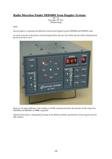
The DDF6000 uses a female 15 pin SUB-D connector:The signals are as follows:AGND01, AGND02 and GND = ground9SW = output signal which controls an attenuator in each channel,(0V = attenuator off, 9V = attenuator on)EA-EH = enable signals for each channel A to H, this is not a rectangular digital signal but in order to have ahigher performance “soft switching” <strong>Doppler</strong> based radio direction finder the signal has slopes,(0V channel enabled, 9V channel disabled)4ANT = control input to determine whether a 4 antenna array or a 8 antenna array is connected(open = 4 antenna mode, externally connected to ground = 8 antenna mode)9V1 = output providing +9V DC supply to the 4 antenna array electronics9V2 = output providing +9V DC supply (not use for 4 antenna arrays, connect externally to 9V1 when usingan 9 antenna array)2/6
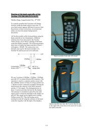
The <strong>DDF6001</strong> uses a male 15 pin SUB-D connector:The signals are as follows:AGND = groundSWAT = output signal which controls an attenuator in each channel, (0V = attenuator off, 9V = attenuator on)in <strong>DDF6001</strong> an additional inverter is built into the RF summer to generate a signal SWATT\ whichactually changes the biasing of the used GaAs MMIC amplifier and switches it either on or in a bypassmode (which corresponds to attenuator on)SWA-SWH = enable signals for each channel A to H, 4 channels A,C,E,G are combined in one unit (Phase A),the other 4 channels B,D,F,H are combined in the other unit (Phase B), most likely (to be confirmed)this is not a rectangular digital signal but in order to have a higher performance “soft switching”<strong>Doppler</strong> based radio direction finder the signal has slopes, 9V channel enabled, 0V channel disabledEA = enables block A of 4 ports (Phase A), EA=0V Phase A disabled, EA=9V Phase A enabled4ANT = control input to determine whether a 4 antenna array or a 8 antenna array is connected(open = 4 antenna mode, externally connected to ground = 8 antenna mode)EB = enables block B of 4 ports (Phase B), EB=0V Phase B disabled, EB=9V Phase B enabled+9V = output providing +9V DC supplySPARE = not used but blocked with a capacitor to ground3/6
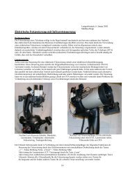
The summing circuits of DDF6000 and <strong>DDF6001</strong> are quite different. The description of the DDF6000 unit canbe found on another article previously posted.For the <strong>DDF6001</strong> there are two families of RF summers available: one family is intend to be used at stationarysetups and supports an array of 8 antennas, the other family is mostly intended for mobile setups and supports anarray of 4 antennas. Both are connected to the above mentioned port J8 (RF summer).Here are descriptions for a 4 antenna setup. First the description of the necessary interconnections:The DDF6244 4-Element RF Summer Assembly is most likely exactly one half of the DDF6223 8-Element RFSummer Assembly which is described later in this document.This is the description of the DDF6247 Mobile Control Cable which connects the main unit to the RF SummerAssembly:4/6
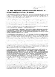
Here are descriptions for an 8 antenna setup. First the description of the necessary interconnections:Here is the DDF6223 8-Element RF Summer AssemblyHere is the description of the DDF6260 Fixed Site Control Cable which connects the main unit to the RFsummer assembly:5/6
Finally here is the schematic for the two units DSA6223.SCH and DSB6223.SCH inside the unit DDF6223:I always appreciate feedback and suggestions for improvements. Please send them to the Email address below.Best regardsMatthias<strong>DD1US</strong>Email: <strong>DD1US</strong>@AMSAT.ORGHomepage: http://www.dd1us.de6/6