CS2 Central Station Air Handlers.pdf - Dunham-Bush Americas
CS2 Central Station Air Handlers.pdf - Dunham-Bush Americas
CS2 Central Station Air Handlers.pdf - Dunham-Bush Americas

Create successful ePaper yourself
Turn your PDF publications into a flip-book with our unique Google optimized e-Paper software.
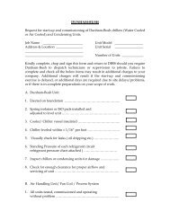
INSTALLATION○ ○ ○ ○ ○ ○ ○ ○ ○ ○ ○ ○ ○ ○ ○ ○ ○ ○ ○ ○ ○ ○ ○ ○ ○ ○ ○ ○ ○ ○ ○ ○ ○ ○ ○ ○ ○ ○ ○ ○ ○ ○ ○ ○ ○ ○ ○ ○ ○ ○ ○It is very important that the unit be installed in a levelposition to prevent distortion and to insure properdamper operation and coil drainage.Allow sufficient space around the unit for propermaintenance. Major factors to be considered are filterremoval for cleaning or replacement, access to allremovable panels, removal of coils and shaft if evernecessary, lubrication access and motor and beltadjustment.Canvas duct connections should be used between theunit and both supply and return air ducts.Units are furnished with a 1 1/4" M.P.T. drain connectionon the coil connection side of the unit. The drain linefrom the drain pan connection must be adequatelypitched and should have a water seal of sufficient depthto compensate for the air pressure within the unit. (SeeCondensate Drain Traps, page 5.)When the unit is located on the roof, it must bemounted on support beams that span load-bearingwalls. If this is not done, excessive vibration may occurdue to the resiliency of the roof.Fan noise is a function of the fan design, volume flow,pressure, and the efficiency of the fan. Present methodsof measuring fan noise do not evaluate the pure tonesgenerated by some fans and these tones can beobjectionable when radiated into occupied spaces.Therefore, on critical applications we recommend extrasound attenuation in the octave band containing thetone.Motors & DrivesAll units will normally be shipped with motor and driveinstalled.When mounting a motor on the adjustable base(installed on the unit) extreme care should be taken toinsure proper alignment and belt tension.All electrical work should be done in strict accordancewith local codes and regulations.Steam CoilsType NFS coils have supply and return connections onthe same end. Types NFO and S coils have supply andreturn connections on opposite ends.Type NFD coils have supply connections on each end ofthe coil, with a single return connection, one end only.All piping should be in accordance with acceptedindustry standards and local codes. Support all pipingindependent of coil and provide adequate swing jointsin all piping to absorb expansion and contraction strains.Run return piping the full size of the coil returnconnection from the coil to a dirt pocket. (Do not usereducing fittings.)Install drip traps in steam mains ahead of coils. Do notdrip steam mains thru the coils.Install a vacuum breaker (1/2" 15° check valve) aheadof the trap on low pressure open gravity return systemsand on high pressure systems. Install a 1/2" 15° swingcheck valve in a 1/2" vacuum equalizing line, bypassingthe condensate trap, on low pressure vacuum systems.When two or more steam coils are furnished in a unit,provide separate traps for each coil. Size traps withample capacity using the maximum heating load andservice factor recommended by the trap manufacturer.Select control valves in accordance with therecommendations of the control manufacturer usingactual heating loads.Install suitable strainers ahead of all automatic valvesand traps to catch dirt and scale.Provide adequate air vents to expel air and other noncondensibles.Control valves used for Type NFS and NFD coils must begradual acting modulating type with Veeport.Where a control valve is used for Type “S” coils andwhen the entering air temperature is below 35°F, use atwo position type valve. Locate control element in theentering air stream so that valve will remain open witha minimum of five pounds steam pressure when theentering air temperature is below 35°F.When the system is started up, the dampers shouldremain closed for approximately ten minutes after thesteam valve is opened.Properly locate all temperature sensing elements at apoint of true average air mixture temperature.Refer to Page 4 for “Typical Steam Coil Piping Diagrams”for controls positioning and piping configuration.When face and bypass dampers are used, it is goodpractice to install on the coil a valve which closes as theface damper closes to prevent overheating due todamper leakage or heat picked up by air wiping theexposed coil face.3