CS2 Central Station Air Handlers.pdf - Dunham-Bush Americas
CS2 Central Station Air Handlers.pdf - Dunham-Bush Americas
CS2 Central Station Air Handlers.pdf - Dunham-Bush Americas

You also want an ePaper? Increase the reach of your titles
YUMPU automatically turns print PDFs into web optimized ePapers that Google loves.
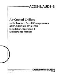
○ ○ ○ ○ ○ ○ ○ ○ ○ ○ ○ ○ ○ ○ ○ ○ ○ ○ ○ ○ ○ ○ ○ ○ ○ ○ ○ ○ ○ ○ ○ ○ ○ ○ ○ ○ ○ ○ ○ ○ ○ ○ ○ ○ ○ ○ ○ ○ ○ ○ ○ ○ ○ ○ ○ ○ ○ ○ ○ ○ ○ ○ ○ ○ ○ ○ ○ ○○ ○ ○ ○ ○ ○ ○ ○ ○ ○ ○ ○ ○ ○ ○ ○ ○ ○ ○ ○ ○ ○ ○ ○ ○ ○ ○ ○ ○ ○ ○ ○ ○ ○ ○ ○ ○ ○ ○ ○ ○ ○ ○ ○ ○ ○ ○ ○ ○ ○ ○ ○ ○ ○ ○ ○ ○ ○ ○ ○ ○ ○ ○ ○ ○ ○ ○ ○ ○○ ○ ○ ○ ○ ○ ○ ○ ○ ○ ○ ○ ○ ○ ○ ○ ○ ○ ○ ○ ○ ○ ○ ○ ○ ○ ○ ○ ○ ○ ○ ○ ○ ○ ○ ○ ○ ○ ○ ○ ○ ○ ○○CS 2<strong>Central</strong> <strong>Station</strong> <strong>Air</strong> <strong>Handlers</strong>Double Wall & Single WallInstallation, Operation &Maintenance ManualForm No. 6120A○ ○ ○ ○ ○ ○ ○ ○ ○ ○ ○ ○ ○ ○ ○ ○ ○ ○ ○ ○ ○○
TABLE OF CONTENTS○ ○ ○ ○ ○ ○ ○ ○ ○ ○ ○ ○ ○ ○ ○ ○ ○ ○ ○ ○ ○ ○ ○ ○ ○ ○ ○ ○ ○ ○ ○ ○ ○ ○ ○ ○ ○ ○ ○ ○ ○ ○ ○ ○PageInspection.................................................................................................................................................... 2Shipment of Units ....................................................................................................................................... 2Handling ...................................................................................................................................................... 2Installation ............................................................................................................................................... 3-5Motors & Drives............................................................................................................................................3Steam Coils............................................................................................................................................... 3-4Water Piping.................................................................................................................................................4Direct Expansion........................................................................................................................................... 4Start-Up ........................................................................................................................................................4Maintenance ............................................................................................................................................5-7Condensate Drain Traps................................................................................................................................5Internally Isolated Units ................................................................................................................................5Section to Section Assembly ........................................................................................................................6Water Coils Exposed to Freezing Temperatures ............................................................................................7Draining Coils Using Supplemental <strong>Air</strong> Blower .............................................................................................7Installation of Anti-Freeze Solution .............................................................................................................. 7Net Weights ................................................................................................................................................. 8Type FS, AS & Accessories Weights ............................................................................................................... 8ODP "T" Frame Motor & Adjustable Drive Weights........................................................................................8Water Coil Operating Weights ...................................................................................................................... 8Steam & Water Coil Connection Sizes & Locations ....................................................................................... 8Filter Arrangements ...............................................................................................................................9-11Angle Filter ................................................................................................................................................... 9Bag/Cartridge Filter..................................................................................................................................... 10Flat Filter .................................................................................................................................................... 11Top View of Side Wall Double Wall Construction ..................................................................................... 12Shipping Modules ..................................................................................................................................... 13INSPECTION & HANDLING○ ○ ○ ○ ○ ○ ○ ○ ○ ○ ○ ○ ○ ○ ○ ○ ○ ○ ○ ○ ○ ○ ○ ○ ○ ○ ○ ○ ○ ○ ○ ○ ○ ○ ○ ○ ○ ○ ○ ○InspectionHandlingShipment should be checked against the bill of ladingto verify that all items listed have been received.All parts should be carefully inspected to determine ifany damage was incurred in shipment.Any shortages and/or claims for damage should beimmediately reported to the delivering carrier followedby filing a claim for shortages and/or damages.Shipment of UnitsSpecial care should be taken when handling andassembling component sections of the unit. Roughhandling at the job site can result in damaged bearings,bent shaft, etc.All units are shipped on wooden skids. It isrecommended that units not be removed from skidsuntil they are at place of installation. The mountinglegs/rails provided for isolators should be used whenlifting units into place.2Depending on the unit size and accessories included,the shipment may be made in two or more sections.
INSTALLATION○ ○ ○ ○ ○ ○ ○ ○ ○ ○ ○ ○ ○ ○ ○ ○ ○ ○ ○ ○ ○ ○ ○ ○ ○ ○ ○ ○ ○ ○ ○ ○ ○ ○ ○ ○ ○ ○ ○ ○ ○ ○ ○ ○ ○ ○ ○ ○ ○ ○ ○It is very important that the unit be installed in a levelposition to prevent distortion and to insure properdamper operation and coil drainage.Allow sufficient space around the unit for propermaintenance. Major factors to be considered are filterremoval for cleaning or replacement, access to allremovable panels, removal of coils and shaft if evernecessary, lubrication access and motor and beltadjustment.Canvas duct connections should be used between theunit and both supply and return air ducts.Units are furnished with a 1 1/4" M.P.T. drain connectionon the coil connection side of the unit. The drain linefrom the drain pan connection must be adequatelypitched and should have a water seal of sufficient depthto compensate for the air pressure within the unit. (SeeCondensate Drain Traps, page 5.)When the unit is located on the roof, it must bemounted on support beams that span load-bearingwalls. If this is not done, excessive vibration may occurdue to the resiliency of the roof.Fan noise is a function of the fan design, volume flow,pressure, and the efficiency of the fan. Present methodsof measuring fan noise do not evaluate the pure tonesgenerated by some fans and these tones can beobjectionable when radiated into occupied spaces.Therefore, on critical applications we recommend extrasound attenuation in the octave band containing thetone.Motors & DrivesAll units will normally be shipped with motor and driveinstalled.When mounting a motor on the adjustable base(installed on the unit) extreme care should be taken toinsure proper alignment and belt tension.All electrical work should be done in strict accordancewith local codes and regulations.Steam CoilsType NFS coils have supply and return connections onthe same end. Types NFO and S coils have supply andreturn connections on opposite ends.Type NFD coils have supply connections on each end ofthe coil, with a single return connection, one end only.All piping should be in accordance with acceptedindustry standards and local codes. Support all pipingindependent of coil and provide adequate swing jointsin all piping to absorb expansion and contraction strains.Run return piping the full size of the coil returnconnection from the coil to a dirt pocket. (Do not usereducing fittings.)Install drip traps in steam mains ahead of coils. Do notdrip steam mains thru the coils.Install a vacuum breaker (1/2" 15° check valve) aheadof the trap on low pressure open gravity return systemsand on high pressure systems. Install a 1/2" 15° swingcheck valve in a 1/2" vacuum equalizing line, bypassingthe condensate trap, on low pressure vacuum systems.When two or more steam coils are furnished in a unit,provide separate traps for each coil. Size traps withample capacity using the maximum heating load andservice factor recommended by the trap manufacturer.Select control valves in accordance with therecommendations of the control manufacturer usingactual heating loads.Install suitable strainers ahead of all automatic valvesand traps to catch dirt and scale.Provide adequate air vents to expel air and other noncondensibles.Control valves used for Type NFS and NFD coils must begradual acting modulating type with Veeport.Where a control valve is used for Type “S” coils andwhen the entering air temperature is below 35°F, use atwo position type valve. Locate control element in theentering air stream so that valve will remain open witha minimum of five pounds steam pressure when theentering air temperature is below 35°F.When the system is started up, the dampers shouldremain closed for approximately ten minutes after thesteam valve is opened.Properly locate all temperature sensing elements at apoint of true average air mixture temperature.Refer to Page 4 for “Typical Steam Coil Piping Diagrams”for controls positioning and piping configuration.When face and bypass dampers are used, it is goodpractice to install on the coil a valve which closes as theface damper closes to prevent overheating due todamper leakage or heat picked up by air wiping theexposed coil face.3
Typical Steam Coil Piping DiagramsLOW PRESSURE OPEN GRAVITY RETURN SYSTEM12" MINUNIONVENTHIGH PRESSURE SYSTEMWater Piping12" MINUNIONVENTSTEAM MAINGATE VALVESTRAINERCONTROL VALVEVACUUM BRKR1/2" 15°CHK. VALVEGATE VALVEUNIONCOMBINATIONFLOAT ANDTHERMOSTATICUNION TRAPSTRAINERDIRT POCKETRETURN MAINSTEAM MAINGATE VALVESTRAINERCONTROL VALVEUNIONFLOAT ORBUCKET TRAPUNIONSTRAINERDIRT POCKETRETURN MAINOPENVENTAll piping must be supported independent of coils.Swing joints or flexible fittings must be provided toabsorb expansion and contraction strains. Rigid pipingmay also reduce effectiveness of vibration isolators.The water supply should always be connected to thebottom inlet of the coil. The coil connections areidentified with stickers.Direct ExpansionBoth the liquid distributor and the suction line extendthru the casing.The expansion valve utilized must be of the externalequalizer tube type. The expansion valve bulb must belocated on the suction line between the coil and the1/4" external equalizer tube. Never locate the bulb in atrap.All refrigerant piping practices used should be inaccordance with local codes and latest ANSI StandardB9 Safety Code. Hard drawn type “L” or “K” coppertubing should be used. Soft tubing where bending isrequired may be used provided it is protected inaccordance with local code restrictions.Good practices should be followed as to pullingadequate vacuum, tubes cleaned of foreign material,etc.Start-UpMake sure all bolts and screws are tight.Remove tagged shipping tie down bolts and spacersfrom the fan and motor assembly before start-up. Referto page 5.Check the sheaves to see if they are in alignment andmake sure the set screws are tight. Make sure that thedimension across the top is equal on all grooves,otherwise excessive belt wear will result.Check for proper rotation of the blower pulley. Threephase motor rotation can be reversed by exchangingtwo of the three leads at the motor starter. The rotationof single phase motors can be reversed by exchangingleads inside the motor junction box. Refer to thediagram on the motor.Check the amperage draw of the motor. This shouldnot exceed the nameplate amps shown on the motorserial plate.After approximately two weeks of operation, the beltswill have nearly acquired their permanent stretch. Afterthis interval, the belt tension should be checked againand proper adjustment made.Water coils, 3 thru 10 rows, are supplied with a ventand drain connection (1/4" MPT) which extends thruthe unit casing.For protection of coils exposed to freezing temperatures,refer to page 7.Coils must be adequately vented in order to prevent airbinding.4
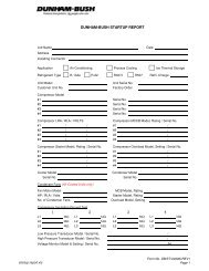
MAINTENANCE○ ○ ○ ○ ○ ○ ○ ○ ○ ○ ○ ○ ○ ○ ○ ○ ○ ○ ○ ○ ○ ○ ○ ○ ○ ○ ○ ○ ○ ○ ○ ○ ○ ○ ○ ○ ○ ○ ○ ○ ○ ○ ○ ○ ○ ○ ○ ○ ○ ○The belt tension should be checked at three-monthintervals.Re-lubricable bearings mounted inside the fan sectionhave extended lubrication lines which are mounted onthe outside of the fan panels. The suggested greasinginterval is indicated on a sticker attached to the unit.It is recommended that bearings be lubricated with ahigh quality lithium base grease at intervals indicatedon sticker attached to the unit.Instructions are included on the motor nameplate forlubricating the motor bearings.The filters should be periodically inspected and replacedor cleaned when necessary. Dirty filters reduce the airflow which reduces the capacity of the system. Do notoperate system without filters.All CS 2 Units are Internally IsolatedIsolators are installed and adjusted at the factory.Brackets and bolts tie down the fan and motor assemblyfor shipment. Remove tie down bolts before start-up.Refer to page 4 for clarification.Remove the bolt from bracket to motor support base,then loosen bolts to frame and slide bracket to end ofslot so bracket is not in contact with the motor supportbase. The bracket then acts as a snubber on fan startup.END RAILMOTOR BASE SUPPORT(4) SHIPPING BRACE /SNUBBER(DO NOT DISCARD)Lube inlet vanes and/or damper linkage annually.Check for drain clogging several times a year.Clean coils and drain pans as necessary.Condensate Drain TrapsThe condensate drain trap piping must be properlydesigned to insure the removal of condensate. Incorrecttrapping can hold water in pan causing overflow. Onblow thru units, particularly, system air can escape downthe drain with incorrect trapping.ISOLATORISOLATOR RAILCONDENSATE DRAIN TRAP(AIR SEAL)1¼" PIPE DRAIN CONNECTIONAB(a) On draw-thru units (A) shall be equal to or greaterthan the coil sections negative pressure at operatingconditions.(b) On blow-thru units (A) can be as small as 1" but (B)must equal or exceed the total static pressure inthe coil section.5
Section to Section AssemblyHEX HEAD BOLTFLAT WASHERMOUNTING BRACKETMOUNTING BRACKETFLAT WASHERHEX NUTDETAIL "A"AHU SECTIONAHU SECTION6
Water Coils Exposed To FreezingTemperaturesWater coils exposed to freezing temperatures must beprotected from freeze-up by either adding an anti-freezesolution to the coils or by proper draining of the coils.<strong>Dunham</strong>-<strong>Bush</strong> coils are circuited to avoid trappedcircuits. However, because of the serpentine nature ofthe circuiting, it is almost impossible to adequately drainthe coils by gravity alone. Particularly on longer finnedlength coils, even a fraction of a degree deviation froma horizontal plane can lead to water being trappedwithin the serpentine. Water that has failed to drainfrom a single tube, or even part of a tube, can causethe tube to rupture upon freezing.Draining Coils Using Supplemental <strong>Air</strong>BlowerIdeally, a blower capable of delivering 150 CFM of airat approximately 40-50 inches of water or more shouldbe used. Some small air compressors, while deliveringhigher pressure, probably will not deliver sufficientvolume of air and this is equally as important.1. Drain the coil by gravity after opening the supply,return, vent and drain connections.2. Connect the blower to the larger connection that isat the greatest elevation. The small vent or drainconnection on the header to which the blower isconnected should be closed. Refer to Figure 1 fortypical hook-up during the blow-out operation. It ishelpful to tap the coil casing along the length of thecoil during the draining process. The blower shouldbe operated until no moisture can be detected leavingthe coil. Then, shut the blower off and permit thecoil to stand for a few minutes. This will permit themoisture that has adhered to the walls to accumulate.Then the blowing out operation should be repeated.Ideally, the coil should be permitted to stand twentyfour(24) hours and then be blown out again.3. Leave all connections open until coil is put intooperation.Installation Of Anti-freeze SolutionA second way to prevent a coil freeze-up is to add ananti-freeze to coil such as industrially inhibited glycol.The coil should be valved off so that only the coil wouldhave anti-freeze added to it. The most positive way toassure the mixing of the anti-freeze is to make a runaroundloop with a circulating pump.1. Open all connections and drain the coil as thoroughlyas possible.2. The anti-freeze solution should be added to the coiland circulated through the coil until the solution isthoroughly mixed and all air is purged from the coil.The air vent should be opened during the fillingoperation and cracked during the pumping operationto accomplish this. When the solution has circulatedfor 15-20 minutes, the concentration of the solutionshould be checked with a suitable hydrometer. Ifthe concentration is low, add more glycol and operatethe pump again. Refer to Figure 2 for a typical pipingdiagram.3. The anti-freeze solution may then be left in the coilsor drained and used to flush another coil. Theconcentration must be checked for each coil flushed.The addition of anti-freeze to a system exposed tofreezing conditions may be necessary if the system mustbe operational at a moment’s notice. This affects thechiller and coil performance and must be taken intoconsideration when selecting components.NOTE:Most anti-freeze solutions will be furnished with a chartfor concentration at freezing point. It is also importantto be certain that the anti-freeze solution used is notcorrosive to the tubing. If this information is notavailable, consult <strong>Dunham</strong>-<strong>Bush</strong>.Figure 1Blower Supplemented Coil DrainingFigure 2Typical Piping Diagram forAdding Anti-Freeze SolutionHorizontal <strong>Air</strong> FlowBlower*VentAIRFLOWOutVentAIR FLOW*DrainOpen DuringBlowing OperationVertical <strong>Air</strong> Flow*VentAIR FLOWGLYCOLSOLUTIONCirculatingPumpDrainInOpen DuringBlowing OperationBlower*Drain7
NET WEIGHTS ○ ○ ○ ○ ○ ○ ○ ○ ○ ○ ○ ○ ○ ○ ○ ○ ○ ○ ○ ○ ○ ○ ○ ○ ○ ○ ○ ○ ○ ○ ○ ○ ○ ○ ○ ○ ○ ○ ○ ○ ○ ○ ○ ○ ○ ○ ○ ○ ○ ○8Model Size 12 22 30 40 48 64 80 100 120 150 180 240 270 320 420 480 590Basic unit: FS TypeHorizontal 449 628 733 967 1022 1114 1470 1825 2039 2539 2910 3872 4140 4431 — — —Single Wall Vertical 402 626 698 940 1040 1382 1636 2129 2549 2810 3690 4435 4850 5320 — — —Fan Section 239 402 466 590 592 677 947 1286 1380 1853 2097 2712 2890 3068 — — —Horizontal 466 656 767 1001 1065 1190 1582 1939 2138 2653 3026 4005 4300 4598 — — —Double Wall Vertical 404 663 737 998 1099 1453 1729 2248 2684 2969 3833 4592 5099 5610 — — —Fan Section 249 427 489 610 618 724 1020 1367 1450 1937 2181 2805 2990 3181 — — —Basic unit: AF TypeHorizontal — — — 1013 1132 1336 1622 1977 2241 2767 3159 4227 4791 5360 7163 8447 9193Single Wall Vertical — — — 989 1140 1604 1788 2281 2751 3038 3939 4797 8632 6248 — — —Fan Section — — — 636 692 899 1099 1438 1582 2081 2346 3848 3912 3997 5335 6330 6475Horizontal — — — 1047 1165 1412 1734 2091 2340 2881 3295 4330 4890 5526 7665 8371 9400Double Wall Vertical — — — 1045 1199 1675 1881 2400 2886 3197 4082 4954 5700 6547 — — —Fan Section — — — 657 718 946 1172 1519 1652 2165 2430 3143 3632 4109 5709 6543 6621AccessoriesDiffuser Sect. 27 91 119 173 202 226 230 295 401 431 588 613 827 1015 1194 1303 1710 1865Coil Module with Drain Pan(without Coil) Sect. 8146 209 260 326 364 395 476 481 517 735 844 1011 1102 1194 1303 1710 1865External Face & Bypass(without Duct) Sect. 2071 91 93 106 119 146 187 217 233 337 350 628 683 690 820 835 912Internal Face & Bypass Sect. 17 11 21 26 30 41 53 64 80 96 119 146 189 221 254 321 364 444Preheat SectionWithout Coil Sect. 657 75 79 92 103 121 161 187 201 294 307 552 570 597 652 721 746Flat and Bag Filter Section(without Filters) Sect. 10 or 13171 224 236 277 308 333 402 441 474 587 613 827 857 895 977 1026 1119Angle Filter Section(without Filters) Sect. 11 & 23125 164 173 202 225 244 294 323 347 404 423 552 575 597 651 684 746Combination Mixing & FilterSection (without Filters) Sect. 16C137 179 251 294 328 364 482 535 574 808 844 1103 1233 1393 1629 2052 2237Mixing Box Sect. 16 91 119 173 202 225 244 294 401 431 587 613 1011 1100 1194 1303 1710 1864Section 9 Single Wall — 600 682 808 848 1021 1214 1370 1757 2160 2511 3148 3373 3599 4294 5440 6642Multizone Double Wall — 756 860 1009 1060 1338 1542 1712 2196 2705 3139 3934 4216 4499 5.26 6746 8235ODP “T” Frame Motor & Adjustable Drive WeightsT - Frame 143 145 182 184 213 215 254 256 284 286 324 326 364 365Motor HP - 1750 RPM 1 1.5 & 2 3 5 7.5 10 15 20 25 30 40 50 60 75Motor Weight in Lbs. 30 38 56 70 127 141 187 211 263 300 409 460 560 648Drive Weight in Lbs. 25 27 30 35 45 52 66 74 85 96 108 136 265 354Water Coil Operating Weights (lbs) - LFAUnitRowsSize 1A 2A 3A 4A 6A 8A 10A12 32 44 56 68 95 122 14922 42 58 76 93 131 169 20830 52 74 99 122 173 224 27640 69 103 139 173 248 323 39848 76 113 154 191 275 358 44264 96 147 202 253 366 478 59080 110 171 237 298 431 565 698100 130 206 286 361 525 688 852120 147 235 327 416 605 794 983150 173 281 395 503 734 965 1196180 212 351 495 634 928 1222 1516240* 266 448 636 818 1200 1582 1965270* 298 506 721 929 1364 1799 2234320* 368 610 863 1105 1618 2131 2644420* 438 737 1048 1347 1978 2608 3239480* 552 898 1262 1606 2346 3088 3828590* 656 1064 1488 1896 2764 3632 4501* = Total of 2 Stacked CoilsSteam & Water Coil Connection Sizes & LocationsMale LocationIron Pipe Size Steam Water*Supply Return S NFS NFD 1R 2R 3R 4R 5R 6R 8R 10RSteam Type S 1 Row 1.5 1.25 O.E. S.E. #Coils Type S 2 Rows 2.5 1.50 O.E. S.E. #WH 1.5 1.50 — — — S.E. S.E. S.E. S.E. S.E. S.E. — —WF - 1 & 2 Rows 1.5 1.50 — — — O.E. S.E. — — — — — —Water WF - 3-10 Rows 2.0 2.00 — — — — — O.E. S.E. O.E. S.E. S.E. S.E.Coils WD 2.5 2.50 — — — — — S.E. O.E. S.E. O.E.WP 1.5 1.50 — — — — — S.E. S.E. S.E. S.E. S.E. —WQ 2.5 2.50 — — — — — — — S.E. S.E. S.E. S.E.#5 NFD coils have (2) supply connections on opposite ends and (1) return connection.*All water coils with 37 tubes in face or more will be stacked, separate coils.
SHIPPING MODULES ○ ○ ○ ○ ○ ○ ○ ○ ○ ○ ○ ○ ○ ○ ○ ○ ○ ○ ○ ○ ○ ○ ○ ○ ○ ○ ○ ○ ○ ○ ○ ○ ○ ○ ○ ○ ○ ○ ○ ○ ○ ○ ○ ○ ○The CS 2 offers flexibility for splitting the unit into as many (or few) shipment modules as desired. However, sizes 240 andlarger are usually too large to allow one piece shipment because unit width exceeds truck width. The CS 2 can be split intomodules at as many section to section joints as desired with the following considerations:1. Wide load shipping costs are required over 102". It is not practical to ship over 144" width. Therefore, the unit mustbe separated to minimize module length (in direction of air flow) and, therefore, shipping cost.2. Installation cost is generally proportional to the number of modules.3. Internal/external connecting brackets are utilized. Therefore, the CS 2 cannot be split between two coil sections,because flanges are not accessible from either direction.The following examples illustrate shipping options and assembled unit length:EXAMPLE: SIZE 320UNIT ASSEMBLY3 PIECE SHIPMENT(Maintain 102" maximum module lengthand standard freight cost)2 PIECE SHIPMENT(Maintain 144" maximum module lengthusing wide load freight cost)COOL-MIXBOXBAGFILTERCOOL-INGMIXBOXBAGFILTERINGCOILCOILHORIZONTALFANHORIZONTALFAN56.00 36.00 24.00 70.0056.00 36.0024.00 70.00Installed unit length = 186.00 Installed unit length = 186.00Assembled length = (nominal section lengths + (1.7)"(number of splits)2 PIECE TRUCK LOADING (Must pay "wide load" premium)Fan & Cooling Coil109.7 x 151.5Mix Box & Bag Filter109.7 x 151.5CS 2 unit sizes 17 thru 65 can be shipped in one piece. The overall length of the requested sections(i.e. filters, mixing box, access section, etc.) determines if the total unit can be shipped in onepiece. Units that exceed twelve (12) feet in direction of airflow will ship in two sections. Thedesign of the CS 2 allows the customer to dictate the number of individual sections of the unit.Consult factory where specific shipping assemblies must be furnished.COMPONENTS & DESIGN—SUBJECT TO CHANGE WITHOUT NOTICE.13
October 2000101 Burgess RoadHarrisonburg, VA 22801(540) 434-0711, FAX (540) 434-4595Form 6120A