Teryx 750 EFI Dyna FS Ignition
Teryx 750 EFI Dyna FS Ignition
Teryx 750 EFI Dyna FS Ignition
- No tags were found...

You also want an ePaper? Increase the reach of your titles
YUMPU automatically turns print PDFs into web optimized ePapers that Google loves.
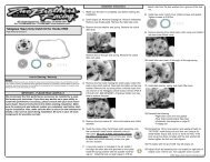
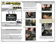
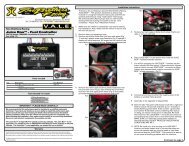
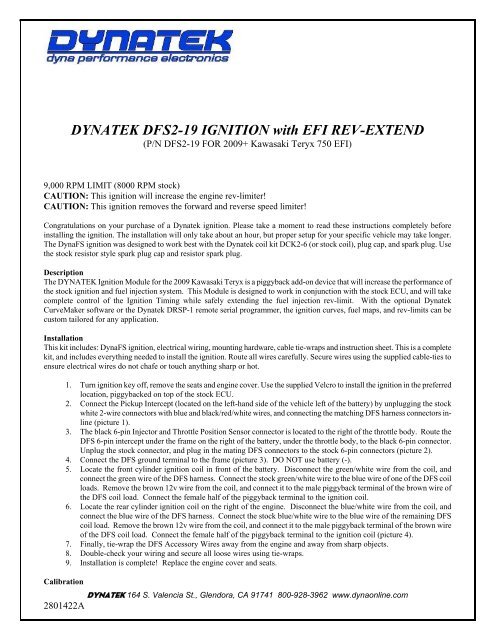
DYNATEK D<strong>FS</strong>2-19 IGNITION with <strong>EFI</strong> REV-EXTEND(P/N D<strong>FS</strong>2-19 FOR 2009+ Kawasaki <strong>Teryx</strong> <strong>750</strong> <strong>EFI</strong>)9,000 RPM LIMIT (8000 RPM stock)CAUTION: This ignition will increase the engine rev-limiter!CAUTION: This ignition removes the forward and reverse speed limiter!Congratulations on your purchase of a <strong>Dyna</strong>tek ignition. Please take a moment to read these instructions completely beforeinstalling the ignition. The installation will only take about an hour, but proper setup for your specific vehicle may take longer.The <strong>Dyna</strong><strong>FS</strong> ignition was designed to work best with the <strong>Dyna</strong>tek coil kit DCK2-6 (or stock coil), plug cap, and spark plug. Usethe stock resistor style spark plug cap and resistor spark plug.DescriptionThe DYNATEK <strong>Ignition</strong> Module for the 2009 Kawasaki <strong>Teryx</strong> is a piggyback add-on device that will increase the performance ofthe stock ignition and fuel injection system. This Module is designed to work in conjunction with the stock ECU, and will takecomplete control of the <strong>Ignition</strong> Timing while safely extending the fuel injection rev-limit. With the optional <strong>Dyna</strong>tekCurveMaker software or the <strong>Dyna</strong>tek DRSP-1 remote serial programmer, the ignition curves, fuel maps, and rev-limits can becustom tailored for any application.InstallationThis kit includes: <strong>Dyna</strong><strong>FS</strong> ignition, electrical wiring, mounting hardware, cable tie-wraps and instruction sheet. This is a completekit, and includes everything needed to install the ignition. Route all wires carefully. Secure wires using the supplied cable-ties toensure electrical wires do not chafe or touch anything sharp or hot.1. Turn ignition key off, remove the seats and engine cover. Use the supplied Velcro to install the ignition in the preferredlocation, piggybacked on top of the stock ECU.2. Connect the Pickup Intercept (located on the left-hand side of the vehicle left of the battery) by unplugging the stockwhite 2-wire connectors with blue and black/red/white wires, and connecting the matching D<strong>FS</strong> harness connectors inline(picture 1).3. The black 6-pin Injector and Throttle Position Sensor connector is located to the right of the throttle body. Route theD<strong>FS</strong> 6-pin intercept under the frame on the right of the battery, under the throttle body, to the black 6-pin connector.Unplug the stock connector, and plug in the mating D<strong>FS</strong> connectors to the stock 6-pin connectors (picture 2).4. Connect the D<strong>FS</strong> ground terminal to the frame (picture 3). DO NOT use battery (-).5. Locate the front cylinder ignition coil in front of the battery. Disconnect the green/white wire from the coil, andconnect the green wire of the D<strong>FS</strong> harness. Connect the stock green/white wire to the blue wire of one of the D<strong>FS</strong> coilloads. Remove the brown 12v wire from the coil, and connect it to the male piggyback terminal of the brown wire ofthe D<strong>FS</strong> coil load. Connect the female half of the piggyback terminal to the ignition coil.6. Locate the rear cylinder ignition coil on the right of the engine. Disconnect the blue/white wire from the coil, andconnect the blue wire of the D<strong>FS</strong> harness. Connect the stock blue/white wire to the blue wire of the remaining D<strong>FS</strong>coil load. Remove the brown 12v wire from the coil, and connect it to the male piggyback terminal of the brown wireof the D<strong>FS</strong> coil load. Connect the female half of the piggyback terminal to the ignition coil (picture 4).7. Finally, tie-wrap the D<strong>FS</strong> Accessory Wires away from the engine and away from sharp objects.8. Double-check your wiring and secure all loose wires using tie-wraps.9. Installation is complete! Replace the engine cover and seats.CalibrationDYNATEK 164 S. Valencia St., Glendora, CA 91741 800-928-3962 www.dynaonline.com2801422A
The <strong>Dyna</strong><strong>FS</strong> is pre-programmed with a single performance advance curve, +4° over stock, and a 9,000 RPM rev-limit. A quickerthrottle response and increased power over the stock curve is achieved. For other advance curve information, see the CurveMakersoftware. This ignition will allow the engine to rev to a higher RPM, and is adjustable to 10,000 RPM max by using theCurveMaker software. Because the rev limit is increased, the performance limits of other engine parts (valve train, piston orcrankshaft, for example) may be found. It may be necessary to replace these parts for best engine performance. The D<strong>FS</strong>2-19 isshipped from <strong>Dyna</strong>tek with 0% adjustments to all of the fuel injection settings. For more information on fuel settings, see thesection on Using the DRSP-1 Remote Programmer.Picture 1: Crankshaft Position Sensor connectionLocated left of the batteryPicture 2: Injector and Throttle Position Sensor connectionLocated right of the throttle bodyPicture 3: Ground connectionLocated right of the batteryPicture 4: Rear <strong>Ignition</strong> CoilLocated right of engineDYNATEK 164 S. Valencia St., Glendora, CA 91741 800-928-3962 www.dynaonline.com2801422A
Using the DRSP-1 Remote Serial ProgrammerThe DRSP-1 Remote Serial Programmer (sold separately) for the Kawasaki <strong>Teryx</strong> <strong>750</strong> is a plug-in programmer for adjustingthe fuel injection and ignition advance curves. Simply plug the DRSP-1 into the D<strong>FS</strong> HARNESS and mount the Remote tothe vehicle’s dashboard for easy access. The Remote allows adjustment to the stock fuel injections signal in multiple stages.NOTE: It is HIGHLY RECOMMENDED to use a wide band oxygen sensor and quality gauge (such as Dynojet’s Wide BandCommander) when tuning the fuel injection. Without a gauge, the air/fuel ratio cannot be determined and possible enginedamage can occur.FUEL BASE – this setting will adjust the entire fuel map: 1 = 0% 2 = Full Exhaust 3 = Slipon Exhaust 4 = StockFUEL LOW – this setting will adjust fuel from 0 rpm to 3,000 rpm, in the ranges of: -17.5% to 0% to +20%FUEL MID – this setting will adjust fuel from 3,001 rpm to 6,000 rpm, in the ranges of: -17.5% to 0% to +20%FUEL HIGH – this setting will adjust fuel above 6,000 rpm, in the ranges of: -17.5% to 0% to +20%IGN CURVE – this setting will adjust the <strong>Ignition</strong> Curve, up to 4 selectable and all can be custom programmed using theCurveMaker Software. (see attached Curve Chart)NOTE: The DRSP-1 can be removed after adjusting the settings, and the <strong>Dyna</strong><strong>FS</strong> will keep the settings even with the batterydisconnected. If the LED on the Remote does not turn on, or the LED flashes continuously after 10 seconds, then the ignitionand Remote should be returned to <strong>Dyna</strong>tek for testing.Additional FeatureThe D<strong>FS</strong> for the Kawasaki <strong>Teryx</strong> <strong>750</strong> has a RPM window switch output. This is pre-programmed and can be accessed using<strong>Dyna</strong>tek CurveMaker Software (not supplied with the ignition). If the ignition was not purchased directly from <strong>Dyna</strong>tek, the dealermay have programmed a custom set of ignition curves and fuel injection settings. The dealer should be consulted with anyquestions regarding the curves and settings that are programmed into the ignition.The D<strong>FS</strong> ignition for the Kawasaki <strong>Teryx</strong> <strong>750</strong> is shipped with an additional lead coming out of the ignition. This lead allows theignition to control other features. To program these features, follow the instructions in the programming kit.BLUE – Optional 1/4-amp RPM window activated switch to ground, referenced as “RPM Switch 1” in the CurveMaker Software.The Blue wire is a 1/4-amp switch that can be used to activate a shift light or relay. Connect the relay with hot +12v wired to oneside of the relay coil, and the other side connected to Blue. When the rpm activates the switch, it will be grounded inside theignition box, causing current to flow through the relay coil. DO NOT connect any device which requires more than 1/4 Amp(Amps=Volts/Resistance). See attached wiring diagram for wiring the relay.Data RecordingThe D<strong>FS</strong>2-19 for the Kawasaki <strong>Teryx</strong> <strong>750</strong> will continuously record important engine operating parameters. This information canonly be accessed through the <strong>Dyna</strong>tek CurveMaker in the Diagnostics Tab of the software (sold separately). The recorded dataincludes:Number of Engine Starts (recorded after 2.25min of run time)Total Time Engine at WOT (hours)Total Operating Time (hours)Longest Continuous WOT Operation (seconds)Histograph Barchart of Engine Speed VS. TimeMaximum Engine SpeedTime Near Rev LimitProgrammed Rev LimitDYNATEK 164 S. Valencia St., Glendora, CA 91741 800-928-3962 www.dynaonline.com2801422A
TroubleshootingTroubleshooting the <strong>Dyna</strong> ignition is simple. If the dashboard “Check Engine Light” is ON, or the vehicle will not start or run atall, follow these steps:1) Disconnect the Fuel Injector Intercept connector and reconnect the stock connector to the fuel injector,2) Disconnect the D<strong>FS</strong> ignition coil connectors, and reconnect the stock connector.If this fixes the problem, then the <strong>Dyna</strong> ignition should be returned to <strong>Dyna</strong>tek for testing. If this does not fix the problem, thenthe problem is somewhere else on the engine or vehicle. Follow the troubleshooting procedures outlined in your vehicle shopmanual.If you are using non stock spark plug, or stator, replace them with OEM units. If the problem persists when using the stockignition then the problem is external to the <strong>Dyna</strong> ignition.CurveMaker bench programming: If you are programming the D<strong>FS</strong>2-19 with CurveMaker while the D<strong>FS</strong> is not on thevehicle, it will be necessary to ground the Pickup Intercept signal at the D<strong>FS</strong> connectors. Connect a jumper between ground(located on the 4 pin connector, the pin nearest the 8 pin connector, on the opposite side from the connector latch) and thepickup signal (located on the 6 pin connector, the pin nearest the 8 pin connector, on the opposite side from the connectorlatch). When viewing the D<strong>FS</strong> 6, 8, and 4 pin connectors with the D<strong>FS</strong> label and connector latch up, this is the lower left pinof the 4 pin connector, and the lower right pin of the 6 pin connector. This jumper must be connected before connecting theCurveMaker programming connector. This jumper will prevent noise on the disconnected pickup input. This noise willcause the D<strong>FS</strong> to ignore CurveMaker communication, and attempt to communicate with the optional DRSP-1 Remote SerialProgrammer. If noise is present, CurveMaker will report “<strong>Ignition</strong> Not Found” when attempting to communicate with theD<strong>FS</strong>2-19.Examples of RPM Activated Switch wiring:SHIFT LIGHT orSMALL SOLENOIDUSING A BOSCH STYLE RELAYTO SWITCH HEAVY LOADS+12VBLUEIGNITION8530BOSCHRELAY87a8786BLUEIGNITIONHIGHCURRENTDEVICEDYNATEK 164 S. Valencia St., Glendora, CA 91741 800-928-3962 www.dynaonline.com2801422A
DYNATEK 164 S. Valencia St., Glendora, CA 91741 800-928-3962 www.dynaonline.com2801422A