Riverside Campus Plan - Office of Facilities Coordination - Texas ...
Riverside Campus Plan - Office of Facilities Coordination - Texas ... Riverside Campus Plan - Office of Facilities Coordination - Texas ...
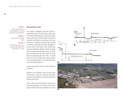
TEXAS A&M UNIVERSITY RIVERSIDE CAMPUS PLAN36FIGURE 1Road section of Avenue Cshowing building set back andbar ditch and road dimensions.FIGURE 2Road section of WarehouseRoad.FIGURE 3Aerial photo of campus showingangle of Warehouse Roadand 2nd Street, ca. 2007.REGULATING PLANThe original overlapping grid plan provides aclearly defined layout for the campus, with a regular400 foot block dimension on centerline for thenorth-south avenues. Block lengths vary between1,000 feet and 500 feet on centerline of the eastweststreets. A 300 foot wide apron, later widenedto 500 feet, with Flight Line Road, designated asthe first 20 feet of the apron, is the western limitto the base buildings. Warehouse Road is alignedwith the original railroad spur, shown as 58 degrees30 minutes from the north-south axis on theGeneral Layout plan dated July 1942. A secondstreet (1st on the 1942 plan, but called 2nd Streeton all subsequent plans) is 350 feet from WarehouseRoad and parallel to it.21Streets are generally 20 feet in width, flanked bybar ditches.Setbacks were uniformly 40 feet from the backof the streets, except for warehouse and hangarstructures where different functional requirementsdictated the set back.The two three-story brick barracks constructed in1958 interrupt the flow of Avenue D. Future developmentshould follow the regulating lines estab-3
COMPONENTS OF THE CAMPUS PLAN37lished in 1942, with setbacks of 40 feet from theoriginal street edge. All existing view and accesscorridors down the streets and avenues should bepreserved.The main administrative and recreational buildings,the Post Exchange, and Chapel were alldesignated on a 450 foot wide block between 5thand 6th Streets. Future development of buildingsserving the Riverside Campus community shouldbe constructed along this east-west spine. Potentiallythese include an administrative and securityoffice building on the site of the HeadquartersWing Building (8007) , general classrooms, andan amenity/assembly building with food serviceto augment the assembly facilities in the Chapel(7006).CIRCULATIONThe major traffic routes have remained remarkablyconsistent since the base was first laid out.The 1942 General Layout indicates ‘Heavy TrafficStreets’ on Avenues A and C and Bryan Road(the entrance road until construction of Highway47) and Warehouse Road and Streets 1, 5 and 6.Flight Line Road (part of the apron) also carriedsignificant traffic.The current circulation is very light traffic, withonly 5th Street paved to any significant quality, aresult of it becoming the connection to New EntranceRoad from Highway 47.In order to establish an effective circulation pattern,priority should be given to re-paving 7thcreased traffic load without requiring the wideningof either street, though the quality of all streetsin the campus should be upgraded. The originalsite drainage using bar ditches and storm drains isacceptable and curbs and gutters should not be requiredprovided regular maintenance is provided.PARKING AND ACCESSProvision for parking was included in the 1942layout, although not generally hard paved. Parkinghas been provided in association with constructionsince 1958, but the low population hasestablished a tradition of parking on the grass atthe side of the roads adjacent to activity zones.As changes take place through new buildings orchange to existing structures, defined and pavedoff-street parking should be a requirement of ap-FIGURE 4A good example of visitor parkinglot and bus service, seenhere at JJ Pickle Research Centerin Austin, Texas.Street and Warehouse Road, and Avenue A andproval, as should proper provision for delivery, re-Bryan Road, creating a loop within the campus.moval of trash and emergency access. The park-6th Street will remain the main axis of the cam-ing surface and site drainage should be consistentpus. Access to Flight Line Road will continue towith an increased formality of the image of thebe from 5th Street and an improved 7th Street.campus. Safety lighting should be considered andThe loop system will facilitate a future bus ser-designed to meet university standards.vice. As activity increases at the Riverside Campus,consideration should be given to improvingWithin the areas of new development, all appro-6th Street and providing for 5th and 6th Streets topriate codes and standards should be met includ-be one-way traffic. This will provide for an in-ing those related to accessibility.4
- Page 1: RIVERSIDE R I E CAMPUS PLANT E X A
- Page 5 and 6: TEXAS A&M UNIVERSITY RIVERSIDE CAMP
- Page 7 and 8: Letters from various administration
- Page 9 and 10: INTRODUCTIONI. INTRODUCTION1Campus
- Page 11 and 12: INTRODUCTION3class recreational are
- Page 13 and 14: INTRODUCTION5Policy and Management
- Page 15 and 16: HISTORYII. HISTORY7THE BRYAN ARMY A
- Page 17 and 18: HISTORY9ty. By 1947, all entering f
- Page 19 and 20: HISTORY11THE RIVERSIDE CAMPUS UNDER
- Page 21 and 22: HISTORY132Agriculture; Runway and A
- Page 23 and 24: HISTORY15(7751), Ocean Drilling Tes
- Page 25 and 26: CURRENT CONDITIONSIII. CURRENT COND
- Page 27 and 28: CURRENT CONDITIONS19CHARACTER EVALU
- Page 29 and 30: CURRENT CONDITIONS21UTILITIESThe ba
- Page 31 and 32: CURRENT CONDITIONS23discrete fencin
- Page 33 and 34: EXPERIENCES AT THE RIVERSIDE CAMPUS
- Page 35 and 36: EXPERIENCES AT THE RIVERSIDE CAMPUS
- Page 37 and 38: EXPERIENCES AT THE RIVERSIDE CAMPUS
- Page 39 and 40: EXPERIENCES AT THE RIVERSIDE CAMPUS
- Page 41 and 42: COMPONENTS OF THE CAMPUS PLANV. COM
- Page 43: COMPONENTS OF THE CAMPUS PLAN35CIVI
- Page 47 and 48: COMPONENTS OF THE CAMPUS PLAN39stan
- Page 49 and 50: 41AVENUE A4TH STSEVENTH STCOMPONENT
- Page 51 and 52: COMPONENTS OF THE CAMPUS PLAN435 67
- Page 53 and 54: POLICY, OPERATION, AND DESIGN CONTR
- Page 55 and 56: POLICY, OPERATION, AND DESIGN CONTR
- Page 57 and 58: POLICY, OPERATION, AND DESIGN CONTR
- Page 59 and 60: SUMMARYVII. SUMMARY51In the twenty-
- Page 62: Division of Administration | Office
TEXAS A&M UNIVERSITY RIVERSIDE CAMPUS PLAN36FIGURE 1Road section <strong>of</strong> Avenue Cshowing building set back andbar ditch and road dimensions.FIGURE 2Road section <strong>of</strong> WarehouseRoad.FIGURE 3Aerial photo <strong>of</strong> campus showingangle <strong>of</strong> Warehouse Roadand 2nd Street, ca. 2007.REGULATING PLANThe original overlapping grid plan provides aclearly defined layout for the campus, with a regular400 foot block dimension on centerline for thenorth-south avenues. Block lengths vary between1,000 feet and 500 feet on centerline <strong>of</strong> the eastweststreets. A 300 foot wide apron, later widenedto 500 feet, with Flight Line Road, designated asthe first 20 feet <strong>of</strong> the apron, is the western limitto the base buildings. Warehouse Road is alignedwith the original railroad spur, shown as 58 degrees30 minutes from the north-south axis on theGeneral Layout plan dated July 1942. A secondstreet (1st on the 1942 plan, but called 2nd Streeton all subsequent plans) is 350 feet from WarehouseRoad and parallel to it.21Streets are generally 20 feet in width, flanked bybar ditches.Setbacks were uniformly 40 feet from the back<strong>of</strong> the streets, except for warehouse and hangarstructures where different functional requirementsdictated the set back.The two three-story brick barracks constructed in1958 interrupt the flow <strong>of</strong> Avenue D. Future developmentshould follow the regulating lines estab-3


