2003 Rear Shock Owner's Manual - Birota
2003 Rear Shock Owner's Manual - Birota
2003 Rear Shock Owner's Manual - Birota
- No tags were found...

You also want an ePaper? Increase the reach of your titles
YUMPU automatically turns print PDFs into web optimized ePapers that Google loves.
<strong>2003</strong> <strong>Rear</strong> <strong>Shock</strong> Owner’s <strong>Manual</strong>FLOAT - FLOAT R - FLOAT L - FLOAT RLVanilla - Vanilla R - Vanilla RL - Vanilla RCAVA - TALAS - SBC Enduro - SBC Epic - M-BITSFOX RACING SHOX130 Hangar Way, Watsonville, CA 95076831.768.1100 FAX 831.768.9342E-Mail: service@foxracingshox.comWebsite: www.foxracingshox.com1
Table of ContentsIntroduction ............................................................................................ 3General InformationContact Info ................................................................ 3Method of Shipping ..................................................... 3Methods of Payment ................................................... 3Service / Warranty ........................................................ 3International Service Centers ....................................... 3Warranty Policy ........................................................... 4Disclaimer ................................................................. 4Consumer Safety ........................................................ 5<strong>Shock</strong> Terminology ..................................................... 5General Set-Up InstructionsMeasuring Sag ............................................................ 6General Maintenance ................................................. 6FLOAT <strong>Shock</strong>sVanilla <strong>Shock</strong>sPump .................................................................... 7Adjusting Sag ............................................................. 8FLOAT Drawing & Features ......................................... 8FLOAT R Drawing & Features ...................................... 9Rebound Adjustment ................................... 9FLOAT L Drawing & Features ...................................... 9Compression Adjustment ............................. 9FLOAT RL Drawing & Features .................................. 10SBC Enduro FLOAT R & RL ....................................... 10Air Volume Adjuster - AVA ........................................... 11Travel Adjust Linear Air Spring - TALAS ....................... 11Air Sleeve Maintenance ............................................. 12SBC Epic BRAIN FLOAT R ......................................... 13Remote Lockout ....................................................... 14Adjusting Sag ........................................................... 15Installing and Removing Springs ............................... 15Vanilla Drawing & Features ....................................... 16Vanilla R Drawings & Features .................................. 16Rebound Adjustment ................................. 16Vanilla RL Drawing & Features .................................. 17Compression Adjustment. .......................... 17Vanilla RC Drawing & Features ................................. 17Compression Adjustment. .......................... 17M-BITS by FOX Racing ShoxKlein & Seven Cycles M-BITS .................................... 18International VersionsFrançais ................................................................... 19Italiano ..................................................................... 37Deutsch ................................................................... 55Espanol ................................................................... 73Japanese ................................................................. 912
IntroductionThank you for choosing FOX Racing Shox for your bicycle. In doing so, you have chosen the number one shockabsorber in the industry! All FOX Racing Shox products are designed, manufactured and assembled by the finestprofessionals in the industry. As a consumer and supporter of FOX Racing Shox products, you need to be aware of theimportance of setting up your new shock correctly to ensure maximum performance. This manual will provide you withthe step-by-step instructions of how to set up your shock. It is a good idea to keep your receipts with this manual andrefer to it for service and warranty issues.General InformationContact InfoFOX Racing Shox130 Hangar WayWatsonville, CA 95076Shipping MethodPhone: 831.768.1100North America: 800.369.7469Fax: 831.768.9312We use UPS ground service within the USA.Service/WarrantyE-mail: service@foxracingshox.comWebsite: www.foxracingshox.comBusiness Hours: Monday-Friday 8:00AM-5:00PM Pacific TimeMethod of PaymentVisa, MasterCard,Cashier’s CheckFOX Racing Shox USA is pleased to offer 48-hour* turnaround for product service, provided the following steps aretaken.1. Contact FOX Racing Shox at 831.768.1100 or Authorized Service Center to obtain a Return Authorization Number(R.A. number) and shipping address. For Authorized Service Centers, please refer to the list below, contact FOXRacing Shox or go to www.foxracingshox.com to determine the Service Center nearest you.2. Satisfactory proof of purchase receipt is required for warranty consideration.3. Mark the R.A. number and the Return Address clearly on the outside of the package and send the item(s) to FOXRacing Shox or your Authorized Service Center with shipping charges pre-paid by sender.4. Include a description of the problem, bicycle information (manufacturer, year and model), type of FOX Racing Shoxproduct, spring rate and return address with daytime phone number.*Authorized Service Centers operate independently. Service and Warranty turnaround times may vary.AustraliaDirt Works011 612-9679-8400dirtworks@dirtworks.com.auBelgiumSabma011 32 87-631980sabma@skynet.beBrazilPlimax 2 Fast011 5511-251-0633astec@plimax.comCanada (West)Cycle Works780 440-3200mail@cycleworks.comCanada (East)Velocycle, Inc.514 849 5299velocycle@primus.caCzech RepublicRacebike00420 653 66 12 40rb@racebike.czFranceFMF Sport Group011 33-494-541950fmfsportgroup@wanadoo.frGermany<strong>Shock</strong> Therapy011 49 6126 226770support@shock-therapy.comGermanyToxoholic's49 6331-258160toxoholics@t-online.deIsraelDAA Sport Marketing972-(0)9-865-6960dan@daa.co.ilItalyPepi Innerhofer011-39-0473-56-3107info@pepi.itJapanMom & Pop's011 81-586-43-6810mamapapa@mtg.biglobe.ne.jpKoreaXenon Sports International011-82-31-555-0077xenon@netsgo.comNew ZealandBlue Shark Enterprises011 64-4-589-4535alastair@mountainbikes.co.nzPhilippinesDan's Bike Shop011 63 34 435 3633dansbike@WBI.phSpainDirt Racing011 34-91-663-71-25mrojo.dirt@nexo.esSwitzerlandFOX Racing Shox Europe011 41-31-809-30-20frs-europe@bluewin.chThailandUniwave Limited & UWC Co. Ltd.011 66 2 367 3470kanate@uniwave.netThe NetherlandsCannondale Europe BV011 315 4158 9898repair@cannondale.comUnited KingdomMojo Suspension011 44-1633-615-815chris@mojo.co.ukUnited StatesFOX Racing Shox831-768-1100service@foxracingshox.com3
Warranty PolicyThe factory warranty period for your shock is one year from the original date of purchase of the bicycle or shock. A copyof the original purchase receipt must accompany any shock being considered for warranty service. Warranty is at the fulldiscretion of FOX Racing Shox and will cover only defective materials and workmanship. Warranty duration and lawsmay vary from state to state and/or country to country.FLOAT, FLOAT R, FLOAT L, FLOAT RL Warranty: To maintain high performance, product longevity, and preservewarranty rights, periodic end user maintenance is required. (See the Maintenance Schedule for further instructions)To ensure peak performance, repairs and service to the shock must be performed by FOX Racing Shox in the USA oroutside the USA by a FOX Racing Shox Authorized Service Center.Parts, components and assemblies subject to normal wear and tear are not covered under this warranty.FOX Racing Shox reserves the right to all final warranty or non-warranty decisions.General exclusions from this warranty shall include but are not limited to any failures caused by:Installation of parts or accessories that are not qualitatively equivalent to genuine FOX Racing Shox parts.Abnormal strain, neglect, abuse and/or misuse.Accident or collision damage.Modification of original parts.Lack of proper maintenance. (very important - see Maintenance Schedule)Any attempt to disassemble damper assembly.Shipping damages or loss (purchase of full value insurance is recommended).Damage to interior or exterior caused by improper cable routing, seatpost, rocks, crashes or improper installation.Oil changes or service not performed by FOX Racing Shox or an Authorized Service Center.Coil bind / Excessive spring preload (two turns maximum).Specific exclusions from this warranty shall include:Parts replaced due to normal wear and tear and/or routine maintenance.Parts subject to normal wear and tear and/or routine maintenance:Bushings and reducersSealsSuspension fluidsFOX Racing Shox makes no other warranty of any kind, expressed or implied. All implied warranties of merchantability andfitness for a particular purpose which exceed the obligations and time limits stated in this warranty are hereby disclaimedby FOX Racing Shox and excluded from this warranty.Warranty Q & AQ. What costs are my responsibility during the warranty period?A. The customer is responsible for all costs of maintenance services, non-warranty repairs, accident and collisiondamages, oil, seals, bushings and reducers, and mounting hardware.Q. What are some examples of “abnormal” strain, neglect or abuse?A. These terms are general and overlap each other in areas. Specific examples are: Hucking, ghost riding, big drop,stunt / dare-devil riding, riding with broken parts, riding without oil in shock, too much preload, wrong spring rate, etc.Q. Does the warranty cover incidental costs such as shipping or transportation?A. No. The warranty is limited to repair of materials and/or workmanship.Q. May I perform any or all of the recommended maintenance shown in the owner’s manual?A. You may perform FLOAT Air Sleeve, bushing and reducer maintenance only. Oil changes, damper service andrepairs must be performed by FOX Racing Shox or an Authorized Service Center.DisclaimerFOX Racing Shox is not responsible for any damages to you or others arising from riding, transporting, or other use ofyour shock or bicycle. In the event that your shock breaks or malfunctions, FOX Racing Shox shall have no liability orobligation beyond the repair or replacement of your shock, pursuant to the terms outlined in the warranty provisions ofthis manual.4
Consumer SafetyRIDING A BICYCLE IS DANGEROUS AND CAN RESULT IN DEATH OR SERIOUS INJURY. TAKE YOUR RESPONSIBILITY TOYOURSELF AND OTHERS SERIOUSLY.• Maintain your bicycle and suspension• Wear protective clothing, eye protection and a helmet• Ride within your limits• Tread lightlyYour bike is equipped with FOX Racing Shox rear suspension. Before riding, take the time to read the FOX Racing Shoxmanual on set-up, use, and service of your shock. If you have questions, contact your Authorized FOX Racing ShoxService Center or call FOX Racing Shox directly at 831.768.1100.If your shock ever loses oil, or if it makes unusual noise, stop riding immediately and have the shock inspected by adealer, Service Center or contact Fox Racing Shox. RIDING WITH A BROKEN OR MALFUNCTIONING SHOCK CANRESULT IN LOSS OF CONTROL, CRASHING, AND POSSIBLE DEATH OR SERIOUS INJURY.Never modify your bike frame or shock. Only use genuine Fox Racing Shox parts for your shock. Any modification,improper service, or use of after-market replacement parts will void the warranty and could damage the shock or causeloss of control of the bike resulting in serious injury or death.Follow the scheduled maintenance recommendations in this <strong>Manual</strong>. Always have your shock serviced by Fox RacingShox in the USA or an Authorized FOX Racing Shox Service Center outside the USA.YOUR FOX Racing Shox IS PRESSURIZED WITH NITROGEN. DO NOT EVER PRY OUT THE WHITE NYLON(PLASTIC) PLUG AT THE EYELET END OF SHOCK.THE CHARGED PORTION OF THE SHOCK SHOULD NEVER BE OPENED EXCEPT BY AN AUTHORIZEDSERVICE CENTER.IF YOU HAVE AN AIR SHOCK (FLOAT), THE PORTION OF THE SHOCK THAT IS CHARGED WITH NITROGENDOES NOT NEED TO BE OPENED IN ORDER TO PERFORM CLEANING AND LUBRICATION OF THE AIRSLEEVE CHAMBER.OPENING A NITROGEN PRESSURIZED SHOCK CAN BE DANGEROUS AND CAN RESULT IN INJURY.DO NOT DO IT.WARNING: DO NOT ATTEMPT TO PULL APART, OPEN, DISASSEMBLE OR SERVICE A SHOCK IF IT ISCOMPRESSED OR HAS NOT RETURNED (WILL NOT RETURN) TO ITS ORIGINAL NEUTRAL LENGTH(WITH NO LOAD ON THE SHOCK). SERIOUS INJURY CAN RESULT.<strong>Shock</strong> Terminology<strong>Shock</strong> Sag: The amount the shock compresses with the rider on the bicycle in a normal riding position.Compression Damping: The oil damping resistance felt when trying to compress the shock.Rebound Damping: The oil damping resistance which controls the rate at which the shock will extend.Preload: The initial amount of force placed on a spring.Spring Rate: The force needed to compress a spring on inch.FLOAT: The acronym for FOX Load Optimum Air Technology which delivers the performance of a coil spring with theadjustability and light weight of an air shock.Vanilla: Coil spring technology specific to FOX which offers the utmost in bump performance and sets the standardagainst which all other technologies are measured.5
General Set-Up InstructionsMeasuring SagTo get the best performance from your FOX Racing Shox, it is necessary to adjust sag. Sag is how much the shockcompresses or “sags” when you sit on the bicycle.Use this procedure to measure the sag on your FOX Racing Shox FLOAT and Vanilla shocks.Measurement #11. Before sitting on the bicycle, measure and record the distance from the center of one mounting bolt to the center ofthe other mounting bolt. This is known as the “eye to eye” measurement.Measurement #22. Sit on the bicycle in a normal riding position. Your weight should be distributed on the saddle and pedals. It maybe necessary to hold yourself up against a wall or post to steady yourself. Do not bounce on the pedals or saddle.3. Have an assistant measure and record the eye to eye distance.Subtract Measurement #2 from Measurement #1. The difference is the sag.General MaintenanceMaintenance ScheduleItemNewEveryrideEvery8hoursEvery40hoursEvery1000hoursSetsag (All shocks)XSet rebound (All shocksw/rebound adjust)XClean shockshocks)body (AllXAir sleeve maintenance(FLOAT shocks only)Wet & muddy conditionsXDry & dusty conditionsXClean & inspectbushings & reducers (Allshocks)XSuspension fluid service(All shocks-must beperformed by ServiceCenter)Other Maintenance ConsiderationsOn FLOAT shocks there may be a small amount of air sleeve lubricant residue on the body. This is normal. If thisresidual air sleeve lubricant is not present, this is an indication that the FLOAT air sleeve should be re-lubed.If you ride in extreme conditions, service your shock more frequently.Wash your shock with soap and water ONLY.DO NOT USE A HIGH PRESSURE WASHER ON YOUR SHOCK!Extensive internal service should be performed by FOX Racing Shox or an Authorized FOX Racing Shox ServiceCenter.X6
FLOAT <strong>Shock</strong>sPumpA FOX Racing Shox high pressure air pump is available for your FLOAT shock. It is used to add and release airpressure from your FLOAT shock. FOX Racing Shox part number is 027-00-001-A.Remove the air valve cap from the shock.Thread the pump’s valve chuck onto the shock’s air valve until pressure registers on the pump gauge. This takes approximately6 turns. Do not over-tighten pump on air valve as this will damage the pump chuck seal.Stroke the pump a few cycles. The pressure should increase slowly. If pressure increases rapidly check to make sure thepump is properly fitted and tightened onto the air valve.Note: If shock has no air pressure, the gauge will not register pressure.Pump to desired pressure setting. You can decrease pressure by pushing the black bleed valve. Pushing the bleed valvehalf way down, and holding it there, will allow pressure to escape from the pump and shock. Pushing the bleed valve allthe way down and releasing it will allow only a small amount of pressure to escape (micro adjust). When unthreading thepump from the air valve fitting, the sound of the air loss is from the pump hose, not the shock itself.Note: When you attach the pump to the shock, the hose will need to fill with air. This will result in a lower pressureregistering approximately 10 to 20 PSI on the gauge.Note: Average setting range is from 50 to 300 PSI. DO NOT EXCEED 300 PSI.Replace the air valve cap before riding.Warning: If your FLOAT shock has not returned to its original neutral length (eye to eye position), DO NOTattempt to disassemble the outer air sleeve or any other part of the shock. Air has become trapped in the AirNegative chamber and can cause serious injury if the shock is disassembled. This condition is known as“stuck down”. If the shock is stuck down, return it immediately to FOX Racing Shox or an Authorized FOXRacing Shox Service Center for service. (see Service / Warranty for details)Procedure to check for a stuck down shock:1. Release air pressure from the shock.2. Using a FOX Racing Shox high pressure pump, pressurize the shock to 250 psi.3. If the shock does not extend it has become stuck down.DO NOT ATTEMPT TO PULL APART, OPEN, DISASSEMBLE OR SERVICE A SHOCK THAT IS STUCK DOWN.SERIOUS INJURY CAN RESULT. Contact FOX Racing Shox or an Authorized FOX Racing Shox Service Center forassistance.Note: While a “stuck down” shock is a serious condition and should only be serviced by FOX Racing Shox or anAuthorized FOX Racing Shox Service Center, it is also rare.7
Adjusting SagTo get the best performance from your FLOAT shock, it is necessary to adjust sag. On your FLOAT shock this is doneby adjusting the air pressure. The air pressure needed is determined by the rider’s weight and riding conditions. Sag ishow much the shock compresses when you sit on the bicycle. Increasing air pressure will make the shock stiffer.Decreasing the air pressure will make the shock softer. (Note: It might be necessary to change air pressure to achievethe proper sag setting). The smoothest ride will be attained by running the air pressure low enough to occasionallybottom out.1. Locate the Schrader air valve on the shock and remove the valve cap.2. Screw your FOX Racing Shox pump onto the air valve until the pump shows pressure on the gauge. Do not overtighten.3. Add air pressure by pushing on the pump handle until desired pressure is shown on gauge. (See Pump Section)4. Unthread pump from air valve; measure the sag.Repeat step 1-4 until proper sag is achieved. Replace valve cap after sag is set.FLOAT Sag TableCommon <strong>Shock</strong>Lengths<strong>Shock</strong>TravelRecommended Sag( inches) ( millimeters ) ( inches)( millimeters ) ( inches)(millimeters )5.5006.0006.5007.2507.875139.7152.4165.1184.2200.01.001.251.501.752.0025.431.838.144.450.8.25.31.38.44.506.47.99.511.112.7FLOAT<strong>Shock</strong> FeaturesAdjustable Air Spring - Internal Floating Piston - Oil Damping - Self Adjusting Air Negative SpringNitrogen Charged - Speed Sensitive Compression Damping8
FLOAT R<strong>Shock</strong> FeaturesAdjustable Air Spring - Internal Floating Piston - Oil Damping - Self Adjusting Air Negative SpringNitrogen Charged - Speed Sensitive Compression Damping - Externally Adjustable Rebound DampingSpeed Sensitive Rebound Valve StackRebound AdjustmentRebound damping controls the rate at which the shock returns after it has been compressed. The red adjuster dialcan be turned clockwise for slower rebound and counter-clockwise for faster rebound. There is a wide range ofadjustment enabling the rider to tune the shock to any air pressure and riding condition. The proper rebound settingis a personal preference and varies depending on rider weight, riding style and riding conditions. As a general rule,rebound should be as fast as possible without kicking back and pushing the rider off the saddle when riding thebicycle in rough terrain. If rebound is too slow the suspension will not function properly and the wheel will not followthe changing terrain. Determining the proper rebound setting may take a number of rides. Use the “curb test” to startdialing in your rebound setting. Do this test on flat ground where there is little auto traffic and plenty of room. Ride atnormal cruising speed and stay seated. Ride off a curb and monitor the rebound. If the bike oscillates a few timesafter landing the rebound is too fast. If the shock does not return promptly it is too slow. Start with the dial in themiddle (about 12 clicks from full slow) and adjust 4 clicks in the direction needed. Single clicks of adjustment can beused to fine tune the rebound damping. During the first few rides, adjust the rebound damping and note the differentride characteristics. Your rebound damping setting may change with different riding conditions.FLOAT L<strong>Shock</strong> FeaturesAdjustable Air Spring - Internal Floating Piston - Oil Damping - Self Adjusting Air Negative SpringNitrogen Charged - Speed Sensitive Compression Damping - Factory Tuned Rebound DampingCompression Lock-out with High Speed Blow-offCompression Lock-outThe compression lock-out is the blue lever. There are two options for lever position. For one option, the lever is at a 45°angle counter clockwise to the shock in the normal position. Moving the lever clockwise 90° increases compressiondamping which “locks-out” the shock. For the other option, the lever is in line with the shock in the normal position.Moving the lever 180° in either direction increases compression damping. The increased compression dampingsetting will be firm but will “blow-off” under a big hit or heavy load.9
FLOAT RL<strong>Shock</strong> FeaturesAdjustable Air Spring - Internal Floating Piston - Oil Damping - Self Adjusting Air Negative SpringNitrogen Charged - Speed Sensitive Compression Damping - Externally Adjustable Rebound DampingSpeed Sensitive Rebound Valve Stack - Compression Lock-out with High Speed Blow-offRebound AdjustmentPlease refer to Rebound Adjustment for FLOAT R.Compression Lock-outPlease refer to Compression Lock-out instructions for Float L.Enduro FLOAT R & FLOAT RLThe Enduro FLOAT R and Enduro FLOAT RL shocks feature a switch that adjusts travel. When the switch is in linewith the shock, it is in Long Travel mode and has 1.875 inches of travel. When the switch is turned 90 o in eitherdirection the shock changes to short travel mode and has 1.375 inches of travel. Spring Rate is also stiffer in shorttravel mode.Important - All air pressure adjustments, adding or releasing air pressure, must be done in the long travel mode.Sag should be set in the long travel position. (See page 8 for instructions on Adjusting Sag) If pressure is releasedwhen the shock is in the short travel mode it must be switched to long travel mode and pressurized to at least 10 psigreater than the starting pressure. For example, if the shock has 150 psi and the pressure is released in short travelmode, the shock must be switched to long travel mode and then pressurized to at least 160 psi. Pressure can thenbe released as long as the shock remains in long travel mode.The Enduro FLOAT R and Enduro FLOAT RL also feature a Rebound Adjuster Dial. Turning the dial clockwise slowsthe rebound. Counter-clockwise rotation speeds the rebound. Move the dial one click at a time until desired reboundis achieved.Travel AdjustmentRebound AdjusterSwitchSwitch in Short -Travel Position Switch in Long-Travel Position10
Air Volume Adjuster - AVASome FLOAT shocks feature an Air Volume Adjuster or AVA. AVA technology affords a new level of fine tuning adjustment formountain bike rear shocks. Turning the AVA ring increases or decreases the volume of the positive air spring chamberallowing the rider to alter the shape of the spring curve. The AVA system creates a shock that, in its smallest setting, isup to 30% more linear spring rate than a standard FLOAT shock. AVA allows as much as 200 lbs of adjustment inspring rate from fully closed to fully open when fully compressed.AVA is a pre-ride tuning feature. The AVA system is not intended to be used on the trail or on the fly.It is important to clean your shock, especially the threads of the AVA air sleeve prior to adjustment.In most cases, maximum air volume will be desired.Rotation of the AVA ring requires near complete deflation ofthe shock. Using a shock pump, let most or all of the airfrom the shock so that the AVA ring can be easily turned.Turn the ring until it just touches the wire ring which issnapped onto the air sleeve. This is the maximum volumesetting. Pressurize the shock and set sag as normal. AVAdoes not affect sag. If the shock seems to bottom out tooeasily or too often, deflate the shock, rotate the ring to thenext setting on the air sleeve. Pressurize the shock, set sagand test again for full stroke performance. Repeat thisprocess until the setting that best fits your riding style andterrain is determined.Air sleeve service can be performed as on other FLOATshocks. Clean AVA seals after every other normal FLOATseal service, especially if riding conditions are muddy ordusty. Carefully remove wire rings and air sleeves. Cleanand inspect seals and parts for damage or wear. Relubricateand carefully re-assemble. Refer to diagram forareas with critical sealing and lubrication needs.Wire RingCritical Sealing AreasAVA RingTravel Adjust Linear Air Spring - TALASSome bicycles are equipped with FOX Racing Shox TALAStechnology. TALAS stands for Travel Adjust Linear Air Spring.Travel can be adjusted changing the geometry of the bicycleto adapt to a wide variety of riding conditions and stylescreating a versatile bicycle.To optimize the performance of the shock, it is important toset it up correctly. Take the time to tune the spring rate (airpressure), rebound damping (rate at which the shock returns)and become familiar with the performance of the shock.To set the air pressure on your TALAS equipped shock, seepage 8 about setting sag. Sag should be set with the shock inthe EXTEND position.Three PositionsEXTEND-1/4-1/2EXTEND toTALAS <strong>Rear</strong> <strong>Shock</strong>Adjustments-1/4Ye s-1/4to -1/2Ye s-1/2to EXTEND Ye s-1/2to -1/4NoThe TALAS shock has three (3) settings - EXTEND, -1/4 and -1/2. The -1/4 and -1/2 settings shorten the eye-to-eye lengthof the shock which will change the geometry of the bicycle.Rotate the lever to EXTEND for full extension. Rotate the leverone(1) click to the -1/4 position. The next time there is inputinto the shock, it will shorten 1/4”. Rotate the lever one(1)more click to -1/2. The overall eye-to-eye length of the shockwill be 1/2” shorter. To fully extend the shock, rotate the leverto EXTEND, stand up and unweight the back of the bicycle.This will allow the shock to return to full extension.Contact FOX Racing Shox or an Authorized Service Centerregarding service and repairs for TALAS equipped shocks.11
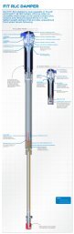
Air Sleeve Maintenance See www.foxracingshox.com for downloadable video instructions.Release all air pressure from Air Valve.Cycle shock a few times to release pressure from the air negative spring.Release all air pressure from Air Valve again.Remove shock from bikeRemove aluminum reducers.Clamp shaft eyelet in a vise with soft jaws being careful not to crush the air valve, lock out lever, or rebound knob.Slide a screwdriver or punch through the body eyelet to keep the air sleeve from coming off the body.Loosen air sleeve by turning counter clockwise and slide it down the body.Remove screwdriver or punch.DAMPERASSEMBLYGREASE LIBERALLYTHREADS FOR AIR SLEEVEREDUCERSHAFTREDUCERSHAFT EYELETBODY EYELETSHOCK BODYBODY BEARINGBODY SEALBODY BEARINGGREASE LIGHTLYAIR VALVESHAFT EYELET O-RINGGREASE BEARINGS, SEAL, & WIPERAIR SLEEVE WIPERAIR SLEEVE BEARINGAIR SLEEVE BEARINGAIR SLEEVE SEALCleaning and InspectingClean inside of the air sleeve with parts cleaner.Inspect the seal and bearing inside of the air sleeve.Replace if damaged or worn.Clean body, body seal, body bearings and shaft with parts cleaner.Inspect body seal and body bearings for wear or damage.Replace if damaged or worn.Greasing and ReassemblingLightly lube the shaft eyelet O-ring and shaft eyelet threads with FLOAT Fluid or Multi-purpose Lithium based grease(NLGI #2).Liberally lube the body seal and body bearing, leaving a reservoir of lube above the body bearing .Lightly grease the air sleeve seal, air sleeve bearing, and air sleeve wiper.Slide the air sleeve over the body until the air sleeve wiper is at the end of the body. Leave the air sleeve unthreadedat this time.(The air sleeve will be very difficult to compress because there is pressure trapped in the air negative chamber.Waiting until after the shock is mounted in the bike will allow the leverage of the bike to easily compress the shock.)Dry bushings and reducers.Install reducers in eyelet bushings.Install shock in bike.Carefully compress shock until you can screw on the air sleeve. Do not let the air sleeve slip off the body.Thread air sleeve onto shaft eyelet.Inflate shock using inflation instructions listed in the Pump Instructions.Note: If needed, the Air Sleeve Seal Kit part number is 803-00-050-B.FLOAT Fluid part numbers: 025-03-002-A 5 cc Pillow Pack12025-03-003-A 8 oz. Bottle
Specialized Epic BRAINYour Specialized bicycle features a FOX Racing Shox FLOAT R with BRAIN Technology. This technology sensesbumps in the trail and activates the suspension as necessary giving the rider the efficiency of a hardtail with all thebenefits of a full suspension bicycle.To optimize the performance of the shock, it is important to set it up correctly. Taking the time to tune the spring rate(air pressure) and rebound damping (rate at which the shock returns) will greatly enhance the riding experience.Because the shock defaults to a locked out position, the shock cannot be set up using the traditional method forsetting sag. For this reason we recommend that the initial set up be done according to the air spring chart below.Find your weight range on the chart below and set the air pressure to the corresponding value. Take a shock pumpalong on the next ride and monitor the performance of the shock. Slide the travel indicator o-ring up against thescraper lip before starting to ride. This will help show how much travel is being used. If the shock seems to bottomexcessively, increase the air pressure by five (5) psi. If the shock seems too stiff or if full travel is not achievable,decrease the air pressure by five (5) psi. The goal is to use the full travel of the shock once or twice on each ride. Fullshock travel is 1 7/8 inches +/- 1/8 in (48 millimeters +/- 3 mm). Much of this depends on the terrain and one’s ridingstyle so take these into consideration during the set up process.Rebound damping controls the rate at which the shock returns after it has been compressed. The red adjuster dialcan be turned clockwise for slower rebound and counter-clockwise for faster rebound. There is a wide range ofadjustment enabling the rider to tune the shock to any air pressure and riding condition. The proper rebound settingis a personal preference and varies depending on rider weight, riding style and riding conditions. As a general rule,rebound should be as fast as possible without kicking back and pushing the rider off the saddle when riding thebicycle in rough terrain. If rebound is too slow the suspension will not function properly and the wheel will not followthe changing terrain. Determining the proper rebound setting may take a number of rides. Use the “curb test” to startdialing in your rebound setting. Do this test on flat ground where there is little auto traffic and plenty of room. Ride atnormal cruising speed and stay seated. Ride off a curb and monitor the rebound. If the bike oscillates a few timesafter landing the rebound is too fast. If the shock does not return promptly it is too slow. Start with the dial in themiddle (about 12 clicks from full slow) and adjust 4 clicks in the direction needed. Single clicks of adjustment can beused to fine tune the rebound damping. During the first few rides, adjust the rebound damping and note the differentride characteristics. Your rebound damping setting may change with different riding conditions.Air sleeve service can be performed as on other FOX Racing Shox FLOAT rear shocks (see pages 10&11 for details).The strut must be removed before removing the air sleeve. A 22mm open end wrench is required to remove the strut.Torque to 175-200 in-lb (19.5-22.5 N-m) when reinstalling. A 22mm crowfoot attachment and a torque wrench arerequired to install the strut.Note: Excepting air sleeve service, all repairs and warranty issues must be handled by Specialized BicycleCompany. All repairs and service for BRAIN technology shocks will be provided through an AuthorizedSpecialized Dealer in your country. Please contact your local Specialized dealer for repair and warrantyissues.BRAIN Air Spring ChartRider Weight Air PressureLbs. (Kg.) Psi90 - 100 (34-37) 60 - 65100-110 (37-41) 65 - 70110-120 (41-45) 70 - 75120-130 (45-49) 75 - 80130-140 (49-52) 80 - 85140-150 (52-56) 85 - 90150-160 (56-60) 90 - 100160-170 (60-63) 100 -110170-180 (63-67) 110 - 120180-190 (67-71) 120 - 130190-200 (71-75) 130 - 140200-210 (75-78) 140 - 150210-220 (78-82) 150 - 160220-230 (82-86) 160 - 170230-240 (86-90) 170 - 180240-250 (90-93) 180 - 190250-265 (93-99) 190 - 200265-280 (99-105) 200 - 215280-295 (105-110) 215 - 230Travel IndicatorO-ringSchrader ValveRebound Adjuster Dial13
Remote Lock-Out InstructionsClean eyelet and air sleeve with degreaser.Set shock lock-out to locked-out position. Fig. 2Remove lever with a 5/64 (or 2mm) hex key.DO NOT REMOVE CAM. DO NOT LOOSENSET SCREWS.Place adapter plate on the eyelet and overthe cam (M.Y. 2000 & 2001 only). Fig. 1New Remote LeverTorsion SpringAdapter PlateCamFig. 1 Adapter Plate, Spring and Lever InstallationInsert torsion spring in corresponding hole on plate or eyelet. Fig. 1Position new remote lever over cam onto torsion spring arm. Fig. 1Rotate remote lever counter-clockwise to preload the spring and align the flat. Tighten set screw onto the flat of thecam. Fig. 3Attach cable stop collar onto air sleeve flange. Orient cable stop just off center. (Fig. 3) Overtightening the collar cancrush the air sleeve. Tighten collar only until it is secure and does not rotate on air sleeve.Let air out of shock and cycle to full bottom out. Check clearances of all parts in compressed and extended positions.Cut cable and housing to length. Use only derailleur cable and housing. (1.1mm stainless cable is recommended)Run cable around radius on remote lever and through the hole. Push cable through housing and route along frameto cable stop collar and around remote lockout lever. Apply tension on cable and tighten set screw to hold the cable -DO NOT OVERTIGHTEN. Fig. 3CompressionDampingClosedAdjust cable tension with the barrel+/-45 o Leversadjuster at handlebar mounted lever.EyeletCompressionDampingClosedCompressionDampingOpenCompressionDamping OpenAir Sleeve1/8”-5/16”3.0mm-8.0mmCable Stop Collar0 o / 180 oLeversRemote Lock-Out Lever Installation InstructionsThe remote lock-out lever can be installed above or below the handlebar on either the left or right side. The levercomes pre-assemled to be mounted on top of the handlebar on the right side.To re-orient the lever, remove the lever assembly from the clamp assembly with a 2mm (or 5/64) hex wrench.Mount clamp assembly in desired location and re-mount lever assembly.DO NOT OVERTIGHTEN mounting screws.To adjust lever friction, use a 3mm hex wrench to tighten or loosen the button head screw in the middle of the leverhousing. Use an 8mm (or 5/16) socket to hold the nut on the bottom of the lever housing.14
RVanilla <strong>Shock</strong>sTo get the best performance from your Vanilla shock, it is necessary to adjust sag. On the coil-over shocks this is doneby adjusting the spring preload or changing springs. Sag is how much the shock compresses when you sit on the bicycle.Increasing spring preload will make the shock compress less. Decreasing the preload will make the shock compressmore. The smoothest ride will be achieved with one turn of preload. (Note: it might be necessary to change spring rateto achieve the proper sag setting.) Adjusting sag setting is easiest with two people, the bike rider and an assistant.Adjusting Sag<strong>Shock</strong>TravelVanilla Sag TableRecommended SagIf more than 2 turns of preload are required to achievethe correct amount of sag, it is recommended that ahigher rate spring be installed.( inches) ( millimeters ) ( inches)(millimeters )1.001.251.501.752.002.252.502.7525.431.738.144.450.857.163.569.9.25.31.38.44.50.56.63.696.47.99.511.112.714.315.917.5To set the preload, you need to adjust the spring preload ring. FOX Racing Shox recommends no more than 2 turns ofpreload. Adjust preload by turning the preload ring onto the body. Clockwise turns increase preload, which decreasesthe sag. Counterclockwise turns decrease preload, which increases sag.If desired preload cannot be achieved with the preload ring, change the spring (See Installing and Removing Springs).A stiffer spring (higher spring rate) decreases sag. A softer spring (lower spring rate) increases sag.Springs are available from FOX Racing Shox as well as authorized dealers and service centers. Numbers areprinted on the outside of the spring coils indicating the rate (in pounds) and travel (in inches). Example: 550-1.95 is a550 pound-per-inch spring rate with 1.95 inches of travel. Please note this number when ordering replacement springs.Also be prepared with the make, model, and year of bicycle, shock travel, rider weight and riding style.Installing and Removing SpringsTo remove the spring from your shock, follow these steps:Vanilla, Vanilla R & Vanilla RLLoosen and remove the preload ring from the body.Note: It might be necessary to remove the reducers fromthe body end of the shock to remove the spring.Slide the spring over the shock body.Install your new spring by sliding the spring over theshock body.Tighten the preload adjuster one full turn to keep thepreload ring from shaking loose.SLOWESPRING(SLIDE OVER BODY)BODYREDUCERREDUCERPRELOAD RING(REMOVE FROM BODY)SLOTTED REDUCERVanilla RCSPRINGRETAINERBack off preload ring to loosen the spring until theslotted spring retainer can be removed from the shock.Note: It might be necessary to remove the reducers fromthe shaft end of the shock to remove the spring.Slide the spring over the eyelet.Slide the new spring on over the eyelet, and re-install thespring retainer.SHAFT EYELETNote: The slotted spring ring retainer slot must rest onREDUCERthe flat side of the spring. If the slot is straddling the gapcaused by the end of the spring wire the slotted springretainer may bend.Tighten the preload adjuster one full turn to keep thespring retainer from shaking loose.Align the slotted spring retainer so that the reboundknob is in the middle of the slot.S LOWERSPRING (SLIDE OVER SHAFT EYELET)PRELOAD RING(LOOSEN TO REMOVE SPRING)HARDE R15
Vanilla<strong>Shock</strong> FeaturesAdjustable Spring Preload - External Coil Spring - Internal Floating Piston - Oil DampingOne Piece Aluminum Body - One Piece Eyelet - Nitrogen Charged - Speed Sensitive Compression DampingVanilla R<strong>Shock</strong> FeaturesAdjustable Spring Preload - External Coil Spring - Internal Floating Piston - Oil DampingOne Piece Aluminum Body - One Piece Eyelet - Nitrogen Charged - Speed Sensitive Compression DampingMulti-Valve Piston - 12 Click Externally Adjustable Rebound Damping - Speed Sensitive Rebound Valve StackREBOUND ADJUSTERKNOB (RED)Rebound AdjustmentRebound damping controls the rate at which the shock returns after it has been compressed. The red adjuster dialcan be turned clockwise for slower rebound and counter-clockwise for faster rebound. There is a wide range ofadjustment enabling the rider to tune the shock to any air pressure and riding condition. The proper rebound settingis a personal preference and varies depending on rider weight, riding style and riding conditions. As a general rule,rebound should be as fast as possible without kicking back and pushing the rider off the saddle when riding thebicycle in rough terrain. If rebound is too slow the suspension will not function properly and the wheel will not followthe changing terrain. Determining the proper rebound setting may take a number of rides. Use the “curb test” to startdialing in your rebound setting. Do this test on flat ground where there is little auto traffic and plenty of room. Ride atnormal cruising speed and stay seated. Ride off a curb and monitor the rebound. If the bike oscillates a few timesafter landing the rebound is too fast. If the shock does not return promptly it is too slow. Start with the dial in themiddle (about 12 clicks from full slow) and adjust 4 clicks in the direction needed. Single clicks of adjustment can beused to fine tune the rebound damping. During the first few rides, adjust the rebound damping and note the differentride characteristics. Your rebound damping setting may change with different riding conditions.16
Vanilla RL<strong>Shock</strong> FeaturesAdjustable Spring Preload - External Coil Spring - Internal Floating Piston - Oil DampingOne Piece Aluminum Body - One Piece Eyelet - Nitrogen Charged - Speed Sensitive Compression DampingMulti-Valve Piston - 12 Click Externally Adjustable Rebound Damping - Speed Sensitive Rebound Valve StackCompression Lock-out with High Speed Blow-offRebound AdjustmentPlease refer to Rebound Adjustment for Vanilla R.Compression Lock-outCompression lock-out is featured on the Vanilla RL <strong>Shock</strong>. The compression lock-out is the blue lever. There are threeoptions for lever position for the Vanilla RL. For one option, the lever is at a 45° angle counter clockwise to the shock in thenormal position. Moving the lever clockwise 90° increases compression damping which “locks-out” the shock. On anotheroption, the lever is in line with the shock in the normal position. Moving the lever 180° in either direction increases compressiondamping. On the third option, the lever is in line with the shock in the normal position. Move the lever 90° clockwise toincrease compression damping. The increased compression damping setting will be firm but will “blow off” under a big hitor heavy load.Vanilla RC<strong>Shock</strong> FeaturesAdjustable Spring Preload - External Coil Spring - Internal Floating Piston - Oil DampingOne Piece Aluminum Body - One Piece Eyelet - Nitrogen Charged - Speed Sensitive Compression DampingMulti-Valve Piston - 12 Click Externally Adjustable Rebound Damping - Speed Sensitive Rebound Valve StackPiggy Back Remote Reservoir - 12 Click Externally Adjustable Compression DampingRebound AdjustmentPlease refer to Rebound Adjustment for Vanilla R.Compression DampingCompression damping on the Vanilla RC is adjusted by turning the blue knob. To make the shock harder to compress,turn the knob clockwise. Turn the knob counter-clockwise for easier compression. Adjust the compression on the first fewrides and note the different characteristics. Your settings may change with different conditions. The smoothest ride will beattained with the compression adjuster in the softest setting.17
M-BITS by FOX Racing ShoxYour bicycle features M-BITS by FOX Racing Shox as part of the rear suspension system.To optimize the performance of the shock, it is important to set it up correctly. Taking the time to tune the spring rate(air pressure) and rebound damping (rate at which the shock returns) will greatly enhance the riding experience.Air pressure is increased or decreased by attaching a shock pump to the schrader valve on the left side (from rider’sperspective) of the shock body. Please reference the chart below to set the air pressure. These air pressures areprovided as a guide and should be used as a starting point. Make incremental adjustments to air pressure on thefirst few rides and monitor how the ride characteristics change. This will help determine your optimal air pressure.With the air pressure properly set, the shock should compress about 17-20mm when the rider sits on the bicycle in anormal riding position. This is called sag. If the shock sags too much, increase the air pressure slightly. If the shockdoesn’t sag enough, slightly decrease the air pressure.The air pressure range for the shock is 5 to 60psi for most riders. If significantly more pressure is required to achieveproper sag, please contact your bicycle manufacturer or FOX Racing Shox.Rider WeightLbs. (Kg.)Air PressurePSI< 100 (45)25120(55)30140(65)35160(75)40Alternate Methods: Divide rider’s weight in pounds by 4 to determine PSI orrider’s weight in kilograms by 27 to determine bar.Example: 160lb. rider - 160/4 = 40 psi81kg rider - 81/27 = 3.0 bar180(85)45200+ (90+) 50-60Use the knob on the left side (from rider’s perspective) of the shock to adjust the rebound damping. Refer to the chartbelow to find the setting recommended relative to your air pressure.The proper rebound setting is a personal preference and varies depending on rider weight, riding style and ridingconditions. As a general rule, rebound should be as fast as possible without kicking back and pushing the rider offthe saddle when riding the bicycle in rough terrain. If rebound is too slow the suspension will not function properlyand the wheel will not follow the changing terrain. Determining the proper rebound setting may take a number ofrides. Use the “curb test” to start dialing in your rebound setting. Do this test on flat ground where there is little autotraffic and plenty of room. Ride at normal cruising speed and stay seated. Ride off a curb and monitor the rebound. Ifthe bike oscillates a few times after landing the rebound is too fast. If the shock does not return promptly it is tooslow. During the first few rides, adjust the rebound damping and note the different ride characteristics. Your rebounddamping setting may change with different riding conditions.PSIBarAdjusterNumber< 10 < 1. 0110-201.0-1.5 220-301.5-2.0 330-402.0-2.5 440-502.5-3.0 550+3.0+6605-00-020-A 2002 FOX Racing Shox. <strong>Rear</strong> <strong>Shock</strong> Owner’s <strong>Manual</strong>. The information herein is provided as a guide.FOX Racing Shox reserves the right to change all or part without notice.18