Apricus Solar Water Heating System Installation and Operation ...
Apricus Solar Water Heating System Installation and Operation ...
Apricus Solar Water Heating System Installation and Operation ...

Create successful ePaper yourself
Turn your PDF publications into a flip-book with our unique Google optimized e-Paper software.
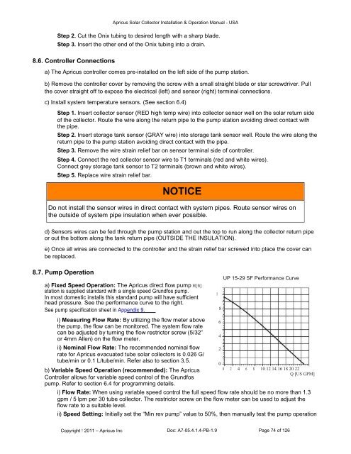
<strong>Apricus</strong> <strong>Solar</strong> Collector <strong>Installation</strong> & <strong>Operation</strong> Manual - USAStep 2. Cut the Onix tubing to desired length with a sharp blade.Step 3. Insert the other end of the Onix tubing into a drain.8.6. Controller Connectionsa) The <strong>Apricus</strong> controller comes pre-installed on the left side of the pump station.b) Remove the controller cover by removing the screw with a small straight blade or star screwdriver. Pullthe cover straight off to expose the electrical (left) <strong>and</strong> sensor (right) terminal connections.c) Install system temperature sensors. (See section 6.4)Step 1. Insert collector sensor (RED high temp wire) into collector sensor well on the solar return sideof the collector. Route the wire along the return pipe to the pump station avoiding direct contact withthe pipe.Step 2. Insert storage tank sensor (GRAY wire) into storage tank sensor well. Route the wire along thereturn pipe to the pump station avoiding direct contact with the pipe.Step 3. Remove the wire strain relief bar on sensor terminal side of controller.Step 4. Connect the red collector sensor wire to T1 terminals (red <strong>and</strong> white wires).Connect grey storage tank sensor to T2 terminals (brown <strong>and</strong> white wires).Step 5. Replace wire strain relief bar.NOTICEDo not install the sensor wires in direct contact with system pipes. Route sensor wires onthe outside of system pipe insulation when ever possible.d) Sensors wires can be fed through the pump station <strong>and</strong> out the top to run along the collector return pipeor out the bottom along the tank return pipe (OUTSIDE THE INSULATION).e) Once all wires are connected to the controller <strong>and</strong> the strain relief bar screwed into place the cover canbe replaced.8.7. Pump <strong>Operation</strong>a) Fixed Speed <strong>Operation</strong>: The <strong>Apricus</strong> direct flow pump H[ft]station is supplied st<strong>and</strong>ard with a single speed Grundfos pump.In most domestic installs this st<strong>and</strong>ard pump will have sufficienthead pressure. See the performance curve to the right.See pump specification sheet in Appendix 9.i) Measuring Flow Rate: By utilizing the flow meter abovethe pump, the flow can be monitored. The system flow ratecan be adjusted by turning the flow restrictor screw (5/32”or 4mm Allen) on the flow meter.ii) Nominal Flow Rate: The recommended nominal flowrate for <strong>Apricus</strong> evacuated tube solar collectors is 0.026 G/tube/min or 0.1 L/tube/min. Refer also to section 3.5.b) Variable Speed <strong>Operation</strong> (recommended): The <strong>Apricus</strong>Controller allows for variable speed control of the Grundfospump. Refer to section 6.4 for programming details.1086420UP 15-29 SF Performance Curve0 2 4 6 8 10 12 14 16 18 20 22Q [US GPM]i) Flow Rate: When using variable speed control the full speed flow rate should be no more than 1.3gpm / 5 lpm per 30 tube collector. The restrictor screw on the flow meter can be used to adjust theflow rate to a suitable level.ii) Speed Setting: Initially set the “Min rev pump” value to 50%, then manually test the pump operationCopyright 2011 – <strong>Apricus</strong> Inc Doc: A7-05.4.1.4-PB-1.9 Page 74 of 126