2. installation procedure for optional equipment - toshiba tec europe
2. installation procedure for optional equipment - toshiba tec europe 2. installation procedure for optional equipment - toshiba tec europe
2. INSTALLATION PROCEDURE FOR OPTIONAL EQUIPMENT EO18-120102.3 Installing the Line Display, Pole Unit, and VFD Stand• Installation Procedure (when installing the Line Display with the Pole Unit and the VFD Stand)1) Remove the Rear Cover. (Refer to Section 2.1 Installing the Hard Disk Drive (HDD).)2) Remove the two Hinge Holders from the Rear Cover. (Refer to Section 2.2 Installing the LVDS PC Boardand Back Indicator Unit.)3) Remove the Front Cover and Side Cover (L). (Refer to Section 2.2 Installing the LVDS PC Board andBack Indicator Unit.)4) Attach the POLE-S (F) and the POLE-S (R) onto the axis of the Line Display so that the Nut of the POLE-S(R) faces back.NOTE: Before placing the Line Display so that the front side faces down, set a soft cloth on a table. Failureto do this may cause the display to get scratched.POLE-S (F) POLE-S (R) Nut5) Disconnect the shorter VFD Cable which is provided for the Line Display as standard, then connect the VFDExtension Cable to the longer VFD Cable.VFD Extension Cable6) Attach the POLE-L (F) and the POLE-L (R), then secure them with the screw.T-3x16 ScrewPOLE-L (R)POLE-L (F)2-14
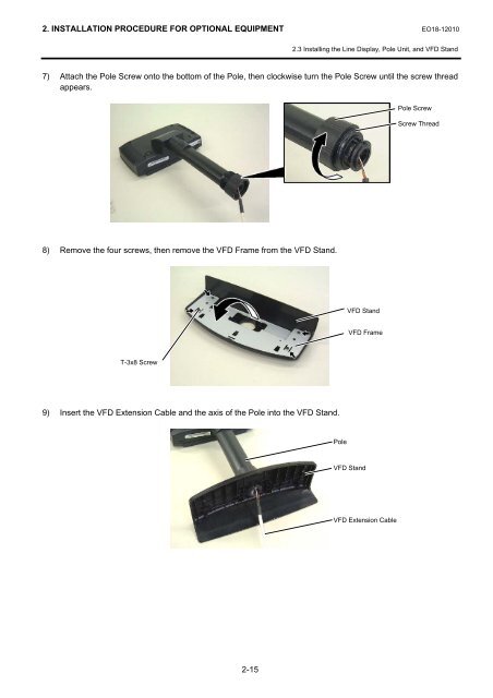
2. INSTALLATION PROCEDURE FOR OPTIONAL EQUIPMENT EO18-120102.3 Installing the Line Display, Pole Unit, and VFD Stand7) Attach the Pole Screw onto the bottom of the Pole, then clockwise turn the Pole Screw until the screw threadappears.Pole ScrewScrew Thread8) Remove the four screws, then remove the VFD Frame from the VFD Stand.VFD StandVFD FrameT-3x8 Screw9) Insert the VFD Extension Cable and the axis of the Pole into the VFD Stand.PoleVFD StandVFD Extension Cable2-15
- Page 1 and 2: TEC POS TerminalST-71 SERIESMainten
- Page 3 and 4: EO18-12010(Revision Date: Jan. 30,
- Page 5 and 6: 1. UNPACKING EO18-120101.1 Procedur
- Page 7 and 8: 2. INSTALLATION PROCEDURE FOR OPTIO
- Page 9 and 10: 2. INSTALLATION PROCEDURE FOR OPTIO
- Page 11 and 12: 2. INSTALLATION PROCEDURE FOR OPTIO
- Page 13 and 14: 2. INSTALLATION PROCEDURE FOR OPTIO
- Page 15 and 16: 2. INSTALLATION PROCEDURE FOR OPTIO
- Page 17 and 18: 2. INSTALLATION PROCEDURE FOR OPTIO
- Page 19: 2. INSTALLATION PROCEDURE FOR OPTIO
- Page 23 and 24: 2. INSTALLATION PROCEDURE FOR OPTIO
<strong>2.</strong> INSTALLATION PROCEDURE FOR OPTIONAL EQUIPMENT EO18-12010<strong>2.</strong>3 Installing the Line Display, Pole Unit, and VFD Stand7) Attach the Pole Screw onto the bottom of the Pole, then clockwise turn the Pole Screw until the screw threadappears.Pole ScrewScrew Thread8) Remove the four screws, then remove the VFD Frame from the VFD Stand.VFD StandVFD FrameT-3x8 Screw9) Insert the VFD Extension Cable and the axis of the Pole into the VFD Stand.PoleVFD StandVFD Extension Cable2-15


