2. installation procedure for optional equipment - toshiba tec europe
2. installation procedure for optional equipment - toshiba tec europe
2. installation procedure for optional equipment - toshiba tec europe
- No tags were found...

Create successful ePaper yourself
Turn your PDF publications into a flip-book with our unique Google optimized e-Paper software.
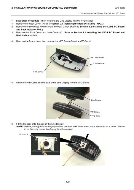
<strong>2.</strong> INSTALLATION PROCEDURE FOR OPTIONAL EQUIPMENT EO18-12010<strong>2.</strong>3 Installing the Line Display, Pole Unit, and VFD Stand• Installation Procedure (when installing the Line Display with the VFD Stand)1) Remove the Rear Cover. (Refer to Section <strong>2.</strong>1 Installing the Hard Disk Drive (HDD).)2) Remove the two Hinge Holders from the Rear Cover. (Refer to Section <strong>2.</strong>2 Installing the LVDS PC Boardand Back Indicator Unit.)3) Remove the Front Cover and Side Cover (L). (Refer to Section <strong>2.</strong>2 Installing the LVDS PC Board andBack Indicator Unit.)4) Remove the four screws, then remove the VFD Frame from the VFD Stand.VFD StandVFD FrameT-3x8 Screw5) Insert the VFD Cable and the axis of the Line Display into the VFD Stand.Line DisplayVFD CableVFD Stand6) Fit the Stopper onto the axis of the Line Display.NOTE: Be<strong>for</strong>e placing the Line Display so that the front side faces down, set a soft cloth on a table. Failureto do this may cause the display to get scratched.Stopper2-11