2. installation procedure for optional equipment - toshiba tec europe
2. installation procedure for optional equipment - toshiba tec europe 2. installation procedure for optional equipment - toshiba tec europe
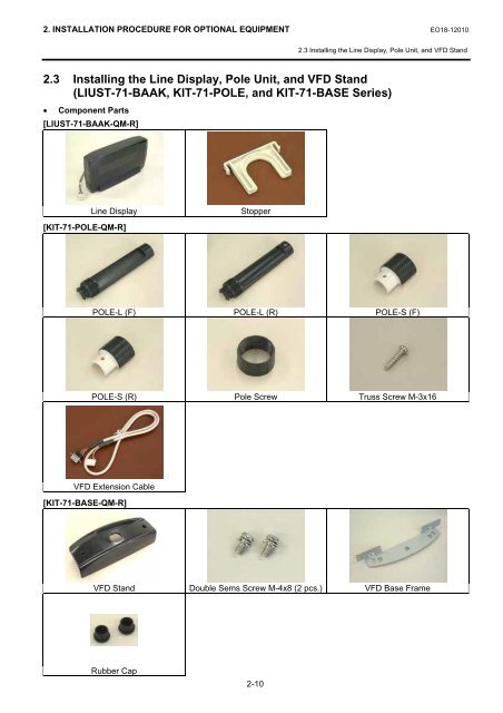
2. INSTALLATION PROCEDURE FOR OPTIONAL EQUIPMENT EO18-120102.3 Installing the Line Display, Pole Unit, and VFD Stand2.3 Installing the Line Display, Pole Unit, and VFD Stand(LIUST-71-BAAK, KIT-71-POLE, and KIT-71-BASE Series)• Component Parts[LIUST-71-BAAK-QM-R]Line Display[KIT-71-POLE-QM-R]StopperPOLE-L (F) POLE-L (R) POLE-S (F)POLE-S (R) Pole Screw Truss Screw M-3x16VFD Extension Cable[KIT-71-BASE-QM-R]VFD Stand Double Sems Screw M-4x8 (2 pcs.) VFD Base FrameRubber Cap2-10
2. INSTALLATION PROCEDURE FOR OPTIONAL EQUIPMENT EO18-120102.3 Installing the Line Display, Pole Unit, and VFD Stand• Installation Procedure (when installing the Line Display with the VFD Stand)1) Remove the Rear Cover. (Refer to Section 2.1 Installing the Hard Disk Drive (HDD).)2) Remove the two Hinge Holders from the Rear Cover. (Refer to Section 2.2 Installing the LVDS PC Boardand Back Indicator Unit.)3) Remove the Front Cover and Side Cover (L). (Refer to Section 2.2 Installing the LVDS PC Board andBack Indicator Unit.)4) Remove the four screws, then remove the VFD Frame from the VFD Stand.VFD StandVFD FrameT-3x8 Screw5) Insert the VFD Cable and the axis of the Line Display into the VFD Stand.Line DisplayVFD CableVFD Stand6) Fit the Stopper onto the axis of the Line Display.NOTE: Before placing the Line Display so that the front side faces down, set a soft cloth on a table. Failureto do this may cause the display to get scratched.Stopper2-11
- Page 1 and 2: TEC POS TerminalST-71 SERIESMainten
- Page 3 and 4: EO18-12010(Revision Date: Jan. 30,
- Page 5 and 6: 1. UNPACKING EO18-120101.1 Procedur
- Page 7 and 8: 2. INSTALLATION PROCEDURE FOR OPTIO
- Page 9 and 10: 2. INSTALLATION PROCEDURE FOR OPTIO
- Page 11 and 12: 2. INSTALLATION PROCEDURE FOR OPTIO
- Page 13 and 14: 2. INSTALLATION PROCEDURE FOR OPTIO
- Page 15: 2. INSTALLATION PROCEDURE FOR OPTIO
- Page 19 and 20: 2. INSTALLATION PROCEDURE FOR OPTIO
- Page 21 and 22: 2. INSTALLATION PROCEDURE FOR OPTIO
- Page 23 and 24: 2. INSTALLATION PROCEDURE FOR OPTIO
<strong>2.</strong> INSTALLATION PROCEDURE FOR OPTIONAL EQUIPMENT EO18-12010<strong>2.</strong>3 Installing the Line Display, Pole Unit, and VFD Stand<strong>2.</strong>3 Installing the Line Display, Pole Unit, and VFD Stand(LIUST-71-BAAK, KIT-71-POLE, and KIT-71-BASE Series)• Component Parts[LIUST-71-BAAK-QM-R]Line Display[KIT-71-POLE-QM-R]StopperPOLE-L (F) POLE-L (R) POLE-S (F)POLE-S (R) Pole Screw Truss Screw M-3x16VFD Extension Cable[KIT-71-BASE-QM-R]VFD Stand Double Sems Screw M-4x8 (2 pcs.) VFD Base FrameRubber Cap2-10


