2. installation procedure for optional equipment - toshiba tec europe
2. installation procedure for optional equipment - toshiba tec europe
2. installation procedure for optional equipment - toshiba tec europe
- No tags were found...

You also want an ePaper? Increase the reach of your titles
YUMPU automatically turns print PDFs into web optimized ePapers that Google loves.
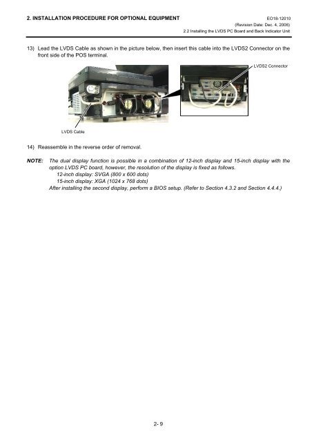
<strong>2.</strong> INSTALLATION PROCEDURE FOR OPTIONAL EQUIPMENT EO18-12010(Revision Date: Dec. 4, 2006)<strong>2.</strong>2 Installing the LVDS PC Board and Back Indicator Unit13) Lead the LVDS Cable as shown in the picture below, then insert this cable into the LVDS2 Connector on thefront side of the POS terminal.LVDS2 ConnectorLVDS Cable14) Reassemble in the reverse order of removal.NOTE:The dual display function is possible in a combination of 12-inch display and 15-inch display with theoption LVDS PC board, however, the resolution of the display is fixed as follows.12-inch display: SVGA (800 x 600 dots)15-inch display: XGA (1024 x 768 dots)After installing the second display, per<strong>for</strong>m a BIOS setup. (Refer to Section 4.3.2 and Section 4.4.4.)2- 9