Dräger Polytron IR type 334 and type 340 - ancb.it
Dräger Polytron IR type 334 and type 340 - ancb.it
Dräger Polytron IR type 334 and type 340 - ancb.it

You also want an ePaper? Increase the reach of your titles
YUMPU automatically turns print PDFs into web optimized ePapers that Google loves.
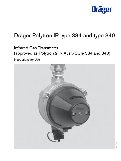
D<strong>Dräger</strong> <strong>Polytron</strong> <strong>IR</strong> <strong>type</strong> <strong>334</strong> <strong>and</strong> <strong>type</strong> <strong>340</strong>Infrared Gas Transm<strong>it</strong>ter(approved as <strong>Polytron</strong> 2 <strong>IR</strong> Ausf./Style <strong>334</strong> <strong>and</strong> <strong>340</strong>)Instructions for UseST–3836–2003.eps
ContentsContentsFor Your Safety . . . . . . . . . . . . . . . . . . . . . . . . . . . . . . . . . . . . . . . . . . . . . . . . . . . . . . . . . . . . . . . . . . . . . . . . . . . . . . . . . . . . . . . . . . . . . . 4Intended use . . . . . . . . . . . . . . . . . . . . . . . . . . . . . . . . . . . . . . . . . . . . . . . . . . . . . . . . . . . . . . . . . . . . . . . . . . . . . . . . . . . . . . . . . . . . . . . . 5Approval for use in hazardous areas . . . . . . . . . . . . . . . . . . . . . . . . . . . . . . . . . . . . . . . . . . . . . . . . . . . . . . . . . . . . . . . . . . . . . . . . . . . 5Installation of the gas transm<strong>it</strong>ter . . . . . . . . . . . . . . . . . . . . . . . . . . . . . . . . . . . . . . . . . . . . . . . . . . . . . . . . . . . . . . . . . . . . . . . . . . . . . 6Installation s<strong>it</strong>e . . . . . . . . . . . . . . . . . . . . . . . . . . . . . . . . . . . . . . . . . . . . . . . . . . . . . . . . . . . . . . . . . . . . . . . . . . . . . . . . . . . . . . . . . . . . . . . . 6Mechanical installation . . . . . . . . . . . . . . . . . . . . . . . . . . . . . . . . . . . . . . . . . . . . . . . . . . . . . . . . . . . . . . . . . . . . . . . . . . . . . . . . . . . . . . . . . 7Electrical installation . . . . . . . . . . . . . . . . . . . . . . . . . . . . . . . . . . . . . . . . . . . . . . . . . . . . . . . . . . . . . . . . . . . . . . . . . . . . . . . . . . . . . . . . . . . 8Installation of the accessories . . . . . . . . . . . . . . . . . . . . . . . . . . . . . . . . . . . . . . . . . . . . . . . . . . . . . . . . . . . . . . . . . . . . . . . . . . . . . . . . . . 10Operation . . . . . . . . . . . . . . . . . . . . . . . . . . . . . . . . . . . . . . . . . . . . . . . . . . . . . . . . . . . . . . . . . . . . . . . . . . . . . . . . . . . . . . . . . . . . . . . . . . 13System start-up . . . . . . . . . . . . . . . . . . . . . . . . . . . . . . . . . . . . . . . . . . . . . . . . . . . . . . . . . . . . . . . . . . . . . . . . . . . . . . . . . . . . . . . . . . . . . . . 13Configuring the gas transm<strong>it</strong>ter . . . . . . . . . . . . . . . . . . . . . . . . . . . . . . . . . . . . . . . . . . . . . . . . . . . . . . . . . . . . . . . . . . . . . . . . . . . . . . . . . 14Measurement . . . . . . . . . . . . . . . . . . . . . . . . . . . . . . . . . . . . . . . . . . . . . . . . . . . . . . . . . . . . . . . . . . . . . . . . . . . . . . . . . . . . . . . . . . . . . . . . 16Maintenance . . . . . . . . . . . . . . . . . . . . . . . . . . . . . . . . . . . . . . . . . . . . . . . . . . . . . . . . . . . . . . . . . . . . . . . . . . . . . . . . . . . . . . . . . . . . . . . 17Maintenance intervals . . . . . . . . . . . . . . . . . . . . . . . . . . . . . . . . . . . . . . . . . . . . . . . . . . . . . . . . . . . . . . . . . . . . . . . . . . . . . . . . . . . . . . . . . 17Checking <strong>and</strong> if necessary cleaning the cuvette in the gas transm<strong>it</strong>ter . . . . . . . . . . . . . . . . . . . . . . . . . . . . . . . . . . . . . . . . . . . . . . . . 18Fault, cause, remedy . . . . . . . . . . . . . . . . . . . . . . . . . . . . . . . . . . . . . . . . . . . . . . . . . . . . . . . . . . . . . . . . . . . . . . . . . . . . . . . . . . . . . . . . 19Method of operation . . . . . . . . . . . . . . . . . . . . . . . . . . . . . . . . . . . . . . . . . . . . . . . . . . . . . . . . . . . . . . . . . . . . . . . . . . . . . . . . . . . . . . . . 20Connecting the h<strong>and</strong> terminal ABB 691 HT . . . . . . . . . . . . . . . . . . . . . . . . . . . . . . . . . . . . . . . . . . . . . . . . . . . . . . . . . . . . . . . . . . . . . . 20Sw<strong>it</strong>ching on the h<strong>and</strong> terminal . . . . . . . . . . . . . . . . . . . . . . . . . . . . . . . . . . . . . . . . . . . . . . . . . . . . . . . . . . . . . . . . . . . . . . . . . . . . . . . . . 20Sw<strong>it</strong>ching off the h<strong>and</strong> terminal . . . . . . . . . . . . . . . . . . . . . . . . . . . . . . . . . . . . . . . . . . . . . . . . . . . . . . . . . . . . . . . . . . . . . . . . . . . . . . . . . 20Linking up w<strong>it</strong>h the gas transm<strong>it</strong>ter . . . . . . . . . . . . . . . . . . . . . . . . . . . . . . . . . . . . . . . . . . . . . . . . . . . . . . . . . . . . . . . . . . . . . . . . . . . . . . 21Menu structure . . . . . . . . . . . . . . . . . . . . . . . . . . . . . . . . . . . . . . . . . . . . . . . . . . . . . . . . . . . . . . . . . . . . . . . . . . . . . . . . . . . . . . . . . . . . . . . 21"PV" menu (Dynamic Var) . . . . . . . . . . . . . . . . . . . . . . . . . . . . . . . . . . . . . . . . . . . . . . . . . . . . . . . . . . . . . . . . . . . . . . . . . . . . . . . . . . . . 23MEASUREMENT TYPE . . . . . . . . . . . . . . . . . . . . . . . . . . . . . . . . . . . . . . . . . . . . . . . . . . . . . . . . . . . . . . . . . . . . . . . . . . . . . . . . . . . . . . . 23ON LINE INFO . . . . . . . . . . . . . . . . . . . . . . . . . . . . . . . . . . . . . . . . . . . . . . . . . . . . . . . . . . . . . . . . . . . . . . . . . . . . . . . . . . . . . . . . . . . . . . . 23"REVIEW" menu . . . . . . . . . . . . . . . . . . . . . . . . . . . . . . . . . . . . . . . . . . . . . . . . . . . . . . . . . . . . . . . . . . . . . . . . . . . . . . . . . . . . . . . . . . . . 24DIAGNOSTIC . . . . . . . . . . . . . . . . . . . . . . . . . . . . . . . . . . . . . . . . . . . . . . . . . . . . . . . . . . . . . . . . . . . . . . . . . . . . . . . . . . . . . . . . . . . . . . . 24FAULTS . . . . . . . . . . . . . . . . . . . . . . . . . . . . . . . . . . . . . . . . . . . . . . . . . . . . . . . . . . . . . . . . . . . . . . . . . . . . . . . . . . . . . . . . . . . . . . . . 24WARNINGS . . . . . . . . . . . . . . . . . . . . . . . . . . . . . . . . . . . . . . . . . . . . . . . . . . . . . . . . . . . . . . . . . . . . . . . . . . . . . . . . . . . . . . . . . . . . . 25SENSOR TEMPERATURE . . . . . . . . . . . . . . . . . . . . . . . . . . . . . . . . . . . . . . . . . . . . . . . . . . . . . . . . . . . . . . . . . . . . . . . . . . . . . . . . 25ERROR BUFFER (error values in HEX code) . . . . . . . . . . . . . . . . . . . . . . . . . . . . . . . . . . . . . . . . . . . . . . . . . . . . . . . . . . . . . . . . . 25TRANSMITTER INFO . . . . . . . . . . . . . . . . . . . . . . . . . . . . . . . . . . . . . . . . . . . . . . . . . . . . . . . . . . . . . . . . . . . . . . . . . . . . . . . . . . . . . . . . . 26HW Part Number . . . . . . . . . . . . . . . . . . . . . . . . . . . . . . . . . . . . . . . . . . . . . . . . . . . . . . . . . . . . . . . . . . . . . . . . . . . . . . . . . . . . . . . . . 26HW Serial Number . . . . . . . . . . . . . . . . . . . . . . . . . . . . . . . . . . . . . . . . . . . . . . . . . . . . . . . . . . . . . . . . . . . . . . . . . . . . . . . . . . . . . . . 26SW Part Number . . . . . . . . . . . . . . . . . . . . . . . . . . . . . . . . . . . . . . . . . . . . . . . . . . . . . . . . . . . . . . . . . . . . . . . . . . . . . . . . . . . . . . . . . 26SW Version . . . . . . . . . . . . . . . . . . . . . . . . . . . . . . . . . . . . . . . . . . . . . . . . . . . . . . . . . . . . . . . . . . . . . . . . . . . . . . . . . . . . . . . . . . . . . 26"CONFIGURATION" menu . . . . . . . . . . . . . . . . . . . . . . . . . . . . . . . . . . . . . . . . . . . . . . . . . . . . . . . . . . . . . . . . . . . . . . . . . . . . . . . . . . . . 27INITIALIZATION . . . . . . . . . . . . . . . . . . . . . . . . . . . . . . . . . . . . . . . . . . . . . . . . . . . . . . . . . . . . . . . . . . . . . . . . . . . . . . . . . . . . . . . . . . . . . . 28In<strong>it</strong>ialization procedure: . . . . . . . . . . . . . . . . . . . . . . . . . . . . . . . . . . . . . . . . . . . . . . . . . . . . . . . . . . . . . . . . . . . . . . . . . . . . . . . . . . . 28SET CATEGORY . . . . . . . . . . . . . . . . . . . . . . . . . . . . . . . . . . . . . . . . . . . . . . . . . . . . . . . . . . . . . . . . . . . . . . . . . . . . . . . . . . . . . . . . . . . . . 29GAS + RANGE . . . . . . . . . . . . . . . . . . . . . . . . . . . . . . . . . . . . . . . . . . . . . . . . . . . . . . . . . . . . . . . . . . . . . . . . . . . . . . . . . . . . . . . . . . . . . . 30Select <strong>type</strong> of gas . . . . . . . . . . . . . . . . . . . . . . . . . . . . . . . . . . . . . . . . . . . . . . . . . . . . . . . . . . . . . . . . . . . . . . . . . . . . . . . . . . . . . . . . 30Select un<strong>it</strong> of measurement . . . . . . . . . . . . . . . . . . . . . . . . . . . . . . . . . . . . . . . . . . . . . . . . . . . . . . . . . . . . . . . . . . . . . . . . . . . . . . . . 30Select un<strong>it</strong> of measurement . . . . . . . . . . . . . . . . . . . . . . . . . . . . . . . . . . . . . . . . . . . . . . . . . . . . . . . . . . . . . . . . . . . . . . . . . . . . . . . . 302
ContentsCALIBRATION PARAM. . . . . . . . . . . . . . . . . . . . . . . . . . . . . . . . . . . . . . . . . . . . . . . . . . . . . . . . . . . . . . . . . . . . . . . . . . . . . . . . . . . . . . . 31Select <strong>type</strong> of calibration gas . . . . . . . . . . . . . . . . . . . . . . . . . . . . . . . . . . . . . . . . . . . . . . . . . . . . . . . . . . . . . . . . . . . . . . . . . . . . . . . 31Select calibration gas un<strong>it</strong> . . . . . . . . . . . . . . . . . . . . . . . . . . . . . . . . . . . . . . . . . . . . . . . . . . . . . . . . . . . . . . . . . . . . . . . . . . . . . . . . . . 31SPECIAL SIGNAL . . . . . . . . . . . . . . . . . . . . . . . . . . . . . . . . . . . . . . . . . . . . . . . . . . . . . . . . . . . . . . . . . . . . . . . . . . . . . . . . . . . . . . . . . . . 32WARNING ON/OFF . . . . . . . . . . . . . . . . . . . . . . . . . . . . . . . . . . . . . . . . . . . . . . . . . . . . . . . . . . . . . . . . . . . . . . . . . . . . . . . . . . . . . . 32WARNING LEVEL . . . . . . . . . . . . . . . . . . . . . . . . . . . . . . . . . . . . . . . . . . . . . . . . . . . . . . . . . . . . . . . . . . . . . . . . . . . . . . . . . . . . . . . . 33BEAM BLOCK . . . . . . . . . . . . . . . . . . . . . . . . . . . . . . . . . . . . . . . . . . . . . . . . . . . . . . . . . . . . . . . . . . . . . . . . . . . . . . . . . . . . . . . . . . . 34– BEAM BLOCK LEVEL . . . . . . . . . . . . . . . . . . . . . . . . . . . . . . . . . . . . . . . . . . . . . . . . . . . . . . . . . . . . . . . . . . . . . . . . . . . . . . . . . . 34MAINTENANCE LEVEL . . . . . . . . . . . . . . . . . . . . . . . . . . . . . . . . . . . . . . . . . . . . . . . . . . . . . . . . . . . . . . . . . . . . . . . . . . . . . . . . . . . 35COMMUNICATION . . . . . . . . . . . . . . . . . . . . . . . . . . . . . . . . . . . . . . . . . . . . . . . . . . . . . . . . . . . . . . . . . . . . . . . . . . . . . . . . . . . . . . . . . . 36POLLING ADDRESS . . . . . . . . . . . . . . . . . . . . . . . . . . . . . . . . . . . . . . . . . . . . . . . . . . . . . . . . . . . . . . . . . . . . . . . . . . . . . . . . . . . . . 36UNIQUE IDENTIFIER . . . . . . . . . . . . . . . . . . . . . . . . . . . . . . . . . . . . . . . . . . . . . . . . . . . . . . . . . . . . . . . . . . . . . . . . . . . . . . . . . . . . . 37TAG . . . . . . . . . . . . . . . . . . . . . . . . . . . . . . . . . . . . . . . . . . . . . . . . . . . . . . . . . . . . . . . . . . . . . . . . . . . . . . . . . . . . . . . . . . . . . . . . . . . . 37"Trim" menu . . . . . . . . . . . . . . . . . . . . . . . . . . . . . . . . . . . . . . . . . . . . . . . . . . . . . . . . . . . . . . . . . . . . . . . . . . . . . . . . . . . . . . . . . . . . . . . . 38CALIBRATE SENSOR . . . . . . . . . . . . . . . . . . . . . . . . . . . . . . . . . . . . . . . . . . . . . . . . . . . . . . . . . . . . . . . . . . . . . . . . . . . . . . . . . . . . . . . . 38ZERO . . . . . . . . . . . . . . . . . . . . . . . . . . . . . . . . . . . . . . . . . . . . . . . . . . . . . . . . . . . . . . . . . . . . . . . . . . . . . . . . . . . . . . . . . . . . . . . . . . . 39SPAN . . . . . . . . . . . . . . . . . . . . . . . . . . . . . . . . . . . . . . . . . . . . . . . . . . . . . . . . . . . . . . . . . . . . . . . . . . . . . . . . . . . . . . . . . . . . . . . . . . . 40SET ANALOG . . . . . . . . . . . . . . . . . . . . . . . . . . . . . . . . . . . . . . . . . . . . . . . . . . . . . . . . . . . . . . . . . . . . . . . . . . . . . . . . . . . . . . . . . . . . . . . 42SET 1 – 22 mA . . . . . . . . . . . . . . . . . . . . . . . . . . . . . . . . . . . . . . . . . . . . . . . . . . . . . . . . . . . . . . . . . . . . . . . . . . . . . . . . . . . . . . . . . . . 42TESTING . . . . . . . . . . . . . . . . . . . . . . . . . . . . . . . . . . . . . . . . . . . . . . . . . . . . . . . . . . . . . . . . . . . . . . . . . . . . . . . . . . . . . . . . . . . . . . . . 43– WARNING . . . . . . . . . . . . . . . . . . . . . . . . . . . . . . . . . . . . . . . . . . . . . . . . . . . . . . . . . . . . . . . . . . . . . . . . . . . . . . . . . . . . . . . . . . . . 44– FAULT . . . . . . . . . . . . . . . . . . . . . . . . . . . . . . . . . . . . . . . . . . . . . . . . . . . . . . . . . . . . . . . . . . . . . . . . . . . . . . . . . . . . . . . . . . . . . . . . 44– BEAM BLOCK . . . . . . . . . . . . . . . . . . . . . . . . . . . . . . . . . . . . . . . . . . . . . . . . . . . . . . . . . . . . . . . . . . . . . . . . . . . . . . . . . . . . . . . . . 44– MAINTENACE . . . . . . . . . . . . . . . . . . . . . . . . . . . . . . . . . . . . . . . . . . . . . . . . . . . . . . . . . . . . . . . . . . . . . . . . . . . . . . . . . . . . . . . . . 44CALIBRATE ANALOG . . . . . . . . . . . . . . . . . . . . . . . . . . . . . . . . . . . . . . . . . . . . . . . . . . . . . . . . . . . . . . . . . . . . . . . . . . . . . . . . . . . . . . . . 454 mA . . . . . . . . . . . . . . . . . . . . . . . . . . . . . . . . . . . . . . . . . . . . . . . . . . . . . . . . . . . . . . . . . . . . . . . . . . . . . . . . . . . . . . . . . . . . . . . . . . . . 4520 mA . . . . . . . . . . . . . . . . . . . . . . . . . . . . . . . . . . . . . . . . . . . . . . . . . . . . . . . . . . . . . . . . . . . . . . . . . . . . . . . . . . . . . . . . . . . . . . . . . . . 46Technical data . . . . . . . . . . . . . . . . . . . . . . . . . . . . . . . . . . . . . . . . . . . . . . . . . . . . . . . . . . . . . . . . . . . . . . . . . . . . . . . . . . . . . . . . . . . . . . 47Cross-sens<strong>it</strong>iv<strong>it</strong>ies, <strong>type</strong> <strong>334</strong> . . . . . . . . . . . . . . . . . . . . . . . . . . . . . . . . . . . . . . . . . . . . . . . . . . . . . . . . . . . . . . . . . . . . . . . . . . . . . . . . . . . 50Cross-sens<strong>it</strong>iv<strong>it</strong>ies, <strong>type</strong> <strong>340</strong> . . . . . . . . . . . . . . . . . . . . . . . . . . . . . . . . . . . . . . . . . . . . . . . . . . . . . . . . . . . . . . . . . . . . . . . . . . . . . . . . . . . 51Dimensions . . . . . . . . . . . . . . . . . . . . . . . . . . . . . . . . . . . . . . . . . . . . . . . . . . . . . . . . . . . . . . . . . . . . . . . . . . . . . . . . . . . . . . . . . . . . . . . . . 52Design <strong>and</strong> principle of operation . . . . . . . . . . . . . . . . . . . . . . . . . . . . . . . . . . . . . . . . . . . . . . . . . . . . . . . . . . . . . . . . . . . . . . . . . . . . . 53Order list . . . . . . . . . . . . . . . . . . . . . . . . . . . . . . . . . . . . . . . . . . . . . . . . . . . . . . . . . . . . . . . . . . . . . . . . . . . . . . . . . . . . . . . . . . . . . . . . . . . 54CENELEC approval . . . . . . . . . . . . . . . . . . . . . . . . . . . . . . . . . . . . . . . . . . . . . . . . . . . . . . . . . . . . . . . . . . . . . . . . . . . . . . . . . . . . . . . . . . 55IECEx approval . . . . . . . . . . . . . . . . . . . . . . . . . . . . . . . . . . . . . . . . . . . . . . . . . . . . . . . . . . . . . . . . . . . . . . . . . . . . . . . . . . . . . . . . . . . . . 62UL approval . . . . . . . . . . . . . . . . . . . . . . . . . . . . . . . . . . . . . . . . . . . . . . . . . . . . . . . . . . . . . . . . . . . . . . . . . . . . . . . . . . . . . . . . . . . . . . . . 64CSA approval . . . . . . . . . . . . . . . . . . . . . . . . . . . . . . . . . . . . . . . . . . . . . . . . . . . . . . . . . . . . . . . . . . . . . . . . . . . . . . . . . . . . . . . . . . . . . . . 66Declaration of conform<strong>it</strong>y . . . . . . . . . . . . . . . . . . . . . . . . . . . . . . . . . . . . . . . . . . . . . . . . . . . . . . . . . . . . . . . . . . . . . . . . . . . . . . . . . . . . 69Index . . . . . . . . . . . . . . . . . . . . . . . . . . . . . . . . . . . . . . . . . . . . . . . . . . . . . . . . . . . . . . . . . . . . . . . . . . . . . . . . . . . . . . . . . . . . . . . . . . . . . . 703
For Your SafetyFor Your SafetyStrictly follow the Instructions for UseAny use of the transm<strong>it</strong>ter requires full underst<strong>and</strong>ing <strong>and</strong> strict observation of these instructions.The transm<strong>it</strong>ter is only to be used for purposes specified here.MaintenanceRepair of the transm<strong>it</strong>ter may only be carried out by trained service personnel.We recommend that a service contract be obtained w<strong>it</strong>h <strong>Dräger</strong> Safety <strong>and</strong> that all repairs also be carried out by them.Only authentic <strong>Dräger</strong> spare parts may be used for maintenance.Observe chapter "Maintenance Intervals".Use in areas subject to explosion hazardsEquipment or components which have been tested <strong>and</strong> approved according to regulations on electrical equipment in areas subjectto explosion hazards, may be used only under the cond<strong>it</strong>ions specified in the approval. Modifications of components or theuse of faulty or incomplete parts are not perm<strong>it</strong>ted.Liabil<strong>it</strong>y for proper function or damageThe liabil<strong>it</strong>y for the proper function of the transm<strong>it</strong>ter is irrevocably transferred to the owner or operator to the extent that thetransm<strong>it</strong>ter is serviced or repaired by personnel not employed or authorized by <strong>Dräger</strong> Safety or if the transm<strong>it</strong>ter is used ina manner not conforming to <strong>it</strong>s intended use.<strong>Dräger</strong> Safety cannot be held responsible for damage caused by non-compliance w<strong>it</strong>h the recommendations given above.The warranty <strong>and</strong> liabil<strong>it</strong>y provisions of the terms of sale <strong>and</strong> delivery of <strong>Dräger</strong> Safety are likewise not modified by the recommendationsgiven above.<strong>Dräger</strong> Safety AG & Co. KGaA4
Intended useApproval for use in hazardous areasIntended use<strong>Dräger</strong> <strong>Polytron</strong> ® <strong>IR</strong> <strong>type</strong> <strong>334</strong> <strong>and</strong> <strong>type</strong> <strong>340</strong> infrared gas transm<strong>it</strong>ter— For stationary continuous mon<strong>it</strong>oring of the concentration of inflammable gases <strong>and</strong> vapours containing hydrocarbons in theambient air.— Measuring range <strong>type</strong> <strong>334</strong>: 0 to 20 ... 100 % LEL (Lower Explosion Lim<strong>it</strong>),0 to 100 % CH 4 by vol. (methane).— Measuring range <strong>type</strong> <strong>340</strong>: 0 to 5 ... 100 % LEL (Lower Explosion Lim<strong>it</strong>).— Can optionally be configured for different gases <strong>and</strong> vapours.— W<strong>it</strong>h analog 4 to 20 mA output signal for measured values, bidirectional RS 485 <strong>and</strong> HART ® interfaces for configuration <strong>and</strong>measurement.— <strong>Dräger</strong> <strong>Polytron</strong> <strong>IR</strong> is su<strong>it</strong>able for use in rough ambient cond<strong>it</strong>ions (e.g. offshore).— For installation as desired in explosion-hazard areas of the zones 1, 2, 21, 22 in accordance w<strong>it</strong>h equipment categories 2G,3G, 2D, 3D or in hazardous areas of Class I, Div. 1 & 2. See the installation instructions for further details.In conjunction w<strong>it</strong>h a controller (e.g. <strong>Dräger</strong> Regard):— Warning before explosive concentrations are reached.— Automatic implementation of countermeasures to prevent risk of explosion (e.g. add<strong>it</strong>ional ventilation).— Indication of transm<strong>it</strong>ter faults.— Special calibration mode (blocking of alarm triggering, one-man calibration).Approval for use in hazardous areasThe approvals apply for use of the transm<strong>it</strong>ter in gas/vapour <strong>and</strong> air mixtures w<strong>it</strong>h inflammable gases <strong>and</strong> vapours underatmospheric cond<strong>it</strong>ions. They do not apply for use in oxygen-enriched cond<strong>it</strong>ions.CENELEC: II 2G EEx de [ia] IIC T5 0158II 2D IP6X T100 o C 0158(DMT 97 ATEX E 003 X)IECEx:ULCSARefer to the special cond<strong>it</strong>ions for safe use contained in the EC <strong>type</strong>-test certificate.The installation regulations (EN 50281-1-2) must be observed w<strong>it</strong>h respect to possible depos<strong>it</strong>s of explosive dust.The 4 to 20 mA analog output meets the requirements for devices w<strong>it</strong>h measuring function for explosion protectionin accordance w<strong>it</strong>h Directive 94/9/EC, Annex II, 1.5.5 to 1.5.7.Ex de [ia] IIC T5DIP A21 IP 6X T 100 o C(IECEx BVS 06.0002 X)Class I, Div. 1, Groups B, C, D(File E186298)Class I, Div. 1, Groups B, C, DCertificate No. LR 97594-25_________________® <strong>Polytron</strong> is a registered trademark of <strong>Dräger</strong>.® HART is a registered trademark of HCF, Austin, Texas, USA5
Installation of the gas transm<strong>it</strong>terInstallation of the gas transm<strong>it</strong>terThe gas transm<strong>it</strong>ter may only be installed by competent personnel (e.g. <strong>Dräger</strong>Service)in compliance w<strong>it</strong>h the relevant regulations.— The transm<strong>it</strong>ter must be installed <strong>and</strong> started up as described in the "<strong>Dräger</strong> <strong>Polytron</strong><strong>IR</strong> Installation Instructions" enclosed w<strong>it</strong>h every gas transm<strong>it</strong>ter.Installation s<strong>it</strong>e— The transm<strong>it</strong>ter should be mounted in the right pos<strong>it</strong>ion to ensure maximum protection.Air must be able to circulate freely about the gas transm<strong>it</strong>ter.— The gas transm<strong>it</strong>ter must be pos<strong>it</strong>ioned as close as possible to the potential leak:— above the potential leak when mon<strong>it</strong>oring gases or vapours lighter than air.— as near to the ground as possible when mon<strong>it</strong>oring gases <strong>and</strong> vapours whichare heavier than air.— The air flow cond<strong>it</strong>ions prevailing locally must be taken into account. The gastransm<strong>it</strong>ter should be pos<strong>it</strong>ioned in a location where the highest gas concentrationis to be expected.— The gas transm<strong>it</strong>ter must be pos<strong>it</strong>ioned in such a way as to minimize the risk ofmechanical damage.— The gas transm<strong>it</strong>ter must be readily accessible from all sides for maintenance purposes– a space of approx. 20 cm must be available at the h<strong>and</strong> terminal connection<strong>and</strong> in front of the mirror holder!Note the preferred pos<strong>it</strong>ion— If a splash guard is used, the un<strong>it</strong> must be mounted vertically –the connector for the h<strong>and</strong> terminal must point upward or downward!— Flat or suspended installation is only permissible in the case of a gas transm<strong>it</strong>terw<strong>it</strong>hout a splash guard –There is a bigger risk of contamination during installation!Water gathering on the optical surfaces can trigger a beam block.01723592_4.eps01623592_4.eps6
Installation of the gas transm<strong>it</strong>terElectrical installationThe entire wiring must comply w<strong>it</strong>h the applicable local regulations governing the installation of electrical equipment inexplosion-hazard areas. If in doubt, the official author<strong>it</strong>y responsible should be consulted before installing the equipment.Devices w<strong>it</strong>h measuring function for explosion protection in accordance w<strong>it</strong>h Directive 94/9/EC, Annex II, 1.5.5 to 1.5.7,must be operated w<strong>it</strong>h a power supply which does not transm<strong>it</strong> power failures on the primary side lasting for less than10 ms to the secondary side.— Installation w<strong>it</strong>h 3-wire or multi-wire conductor. Recommendation: Use of a shielded line, shield braiding w<strong>it</strong>h a degree of coverage≥80 %. Connection of the shield: to PE on the central controller <strong>and</strong> not on the transm<strong>it</strong>ter side.In order to ensure correct operation of the gas transm<strong>it</strong>ter, the impedance of the 4 to 20 mA signal loop must not exceed500 ohm <strong>and</strong> must lie between 230 <strong>and</strong> 500 ohm in the case of HART-compatible smart loops. The resistance of the power supplyconductors must be sufficiently low to ensure a correct supply voltage at the gas transm<strong>it</strong>ter.The transm<strong>it</strong>ter must not be supplied w<strong>it</strong>h power before the wiring has been completely connected <strong>and</strong> checked.● The terminal box must be electrically connected to ground.● Connect the gas transm<strong>it</strong>ter –the connecting leads on the gas transm<strong>it</strong>ter are colour-coded as follows:red = + (15 to 30 V DC) wh<strong>it</strong>e = RS 485 communication Ablack = – (common reference potential) blue = RS 485 communication Bbrown = 4 to 20 mA <strong>and</strong> HART signal output green/yellow = GroundExternal Ground Terminal = Ground● Connect earthing conductor using an adequate terminal lug fastened to the provided screw, marked .● Check the electrical installation to ensure that all conductors have been connected correctly.● RS 485 wires are factory-insulated to meet "increased safety" requirements.Do not shorten wh<strong>it</strong>e <strong>and</strong> blue wire if RS 485 is not used unless extra terminals are provided. Secure wires mechanically insideterminal box.If the wiring has been installed in protective tubing:● Pour the seals for the protective tubing <strong>and</strong> allow to cure.Wiring schematics:R S + R cabel < 500 ΩU+–U+–R SR SR S = 230 ... 500 Ω;0 ... 500 Ω if the HARTcommunicationis not being usedgreen / yellowblackbrownredR cabel (per wire)
Installation of the gas transm<strong>it</strong>ter●Up to eight gas transm<strong>it</strong>ters can be connected to one line, depending on the powersupply used.Wiring schematics:Multidrop installation w<strong>it</strong>h HART communication <strong>and</strong> multiple power supplies.00323592_4.epsR S + R cable < 500 Ω++UU––R SU+–green/yellowgreen/yellowgreen/yellowR S = 230 ... 500 ΩblackbrownredblackbrownredblackbrownredMultidrop installation w<strong>it</strong>h HART communication <strong>and</strong> one (central) power supply.1 2 . . . . . . . . . . . . . . 801223592_4en.epsU+–R SR cable (per wire)
Installation of the gas transm<strong>it</strong>ter<strong>Dräger</strong> <strong>Polytron</strong> <strong>IR</strong> process cuvetteIntended use:— For use of the <strong>Dräger</strong> <strong>Polytron</strong> <strong>IR</strong> gas transm<strong>it</strong>ter in pump operation when themeasured gas is fed to the gas transm<strong>it</strong>ter via external pump.— Gas flow mon<strong>it</strong>oring must be ensured.The <strong>Dräger</strong> <strong>Polytron</strong> <strong>IR</strong> process cuvette may only be used for the followinggas transm<strong>it</strong>ters:— <strong>Dräger</strong> <strong>Polytron</strong> <strong>IR</strong> UL — Order No. 68 09 420— <strong>Dräger</strong> <strong>Polytron</strong> <strong>IR</strong> – <strong>type</strong> <strong>334</strong> UL — Order No. 68 10 098— <strong>Dräger</strong> <strong>Polytron</strong> <strong>IR</strong> – <strong>type</strong> <strong>340</strong> UL — Order No. 68 10 820— <strong>Dräger</strong> <strong>Polytron</strong> <strong>IR</strong> CENELEC — Order No. 68 09 800— <strong>Dräger</strong> <strong>Polytron</strong> <strong>IR</strong> – <strong>type</strong> <strong>334</strong> CENELEC — Order No. 68 10 100— <strong>Dräger</strong> <strong>Polytron</strong> <strong>IR</strong> – <strong>type</strong> <strong>340</strong> CENELEC — Order No. 68 10 760— <strong>Dräger</strong> <strong>Polytron</strong> <strong>IR</strong> – <strong>type</strong> <strong>334</strong> IECEx — Order No. 68 11 650— <strong>Dräger</strong> <strong>Polytron</strong> <strong>IR</strong> – <strong>type</strong> <strong>340</strong> IECEx — Order No. 68 11 640How to install the process cuvette:● Make sure that none of the seals (1) are missing, damaged or incorrectly f<strong>it</strong>ted.● Tightly screw together both parts of the process cuvette (A).● Mount the tightly screwed process cuvette into the gas transm<strong>it</strong>ter (B) <strong>and</strong> makesure that <strong>it</strong> f<strong>it</strong>s between pane <strong>and</strong> mirror of the gas transm<strong>it</strong>ter.● Then unscrew the two parts of the process cuvette to a point where the processcuvette f<strong>it</strong>s firmly between pane <strong>and</strong> mirror of the gas transm<strong>it</strong>ter (C). make surethat the seals (1) are correctly pos<strong>it</strong>ioned. The hose connections can be pos<strong>it</strong>ionedin any way.● Connect gas lines w<strong>it</strong>h su<strong>it</strong>able adapters <strong>and</strong> seals at the connecting threads. Inthe process, ensure the compatibil<strong>it</strong>y of the material w<strong>it</strong>h substance to be mon<strong>it</strong>ored.Gas inlet <strong>and</strong> gas outlet can be connected in any way.Calibrate the zero point <strong>and</strong> the span after installation or deinstallation (Se<strong>it</strong>e 39 <strong>and</strong> Se<strong>it</strong>e 40).AB1 109023592_6.eps09123592_6.epsATTENTION:A calibration of the zero point <strong>and</strong> the span is absolutely m<strong>and</strong>atory every timethe process cuvette was installed or deinstalled!09223592_6.epsTechnical data:Temperature range:Storage–40 o C to +70 o COperational Characteristics–40 o C to +65 o C,– only for IECEx version–40 o C to +60 o CPressure range:Ambient pressure700 to 1300 hPaPos<strong>it</strong>ive pressure between process cuvette <strong>and</strong> environment0 to 100 hPaFlow rate:0.5 to 7.0 L/minVolume flow 0.5 L/min 3.5 L/min 7.0 L/minMeasurement value response time ≤6 s ≤4 s ≤4 st 50Measurement value response time ≤10 s ≤5 s ≤5 st 90C09323592_6.eps11
Installation of the gas transm<strong>it</strong>terMaterial:CaseSealsConnecting threadSupplied hose connectorsStainless steelV<strong>it</strong>onR 1/8"Polyamide (PA6 – 6 mm outer diameter)<strong>Dräger</strong> <strong>Polytron</strong> <strong>IR</strong> Calibration hood— Only for gas transm<strong>it</strong>ters w<strong>it</strong>h splash guard, w<strong>it</strong>h or w<strong>it</strong>hout bump test adapter orflow cell.— The <strong>Dräger</strong> <strong>Polytron</strong> <strong>IR</strong> calibration hood (Order No. 68 09 780) is used to calibratea gas transm<strong>it</strong>ter to which a splash guard has been f<strong>it</strong>ted.● Mount the calibration hood on the gas transm<strong>it</strong>ter <strong>and</strong> secure w<strong>it</strong>h the knurledscrew.— The response time depends on the set volumetric flow rate.00723592_4.eps12
OperationOperationSystem start-upThe <strong>Dräger</strong> <strong>Polytron</strong> <strong>IR</strong> gas transm<strong>it</strong>ter is set to methane (<strong>type</strong> <strong>334</strong>) or propane(<strong>type</strong> <strong>340</strong>) on delivery <strong>and</strong> is immediately ready for use after installation.● Deactivate the alarm trigger of the control system in order to avoid false alarms.● Sw<strong>it</strong>ch on the power supply to the transm<strong>it</strong>ter. The gas transm<strong>it</strong>ter runs through aself-test <strong>and</strong> then automatically operates w<strong>it</strong>h the calibration <strong>and</strong> mode set on delivery.● Check whether the calibration <strong>and</strong> configuration set on delivery are appropriatefor the intended use of the transm<strong>it</strong>ter – see "Configuring the gas transm<strong>it</strong>ter",Se<strong>it</strong>e 14.● Check signal transmission to the controller <strong>and</strong> alarm triggering, see Se<strong>it</strong>e 42 toSe<strong>it</strong>e 44. National regulations may make <strong>it</strong> necessary to calibrate the zero point<strong>and</strong> sens<strong>it</strong>iv<strong>it</strong>y. Calibration procedure: see Se<strong>it</strong>e 39 <strong>and</strong> Se<strong>it</strong>e 40.● Reactivate the alarm trigger to restore the system to <strong>it</strong>s normal operating cond<strong>it</strong>ion.— Parts of the transm<strong>it</strong>ter housing are heated internally to prevent condensation ofwater on the mirror or window. For this reason, the surface temperature mayincrease by 10 to 20 o C.13
OperationConfiguring the gas transm<strong>it</strong>terThe transm<strong>it</strong>ter is configured as follows on delivery:Configuration Setting Menu functionType <strong>334</strong> Type <strong>340</strong>Conversion table % LEL Category 1 see Se<strong>it</strong>e 29Type of measured gas / un<strong>it</strong> METHANE / % LEL PROPANE / % LEL see Se<strong>it</strong>e 30Type of calibration gas / un<strong>it</strong> METHANE / % LEL PROPANE / % LEL see Se<strong>it</strong>e 31Warning signal Off / Level 3 mA; Period 10.0 seconds; Duration 0.5 seconds see Se<strong>it</strong>e 33Beam bock warning Off / Level 2.0 mA see Se<strong>it</strong>e 34Maintenance signalLower Level 3 mA; Upper Level 5 mA; Period 1.1 seconds;Duration 0.7 secondssee Se<strong>it</strong>e 35Type of gas <strong>and</strong> LEL concentration inputThe <strong>Dräger</strong> <strong>Polytron</strong> <strong>IR</strong> gas transm<strong>it</strong>ter supports linearized <strong>and</strong> temperature-compensated display of up to 100 gases <strong>and</strong>vapours. The measured gas required for the application can be selected from the list stored in the software before first using thetransm<strong>it</strong>ter. The current selection of gases <strong>and</strong> vapours supported by the gas transm<strong>it</strong>ter is shown in the table "Cross-sens<strong>it</strong>iv<strong>it</strong>ies",Se<strong>it</strong>e 50. The procedure for setting the <strong>type</strong> of gas, measuring range <strong>and</strong> selecting the desired un<strong>it</strong> for output of the gasconcentration is described on Se<strong>it</strong>e 30.Display of the measured concentration as a percentage of the lower explosion lim<strong>it</strong> (LEL) is governed by conversion factorswhich vary from one region to another. The gas transm<strong>it</strong>ter offers the possibil<strong>it</strong>y of selecting one of three categories more orless corresponding to the usual explosion lim<strong>it</strong>s in the USA, Europe <strong>and</strong> Germany (see Se<strong>it</strong>e 29). The values stored <strong>and</strong> theassociated categories can also be found in the table "Cross-sens<strong>it</strong>iv<strong>it</strong>ies", Se<strong>it</strong>e 50.Calibration gasIn the case of many gases <strong>and</strong> vapours, calibration w<strong>it</strong>h the target gas is a considerable problem, since e<strong>it</strong>her a su<strong>it</strong>able calibrationgas is not available, the vapour pressure of the fluid at ambient temperature is too low, or using a calibration chamber in thefield poses problems. Calibration using a subst<strong>it</strong>ute gas required detailed calculations in the past. Not every calibration gas concentrationwas permissible. The <strong>Dräger</strong> <strong>Polytron</strong> <strong>IR</strong> gas transm<strong>it</strong>ter is the first to support optional subst<strong>it</strong>ute calibration using anyst<strong>and</strong>ard commercial test gases w<strong>it</strong>hout add<strong>it</strong>ional conversion, provided both gases are on the list of gases on Se<strong>it</strong>e 50.A calibration gas which is different from the measured gas is used in order to calibrate the sens<strong>it</strong>iv<strong>it</strong>y. In calibration mode, thegas transm<strong>it</strong>ter is first calibrated to the actual test gas concentration. Conversion of the calibration data to the measured gasthen takes place automatically on ex<strong>it</strong>ing calibration mode. The specified measuring accuracy for the selected measured gasis ensured by the parameters <strong>and</strong> variables specific to the gas stored in the gas transm<strong>it</strong>ter.Warning status display at the analog outputThe following configurations are available:Configuration Beam block warning General warning1 Off Off2 On Off3 Off On4 On On14
OperationBeam block warning (Patented by <strong>Dräger</strong> Safety)Although the <strong>Dräger</strong> <strong>Polytron</strong> <strong>IR</strong> gas transm<strong>it</strong>ter has effective devices to protect the optical system, gradual fouling of the beampath under severe cond<strong>it</strong>ions of use cannot be ruled out altogether. To prevent interference w<strong>it</strong>h measurement due to heavy contamination,the <strong>Dräger</strong> <strong>Polytron</strong> <strong>IR</strong> gas transm<strong>it</strong>ter has been equipped w<strong>it</strong>h a system which gives advance warning of fouling ofthe beam path before any interference occurs, w<strong>it</strong>hout causing a complete breakdown in measurement. The beam block warningcan be activated for this purpose (configuration 2 in the table).If a build-up of dirt causes the light intens<strong>it</strong>y at the inlet to the optical measuring un<strong>it</strong> to fall below a cr<strong>it</strong>ical value, such that sufficientstabil<strong>it</strong>y of the measuring signal is no longer guaranteed, the gas transm<strong>it</strong>ter em<strong>it</strong>s a constant current of 2 mA at the analoginterface when the beam block warning is activated. Since the residual light intens<strong>it</strong>y is still high enough to guarantee reliabledetection of alarm states above 15 % LEL, measurement of the current gas concentration continues in the background. Anyhazard arising due to explosive gases above a concentration of 15 % LEL is still detected. The transm<strong>it</strong>ter sw<strong>it</strong>ches <strong>it</strong>self back tomeasuring mode <strong>and</strong> reliably displays the hazard at the analog output or dig<strong>it</strong>al.This system allows scheduled servicing to be planned <strong>and</strong> controlled more efficiently, as immediate access / cleaning is notnecessary. If the contamination reaches such a degree that reliable detection of gas concentrations above 15 % LEL is no longerpossible, a fault status is reported w<strong>it</strong>h the associated 1 mA analog signal or dig<strong>it</strong>al. In this case, the system is no longer readyfor measurement.Other analog displays when a warning occursA second way of displaying a warning status at the analog output is the option of activating the warning function described onSe<strong>it</strong>e 32 (configuration 3 in the table). In this case, a warning is displayed w<strong>it</strong>h output of a 3 mA level for 0.7 second. This isrepeated every 10 seconds. Besides the general warnings, this function also indicates increased contamination which maycause the signal to become unstable. Heavier fouling is indicated by em<strong>it</strong>ting an error status at 1 mA as described above.A combination of the two analog warnings described above is also possible (configuration 4 in the table). Whereas generalwarnings are then indicated by the level of 3 mA for 0.7 seconds, in this case a beam block warning is treated separately <strong>and</strong>indicated in analog form by a 2 mA signal.15
OperationMeasurement— The gas transm<strong>it</strong>ter generates a 4 to 20 mA signal proportional to the measuredgas concentration when configured for analog transmission.CurrentSignificance4 mA Zero point(for measured values between –2 <strong>and</strong> 2 % LEL)20 mA Maximum signal value23 mA Defect in the analog interfaceOscillating signal 3 to 5 mA Maintenance signal, self-resetting, signal configurableevery 1.1 seconds— The following can be used for dig<strong>it</strong>al processing of the gas transm<strong>it</strong>ter data:H<strong>and</strong> terminal ABB, model 691 HT w<strong>it</strong>h<strong>Dräger</strong> <strong>Polytron</strong> <strong>IR</strong> adapter lead – Order No. 83 15 437or<strong>Dräger</strong> Controller Regard HART card 1) – Order No. 42 05 900, installed ina Regard systemor3 mA for 0.7 secondsevery 10 secondsWarning signal, self-resetting, signal configurable(configuration on delivery: deactivated)2 mA Beam block warning, self-resetting, signal configurable(configuration on delivery: deactivated)
MaintenanceMaintenanceMaintenance intervals● EN 50073 <strong>and</strong> the relevant national regulations must be observed.Daily● Visual inspection to establish readiness for use.When starting● Check calibration of the zero point, Se<strong>it</strong>e 39.● Check current interface, Se<strong>it</strong>e 42.● Check that display on transm<strong>it</strong>ter (h<strong>and</strong> terminal) matches that on controller.If <strong>it</strong> does not:Calibrate current interface, Se<strong>it</strong>e 45.At regular intervalsto be determined by the person responsible for the gas warning system – recommended interval: every six months:● Check calibration of the zero point <strong>and</strong> sens<strong>it</strong>iv<strong>it</strong>y, Se<strong>it</strong>e 39 to Se<strong>it</strong>e 40.● Check signal transmission to the controller <strong>and</strong> alarm triggering, Se<strong>it</strong>e 42.●The calibration interval can be extended beyond the recommended six months under the following cond<strong>it</strong>ions: After a maximumperiod of use of six months, check that the gas can still reach the cuvette w<strong>it</strong>hout obstruction due to dust or oil, for example.The calibration interval may be extended – recommendation: not more than 24 months – if lim<strong>it</strong>ed functional<strong>it</strong>y due tothese effects can be excluded.Annually● Inspection by experts.The intervals between inspections must be defined separately in each case, depending on the safety requirements,technical process cond<strong>it</strong>ions <strong>and</strong> technical requirements of the equipment.We recommend that a service contract be obtained w<strong>it</strong>h, <strong>and</strong> all repairs carried out by, <strong>Dräger</strong>Service.17
MaintenanceChecking <strong>and</strong> if necessary cleaning the cuvette in thegas transm<strong>it</strong>ter●OPTIONAL:To avoid false alarms during inspection, set the analog output signal to maintenancesignal, see Se<strong>it</strong>e 35.●●●●●Remove the splash guard from the gas transm<strong>it</strong>ter.Examine air inlets <strong>and</strong> outlets for signs of damage <strong>and</strong> contamination.Examine the mirror <strong>and</strong> window for signs of contamination, clean w<strong>it</strong>h wateror alcohol <strong>and</strong> wipe dry w<strong>it</strong>h cotton wool or a cloth.Do not scratch the mirror or window!Ref<strong>it</strong> the splash guard to the gas transm<strong>it</strong>ter.Reactivate the analog output signal if set to maintenance signal.18
Fault, cause, remedyFault, cause, remedyFault messages <strong>and</strong> warnings from the gas transm<strong>it</strong>ter can be displayed via a h<strong>and</strong> terminal (»MAINTENANCE:DIAGNOSTICS:«, Se<strong>it</strong>e 24 to Se<strong>it</strong>e 25).Fault Cause RemedyInfrared em<strong>it</strong>ter does not flash System not supplied w<strong>it</strong>h power Check power supply.Defective gas transm<strong>it</strong>terHave gas transm<strong>it</strong>ter checked by <strong>Dräger</strong>Service.No communication between h<strong>and</strong> terminal<strong>and</strong> gas transm<strong>it</strong>ter.Display on h<strong>and</strong> terminal»No response«Display:»Transm<strong>it</strong>ter fault!«Display:»Beam Block!«Display:»Supply voltage too low!«Display:»Calibration invalid!«Display:»Optic fault!«Display:»Microproc. EEPROM data not valid!«Display:»Analog Interface fault!«Display »Sensor warming up!«Display:»Analog Interface not calibrated!«Display:»Beam Block warning!«No contact between h<strong>and</strong> terminal <strong>and</strong>gas transm<strong>it</strong>terDefective adapter leadSystem not supplied w<strong>it</strong>h powerDefective gas transm<strong>it</strong>terHardware defectBeam is interrupted in the cuvette by dirtor impur<strong>it</strong>iesVoltage less than 15 V DCCalibration settings outside specified rangesHardware defect in the optical systemMicroprocessor EEPROM data invalid!Hardware defect in the interfaceStatus information during the first three hoursafter sw<strong>it</strong>ching onThe system has been in<strong>it</strong>ialized completely,but w<strong>it</strong>hout calibration of the interfaceConsiderable contaminationComplex status information can be displayed on the h<strong>and</strong> terminal. This statusinformation can be used to solve technical problems on s<strong>it</strong>e <strong>and</strong> should also bereported to the experts called in.Check contact.Replace adapter lead.Check power supply.Have gas transm<strong>it</strong>ter checked by <strong>Dräger</strong>Service.Have gas transm<strong>it</strong>ter checked by <strong>Dräger</strong>Service.Clean mirror <strong>and</strong> window on gastransm<strong>it</strong>ter, Se<strong>it</strong>e 18.Check power supply.Repeat calibration procedure,Se<strong>it</strong>e 38.Have gas transm<strong>it</strong>ter checked by <strong>Dräger</strong>Service.Have gas transm<strong>it</strong>ter checked by <strong>Dräger</strong>Service.Have gas transm<strong>it</strong>ter checked by <strong>Dräger</strong>Service.Wa<strong>it</strong> for sensor to warm up completely.Have gas transm<strong>it</strong>ter checked by <strong>Dräger</strong>Service.Clean mirror <strong>and</strong> window on gastransm<strong>it</strong>ter, Se<strong>it</strong>e 18.19
REWIEWA B CJ K LS T UPVCONFTRIMD E FM N OV W XSERIALLINKG H IP Q RY Z #Method of operationTo display the status information on the h<strong>and</strong> terminal ABB 691 HT:In measuring mode:● Select the function » REVIEW « <strong>and</strong> press »F1«.— The submenu » DIAGNOSTIC « is displayed.● Press »F4«, the function » ERROR BUFFER « is displayed.— Display: error values in HEX-code (for <strong>Dräger</strong>Service).— See Se<strong>it</strong>e 25 for further information.ERROR BUFFER00 00 00 00 00 0000 00 00 00 DELE00 30 00 TEF1F2F3F401923592_4.epsMethod of operationFor maintenance <strong>and</strong> configurationOperation is only possible via dig<strong>it</strong>al communication.These Instructions for Use describe operation via a h<strong>and</strong> terminal comprising:1 H<strong>and</strong> terminal ABB 691 HT – Note the Instructions for Use!2 <strong>Dräger</strong> <strong>Polytron</strong> <strong>IR</strong> adapter lead— All menu prompts on the h<strong>and</strong> terminal are in EnglishIf using the <strong>Dräger</strong> <strong>Polytron</strong> <strong>IR</strong> w<strong>it</strong>h a different h<strong>and</strong> terminal, follow the Instructionsfor Use of the particular h<strong>and</strong> terminal used.2691HTF1 F2 F3 F4Connecting the h<strong>and</strong> terminal ABB 691 HT1I●●Unscrew the protective cap on the plug connector of the gas transm<strong>it</strong>ter.Plug in the connector of the h<strong>and</strong> terminal <strong>and</strong> screw the locking ring on the connectortight.147@ % c•258369& / +0 –00823592_4.epsSw<strong>it</strong>ching on the h<strong>and</strong> terminal● Press » I «, display:The MAIN MENU is then displayed:ABB SACEFirmware Rev. 2Software Rev. 2.6Language: ENGLISHMAIN MENU02023592_4.epsD<strong>IR</strong>ECTBRDCASTTXD<strong>IR</strong>PASSWORDSw<strong>it</strong>ching off the h<strong>and</strong> terminal● Press » 0 «.F1F2F3F402123592_4.eps20
Method of operationLinking up w<strong>it</strong>h the gas transm<strong>it</strong>terIn "MAIN MENU":● Press » F1 «. A direct link is established w<strong>it</strong>h the gas transm<strong>it</strong>ter. This may takea few seconds.— Display:The special character » « appears in the top right-h<strong>and</strong> corner of the display,i.e. communication between gas transm<strong>it</strong>ter <strong>and</strong> h<strong>and</strong> terminal is proceeding.TX: POLYTRON Gas An.TAG: RB–0004SELECT GREEN KEY02223592_4.epsThe submenus specific to the gas transm<strong>it</strong>ter can now be invoked via the green keys:» PV « Access measurement mode <strong>and</strong> online information onthe gas transm<strong>it</strong>ter.» REVIEW « Access the menu "REVIEW" to poll information on thegas transm<strong>it</strong>ter.» CONF « Access the menu "CONFIGURATION", for individual configurationof the gas transm<strong>it</strong>ter.» SERIAL LINK « Not relevant for the <strong>Dräger</strong> <strong>Polytron</strong> <strong>IR</strong> gas transm<strong>it</strong>ter.» TRIM « Access the menu "TRIMMING AND SETUP", for calibration<strong>and</strong> setup of the gas transm<strong>it</strong>ter.F1<strong>IR</strong>EWIEWF2PVCONFF3SERIALLINK691HTF4TRIMA B C1D E F2G H I3Menu structure— Summary overleaf.J K L4S T U7M N O5V W X8P Q R6Y Z #9@ % c•& /+0 –02323592_4.eps21
Method of operationPV (Dynamic Var)1 23REVIEW1 24CONFIGURATION1 27TRIM1 38MEASUREMENT1 23DIAGNOSTICS1 24INITIALISATION1 28CALIBRATE SENSOR1 38ON LINE INFO1 23Faults1 24Factory setting1 28Zero1 39WarningsSensor TemperatureError BufferTRANSMITTER INFO1 26Hardware part no.Hardware serial no.1 26 1 261 25 1 25 1 25SET CATEGORYGAS + RANGEGas NameUn<strong>it</strong>sRange1 30 1 291 30 1 30 1 30SpanSET ANALOG1 – 22 mA4 mA20 mAValue1 421 421 401 43 1 43 1 43Software part no.1 26CALIBRATIONPARAM1 31Testing1 43Software version1 26Gas Cal.1 31Warning1 44Un<strong>it</strong>s1 31Fault1 44SPECIAL SIGNALS1 32Beam Block1 44Warning on/off1 32Maintenance1 44Warning level1 33CALIBRATE ANALOG1 45Beam Block1 344 mA1 45Maintenance level1 3520 mA1 46COMMUNICATION1 36Polling addressUnique identifierTag1 361 371 3722
"PV" menu (Dynamic Var)"PV" menu (Dynamic Var)The "PV" menu (green "PV" key in the function cross on the h<strong>and</strong> terminal) containsthe functions "MEASUREMENT TYPE" <strong>and</strong> "ON LINE INFO".MEASUREMENT TYPEThis function displays the measured value.● Press the green » PV « key on the h<strong>and</strong> terminal.— The current measured value is displayed.To ex<strong>it</strong> the function:● Press » « on the h<strong>and</strong> terminal.MEASUREMENT TYPE:0.0%LELONLIMETHANEINFOMETHANEF1F2F3F402423592_4.epsON LINE INFOThis function displays information <strong>and</strong> error values for the current operating modein HEX-code (for <strong>Dräger</strong>Service).● Press the green » PV « key on the h<strong>and</strong> terminal.● Press » F1 «.— The function "ON LINE INFO" is displayed:ON LINE INFO00 00 00 00 00 0000 00 00 00 00 10 00To ex<strong>it</strong> the function:● Press » « on the h<strong>and</strong> terminal.F1F2F3F402523592_4.eps23
"REVIEW" menu"REVIEW" menuThe "REVIEW" menu (green » REVIEW « key in the function cross on the h<strong>and</strong> terminal)contains a number of functions w<strong>it</strong>h which gas transm<strong>it</strong>ter data can be polled.The "REVIEW" menu is made up of a number of submenus <strong>and</strong> functions. The submenusare similarly made up of a number of functions – summary, see Se<strong>it</strong>e 22.● Press the green » REVIEW « key on the h<strong>and</strong> terminal.— The menu is displayed:REVIEWSelection of submenus:» DIAGNOSTICS: «» TRANSMITTER INFO: «To select a submenu:— Press » F1 « or » F2 «.DIAGNOST.F1TXINFOF2F3F402623592_4.epsDIAGNOSTICThe submenu "DIAGNOSTIC" includes all functions for polling the status <strong>and</strong> a numberof variables of importance for preventive maintenance <strong>and</strong> for investigating thesuspected causes of faults.Selection of functions:» DIAGNOSTICS: «— Faults— Warnings— Sensor Temperature— Error buffer.Then select the function:● Press » F1 «, » F2 «, » F3 « or » F4 «.DIAGNOSTICFAULTSF1WARNINGSF2SENSTEMPF3ERRBUFFF402723592_4.epsReturn to previous menu:● Press » « on the h<strong>and</strong> terminal.FAULTSThis function is used to display the device faults which have occurred. Faults are describedin plain English.An existing fault is identified by the symbol » F « in the top right-h<strong>and</strong> corner of thedisplay.To invoke the function:● Press » F1 « on the h<strong>and</strong> terminal – display, e.g.:— Use the keys » F1 « <strong>and</strong> » F2 « to scroll through the fault list.— See “Fault, cause, remedy” auf Se<strong>it</strong>e 19 for information on how to remedy a fault.FAULTS:NO ERRORS02923592_4.eps24
"REVIEW" menuWARNINGSThis function is used to display the warnings which have been generated.The warnings allow the operator to introduce preventive maintenance measuresin order to counteract a device fault before <strong>it</strong> occurs.To invoke the function:● Press » F2 « on the h<strong>and</strong> terminal – display, e.g.:— Use the keys » F1 « <strong>and</strong> » F2 « to scroll through the fault list.— See “Fault, cause, remedy” auf Se<strong>it</strong>e 19 for information on how to remedy a fault.WARNINGS:Sensor Warming up03023592_4.epsSENSOR TEMPERATUREThis function is used to display the current sensor temperature.To invoke the function:● Press » F3 « on the h<strong>and</strong> terminal – display, e.g.:Return to previous menu:Press » « on the h<strong>and</strong> terminal.SENSOR TEMPERATURE41.21 Deg.C03123592_4.epsERROR BUFFER (error values in HEX code)The function is used to display error values in HEX code (for <strong>Dräger</strong>Service).To invoke the function:● Press » F4 « on the h<strong>and</strong> terminal – display, e.g.:— The first row shows system faults 1 to 5.— The second row shows transm<strong>it</strong>ter faults 1 to 5.— The third row shows the system warning, transm<strong>it</strong>ter warning 1 <strong>and</strong>transm<strong>it</strong>ter warning 2.To delete the error buffer:while the function is active, press » F4 «.Return to previous menu:● Press » « on the h<strong>and</strong> terminal.ERROR BUFFER00 00 00 00 00 0000 00 00 00 DELE00 30 00 TEF1F2F3F401923592_4.eps25
"REVIEW" menuTRANSMITTER INFOThe submenu "TRANSMITTER INFO" contains functions concerning informationon the gas transm<strong>it</strong>ter.Selection of functions:» TRANSMITTER INFO: « (information on the gas transm<strong>it</strong>ter)— Hardware part no.— Hardware serial no.— Software part no.— Software version.Then select the function:● Press » F1 «, » F2 «, » F3 « or » F4 «.TRANSMITTER INFOHWPARTF1HWSERNF2SWPARTF3SWVERSF402723592_4.epsReturn to previous menu:● Press » « on the h<strong>and</strong> terminal.HW Part NumberThe part number of the electronics in the gas transm<strong>it</strong>ter is displayed.To invoke the function:● Press » F1 « on the h<strong>and</strong> terminal – display, e.g.:HW Serial NumberHW Part Number680971003223592_4.epsThe serial number of the electronics in the gas transm<strong>it</strong>ter is displayed.To invoke the function:● Press » F2 « on the h<strong>and</strong> terminal – display, e.g.:SW Part NumberHW Serial NumberARRA049303323592_4.epsThe part number of the software is displayed.To invoke the function:● Press » F3 « on the h<strong>and</strong> terminal – display, e.g.:SW VersionSW Part Number831466603423592_4.epsThe version number of the software is displayed.To invoke the function:● Press » F4 « on the h<strong>and</strong> terminal – display, e.g.:Return to previous menu:● Press » « on the h<strong>and</strong> terminal.SW Version:01003523592_4.eps26
"CONFIGURATION" menu"CONFIGURATION" menuThe "CONFIGURATION" menu (green » CONF « key in the function cross on theh<strong>and</strong> terminal) contains a number of functions w<strong>it</strong>h which the gas transm<strong>it</strong>ter canbe configured in accordance w<strong>it</strong>h individual requirements.The "CONFIGURATION" menu is made up of a number of submenus <strong>and</strong> functions.The submenus are similarly made up of a number of functions – summary, seeSe<strong>it</strong>e 22.● Press the green » CONF « key on the h<strong>and</strong> terminal.— The menu is displayed:Selection of submenus:» INITIALISATION: «» SET CATEGORY: « (category of the LEL conversion factor)» GAS + RANGE: « (gas <strong>type</strong> <strong>and</strong> measurement range)» CALIBRATION PARAM: «» SPECIAL SIGNALS: «» COMMUNICATION: «To select a submenu:— Press » F1 «, » F2 « or » F3 « to select one of the first three submenus.— Press » F4 « to display the next three submenus, then press » F1 «, » F2 « or » F3 «to select one of the last three submenus.CONFIGURATION:INITIAL.F1SETCATGF2GAS+ NEXTRANGEF3CONFIGURATION:CAL.PARMSPECSIGN.COMMUNIC.F4PREVIOUS03623592_4.epsF1F2F3F403723592_4.eps27
"CONFIGURATION" menuINITIALIZATIONThis function resets a number of gas transm<strong>it</strong>ter parameters to the default values setby the manufacturer. The maintenance signal is output at the analog interface duringthis function.A maintenance signal is not output via the current interface when the gas transm<strong>it</strong>teris in HART mode; the gas transm<strong>it</strong>ter is not reset to 4 to 20 mA mode by the function"In<strong>it</strong>ialize factory settings".The following configuration parameters are reset to the specified factory settings:Type <strong>334</strong> Type <strong>340</strong>Gas <strong>and</strong> measuring range: 100 % LEL methane 100 % LEL propaneCalibration gas: % LEL methane % LEL propaneSpecial signal Warning: OFF (only if polling address is 00,otherwise the previous setting is retained).The gas transm<strong>it</strong>ter must be recalibrated after in<strong>it</strong>ialization!In<strong>it</strong>ialization procedure:● Select the function "INITIALIZATION" in the "CONFIGURATION:" menu.● Press » F1 « to invoke the function. Display:● Press » F1 « to start the function » FACTORY SETTING «.To end the function:● Press » « on the h<strong>and</strong> terminal.INITIALIZATIONFACTORYSETTINGF1F2F3F403823592_4.eps28
"CONFIGURATION" menuSET CATEGORY(Setting the category of the conversion factor % LEL according to % v/v)This function can be used to select one of three categories of conversion factor.— Category 1: based on NIOSH— Category 2: based on IEC 60079-20— Category 3: based on Nabert/Schoen (safety indices for flammable gases<strong>and</strong> vapours)The values for the categories stored in the software can be found in the "Cross-sens<strong>it</strong>iv<strong>it</strong>ies"table on Se<strong>it</strong>e 50.Select the function:● Select the function "SET CATEGORY" in the "CONFIGURATION:" menu.● Press » F2 « to invoke the function. Display:— The active category is displayed in the top right-h<strong>and</strong> corner (value in square brakkets).SET CATEGORY [ 1 ]CAT1 CAT2 CAT3Select category:● Press » F1 « (category 1), » F2 « (category 2) or » F3 « (category 3).F1F2F3F403923592_4.epsTo end the function:● Press » « on the h<strong>and</strong> terminal.29
"CONFIGURATION" menuGAS + RANGE(Configuring the <strong>type</strong> of gas, un<strong>it</strong>s <strong>and</strong> measuring range)The <strong>type</strong> of gas to be measured, the un<strong>it</strong> of measurement <strong>and</strong> the measuring rangecan be configured w<strong>it</strong>h the aid of this function. The maintenance signal is output atthe analog interface during this function.Select the function:● Select the function "GAS + RANGE" in the "CONFIGURATION:" menu.● Press » F3 « to invoke the function. Display:If the configuration is to remain unchanged:● Press » « on the h<strong>and</strong> terminal.GAS NAME [METHANE ]UNITS: %LELRANGE: 100.00NEXT LAST ENTRF1F2F3F404023592_4.epsSelect <strong>type</strong> of gas●●Press » F1 « or » F2 « to select the required <strong>type</strong> of gas (e.g. methane;indicated in square brackets).Press » F4 « to confirm the <strong>type</strong> of gas.GAS NAME [METHANE ]UNITS: %LELRANGE: 100.00NEXT LAST ENTRThen:F1F2F3F404123592_4.epsSelect un<strong>it</strong> of measurement●●Press » F1 « or » F2 « to select the required un<strong>it</strong> of measurement (e.g. % LEL).Press » F4 « to confirm the un<strong>it</strong> of measurement.The selected un<strong>it</strong> of measurement is adopted <strong>and</strong> the last measuring rangeset is displayed – the factory default is displayed if changing to a different <strong>type</strong>of gas.GAS NAME: METHANEUNITS: [%LEL ]RANGE: 100.00NEXT LAST ENTRF1F2F3F404223592_4.epsSelect un<strong>it</strong> of measurement●●●●Set the required measuring range via the numerical keys on the h<strong>and</strong> terminal (indicatedin square brackets).Press » F1 « or » F2 « to change the cursor pos<strong>it</strong>ion.Press » F3 « to delete the value at the cursor pos<strong>it</strong>ion.Press » F4 « to confirm the setting.If the entered values are to be saved:● Press » F4 « to confirm the setting. The set values are saved <strong>and</strong> the function isended.A warning or fault is output if there are no valid calibration data for the set <strong>type</strong>of gas. In such a case, the zero point <strong>and</strong> sens<strong>it</strong>iv<strong>it</strong>y must subsequently be calibrated,Se<strong>it</strong>e 39 to Se<strong>it</strong>e 40.RANGE: [100.00 ]MAX: 110.00MIN: 90.00CLR ENTRF1F2F3F404323592_4.eps30
"CONFIGURATION" menuCALIBRATION PARAM.(Configuring the calibration parameters)Calibration parameters which have only to be set once can be configured w<strong>it</strong>h theaid of this submenu. The maintenance signal is output at the analog interface duringthis function.Select the function:● Select the function "CALIBRATION PARAM." in the "CONFIGURATION:" menu.● Press » F1 « to invoke the function. Display:If the configuration is to remain unchanged:● Press » « on the h<strong>and</strong> terminal.GAS CAL: [METHANE ]UNITS: %LELNEXTOPTNLASTOPTNENTRF1F2F3F404423592_4.epsSelect <strong>type</strong> of calibration gas●●Press » F1 « or » F2 « to select the required <strong>type</strong> of gas (e.g. methane;indicated in square brackets).Press » F4 « to confirm the <strong>type</strong> of gas.GAS CAL: [METHANE ]UNITS: %LELNEXTOPTNLASTOPTNENTRThen:F1F2F3F404523592_4.epsSelect calibration gas un<strong>it</strong>●●Press » F1 « or » F2 « to select the required un<strong>it</strong> of measurement (e.g. % LEL).Press » F4 « to confirm the un<strong>it</strong>s.The selected un<strong>it</strong> of measurement is adopted <strong>and</strong> the function is ended.The concentration is once again output at the 4 to 20 mA interface.GAS CAL: METHANEUNITS: [%LEL ]NEXTOPTNLASTOPTNENTRF1F2F3F404523592_4.eps31
"CONFIGURATION" menuSPECIAL SIGNAL(Configuring special signals)This submenu contains all the functions needed to poll or set the main parametersof the analog special signals.Select the function:● Select the function "SPECIAL SIGNAL" in the "CONFIGURATION:" menu.● Press » F2 « to invoke the function. Display:Selection of functions:» WARNING ON/OFF «» WARNING LEVEL «» BEAM BLOCK «» MAINTENANCE LEVEL «SPECIAL SIGNALS:WARNENBLF1WARNLEV.F2BEAMBLOCKF3MAINTENF404723592_4.epsTo select a submenu:— Press » F1 «, » F2 «, » F3 « or » F4 « to select one of the submenus.WARNING ON/OFF(Sw<strong>it</strong>ching the warning signal on/off)Output of the warning signal to the analog interface can be sw<strong>it</strong>ched on <strong>and</strong> off viathis function.It is set to »OFF« on delivery.The warning signal must be sw<strong>it</strong>ched on if a warning is to be output to the analoginterface. The current at the analog interface sw<strong>it</strong>ches to the value configured for thewarning signal when a warning is present. The measuring signal is output during theremaining time.Select the function:● Press » F1 « to invoke the function. The set configuration is displayed, e.g.:●●Press » F1 « to select ON or OFF.Press » F4 « to confirm the selected configuration <strong>and</strong> end the function.WARNING ON/OFF:VAL: [ OFF ]CHACONFNGE<strong>IR</strong>MF1F2F3F404823592_4.eps32
"CONFIGURATION" menuWARNING LEVEL(Setting the warning signal)This function can be used to set the form in which the warning signal is output atthe analog interface.Select the function:● Press » F2 « to invoke the function. The set momentary configuration isdisplayed, e.g.:If the setting is to remain unchanged:● Press » « on the h<strong>and</strong> terminal.●●●●Set the threshold value via the numerical keys on the h<strong>and</strong> terminal (value insquare brackets). Setting range: 0.7 to 22 mA.Press » F1 « or » F2 « to change the cursor pos<strong>it</strong>ion.Press » F3 « to delete the value at the cursor pos<strong>it</strong>ion.Press » F4 « to confirm the setting.— The display changes for setting the period between signals (» Period «).This value is also entered via the numerical keys on the h<strong>and</strong> terminal <strong>and</strong> confirmedby pressing » F4 «. The range of values that can be set equals 0.1 to 600 seconds– recommended value: e.g. 10 seconds.WARNING LEVEL:LEVEL: [ 3.00 ] mA1.0
"CONFIGURATION" menuBEAM BLOCK(Configuring the beam block warning)This function is used to activate or deactivate the beam block warning output atthe analog interface.The setting on delivery is »OFF«.The warning must be activated in order to transm<strong>it</strong> the presence of a beam blockwarning via the analog interface. In the event of a warning, a constant current of2 mA is sw<strong>it</strong>ched to the analog interface. See Se<strong>it</strong>e 14 for details.Select the function:● Press » F3 « to invoke the function. The set momentary configuration isdisplayed, e.g.:● Press » F1 « to select ON or OFF.● Press » F4 « to confirm the selected configuration.— The function is ended if OFF has been selected.— The function » BEAM BLOCK LEVEL « is activated if ON has been selected.BEAM BLOCK ON/OFF:VAL: [ OFF ]CHACONFNGE<strong>IR</strong>MF1F2F3F405223592_4.eps– BEAM BLOCK LEVEL(Setting the beam block signal)This function is used to set the beam block warning signal at the analog interface.It is only active if the signal has been set to » ON «.If the setting is to remain unchanged:● Press » « on the h<strong>and</strong> terminal.If the setting is to be changed:● Set the required value w<strong>it</strong>h the numerical keys on the h<strong>and</strong> terminal (valuein square brackets).● Press » F1 « or » F2 « to change the cursor pos<strong>it</strong>ion.● Press » F3 « to delete the value at the cursor pos<strong>it</strong>ion.● Press » F4 « to confirm the setting. The function is ended.BEAM BLOCK LEVEL:LEVEL: [ 2.000 ] mAHigh Lim: 3.800CLRmAENTRF1F2F3F405323592_4.eps34
"CONFIGURATION" menuMAINTENANCE LEVEL(Setting the maintenance signal)This function is used to set the maintenance signal at the analog interface.Select the function:● Press » F4 « to invoke the function. The set momentary configuration is displayed<strong>and</strong> the "HIGH LIMIT" can be changed, e.g.:If the setting is to remain unchanged:● Press » « on the h<strong>and</strong> terminal.If the setting is to be changed:● Set the "HIGH LIMIT" w<strong>it</strong>h the numerical keys on the h<strong>and</strong> terminal (value insquare brackets). The range of values that can be set equals 0.7 to 22 mA – recommendedvalue, e.g. 5 mA. Rule: the HIGH LIMIT is greater than or equal to theLOW LIMIT.● Press » F1 « or » F2 « to change the cursor pos<strong>it</strong>ion.● Press » F3 « to delete the value at the cursor pos<strong>it</strong>ion.● Press » F4 « to confirm the setting.High lim: [5.000 ] mALow Lim: 3.000 mAF1F2CLRF3ENTRF405423592_4.eps— The display changes to the setting for the "LOW LIMIT".● Set the "Low Lim<strong>it</strong>" w<strong>it</strong>h the numerical keys on the h<strong>and</strong> terminal (value insquare brackets). The range of values that can be set equals 0.7 to 22 mA – recommendedvalue, e.g. 3 mA. Rule: the HIGH LIMIT is greater than or equal to theLOW LIMIT.● Press » F1 « or » F2 « to change the cursor pos<strong>it</strong>ion.● Press » F3 « to delete the value at the cursor pos<strong>it</strong>ion.● Press » F4 « to confirm the setting.High lim: 5.000 mALow Lim: [3.000CLR] mAENTRF1 F2 F3 F405523592_4.eps— The display changes to the setting for "PERIOD".● Set the period w<strong>it</strong>h the numerical keys on the h<strong>and</strong> terminal (value in square brakkets).The range of values that can be set equals 0.5 to 600 seconds – recommendedvalue, e.g. 1.1 seconds. Rule: the DURATION is less than or equal to thePERIOD.● Press » F1 « or » F2 « to change the cursor pos<strong>it</strong>ion.● Press » F3 « to delete the value at the cursor pos<strong>it</strong>ion.● Press » F4 « to confirm the setting.MAINTENANCEPERIOD: [1.1 ] secDURATION: 0.7CLRsecENTRF1F2F3F405623592_4.eps— The display changes to the setting for "DURATION".● Set the duration w<strong>it</strong>h the numerical keys on the h<strong>and</strong> terminal (value in squarebrackets). The range of values that can be set equals 0.5 to 600 seconds – recommendedvalue, e.g. 0.7 seconds. Rule: the DURATION is less than or equal to thePERIOD.● Press » F1 « or » F2 « to change the cursor pos<strong>it</strong>ion.● Press » F3 « to delete the value at the cursor pos<strong>it</strong>ion.— Press » F4 « to confirm the setting.MAINTENANCEPERIOD: 1.1 secDURATION: [0.7CLR] secENTRF1F2F3F405723592_4.eps35
"CONFIGURATION" menuCOMMUNICATIONThis submenu contains all functions w<strong>it</strong>h which the most important parametersof the HART interface can be polled <strong>and</strong> set.Select the function:● Select the function "COMMUNICATION" in the "CONFIGURATION:" menu.● Press » F3 « to invoke the function. Display:Selection of functions:» POLLING ADDRESS «» UNIQUE IDENTIFIER «» TAG «COMMUNICATION:POLL.ADD.F1UNI.IDENF2TAGF3F405823592_4.epsTo select a submenu:— Press » F1 «, » F2 « or » F3 « to select one of the submenus.POLLING ADDRESS(Configuring the polling address)The gas transm<strong>it</strong>ter is configured for analog operation (4 to 20 mA) or Multidropoperation via the polling address. Analog mode (4 to 20 mA) is activated by settingthe polling address " 0 ". The polling address must be set to a value between " 1 "<strong>and</strong> " 15 " for Multidrop operation. In this case, the analog interface is deactivated<strong>and</strong> set to a constant current of approx. 1 mA. All gas transm<strong>it</strong>ters connected to asingle line must be configured w<strong>it</strong>h different polling addresses so that the controllercan poll the unique identifier (unique HART address) via the HART comm<strong>and</strong> #0. Itis advisable to assign polling addresses in consecutive ascending order startingw<strong>it</strong>h " 1 ".The setting corresponds to the HART comm<strong>and</strong> #6 ("Wr<strong>it</strong>e polling address").Select the function:● Press » F1 « to invoke the function. The set momentary configuration is displayedin the top right-h<strong>and</strong> corner (value in square brackets), e.g.:●●Press » F1 « (next address) or » F2 « (last address) to change the setting.Press » F4 « to save the new polling address <strong>and</strong> end the function.Important:The function »CONFIGURATION ‡ INITIALISATION ‡ Factory settings«has no effect on the polling address.Polling Addr.: [00]NEXTADDRF1LASTADDRF2F3ENTRF405923592_4.eps36
"CONFIGURATION" menuUNIQUE IDENTIFIER(Polling the unique identifier)The unique identifier (unique HART address) can be read w<strong>it</strong>h the aid of thisfunction. The unique identifier must be known for almost all HART comm<strong>and</strong>s.However, <strong>it</strong> need only be known for those systems which cannot read the uniqueidentifier via the HART comm<strong>and</strong> #0 in short-frame format or via the HART comm<strong>and</strong>#11. The display corresponds to the address HART comm<strong>and</strong> #0 ("Read uniqueidentifier") or #11 ("Read unique identifier associated w<strong>it</strong>h tag").Select the function:● Press » F2 « to invoke the function. The unique identifier of the gas transm<strong>it</strong>teris displayed, e.g.:To end the function:● Press any key.UID:52 ED 00 44 20Press any key tocontinueF1F2F3F406023592_4.epsTAG(Configuring the tag)The tag identifies a measuring point <strong>and</strong> may comprise up to eight alphanumericalcharacters. The tag can also be used to address a gas transm<strong>it</strong>ter in order to readthe unique identifier via the HART comm<strong>and</strong> #11 ("Read unique identifier associatedw<strong>it</strong>h tag") even when the polling address is unknown.However, this presupposes that a unique tag has already been programmed.Select the function:● Press » F3 « to invoke the function. The set momentary value is displayed in thetop right-h<strong>and</strong> corner (value in square brackets), e.g.:TAG:[RB–0004]If the setting is to remain unchanged:● Press » « on the h<strong>and</strong> terminal.If the setting is to be changed:● Set the required "TAG" (value in square brackets, up to 8 dig<strong>it</strong>s) via the numericalkeys on the h<strong>and</strong> terminal.● Press » F1 « or » F2 « to change the cursor pos<strong>it</strong>ion.● Press » F3 « to delete the value at the cursor pos<strong>it</strong>ion.● Press » F4 « to confirm the setting.F1F2CLRF3ENTRF406123592_4.epsImportant:The function »CONFIGURATION ‡ INITIALISATION ‡ Factory settings«has no effect on the tag.37
"Trim" menu"Trim" menuThe "TRIM" menu contains a number of functions w<strong>it</strong>h which the gas transm<strong>it</strong>ter canbe calibrated <strong>and</strong> set up.The "TRIM" menu is made up of a number of submenus <strong>and</strong> functions. The submenusare similarly made up of a number of functions – summary, see Se<strong>it</strong>e 22.● Press the green » TRIM « key on the h<strong>and</strong> terminal.— The menu is displayed:TRIMMING AND SETUP:Selection of submenus:» CALIBRATE SENSOR: «» SET ANALOG: «» CALIBRATE ANALOG: «SENS.CALF1SETANAL.F2CAL.ANAL.F3F406223592_4.epsTo select a submenu:— Press » F1 «, » F2 « or » F3 « to select one of the submenus.CALIBRATE SENSOR(Perform calibration)This submenu contains all the functions needed for calibrating the gas transm<strong>it</strong>ter.The gas transm<strong>it</strong>ter must have warmed up before starting calibration !Calibration settings should remain unchanged while the gas transm<strong>it</strong>ter warms up,otherwise the measuring accuracy will be impaired.If calibration is performed during the warm-up phase, <strong>it</strong> must be repeated when thegas transm<strong>it</strong>ter has warmed up.If the gas transm<strong>it</strong>ter is operated w<strong>it</strong>h a flow cell (accessory part, see Se<strong>it</strong>e 10), theflow cell must be installed before the transm<strong>it</strong>ter is calibrated.Note the sequence of steps !First check the zero point. If <strong>it</strong> has to be corrected, check the sens<strong>it</strong>iv<strong>it</strong>y immediatelyafterwards <strong>and</strong> adjust <strong>it</strong> if necessaryNever calibrate the sens<strong>it</strong>iv<strong>it</strong>y before the zero point.If unforeseen faults occur during the calibration procedure, press »calibration w<strong>it</strong>hout changing the former calibration values.« to abort38
"Trim" menuSelect the function:● Press » F1 « to invoke the function.— The prompt » ALARM must be Sw<strong>it</strong>ched Off « is displayed● Press » F4 « to confirm the prompt.ALARMmust be Sw<strong>it</strong>ched OffDONEF1F2F3F406323592_4.epsThe function is invoked after confirming the prompt. Display:— Press » F1 « or » F2 « to select one of the two functions:» ZERO « (zero point) or» SPAN « (sens<strong>it</strong>iv<strong>it</strong>y).CALIBRATE SENSORZEROTRIMSPANTRIMZEROF1F2F3F406423592_4.eps(Calibration of the zero point)When this function is activated, the maintenance signal is output at the 4 to 20 mAinterface instead of the concentration.— N<strong>it</strong>rogen or synthetic air (containing
"Trim" menu— The new measured value is displayed so that calibration can be verified, e.g.:● Press » F1 « if calibration is to be repeated.● Press » F4 « if the value is OK.● Sw<strong>it</strong>ch off test gas <strong>and</strong> remove calibration hood or process / gassing adapter.Calibration DoneVALUE < ALARMLEVELACTCONC 0.0 %LELNOYESF1F2F3F406823592_4.epsSPAN(Calibration of the sens<strong>it</strong>iv<strong>it</strong>y)When this function is activated, the maintenance signal is output at the 4 to 20 mAinterface instead of the concentration.● Use a st<strong>and</strong>ard commercial calibration gas.Regardless of the set measuring range, calibration can be performed w<strong>it</strong>h a gas concentrationup to 100 % of the maximum lim<strong>it</strong> value that can be set for the measuringrange.●F<strong>it</strong> the calibration hood (Order No. 68 09 780 for gas transm<strong>it</strong>ters w<strong>it</strong>h splashguard) <strong>and</strong> secure <strong>it</strong> w<strong>it</strong>h the knurled screw, or f<strong>it</strong> the process / gassing adapter(Order No. 68 09 946 for gas transm<strong>it</strong>ters w<strong>it</strong>hout splash guard) on the gas transm<strong>it</strong>ter<strong>and</strong> secure <strong>it</strong> w<strong>it</strong>h two screws (see Se<strong>it</strong>e 10).Never inhale test gas.Health hazard !The hazards associated w<strong>it</strong>h the test gas, the warnings <strong>and</strong> the safety recommendationsmust be observed. Further information can be found in the appropriate safetydata sheets.●●Press » F2 « to invoke the function. Display:Wa<strong>it</strong> until the calibration database has been loaded.Load CalibrationDataBase06623592_4.eps— Then – display:● Introduce calibration gas at a flow rate of approx. 1.5 L/min via the calibrationhood or process / gassing adapter.● Press » F4 « to confirm the prompt.APPLY GASPROCEEDF1F2F3F406523592_4.eps40
"Trim" menuThe calibration parameters are displayed, e.g.:● Press » F3 « if the parameters are to be changed.● Press » F4 « if the calibration parameters are OK.GAS CAL: METHANECALCONC: 24.00 %LELMAX Val: 110.00 %LELCHNG ENTRF1F2F3F406923592_4.eps●●Wa<strong>it</strong> for the measured value to stabilize (4 ±1 minutes).Press » F4 « when the measured value has stabilized.Gas Applied!ACTCONC: 27.00 %LELStabilizing valueDONEF1F2F3F407023592_4.eps— Calibration is performed. Display:— Then – Display:● Sw<strong>it</strong>ch off the calibration gas.● Press » F4 « (YES) if the measured value has dropped below the alarm threshold.The 4 to 20 mA interface is reactivated after confirming w<strong>it</strong>h "YES"!Ensure that the gas concentration is lower than the alarm threshold set for the system.Perform calibration– – – – PLEASE WAIT – – – –Calibration DoneVALUE < ALARMLEVELACTCONC: 24.00 %LELNO YESF1F2F3F407123592_4.eps07223592_4.epsDisplay:— The calibration data are saved <strong>and</strong> the function is subsequently ended.Ensure that the alarm has been reactivated after calibration!Test Gas RemovedRestore measurementDataBase07323592_4.eps41
"Trim" menuSET ANALOG(Setting the 4 to 20 mA interface)This function is not available if the gas transm<strong>it</strong>ter has been set for Multidrop operation(see Se<strong>it</strong>e 36, Polling Address).The 4 to 20 mA interface can be checked in combination w<strong>it</strong>h the controller via thisfunction group, e.g. to check the alarm triggering.The interface can be set to certain currents between 1 <strong>and</strong> 22 mA. The configurablespecial signals for fault, warning <strong>and</strong> maintenance can also be set.The previous status of the analog interface is restored whenever the function concernedis ended.Alarms, faults or warnings may be activated in the controller by these functions!Alarms must be disabled in the controller beforeh<strong>and</strong> if necessary.Select the function:● Press » F2 « to invoke the function. Display:— Press » F1 « or » F2 « to select one of the two functions:» 1–22 mA « (set 1 to 22 mA) or» TESTING « (testing the fault, warning, beam block <strong>and</strong> maintenance signal).SET ANALOG1-22mATESTINGF1F2F3F407423592_4.epsSET 1 – 22 mA(set 1 to 22 mA)● Press » F1 « to invoke the function.— The prompt » ALARM must be Sw<strong>it</strong>ched Off « is displayed.● Press » F4 « to confirm the prompt.ALARMmust be Sw<strong>it</strong>ched OffDONEF1F2F3F406323592_4.eps— The submenu is displayed.● The default values (4 mA <strong>and</strong> 20 mA) are rapidly set via the keys » F1 « or » F2 «.Press » F1 « – 4 mA at the analog interfacePress » F2 « – 20 mA at the analog interface— All other values are set via the option » VAL « – press » F3 «.SET 1 – 22 mA4 mA 20 mA VALF1F2F3F407523592_4.eps42
"Trim" menuSet default value:● Press » F1 « the analog interface is set to 4 mA.● Press » F2 « the analog interface is set to 20 mA.ANALOG SET TO4.00To end the function:● Press » F4 «.ENDF1F2F3F407623592_4.epsSet any other value:● Press » F3 «, display e.g.:●●●●Set the required current value via the numerical keys on the h<strong>and</strong> terminal (indicatedin square brackets).Press » F1 « or » F2 « to change the cursor pos<strong>it</strong>ion.Press » F3 « to delete the value at the cursor pos<strong>it</strong>ion.Press » F4 « to confirm the setting.SET 1 – 22 mALEVEL: [12.000] mA1.0
"Trim" menu– WARNING(Set warning)● Ensure that the alarm is disabled!● Press » F1 « to invoke the function. Display:— The current configured for warning is output to the analog interface.ANALOG SET TOWARNING LEVELTo end the function:● Press » F4 «.● Ensure that the alarm is re-enabled!F1F2F3ENDF408023592_4.eps– FAULT(Set fault)● Ensure that the alarm is disabled!● Press » F2 « to invoke the function. Display:— The current configured for fault is output to the analog interface.ANALOG SET TOFAULTTo end the function:● Press » F4 «.● Ensure that the alarm is re-enabled!F1F2F3ENDF408123592_4.eps– BEAM BLOCK(Set beam block)● Ensure that the alarm is disabled!● Press » F3 « to invoke the function. Display:— The current configured for beam block is output to the analog interface.ANALOG SET TOBEAM BLOCKTo end the function:● Press » F4 «.● Ensure that the alarm is re-enabled!F1F2F3ENDF408223592_4.eps– MAINTENACE(Set maintenance)● Ensure that the alarm is disabled!● Press » F4 « to invoke the function. Display:— The current configured for maintenance is output to the analog interface.ANALOG SET TOMAINTENANCETo end the function:● Press » F4 «.● Ensure that the alarm is re-enabled!F1F2F3ENDF408323592_4.eps44
"Trim" menuCALIBRATE ANALOGThe 4 to 20 mA interface can be calibrated via this function group. An ammeter isconnected to the 4 to 20 mA output to test the analog interface. If the output currentindicated on the HHT differs from that actually measured, the measured current isentered in the HHT as correction value.Caution: only approved ammeters may be used in explosion-hazard areas.Risk of explosion!Alarms may be activated in the controller by these functions!Alarms must be disabled in the controller beforeh<strong>and</strong> if necessary.Select the function:● Press » F3 « to invoke the function. Display:— Press » F1 « or » F2 « to select one of the two functions:» 4 mA « or» 20 mA «.LOOP TEST – CHOOSECURRENT OUTPUT LEVEL4mA20mA●Ensure that the alarm is disabled!F1F2F3F408423592_4.eps4 mA●●Press » F1 « to invoke the function. Display:Press » F4 « to confirm the prompt <strong>and</strong> continue the procedure.If the procedure is to be aborted:● Press » « on the h<strong>and</strong> terminal.About to set XmtrOutput to 4.000 mAPROCEEDF1F2F3F408523592_4.eps●●●Check output current on the connected ammeter.Press » F2 « to qu<strong>it</strong> the function w<strong>it</strong>hout change.Press » F1 « to adopt the value w<strong>it</strong>hout change.Loop test: XmtrOutput is 4.000 mAYES ESC CHNGF1F2F3F408623592_4.eps●●●●●Press » F4 « if the value is to be changed. Display:Set the required current value via the numerical keys on the h<strong>and</strong> terminal (indicatedin square brackets).Press » F1 « or » F2 « to change the cursor pos<strong>it</strong>ion.Press » F3 « to delete the value at the cursor pos<strong>it</strong>ion.Press » F4 « to confirm the setting:Loop test: XmtrOutput is 4.000 mAActual Val [ ] mACLR ENTRF1F2F3F408723592_4.eps45
"Trim" menu●●Press » F1 « if the set value is correct.Ensure that the alarm is re-enabled after changing the value!Loop test: XmtrOutput is 4.200 mAYESESCCHNG20 mA● Press » F2 « to invoke the function. Display:● Same procedure as described for the function » 4 mA «, Se<strong>it</strong>e 45.F1F2F3About to set XmtrOutput to 20.000 mAF4PROCEED08823592_4.epsF1F2F3F408923592_4.eps46
Technical dataTechnical dataPrinciple of operationMeasuring rangeDual compensated infrared absorption, non-imaging optics0 to 100 % LEL, other measuring ranges <strong>and</strong> measuring un<strong>it</strong>s can beconfiguredSt<strong>and</strong>ard measuring gases– Type <strong>334</strong> Methane, gases <strong>and</strong> vapours listed in the table on Se<strong>it</strong>e 50,other substances on request– Type <strong>340</strong> Propane, gases <strong>and</strong> vapours listed in the table on Se<strong>it</strong>e 51,other substances on requestSignal transmission to the central controllerAnalog:– Measuring current 4 mA to 20 mA– Underrange 3.8 mA to 4 mA– Overrange 20 mA to 20.5 mA– Fault signal
Technical dataType of protection IP 66 <strong>and</strong> IP 67, Nema 4 & 7CE markingEquipment <strong>and</strong> protective systems for use in potentially explosiveatmospheres (Directive 94/9/EC); CENELEC version onlyExplosion protection:ATEX / IECExULCSA<strong>Polytron</strong> 2 <strong>IR</strong>0158II 2G EEx de [ia] IIC T5II 2D IP6X T100 o CDMT 97 ATEX 003 XEx de [ia] IIC T5DIP A21 <strong>IR</strong>6X T100 o CIECEx BVS 06.0002 XUn = 15 ... 30 VDCUm = 250 V–40 o C ≤ Ta ≤ +65 o C (ATEX), –40 o C ≤ Ta ≤ +60 o C (IECEx)Uo = 1,5 V, Io = 88,2 mA, Po = 33 mWUi = 10 V, Ii = 1 A, Pi = 50 mW, Ci = 0, Li = 0Warning: Do not open when energized!<strong>Dräger</strong> Safety, 23560 Lübeck, GermanySerial No. 1)Refer to the special cond<strong>it</strong>ions for safe use contained in the EC <strong>type</strong>testcertificate.The installation regulations (EN 50281-1-2) must be observed w<strong>it</strong>hrespect to possible depos<strong>it</strong>s of explosive dust.The 4 to 20 mA analog output meets the requirements for devicesw<strong>it</strong>h measuring function for explosion protection in accordance w<strong>it</strong>hDirective 94/9/EC, Annex II, 1.5.5 to 1.5.7. for the measuring range 0to 100 % LELClass I, Div. 1, Groups B, C, D(File E186298)Class I, Div. 1, Groups B, C, DCertificate No. LR 97594-251) The year of manufacture is indicated by the third letter in the serial number shown on the rating plate: T = 2003, U = 2004, W = 2005,X = 2006, Y = 2007, Z = 2008, A = 2009, B = 2010, C = 2011, etc.Example: Serial No. ARUH-0054: the third letter is U, which means that the un<strong>it</strong> was manufactured in 2004.48
Technical dataTechnical measuring properties Type <strong>334</strong> Type <strong>340</strong>Methane Propane PropaneDig<strong>it</strong>al resolution of the measured values ± 0.5 % LEL ± 0.5 % LEL ± 0.125 % LELReproducibil<strong>it</strong>y ≤ ± 2 % LEL ≤ ± 2 % LEL ≤ ± 0.5 % LELLinear<strong>it</strong>y error ≤ ± 3 % LEL ≤ ± 3 % LEL ≤ ± 1 % LELTemperature influence, –40 to 65 o CZero point ≤ ± 2 % LEL ≤ ± 2 % LEL ≤ ± 2 % LELSens<strong>it</strong>iv<strong>it</strong>y (rel. change in display at 50 %LEL)≤ ± 0.27 % / o C ≤ ± 0.1 % / o C ≤ ± 0.1 % / o CInfluence of moisture, 0 to 100 % rel. humid<strong>it</strong>yat 40 o CZero point ≤ ± 2 % LEL ≤ ± 2 % LEL ≤ ± 2 % LELSens<strong>it</strong>iv<strong>it</strong>y ≤ ± 1 % LEL ≤ ± 2 % LEL ≤ ± 2 % LELInfluence of pressure, 700 to 1300 hPaZero point ≤ ± 2 % LEL ≤ ± 2 % LEL ≤ ± 2 % LELSens<strong>it</strong>iv<strong>it</strong>y ≤ ± 0.16 % / hPa ≤ ± 0.13 % / hPa ≤ ± 0.13 % / hPaStarting timeWarm-up phaseApprox. 60 secondsApprox. 3 hoursMeasured value response timeW<strong>it</strong>hout accessoriesW<strong>it</strong>h splash guardW<strong>it</strong>h process <strong>and</strong>gassing adapterat 1.5 L/minw<strong>it</strong>h processcuvette at 3.5 L/mint 0...50 ≤ 3 seconds ≤ 8 seconds ≤ 9 seconds ≤ 4 secondst 0...90 ≤ 5 seconds ≤ 14 seconds ≤ 26 seconds ≤ 5 secondsExpected operating lifeExpected mean time between failures (MTBF)>15 years>10 years49
Technical dataCross-sens<strong>it</strong>iv<strong>it</strong>ies, <strong>type</strong> <strong>334</strong>The gas transm<strong>it</strong>ter generally measures the concentration of hydrocarbons. It is not specific for those gases for which the characteristicshave been saved by the manufacturer. However, a number of different sens<strong>it</strong>iv<strong>it</strong>y factors must be taken into accountw<strong>it</strong>h regard to the cross-sens<strong>it</strong>iv<strong>it</strong>y. A few typical values for hydrocarbons are given below by way of example.Substance designationDesignationin displayChemical formula Factor LEL values in % v/v 2) Display for50 % LEL in% LEL propane 3)Category 1 4) Category 2 Category 3Acetone ACETONE (CH 3 ) 2 CO 2.5 2.5 2.5 22Benzene BENZENE C 6 H 6 1.2 1.2 1.2 291,3-butadiene BUTADIENE CH 2 =CHCH=CH 2 2 1.4 1.4 36n-butane BUTANE C 4 H 10 1.6 1.4 1.4 34n-butanol BUTANOL C 4 H 9 OH 1.4 1.7 1.4 20Methyl ethyl ketone BUTANONE CH 3 COC 2 H 5 1.4 1.8 1.5 22n-butene BUTENE C 2 H 5 CH=CH 2 1.65 1.6 1.6 49n-butyl acetate BUTYLACETA CH 3 COOC 4 H 9 1.7 1.3 1.2 45n-butyl acrylate BUTYLACRYL CH 2 =CHCOOC 4 H 9 1.5 1.2 1.2 283-chlor-1-propene AL LYLCHLOR C 3 H 5 Cl 2.9 2.9 3.2 39Cyclopentane CYCLPENTAN C 5 H 10 1.1 1.4 1.4 281,2-dichlorpropane CHLORPROPA C 3 H 6 Cl 2 3,4 3,4 3,1 451,3-dichlor-1-propene CHLORPROPE C 3 H 4 Cl 2 5.3 5.3 5.3 40Dimethylether DIMETYLETH (CH 3 ) 2 O 2.7 2.7 2.7 531,4-dioxane DIOXANE (CH 2 ) 4 O 2 2 1.9 1.9 21Epichlorhydrine ECH C 3 H 5 ClO 3,8 2,3 2,3 69Ethanol ETHANOL C 2 H 5 OH 3.3 3.1 3.5 55Ethene ETHENE CH 2 =CH 2 2.75 2.3 2.3 23Ethyl acetate ETYLACETAT CH 3 COOC 2 H 5 2 2.2 2.1 43Ethyl benzene ETYLBENZEN C 6 H 5 C 2 H 5 0.8 1 1 28Ethylene oxide EO C 2 H 4 O 3 2.6 2.6 107n-hexane HEXANE C 6 H 14 1.1 1 1 25Methane 4) METHANE CH 4 5 4.4 4.4 29Methanol METHANOL CH 3 OH 6 5.5 5.5 1541-methoxy-2-propanol MTHXYPROPA C 4 H 10 O 1.6 1.6 1.8 35Methyl methacrylate METYMETACR CH 2 =C(CH 3 )COOCH 3 1.7 1.7 2.1 35Methyl-i-butyl ketone MIBK (CH 3 ) 2 CHCH 2 COCH 3 1.2 1.2 1.2 34Monochlor benzene MCB H 6 H 5 Cl 1.3 1.4 1.3 19n-nonane NONANE C 9 H 20 0.8 0.7 0.7 20n-octane OCTANE C 8 H 18 1 0.8 0.8 23n-pentane PENTANE C 5 H 12 1.5 1.4 1.4 331) Substances for which a measuring function for explosion protection has been demonstrated are listed in EC <strong>type</strong>-test certificateDMT 97 ATEX E 003 X <strong>and</strong> the associated supplements (Se<strong>it</strong>e 55 onwards).2) Conversion factors for % LEL according to % v/v are based on NIOSH for Category 1, IEC 60079-20 for Category 2 <strong>and</strong> Nabert / Schoenfor Category 3 (safety indices for flammable gases <strong>and</strong> vapours).3)Referred to LEL Category 3, tolerance typically ±3 % LEL.4) Gas transm<strong>it</strong>ter measuring mode set before delivery.50
Technical dataSubstancedesignation 1)Designationin displayChemical formula Factor LEL values in % v/v 2) Display for50 % LEL in% LEL propane 3)Category 1 4) Category 2 Category 3Propane PROPANE C 3 H 8 2.1 1.7 1.7 50i-propanol PROPANOL (CH 3 ) 2 CHOH 2 2 2 33Propene PROPENE CH 2 =CHCH 3 2 2 2 43Propylen oxide PO C 3 H 6 O 2.3 1.9 1.9 62Styrene STYRENE C 8 H 8 0.9 1.1 0.97 43Toluene TOLUENE C 6 H 5 CH 3 1.1 1.1 1.2 34o-xylene XYLENE C 6 H 4 (CH 3 ) 2 0.9 1 1 25Cross-sens<strong>it</strong>iv<strong>it</strong>ies, <strong>type</strong> <strong>340</strong>The gas transm<strong>it</strong>ter generally measures the concentration of hydrocarbons. It is not specific for those gases for which the characteristicshave been saved by the manufacturer. However, a number of different sens<strong>it</strong>iv<strong>it</strong>y factors must be taken into accountw<strong>it</strong>h regard to the cross-sens<strong>it</strong>iv<strong>it</strong>y. A few typical values for hydrocarbons are given below by way of example.Substance designationDesignation Chemical formula Factor LEL values in % v/v 2) Display for1) in display50 % LEL in% LEL propane 3)Category 1 4) Category 2 Category 3n-butane BUTANE C 4 H 10 1.6 1.4 1.4 53Cyclopentane C-PENTANE C 5 H 10 1.1 1.4 1.4 55Cyclohexane C-HEXANE C 6 H 12 1.3 1.2 1.2 401,2-dichloroethane EDC C 2 H 4 Cl 2 6.2 6.2 6.2 13Diethylether ETHYLETHER (C 2 H 5 ) 2 O 1.9 1.7 1.7 51n-hexane HEXANE C 6 H 14 1.1 1.0 1.0 50Methane METHANE CH 4 5.0 4.4 4.4 8Methyl chloride METHYL-CL CH 3 Cl 8.1 7.6 7.6 23Methyl-tert-butyl MTBE CH 3 OC(CH 3 ) 3 1.5 1.5 1.6 52ethern-nonane NONANE C 9 H 20 0.8 0.7 0.7 41n-octane OCTANE C 8 H 18 1.0 0.8 0.8 48n-pentane PENTANE C 5 H 12 1.5 1.4 1.4 63Propane 4) PROPANE C 3 H 8 2.1 1.7 1.7 50Tetrahydrofurane THF (CH 2 ) 4 O 2.0 1.5 1.5 43Toluene TOLUENE C 6 H 5 CH 3 1.1 1.1 1.2 9o-xylene XYLENE C 6 H 4 (CH 3 ) 2 0.9 1.0 1.0 141)Substances for which a measuring function for explosion protection has been demonstrated are listed in EC <strong>type</strong>-test certificateDMT 97 ATEX E 003 X <strong>and</strong> the associated supplements (Se<strong>it</strong>e 55 onwards).2) Conversion factors for % LEL according to % v/v are based on NIOSH for Category 1, IEC 60079-20 for Category 2 <strong>and</strong> Nabert / Schoenfor Category 3 (safety indices for flammable gases <strong>and</strong> vapours).3) Referred to LEL Category 3, tolerance typically ±3 % LEL.4)Gas transm<strong>it</strong>ter measuring mode set before delivery.51
Technical dataDimensions13951.561.5171Ø 12401023592_4.eps52
Design <strong>and</strong> principle of operationDesign <strong>and</strong> principle of operationThe <strong>Dräger</strong> <strong>Polytron</strong> <strong>IR</strong> gas transm<strong>it</strong>ter is a transducer for measuring the concentrationof hydrocarbons in the atmosphere by absorbing infrared radiation.The infrared technology differs from other processes in the following ways:— Unambiguous indication of concentrations above the lower explosion lim<strong>it</strong>,— Less maintenance effort due to better long-term stabil<strong>it</strong>y,— Fail-safe,— Insens<strong>it</strong>ive to the rate of flow,— Insens<strong>it</strong>ive to polymerizing <strong>and</strong> corrosive substances <strong>and</strong> catalyst poisons,— Unrestricted sens<strong>it</strong>iv<strong>it</strong>y in low-oxygen <strong>and</strong> oxygen-free mixtures,— No detection of ethine, hydrogen <strong>and</strong> carbon disulphide.Microprocessor technology perm<strong>it</strong>s:— Identification of equipment faults <strong>and</strong> warnings via the display <strong>and</strong> current interface,— Special calibration mode to suppress alarms in the controller during maintenancework (one-man calibration),— Individual linearization of the display for all measured gases,— Temperature compensation,— Un<strong>it</strong> of measurement can be selected for the display,— Freely selectable measuring range.The ambient air to be mon<strong>it</strong>ored is entrained into the cuvette by a thermally inducedupdraft.An infrared em<strong>it</strong>ter L1 generates a wideb<strong>and</strong> modulated beam (visible componentscan be seen to flash). The beam emerges from the housing through an ex<strong>it</strong> aperture<strong>and</strong> passes through the cuvette twice. The plane-parallel mirror S reflects the beamwhich is diverted to the detectors D1 <strong>and</strong> D2 in the optical module. The cuvette isheated to prevent condensation of the moisture contained in the atmosphere.SThe beam is absorbed at the measuring wavelength on account of hydrocarbon componentsin the atmosphere, thus causing the signal at detector D1 to decrease. Thestabil<strong>it</strong>y of the zero point is guaranteed by a reference detector D2 which compensatesthe effects of dirt on the mirror <strong>and</strong> window, as well as fluctuations in the intens<strong>it</strong>yof the infrared em<strong>it</strong>ter.A second internal em<strong>it</strong>ter L2 compensates thermal drifts <strong>and</strong> ageing by the twodetectors or lamps. Together, these two compensation processes ensure maximumstabil<strong>it</strong>y.L1L2D2D101123592_4.eps53
Order listOrder listDesignation <strong>and</strong> description<strong>Dräger</strong> <strong>Polytron</strong> <strong>IR</strong> – Type <strong>334</strong> ULInfrared gas transm<strong>it</strong>ter3/4" NPT connecting thread<strong>Dräger</strong> <strong>Polytron</strong> <strong>IR</strong> – Type <strong>334</strong> CENELECInfrared gas transm<strong>it</strong>ter, M 25 x 1.5 connecting thread<strong>Dräger</strong> <strong>Polytron</strong> <strong>IR</strong> – Type <strong>334</strong> CENELEC complete set 1)Infrared gas transm<strong>it</strong>ter connecting thread M 25 x 1.5<strong>Dräger</strong> <strong>Polytron</strong> <strong>IR</strong> Type <strong>334</strong> IECExInfrared gas transm<strong>it</strong>ter connecting thread M 25 x 1.5<strong>Dräger</strong> <strong>Polytron</strong> <strong>IR</strong> Type <strong>334</strong> IECEx complete set 1)Infrared gas transm<strong>it</strong>ter connecting thread M 25 x 1.5<strong>Dräger</strong> <strong>Polytron</strong> <strong>IR</strong> – Type <strong>340</strong> ULInfrared gas transm<strong>it</strong>ter3/4" NPT connecting thread<strong>Dräger</strong> <strong>Polytron</strong> <strong>IR</strong> – Type <strong>340</strong> CENELECInfrared gas transm<strong>it</strong>ter, M 25 x 1.5 connecting thread<strong>Dräger</strong> <strong>Polytron</strong> <strong>IR</strong> – Type <strong>340</strong> CENELEC complete set 1)Infrared gas transm<strong>it</strong>ter connecting thread M 25 x 1,5<strong>Dräger</strong> <strong>Polytron</strong> <strong>IR</strong> Type <strong>340</strong> IECExInfrared gas transm<strong>it</strong>ter connecting thread M 25 x 1,5<strong>Dräger</strong> <strong>Polytron</strong> <strong>IR</strong> Type <strong>340</strong> IECEx complete set 1)Infrared gas transm<strong>it</strong>ter connecting thread M 25 x 1,5Order No.68 10 09868 10 10083 15 62968 11 65068 11 63568 10 82068 10 76083 18 59068 11 64083 11 645Accessories:<strong>Dräger</strong> <strong>Polytron</strong> <strong>IR</strong> splash guard 68 09 750<strong>Dräger</strong> <strong>Polytron</strong> <strong>IR</strong> calibration adapter 68 09 780<strong>Dräger</strong> <strong>Polytron</strong> <strong>IR</strong> flow cell 68 09 450<strong>Dräger</strong> <strong>Polytron</strong> <strong>IR</strong> gasing / process adapter 68 09 946<strong>Dräger</strong> <strong>Polytron</strong> <strong>IR</strong> process cuvette 68 10 780<strong>Dräger</strong> PRC 3000, remote control software 83 18 906<strong>Dräger</strong> <strong>Polytron</strong> <strong>IR</strong> remote test adapter 68 10 985<strong>Dräger</strong> <strong>Polytron</strong> <strong>IR</strong> insect protection 68 10 162<strong>Dräger</strong> <strong>Polytron</strong> <strong>IR</strong> hydrophobic filter 68 10 519Assembly set 68 09 951H<strong>and</strong>held terminal ABB 691 (FM approval) complete set 2) 83 17 560H<strong>and</strong>held terminal ABB 691 (ATEX approval) complete set 2) 83 17 530Charger for h<strong>and</strong>held terminal ABB 691 83 17 532<strong>Dräger</strong> <strong>Polytron</strong> <strong>IR</strong> adapter cable for h<strong>and</strong>held terminal 83 15 437<strong>Dräger</strong> <strong>Polytron</strong> <strong>IR</strong> terminal box HHT-T 83 15 083<strong>Dräger</strong> <strong>Polytron</strong> <strong>IR</strong> terminal box HHT-H 83 15 1371)2)The complete set includes the terminal box, the splash guard as well as the assembly set,already preassembled.The complete set includes the battery pack <strong>and</strong> a short operating manual.54
CENELEC approvalCENELEC approval55
CENELEC approval56
CENELEC approval57
CENELEC approval58
CENELEC approval60
CENELEC approval61
IECEx approvalIECEx approval62
IECEx approval63
UL approvalUL approval64
UL approval65
CSA approvalCSA approvalThe transm<strong>it</strong>ter has successfully been tested by CSA at ambient temperatures down to –55 o C, exceeding the minimum ambient temperature of–40 o C per CSA performance st<strong>and</strong>ard C22.2 No. 152. As this ambient temperature is beyond the scope of the st<strong>and</strong>ard, a greater tolerancethan ±10 %LEL is allowed. During test, the deviation of the instrument at –55 o C was +13 %LEL w<strong>it</strong>h 50 %LEL gas applied.66
CSA approval67
CSA approval68
Declaration of conform<strong>it</strong>yDeclaration of conform<strong>it</strong>y69
IndexIndex"CONFIGURATION" menu . . . . . . . . . . . . . . . . . . . . . . . . . . . . . . . . . . . . . . . . . . . . . 27"PV" menu (Dynamic Var) . . . . . . . . . . . . . . . . . . . . . . . . . . . . . . . . . . . . . . . . . . . . . . 23"REVIEW" menu . . . . . . . . . . . . . . . . . . . . . . . . . . . . . . . . . . . . . . . . . . . . . . . . . . . . . . 24"Trim" menu . . . . . . . . . . . . . . . . . . . . . . . . . . . . . . . . . . . . . . . . . . . . . . . . . . . . . . . . . . 38Accessories . . . . . . . . . . . . . . . . . . . . . . . . . . . . . . . . . . . . . . . . . . . . . . . . . . . . . . . . . . 54Air flow cond<strong>it</strong>ions . . . . . . . . . . . . . . . . . . . . . . . . . . . . . . . . . . . . . . . . . . . . . . . . . . . . . . 6Ambient cond<strong>it</strong>ions . . . . . . . . . . . . . . . . . . . . . . . . . . . . . . . . . . . . . . . . . . . . . . . . . . . 47Approval for use in hazardous areas . . . . . . . . . . . . . . . . . . . . . . . . . . . . . . . . . . . . . . . 5Beam block warning . . . . . . . . . . . . . . . . . . . . . . . . . . . . . . . . . . . . . . . . . . . . . . . . . . 15CALIBRATE ANALOG . . . . . . . . . . . . . . . . . . . . . . . . . . . . . . . . . . . . . . . . . . . . . . . . 45CALIBRATE SENSOR . . . . . . . . . . . . . . . . . . . . . . . . . . . . . . . . . . . . . . . . . . . . . . . . 38Calibration hood . . . . . . . . . . . . . . . . . . . . . . . . . . . . . . . . . . . . . . . . . . . . . . . . . . . . . . 12Calibration interval . . . . . . . . . . . . . . . . . . . . . . . . . . . . . . . . . . . . . . . . . . . . . . . . . . . . 17CALIBRATION PARAM. . . . . . . . . . . . . . . . . . . . . . . . . . . . . . . . . . . . . . . . . . . . . . . . 31CE marking . . . . . . . . . . . . . . . . . . . . . . . . . . . . . . . . . . . . . . . . . . . . . . . . . . . . . . . . . . 48CENELEC approval . . . . . . . . . . . . . . . . . . . . . . . . . . . . . . . . . . . . . . . . . . . . . . . . 5, 55CENELEC-Zulassung . . . . . . . . . . . . . . . . . . . . . . . . . . . . . . . . . . . . . . . . . . . . . . . . . 48Central controller . . . . . . . . . . . . . . . . . . . . . . . . . . . . . . . . . . . . . . . . . . . . . . . . . . . . . . . 5Checking <strong>and</strong> cleaning the cuvette . . . . . . . . . . . . . . . . . . . . . . . . . . . . . . . . . . . . . . 18Colour-coding of the conductors . . . . . . . . . . . . . . . . . . . . . . . . . . . . . . . . . . . . . . . . . . 8COMMUNICATION . . . . . . . . . . . . . . . . . . . . . . . . . . . . . . . . . . . . . . . . . . . . . . . . . . . 36Cond<strong>it</strong>ion on delivery . . . . . . . . . . . . . . . . . . . . . . . . . . . . . . . . . . . . . . . . . . . . . . . . . . 14Configuration . . . . . . . . . . . . . . . . . . . . . . . . . . . . . . . . . . . . . . . . . . . . . . . . . . . . . . . . 14Configuring the calibration gas . . . . . . . . . . . . . . . . . . . . . . . . . . . . . . . . . . . . . . . . . 14Configuring the concentration . . . . . . . . . . . . . . . . . . . . . . . . . . . . . . . . . . . . . . . . . . 14Configuring the gas transm<strong>it</strong>ter . . . . . . . . . . . . . . . . . . . . . . . . . . . . . . . . . . . . . . . . . 14Configuring the <strong>type</strong> of gas . . . . . . . . . . . . . . . . . . . . . . . . . . . . . . . . . . . . . . . . . . . . 14Connecting the h<strong>and</strong> terminal . . . . . . . . . . . . . . . . . . . . . . . . . . . . . . . . . . . . . . . . . . 20Conversion factor . . . . . . . . . . . . . . . . . . . . . . . . . . . . . . . . . . . . . . . . . . . . . . . . . 50, 51Cross-sens<strong>it</strong>iv<strong>it</strong>ies . . . . . . . . . . . . . . . . . . . . . . . . . . . . . . . . . . . . . . . . . . . . . . . . . 50, 51CSA approval . . . . . . . . . . . . . . . . . . . . . . . . . . . . . . . . . . . . . . . . . . . . . . . . 5, 48, 66Declaration of conform<strong>it</strong>y . . . . . . . . . . . . . . . . . . . . . . . . . . . . . . . . . . . . . . . . . . . . . . 69Design <strong>and</strong> principle of operation . . . . . . . . . . . . . . . . . . . . . . . . . . . . . . . . . . . . . . . 53DIAGNOSTIC . . . . . . . . . . . . . . . . . . . . . . . . . . . . . . . . . . . . . . . . . . . . . . . . . . . . . . . . 24Dimensions . . . . . . . . . . . . . . . . . . . . . . . . . . . . . . . . . . . . . . . . . . . . . . . . . . . . . . . . . . 52<strong>Dräger</strong> Controller Regard HART card . . . . . . . . . . . . . . . . . . . . . . . . . . . . . . . . . . . . 16<strong>Dräger</strong> <strong>Polytron</strong> <strong>IR</strong> adapter lead . . . . . . . . . . . . . . . . . . . . . . . . . . . . . . . . . . . . . 16, 20Electrical installation . . . . . . . . . . . . . . . . . . . . . . . . . . . . . . . . . . . . . . . . . . . . . . . . . . . . 8Explosion protection . . . . . . . . . . . . . . . . . . . . . . . . . . . . . . . . . . . . . . . . . . . . . . . . . . 48Explosion-hazard areas . . . . . . . . . . . . . . . . . . . . . . . . . . . . . . . . . . . . . . . . . . . . . . . . . . 470
IndexFault, cause, remedy . . . . . . . . . . . . . . . . . . . . . . . . . . . . . . . . . . . . . . . . . . . . . . . . . . . 19Flow cell . . . . . . . . . . . . . . . . . . . . . . . . . . . . . . . . . . . . . . . . . . . . . . . . . . . . . . . . . . . . . 10GAS + RANGE . . . . . . . . . . . . . . . . . . . . . . . . . . . . . . . . . . . . . . . . . . . . . . . . . . . . . . . 30H<strong>and</strong> terminal ABB 691 HT . . . . . . . . . . . . . . . . . . . . . . . . . . . . . . . . . . . . . . . . . . . . . 20HART-Multidrop . . . . . . . . . . . . . . . . . . . . . . . . . . . . . . . . . . . . . . . . . . . . . . . . . . . . . . . . 8IECEx approval . . . . . . . . . . . . . . . . . . . . . . . . . . . . . . . . . . . . . . . . . . . . . . . . . . . . . . . 62Impedance . . . . . . . . . . . . . . . . . . . . . . . . . . . . . . . . . . . . . . . . . . . . . . . . . . . . . . . . . . . . 8Increased safety (EEx e) . . . . . . . . . . . . . . . . . . . . . . . . . . . . . . . . . . . . . . . . . . . . . . . . . 7Influence of moisture . . . . . . . . . . . . . . . . . . . . . . . . . . . . . . . . . . . . . . . . . . . . . . . . . . 49Influence of pressure . . . . . . . . . . . . . . . . . . . . . . . . . . . . . . . . . . . . . . . . . . . . . . . . . . 49Infrared technology . . . . . . . . . . . . . . . . . . . . . . . . . . . . . . . . . . . . . . . . . . . . . . . . . . . . 53INITIALISATION . . . . . . . . . . . . . . . . . . . . . . . . . . . . . . . . . . . . . . . . . . . . . . . . . . . . . . 28Inspection . . . . . . . . . . . . . . . . . . . . . . . . . . . . . . . . . . . . . . . . . . . . . . . . . . . . . . . . . . . . 17Installation . . . . . . . . . . . . . . . . . . . . . . . . . . . . . . . . . . . . . . . . . . . . . . . . . . . . . . . . . . . . 6Installation in protective tubing . . . . . . . . . . . . . . . . . . . . . . . . . . . . . . . . . . . . . . . . . . . 8Installation s<strong>it</strong>e . . . . . . . . . . . . . . . . . . . . . . . . . . . . . . . . . . . . . . . . . . . . . . . . . . . . . . . . . 6Installing accessories . . . . . . . . . . . . . . . . . . . . . . . . . . . . . . . . . . . . . . . . . . . . . . . . . . 10Intended use . . . . . . . . . . . . . . . . . . . . . . . . . . . . . . . . . . . . . . . . . . . . . . . . . . . . . . . . . . 5Liabil<strong>it</strong>y . . . . . . . . . . . . . . . . . . . . . . . . . . . . . . . . . . . . . . . . . . . . . . . . . . . . . . . . . . . . . . . 4Linear<strong>it</strong>y error . . . . . . . . . . . . . . . . . . . . . . . . . . . . . . . . . . . . . . . . . . . . . . . . . . . . . . . . . 49Llinking up w<strong>it</strong>h the gas transm<strong>it</strong>ter . . . . . . . . . . . . . . . . . . . . . . . . . . . . . . . . . . . . . . 21Maintenance . . . . . . . . . . . . . . . . . . . . . . . . . . . . . . . . . . . . . . . . . . . . . . . . . . . . . . . . . . 17Maintenance intervals . . . . . . . . . . . . . . . . . . . . . . . . . . . . . . . . . . . . . . . . . . . . . . . . . . 17Measured value response time . . . . . . . . . . . . . . . . . . . . . . . . . . . . . . . . . . . . . . . . . . 49Measurement . . . . . . . . . . . . . . . . . . . . . . . . . . . . . . . . . . . . . . . . . . . . . . . . . . . . . . . . . 16MEASUREMENT TYPE . . . . . . . . . . . . . . . . . . . . . . . . . . . . . . . . . . . . . . . . . . . . . . . . 23Measuring range . . . . . . . . . . . . . . . . . . . . . . . . . . . . . . . . . . . . . . . . . . . . . . . . . . . . . . 47Mechanical installation . . . . . . . . . . . . . . . . . . . . . . . . . . . . . . . . . . . . . . . . . . . . . . . . . . 7Menu structure . . . . . . . . . . . . . . . . . . . . . . . . . . . . . . . . . . . . . . . . . . . . . . . . . . . . . . . . 22Messbereich . . . . . . . . . . . . . . . . . . . . . . . . . . . . . . . . . . . . . . . . . . . . . . . . . . . . . . . . . . 5Method of operation . . . . . . . . . . . . . . . . . . . . . . . . . . . . . . . . . . . . . . . . . . . . . . . . . . . 20Microprocessor technology . . . . . . . . . . . . . . . . . . . . . . . . . . . . . . . . . . . . . . . . . . . . . 53Mounting brackets . . . . . . . . . . . . . . . . . . . . . . . . . . . . . . . . . . . . . . . . . . . . . . . . . . . . . 7ON LINE INFO . . . . . . . . . . . . . . . . . . . . . . . . . . . . . . . . . . . . . . . . . . . . . . . . . . . . . . . . 23Operation . . . . . . . . . . . . . . . . . . . . . . . . . . . . . . . . . . . . . . . . . . . . . . . . . . . . . . . . . . . . 13Order list . . . . . . . . . . . . . . . . . . . . . . . . . . . . . . . . . . . . . . . . . . . . . . . . . . . . . . . . . . . . . 54Power supply . . . . . . . . . . . . . . . . . . . . . . . . . . . . . . . . . . . . . . . . . . . . . . . . . . . . . . . . . . 9Principle of operation . . . . . . . . . . . . . . . . . . . . . . . . . . . . . . . . . . . . . . . . . . . . . . . . . . 47Process / gassing adapter . . . . . . . . . . . . . . . . . . . . . . . . . . . . . . . . . . . . . . . . . . . . . . 10Reproducibil<strong>it</strong>y . . . . . . . . . . . . . . . . . . . . . . . . . . . . . . . . . . . . . . . . . . . . . . . . . . . . . . . . 49Resolution of the measured values . . . . . . . . . . . . . . . . . . . . . . . . . . . . . . . . . . . . . . . 4971
IndexSafety . . . . . . . . . . . . . . . . . . . . . . . . . . . . . . . . . . . . . . . . . . . . . . . . . . . . . . . . . . . . . . . . . 4Self-test . . . . . . . . . . . . . . . . . . . . . . . . . . . . . . . . . . . . . . . . . . . . . . . . . . . . . . . . . . . . . 13SET ANALOG . . . . . . . . . . . . . . . . . . . . . . . . . . . . . . . . . . . . . . . . . . . . . . . . . . . . . . . . 42SET CATEGORY . . . . . . . . . . . . . . . . . . . . . . . . . . . . . . . . . . . . . . . . . . . . . . . . . . . . . 29Signal transmission . . . . . . . . . . . . . . . . . . . . . . . . . . . . . . . . . . . . . . . . . . . . . . . . . . . 47SPECIAL SIGNAL . . . . . . . . . . . . . . . . . . . . . . . . . . . . . . . . . . . . . . . . . . . . . . . . . . . . 32Splash guard . . . . . . . . . . . . . . . . . . . . . . . . . . . . . . . . . . . . . . . . . . . . . . . . . . . . . . . . . 10St<strong>and</strong>ard measuring gases . . . . . . . . . . . . . . . . . . . . . . . . . . . . . . . . . . . . . . . . . . . . . 47Starting time . . . . . . . . . . . . . . . . . . . . . . . . . . . . . . . . . . . . . . . . . . . . . . . . . . . . . . . . . 49Start-up . . . . . . . . . . . . . . . . . . . . . . . . . . . . . . . . . . . . . . . . . . . . . . . . . . . . . . . . . . . . . 13Supply voltage . . . . . . . . . . . . . . . . . . . . . . . . . . . . . . . . . . . . . . . . . . . . . . . . . . . . . . . 47Sw<strong>it</strong>ching off the h<strong>and</strong> terminal . . . . . . . . . . . . . . . . . . . . . . . . . . . . . . . . . . . . . . . . . 20Sw<strong>it</strong>ching on the h<strong>and</strong> terminal . . . . . . . . . . . . . . . . . . . . . . . . . . . . . . . . . . . . . . . . . 20Technical data . . . . . . . . . . . . . . . . . . . . . . . . . . . . . . . . . . . . . . . . . . . . . . . . . . . . . . . . 47Technical measuring properties . . . . . . . . . . . . . . . . . . . . . . . . . . . . . . . . . . . . . . . . . 49Temperature influence . . . . . . . . . . . . . . . . . . . . . . . . . . . . . . . . . . . . . . . . . . . . . . . . . 49Terminal box . . . . . . . . . . . . . . . . . . . . . . . . . . . . . . . . . . . . . . . . . . . . . . . . . . . . . . . 7, 8TRANSMITTER INFO . . . . . . . . . . . . . . . . . . . . . . . . . . . . . . . . . . . . . . . . . . . . . . . . . 26Type of protection . . . . . . . . . . . . . . . . . . . . . . . . . . . . . . . . . . . . . . . . . . . . . . . . . . . . 48UL approval . . . . . . . . . . . . . . . . . . . . . . . . . . . . . . . . . . . . . . . . . . . . . . . . . . 5, 48, 64Warm-up phase . . . . . . . . . . . . . . . . . . . . . . . . . . . . . . . . . . . . . . . . . . . . . . . . . . . . . . 49Warning status . . . . . . . . . . . . . . . . . . . . . . . . . . . . . . . . . . . . . . . . . . . . . . . . . . . . . . . 14Wiring schematics . . . . . . . . . . . . . . . . . . . . . . . . . . . . . . . . . . . . . . . . . . . . . . . . . . . . . . 9Year of manufacture . . . . . . . . . . . . . . . . . . . . . . . . . . . . . . . . . . . . . . . . . . . . . . . . . . . 4872
<strong>Dräger</strong> Safety AG & Co. KGaARevalstraße 1D-23560 LübeckGermanyTel. +49 451 8 82 - 27 94Fax +49 451 8 82 - 49 91www.draeger.com90 33 049 - GA 4677.200 en© <strong>Dräger</strong> Safety AG & Co. KGaA8th ed<strong>it</strong>ion - 01_2008Subject to alteration